Communication

Photocatalytic Properties of Doped TiO2 Coatings Deposited Using Reactive Magnetron Sputtering

Miba Coating Group, Teer Coatings Ltd., West Stone House, Berry Hill Industrial Estate, Droitwich WR9 9AS, UK
*
Author to whom correspondence should be addressed.
Coatings 2017, 7(1), 10; https://doi.org/10.3390/coatings7010010
Submission received: 29 November 2016 / Revised: 5 January 2017 / Accepted: 12 January 2017 / Published: 17 January 2017

Abstract

:
Mechanically robust photocatalytic titanium oxide coatings can be deposited using reactive magnetron sputtering. In this article, we investigate the effect of doping on the activity of reactively sputtered TiO2. Silver, copper and stainless steel targets were used to co-deposit the dopants. The films were characterised using XRD, SEM and EDX. Adhesion and mechanical properties were evaluated using scratch testing and nano-indentation, respectively, and confirmed that the coatings had excellent adhesion to the stainless steel substrate. All coatings showed superhydrophilicity under UV irradiation. A methylene blue degradation test was used to assess their photocatalytic activity and showed all coatings to be photoactive to varying degrees, dependent upon the dopant, its concentration and the resulting coating structure. The results demonstrated that copper doping at low concentrations resulted in the coatings with the highest photocatalytic activity under both UV and fluorescent light irradiation.

1. Introduction

Titanium dioxide (TiO2) is a widely investigated, semi-conducting metal oxide photocatalyst which is active under ultraviolet irradiation due to its band gap of 3.0–3.2 eV [1]. Several studies have been carried out to investigate the effect of the crystal structure of TiO2 on its photocatalytic performance. Some of these studies have found a higher activity in the anatase form [2,3] whilst others have reported the mixed-phase anatase/rutile to have a better photocatalytic performance [4]. Comparative studies of single-phase anatase and rutile TiO2 have concluded that the photocatalytic activity is dependent on the reaction being studied and different kinetics and intermediaries may be produced in each case [5,6].
Applications of TiO2 as a photocatalyst range from direct water splitting to create hydrogen [7,8,9] to water purification and remediation [10] and self-cleaning, as well as in anti-microbial surfaces for glass [11,12], textiles [13], the food industry [14,15] and medical devices [16]. Whilst in some applications, the surface of interest is placed outdoors and can be illuminated and activated by the UV radiation from sunlight, surface activation by visible light is preferred both for indoor applications and in order to maximise the effectiveness of sunlight (UV only accounts for 4% of the sunlight spectrum). Reducing the band gap of TiO2 through doping can enhance its activity under both UV and visible light irradiation [17,18]. Several metallic and non-metallic dopants have been used. Low doping with silver [19], copper [20,21] and iron [22] have been reported to enhance the photocatalytic activity of TiO2.
For application in food and beverage processing equipment and medical devices, TiO2 with good mechanical and chemical resistance is required. Magnetron sputtering can be used to deposit coatings with superior mechanical resistance compared with, for example, sol-gel coatings [23,24]. However, there have been reports that the deposition rate of magnetron-sputtered coatings is slow and that the as-deposited coatings are amorphous (or have low crystallinity) and require heat treatment to become photoactive [25].
In our previous studies [24,26], we presented the potential of closed-field, unbalanced magnetron sputtering (CFUBMS) for the production of photocatalytic TiO2 and Ag-doped TiO2 coatings at a high deposition rate. In this work, we attempted to improve the photocatalytic activity of the coatings through the use of other dopants and to gain a better understanding of the effect of the coating structure on its activity.

2. Materials and Methods

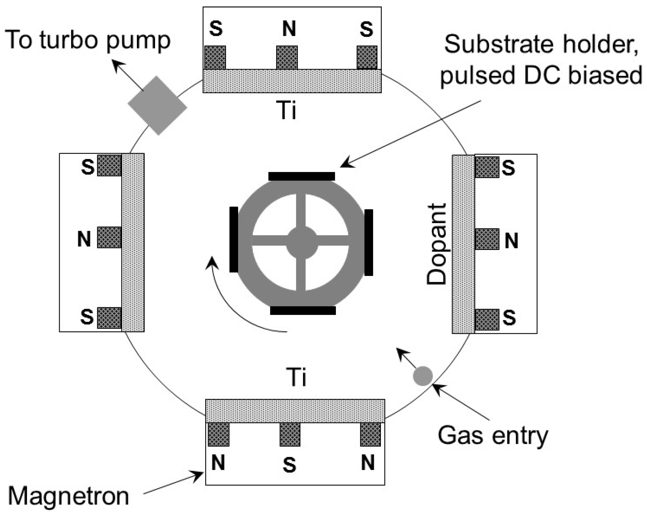
2.1. Preparation of Coated Surfaces

TiO2 and doped TiO2 coatings were deposited using reactive magnetron sputtering in a Teer Coatings UDP 450 coating system (Teer Coatings, Droitwich, UK). A schematic representation of the coating system is shown in Figure 1. Two titanium targets (99.5% purity) were used for the deposition of TiO2. Argon (99.998% purity) was used as the working gas and oxygen (99.5% purity) as the reactive gas. Ag, Cu and grade 316 stainless steel targets were used as dopants, the latter obviously providing mixed metallic dopants, primarily Fe, Cr and Ni, with other minor constituents, but still maintaining a high sputtering rate as a non-ferromagnetic material. Advanced Energy Pinnacle Plus pulsed DC power supplies were used to power the substrate and the titanium magnetrons and an Advanced Energy DC power supply was applied to the dopant material’s target. The substrate materials were grade 304 stainless steel plaques with a 2B finish (20 mm × 10 mm). All substrates were ultrasonically cleaned in acetone prior to loading in the deposition chamber to remove surface contaminants. The substrates were aligned on a flat plate parallel to the surface of the metal targets at a distance of 150 mm from the target plane and rotated at a speed of 10 rpm.
The substrates were ion-cleaned for a period of 20 min prior to the coating deposition using a pulsed-DC bias voltage of −400 V (77.5% duty cycle) and a low current of 0.2–0.35 A on the targets. The coatings were deposited at a pulsed-DC bias voltage of −40 V. The partial pressure of oxygen was controlled using an optical emission monitor and was set to 25% of the pure metallic emission line’s original intensity to obtain stoichiometric TiO2. The deposition time was 60 min for all coatings. Table 1 shows the magnetron target currents used for the deposition of coatings.

2.2. Heat Treatment

Heat treatment was carried out in air at 600 °C in a Prometheus Kiln for 30 min after which the coated samples were taken out of the kiln and allowed to cool to room temperature.

2.3. Coating Characterisation

Coating thickness was assessed using the ball crater taper section method (ASTM standard E1182-93 [27] and [28]) on coated substrates. Three measurements were taken for each sample and the average values are reported. Adhesion of the as-deposited and annealed coatings was evaluated using a Teer Coatings ST3001 Scratch Tester (Teer Coatings, Droitwich, UK) [29]. A 200 μm radius conical diamond indenter was used and the coated samples underwent a progressive load of 10–40 N at a rate of 10 N min−1 and velocity of 10 mm min−1. The scratch tracks were investigated using SEM in order to detect any flaking.
SEM (Cambridge Stereoscan 200, Cambridge Instruments Ltd., Cambridge, UK) was used to investigate the morphology of the coatings. An acceleration voltage of 15 kV was utilised. The compositional analysis of the doped coatings was performed using EDX at a minimum of five locations and was reported as the mean ±2σ.
Hardness measurements were performed on films deposited onto stainless steel substrate using a Fischerscope™ HM2000 micro-indentation system (Helmut Fischer GmbH, Sindelfingen, Germany). Tests were carried out with a Vickers diamond indenter with loads from 0.4 to 10 mN. During the penetration of the test surface by the indenter under load, hardness can be determined from the resultant load vs indentation depth curve (loading/unloading) which gives the value of composite hardness (comprising effects from both the coating and the substrate). The hardness reported here is the plastic hardness, HUplast, which is based on the lasting indentation after unloading. At least five indentation cycles were performed to create a mean value graph from which the value of hardness was calculated.
Advancing drop contact angle measurements with water were carried out at room temperature using a contact angle measuring instrument. At least six measurements were taken for each surface and the reported values are mean ±2σ.
X-ray diffraction (XRD) (Bruker D8 Advance X-ray Diffractometer, Bruker AXS, Karlsruhe, Germany) was used to evaluate the crystal structure of the coatings. XRD measurements were performed using a Cu Kα radiation (λ = 0.154 nm) in 2θ steps of 0.014°, and a low scan speed of 0.01°·s−1.

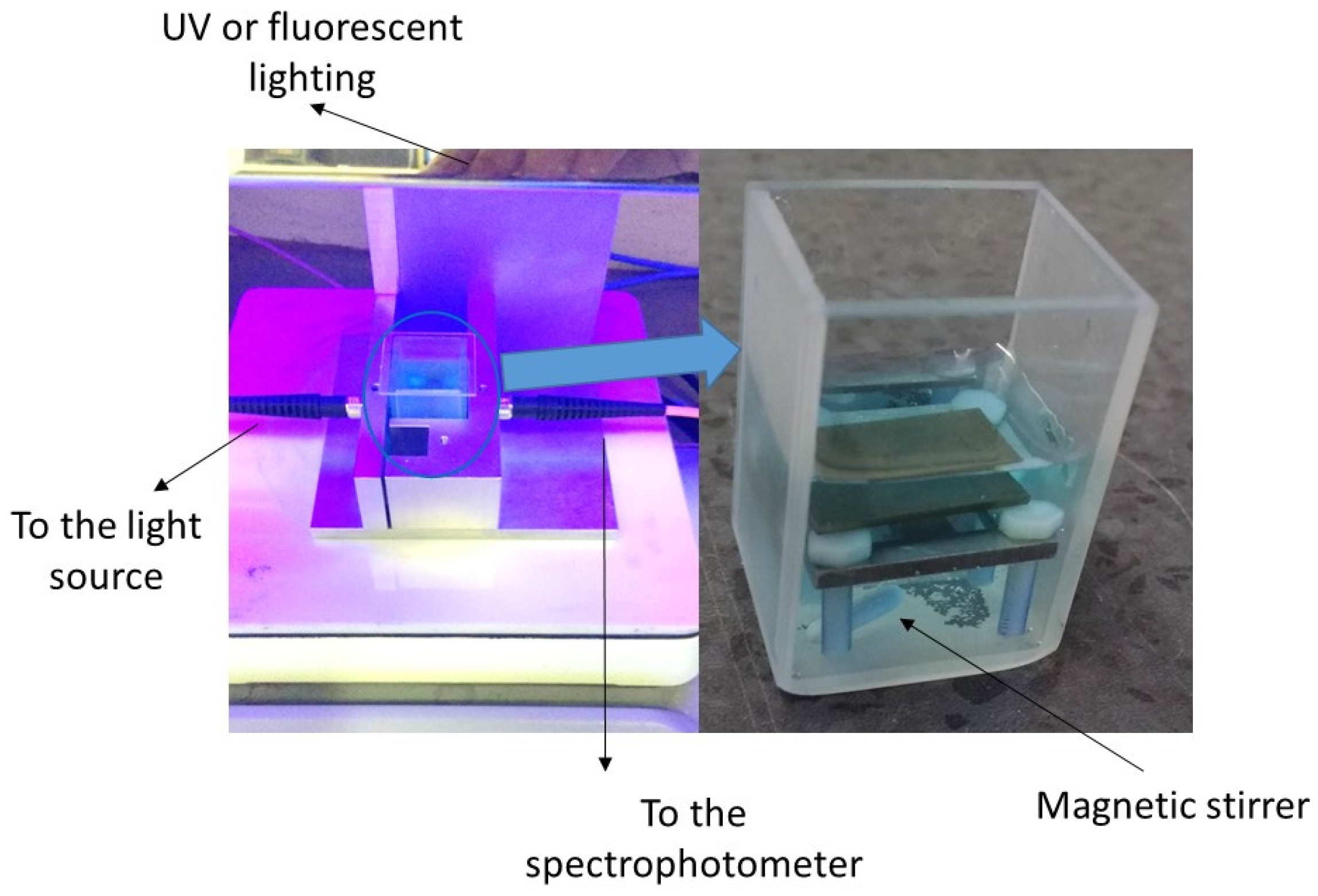
2.4. Photocatalytic Properties

The photocatalytic activities of the coatings were analysed using the methylene blue (MB) degradation assay under UV and fluorescent light sources [30]. In brief, MB solutions were made up to an initial concentration of 0.0105 mMol L−1. Photocatalytic surfaces were placed in 10 mL of the MB solution stirred using a magnetic stirrer at a rate of 120 rpm and irradiated at an integrated power flux of 40 W/m2 with two 15 W UV lamps (365 nm wavelength). Tests were also carried out using two 15 W fluorescent tubes in place of the UV tubes to simulate typical lighting environments. The integrated power flux to the coatings with the fluorescent tubes was 64 W/m2, of which the UV component (300–400 nm) was 13 W/m2. A 10 cm distance between the light source and MB solution was used. Absorption spectra were taken from the solution at 10 min intervals using an HR2000+ Ocean Optics spectrophotometer and the absorption peak at 650–668 nm was monitored over a period of 2 h. Figure 2 shows the setup used for the evaluation of methylene blue degradation using the coated surfaces.
According to the Lambert-Beer law, the concentration of dye is proportional to the absorbance value:
A = εcl
where A is absorbance, ε is the molar absorbance coefficient; l is the optical length of the cell where the photocatalyst is immersed into MB.
The photocatalytic decomposition of MB was approximated to first-order kinetics, as shown in the equation:
ln(C0/C) = kat
where C0 and C are the concentrations of MB solution at time 0 and time t of the experiment, respectively.
Since the absorbance decay is proportional to the concentration decay, the first-order rate constant, ka can be found from the slope of the plot ln(A0/A) against time. The rate constant should be normalised to take into account both the volume of the MB solution and the surface area of the substrate. The surface normalised rate constant, k” was calculated by multiplying ka with the reactor volume to catalyst area ratio [31].

3. Results and Discussion

Silver, copper and iron (as the main constituents of 316 steel) were selected as dopants for TiO2 and were co-deposited with titanium at two levels. As iron is ferromagnetic and hence difficult to sputter using magnetron sputtering and because one of the primary aims of this study was to deposit industrially scalable and economical coatings, a stainless steel target was used as the source of iron. Deposition times were adjusted to obtain coatings with a thickness of around 2 μm. The relative concentrations of titanium and dopant in the coatings were measured using EDX. It was not possible to measure the oxygen content in the coatings accurately using EDX. Table 2 shows the relative concentration of titanium and dopant in the coating, as well as its thickness and plastic hardness. Silver doping of TiO2 reduced its hardness whilst the addition of copper and low doping levels of stainless steel increased it.
SEM was used to analyse the surface topography (Figure 3) and XRD to analyse the microstructure (Figure 4) of the as-deposited coatings. All coatings were crystalline but the crystal structure and orientation were affected by the dopant type and content. Un-doped TiO2 showed several anatase peaks with (101) having the highest intensity. The addition of silver reduced the intensity of the (101) peak as well as the (004), (105) and (211) peaks but the coatings remained in anatase.
The addition of a small amount of copper did not change the structure of TiO2 significantly but further Cu resulted in the (101) peak disappearing and the occurrence of a strong peak at 38°, which could be a result of the TiO2 (112) orientation or also the appearance of the CuO (111) orientation. Coating with low concentrations of stainless steel dopants had a mixed anatase (112) and rutile (110) structure. The addition of higher concentrations of dopant resulted in the disappearance of the rutile peak and changed the crystal structure to anatase with (101) and (112) orientation. The magnified (101) anatase peak for TiO2 and doped TiO2 coatings is shown in Figure 5. A small broadening and shifting of this peak is seen in the doped coatings, indicating the distortion of the crystal lattice by these dopants.
Heat treatment of TiO2 has been reported to increase its crystallinity and photocatalytic performance [25,32]. The coatings in this work were therefore annealed at 600 °C in air to investigate the effect on the structure and properties. However, an evaluation of the surface topography revealed that heat treatment resulted in the segregation of significant amounts of the co-sputtered material from the TiO2 matrix (Figure 6), especially in the coatings with the higher dopant concentrations, suggesting that at least part of the material was not incorporated as a dopant for TiO2, but rather a separate phase.
Scratch testing of the coatings revealed that the as-deposited coatings had excellent adhesion to the substrate and no flaking was seen in the coatings with applied loads of up to 40 N. Annealing at high temperature, however, resulted in stressed coatings which had poor adhesion to the substrate. Figure 7 shows the scratch tracks of Ti and Ti-Cu1 before and after annealing.
Due to the fact that the as-deposited coatings were crystalline and had good mechanical properties, and due to the deterioration of the physical and mechanical properties after heat treatment, it was clear that there was no advantage in heat-treating these coatings and therefore further evaluation was limited to the as-deposited coatings.
Table 3 presents the water contact angle on the as-deposited coatings after being stored for a minimum of four weeks in the dark. The addition of silver and copper resulted in an increase in the water contact angle whilst the addition of stainless steel resulted in a decrease in the contact angle. After 30 min of irradiation with UV light, all coatings became superhydrophilic with a water contact angle of <10°.
The photocatalytic efficiency of the surfaces was evaluated from the decay in the absorbance peak using the slope of line ln(A0/A) vs. time. Table 4 presents the rate constant, ka, and the surface-normalised rate constant, k” [31].
Rafieian et al. [31] collated k” values for MB degradation in the presence of TiO2 prepared using various sputtering methods. The reported k” values range between 7.99 × 10⁻⁸ and 2.87 × 10⁻⁶ m s−1. The authors have also demonstrated the use of a microfluidic reactor for the evaluation of the rate constant which allowed them to extract the intrinsic rate constant without limitations due to inefficient mass transport and light distribution. The k” value obtained in their work was 5 × 10⁻⁵ m s−1. As in many of the applications of photocatalytic coatings, it was not possible to eliminate the mass transport and light distribution limitations; the use of reactors, such as that used in ISO Standard 10678:2010 [33] or that used in this work, is appropriate for the comparison of different coatings, especially as we tried to counter some of the effects of mass transport limitations through stirring the MB solution. The k” value for the TiO2 coating in this work under UV illumination was 1.5 × 10⁻⁶ m s−1 which was broadly in line with other sputtered TiO2 coatings and was hence used as a control to investigate the effectiveness of the different dopants.
Ti-Cu1 had the highest activity under both UV and fluorescent lights, with Ti-St2 matching its activity under fluorescent light. Other studies in the literature have also found the potential of copper in enhancing the photocatalytic activity of TiO2 [20,21]. The crystal structure of Ti-Cu1 was similar to that of Ti with the exception of a shift in the position of the anatase peak due to the distortion of the crystal lattice by Cu. It is possible that Cu has a role in preventing the recombination of photo-excited electrons and holes. Further work, however, is needed to establish the exact mechanism by which doping improves the photocatalytic activity of TiO2.
Most coatings were less active under fluorescent irradiation with the exception of Ti-Cu2 and Ti-St2, although Cu doping, even at a low concentration, enhanced the activity of TiO2 under fluorescent lighting.
Our previous work [24,26] showed the potential of magnetron sputtering for the deposition of photoactive TiO2 at high deposition rates and with excellent mechanical properties without a need for subsequent heat treatment. It also presented the potential of silver in improving the photocatalytic properties and imparting antimicrobial properties. The current work shows that co-sputtering a small amount of Cu during the reactive sputtering of TiO2 can enhance its UV activity by about 150% and its activity under fluorescent lighting by 32%. Furthermore, as in the case of Ag, Cu has antimicrobial properties [34] and could be expected to further contribute to the hygiene and self-cleaning properties of the coating, even under dark conditions.

4. Conclusions

The TiO2 coating was deposited using reactive CFUBMS at high deposition rates. Its structure and photocatalytic activity were compared with doped TiO2 coatings deposited by co-sputtering from a silver, copper or stainless steel (AISI 316) target. Two levels of dopant content were evaluated for each dopant material. All coatings were photocatalytic and showed superhydrophilicity after irradiation. The coating with low concentrations of Cu doping showed the highest photocatalytic activity compared with unmodified TiO2.

Acknowledgments

The authors acknowledge the support from InnovateUK (formerly Technology Strategy Board) for the MATERA+ Project “Disconnecting”, ref MFM-1855, Project No. 620015 for parts of this work.

Author Contributions

Parnia Navabpour and Kevin Cooke conceived and designed the experiments; Parnia Navabpour performed the experiments and analysed the data; all authors contributed to the writing of the manuscript.

Conflicts of Interest

The authors declare no conflict of interest.

References

  1. Dunnill, C.W.; Parkin, I.P. Nitrogen-doped TiO2 thin films: Photocatalytic applications for healthcare environments. Dalton Trans. 2011, 40, 1635–1640. [Google Scholar] [CrossRef] [PubMed]
  2. Miao, L.; Tanemura, S.; Kondo, Y.; Iwata, M.; Toh, S.; Kaneko, K. Microstructure and bactericidal ability of photocatalytic TiO2 thin films prepared by rf helicon magnetron sputtering. Appl. Surf. Sci. 2004, 238, 125–131. [Google Scholar] [CrossRef]
  3. Tanemura, S.; Miao, L.; Wunderlich, W.; Tanemura, M.; Mori, Y.; Toh, S.; Kaneko, K. Fabrication and characterization of anatase/rutile–TiO2 thin films by magnetron sputtering: A review. Sci. Technol. Adv. Mater. 2005, 6, 11–17. [Google Scholar] [CrossRef]
  4. Jiang, D.; Zhang, S.; Zhao, H. Photocatalytic degradation characteristics of different organic compounds at TiO2 nanoporous film electrodes with mixed anatase/rutile phases. Environ. Sci. Technol. 2007, 41, 303–308. [Google Scholar] [CrossRef] [PubMed]
  5. Andersson, M.; Österlund, L.; Ljungström, S.; Palmqvist, A. Preparation of nanosize anatase and rutile TiO2 by hydrothermal treatment of microemulsions and their activity for photocatalytic wet oxidation of phenol. J. Phys. Chem. B 2002, 106, 10674–10679. [Google Scholar] [CrossRef]
  6. Yin, H.; Wada, Y.; Kitamura, T.; Kambe, S.; Murasawa, S.; Mori, H.; Sakata, T.; Yanagida, S. Hydrothermal synthesis of nanosized anatase and rutile TiO2 using amorphous phase TiO2. J. Mater. Chem. 2001, 11, 1694–1703. [Google Scholar] [CrossRef]
  7. Fakhouri, H.; Pulpytel, J.; Smith, W.; Zolfaghari, A.; Mortaheb, H.R.; Meshkini, F.; Jafari, R.; Sutter, E.; Arefi-Khonsari, F. Control of the visible and UV light water splitting and photocatalysis of nitrogen doped TiO2 thin films deposited by reactive magnetron sputtering. Appl. Catal. B: Environ. 2014, 144, 12–21. [Google Scholar] [CrossRef]
  8. Wang, C.; Hu, Q.; Huang, J.; Wu, L.; Deng, Z.; Liu, Z.; Liu, Y.; Cao, Y. Efficient hydrogen production by photocatalytic water splitting using N-doped TiO2 film. Appl. Surf. Sci. 2013, 283, 188–192. [Google Scholar] [CrossRef]
  9. Wang, C.; Hu, Q.; Huang, J.; Deng, Z.; Shi, H.; Wu, L.; Liu, Z.; Cao, Y. Effective water splitting using N-doped TiO2 films: Role of preferred orientation on hydrogen production. Int. J. Hydrogen Energ. 2014, 39, 1967–1971. [Google Scholar] [CrossRef]
  10. Černigoj, U.; Štangar, U.L.; Trebše, P.; Ribič, P.R. Comparison of different characteristics of TiO2 films and their photocatalytic properties. Acta Chim. Slov. 2006, 53, 29–35. [Google Scholar]
  11. Rampaul, A.; Parkin, I.P.; O’Neill, A.O.; DeSouza, J.; Mills, A.; Elliott, N. Titania and tungsten doped titania thin films on glass; active photocatalysts. Polyhedron 2003, 22, 35–44. [Google Scholar] [CrossRef]
  12. Abdollahi Nejad, B.; Sanjabi, S.; Ahmadi, V. Sputter deposition of high transparent TiO2−xNx/TiO2/ZnO layers on glass for development of photocatalytic self-cleaning application. Appl. Surf. Sci. 2011, 257, 10434–10442. [Google Scholar]
  13. Samal, S.S.; Jeyaraman, P.; Vishwakarma, V. Sonochemical coating of Ag-TiO2 nanoparticles on textile fabrics for stain repellency and self-cleaning-the Indian scenario: A review. J. Mineral. Mater. Char. Eng. 2010, 9, 519–525. [Google Scholar]
  14. Chawengkijwanich, C.; Hayata, Y. Development of TiO2 powder-coated food packaging film and its ability to inactivate Escherichia coli in vitro and in actual tests. Int. J. Food Microbiolog. 2008, 123, 288–292. [Google Scholar] [CrossRef] [PubMed]
  15. Cushnie, T.P.T.; Robertson, P.K.J.; Officer, S.; Pollard, P.M.; Prabhu, R.; McCullagh, C.; Robertson, J.M.C. Photobactericidal effects of TiO2 thin films at low temperatures—A preliminary study. J. Photoelec. Photobiolog. A 2010, 216, 290–294. [Google Scholar] [CrossRef]
  16. Maneerat, C.; Hayata, Y. Antifungal activity of TiO2 photocatalysis against Penicillium expansum in vitro and in fruit tests. Int. J. Food. Microbiolog. 2006, 107, 99–103. [Google Scholar] [CrossRef] [PubMed]
  17. Daghrir, R.; Drogui, P.; Robert, D. Modified TiO2 for environmental photocatalytic applications: A review. Ind. Eng. Chem. Res. 2013, 52, 3581–3599. [Google Scholar] [CrossRef]
  18. Zaleska, A. Doped-TiO2: A review. Recent Pat. Eng. 2008, 2, 157–164. [Google Scholar] [CrossRef]
  19. Cao, Y.; Tan, H.; Tang, T.; Li, J. Preparation of Ag-doped TiO2 nanoparticles for photocatalytic degradation of acetamiprid in water. J. Chem. Technol. Biotechnol. 2008, 83, 546–552. [Google Scholar] [CrossRef]
  20. Colon, G.; Maicu, M.; Hidalgo, M.C.; Navıo, J.A. Cu-doped TiO2 systems with improved photocatalytic activity. Appl. Catal. B Environ. 2006, 67, 41–51. [Google Scholar] [CrossRef]
  21. Park, H.S.; Kim, D.H.; Kim, S.J.; Lee, K.S. The photocatalytic activity of 2.5 wt% Cu-doped TiO2 nano powders synthesised by mechanical alloying. J. Alloys Compd. 2006, 415, 51–55. [Google Scholar] [CrossRef]
  22. Andriamiadamanana, C.; Laberty-Robert, C.; Sougrati, M.T.; Casale, S.; Davoisne, C.; Patra, S.; Sauvage, F. Room-temperature synthesis of iron-doped anatase TiO2 for lithium-ion batteries and photocatalysis. Inorg. Chem. 2014, 53, 10129–10139. [Google Scholar] [CrossRef] [PubMed]
  23. Takeda, S.; Suzuki, S.; Odaka, H.; Hosono, H. Photocatalytic TiO2 thin film deposited onto glass by DC magnetron sputtering. Thin Solid Films 2001, 392, 338–344. [Google Scholar] [CrossRef]
  24. Navabpour, P.; Ostovarpour, S.; Tattershall, C.; Cooke, K.; Kelly, P.; Verran, J.; Whitehead, K.; Hill, C.; Raulio, M.; Priha, O. Photocatalytic TiO2 and Doped TiO2 Coatings to Improve the Hygiene of Surfaces Used in Food and Beverage Processing—A Study of the Physical and Chemical Resistance of the Coatings. Coatings 2014, 4, 433–449. [Google Scholar] [CrossRef]
  25. Ratova, M.; West, G.T.; Kelly, P. Optimisation of HiPIMS photocatalytic titania coatings for low temperature deposition. Surf. Coat. Technol. 2014, 250, 7–13. [Google Scholar] [CrossRef]
  26. Navabpour, P.; Ostovarpour, S.; Hampshire, J.; Verran, J.; Cooke, K. The effect of process parameters on the structure, photocatalytic and self-cleaning properties of TiO2 and Ag-TiO2 coatings deposited using reactive magnetron sputtering. Thin Solid Films 2014, 571, 75–83. [Google Scholar] [CrossRef]
  27. ASTM E1182-93(1998). Standard Test Method for Measurement of Surface Layer Thickness by Radial Sectioning; ASTM International: West Conshohocken, PA, USA, 1998.
  28. Walls, J.M.; Hall, D.D.; Sykes, D.E. Composition-depth profiling and interface analysis of surface coatings using ball cratering and the scanning auger microprobe. Surf. Interf. Anal. 1979, 1, 204–210. [Google Scholar] [CrossRef]
  29. Stallard, J.; Poulat, S.; Teer, D.G. The study of the adhesion of a TiN coating on steel and titanium alloy substrates using a multi-mode scratch tester. Tribol. Int. 2006, 39, 159–166. [Google Scholar] [CrossRef]
  30. Ratova, M.; West, G.T.; Kelly, P. Optimisation studies of photocatalytic tungsten-doped titania coatings deposited by reactive magnetron co-sputtering. Coatings 2013, 3, 194–207. [Google Scholar] [CrossRef]
  31. Rafieian, D.; Driessen, R.T.; Ogieglo, W.; Lammertink, R.G.H. Intrinsic photocatalytic assessment of reactively sputtered TiO2 films. ACS Appl. Mater. Interfaces 2015, 7, 8727–8732. [Google Scholar] [CrossRef] [PubMed]
  32. Eufinger, E.; Poelman, D.; Poelman, H.; De Gryse, R.; Martin, G.B. Effect of microstructure and crystallinity on the photocatalytic activity of TiO2 thin films deposited by dc magnetron sputtering. J. Phys. D Appl. Phys. 2007, 40, 5232. [Google Scholar] [CrossRef]
  33. ISO 10678:2010. Fine Ceramics (Advanced Ceramics, Advanced Technical Ceramics)—Determination of Photocatalytic Activity of Surfaces in an Aqueous Medium by Degradation of Methylene Blue; International Organisation for Standardization (ISO): Geneva, Switzerland, 2010.
  34. Wu, B.; Huang, R.; Sahu, M.; Feng, X.; Biswas, P.; Tang, Y.J. Bacterial responses to Cu-doped TiO2 nanoparticles. Sci. Total Environ. 2010, 408, 1755–1758. [Google Scholar] [CrossRef] [PubMed]
Figure 1. Schematic representation of the coating process.
Coatings 07 00010 g001
Figure 2. The experimental setup for the evaluation of MB degradation in the presence of coated surfaces.
Coatings 07 00010 g002
Figure 3. SEM images of the surface of coatings: (a) Ti; (b) Ti-Ag1; (c) Ti-Ag2; (d) Ti-Cu1; (e) Ti-Cu2; (f) Ti-St1; and (g) Ti-St2.
Coatings 07 00010 g003
Figure 4. XRD patterns of as-deposited TiO2 and doped TiO2 coatings.
Coatings 07 00010 g004
Figure 5. The position of (101) anatase peak in the XRD patterns of TiO2 and doped TiO2 coatings.
Coatings 07 00010 g005
Figure 6. SEM images of coated surfaces after heat treatment: (a) Ti-Ag1; (b) Ti-Ag2; (c) Ti-Cu1; (d) Ti-Cu2; (e) Ti-St1; and (f) Ti-St2.
Coatings 07 00010 g006
Figure 7. Scratch tracks on (a) as-deposited Ti, (b) heat-treated Ti, (c) as-deposited Ti-Cu1, and (d) heat-treated Ti-Cu1.
Coatings 07 00010 g007
Table 1. Target currents used for the deposition of coatings.
CoatingTi (A)Dopant (A)
Ti2 × 6
Ti-Ag12 × 60.5
Ti-Ag22 × 60.7
Ti-St12 × 60.5
Ti-St22 × 60.7
Ti-Cu12 ×60.5
Ti-Cu22 × 60.7
Table 2. Composition and mechanical properties of the coatings.
CoatingTi (at.%)Dopant (at.%)Thickness (μm)HU (GPa)
TiO2100.00.02.07.6 ± 0.1
Ti-Ag196.4 ± 1.03.6 ± 1.02.07.0 ± 1.1
Ti-Ag294.3 ± 1.85.7 ± 1.82.16.9 ± 0.6
Ti-Cu199.30.71.98.7 ± 0.3
Ti-Cu288.411.62.19.2 ± 0.5
Ti-St1N/A *N/A *2.310.3 ± 0.9
Ti-St2N/A *N/A *2.47.2 ± 0.4
* It was not possible to measure the concentration of the dopant in stainless steel–doped coatings as the EDX peak from the dopant could not be separated from that of the substrate.
Table 3. Water contact angles.
CoatingWater Contact Angle (°)
Ti55 ± 2
Ti-Ag166 ± 3
Ti-Ag279 ± 3
Ti-Cu156 ± 1
Ti-Cu281 ± 3
Ti-St136 ± 2
Ti-St241 ± 1
Table 4. Efficiency of coated surfaces under UV and fluorescent irradiation.
Coatingka (10−5 s−1)k (10−6 m s−1)
UltravioletFluorescentUltravioletFluorescent
Ti2.92.51.51.3
Ti-Ag13.62.21.81.1
Ti-Ag25.22.52.61.3
Ti-Cu17.23.33.61.7
Ti-Cu21.82.90.91.5
Ti-St12.22.01.11.0
Ti-St22.03.31.01.7

