Article

Durability Analysis and Experimental Validation of Environmental Barrier Coating (EBC) Performance Using Combined Digital Image Correlation and NDE

by
Ali Abdul-Aziz
1,* and
Adam C. Wroblewski
2
1
Department of Aerospace Engineering, College of Applied Engineering, Sustainability and Technology, Kent State University, Kent, OH 44242, USA
2
NASA Glenn Research Center, Cleveland, OH 44135, USA
*
Author to whom correspondence should be addressed.
Coatings 2016, 6(4), 70; https://doi.org/10.3390/coatings6040070
Submission received: 27 September 2016 / Revised: 2 December 2016 / Accepted: 7 December 2016 / Published: 16 December 2016

Abstract

:
To understand the failure mechanism or to predict the spallation life of environmental barrier coatings (EBC) on fiber reinforced ceramic matrix composites, the fracture strength of EBC and the process of the crack growth in EBC layers need to be experimentally determined under standard or simulated engine operating conditions. The current work considers a multi layered barium strontium aluminum silicate (BSAS)-based EBC-coated, melt infiltrated silicon carbide fiber reinforced silicon carbide matrix composite (MI SiC/SiC) specimen that was tensile tested at room temperature. Numerous tests were performed under tensile loading conditions, and the specimen was loaded until failure under pre-determined stress levels. The specimen was examined with optical microscopy, scanning electron microscopy (SEM), computed tomography (CT) scan, and digital image correlation (DIC) camera. Observation from the computed tomography scanning, the SEM, and the optical microscopy did not offer conclusive information concerning the cracks that spawned during the tests. However, inspection with the DIC camera offered some indication that cracks had developed and allowed their detection and the location of their initiation site. Thus, this study provides detailed discussion of the results obtained from the experimental investigation and the nondestructive evaluation (NDE), and it also includes assessment of the stress response predicted by analytical modeling and their impact on EBC durability and crack growth formation under complex loading settings.

1. Introduction

Ceramic matrix composite (CMC) materials such as (SiC/SiC) are becoming highly attractive to aero engine makers, making them prime candidates for use in turbine engines, particularly in the hot section part [1]. They hold unique characteristics and suitable properties, such as being light weight and can operate in high temperature environments—typically 200 °C higher than conventional superalloys. These are considered to be great advantages for the turbine engine manufacturer, since they will lead to much needed higher fuel efficiency and durability. Additionally, for these CMCs to perform in harsh environments—especially where high temperature and moisture are present—they have to be coated with a protective coating, such as silica. Under these conditions, the silica dissociates, causing recession of the substrate (the CMC) [2]. Such scenarios have led to the development of multilayered environmental barrier coatings (EBC) that can operate efficiently at high temperatures up to 1450 °C, while a newer set of advanced coatings are being developed for much higher temperature applications [3,4,5,6]. Generally, the EBC recesses during engine operating conditions, but at a lower rate than the CMCs. It further undergoes creep, sintering, and endures multiaxial stress and foreign objects damage. Under the latter conditions, the EBC experiences vertical cracking that is normal to the substrate and grows to the bond/intermediate coat interface or to the bond/substrate interface. Because of these actions, an oxidation process takes place and forms a growth of amorphous silica [7]. The amorphous silica changes state to become crystalline silica, leading to “T” crack formations and causing spallation of the EBC. Correspondingly, other issues that further contribute to the formation of these cracks arise from the mismatch of the thermal expansion coefficient (CTE) between the coatings and the surface layer, since under the operating conditions of a turbine engine, different CTEs lead to shrinkage and residual stresses that accumulate at the coating/substrate interface and eventually cause failure of the EBC [8,9]. Additionally, CTE mismatch and thermal cycling can induce tensile or compressive stresses, which may result in cracking or spallation of the EBC layers [10,11,12]. When the coating is compromised, subsequent exposure to the harsh engine environment severely reduces the lifetime of the component. Therefore, it is critical to minimize these stresses when possible. This indicates that materials with CTEs similar to those of the applicable substrate should be considered for the coatings [13].
While substantial activities and studies have been performed in CMCs and EBC recession/degradation mechanisms, there remains ample work to research the crack initiation in the coating, the crack propagation in the layers, and the connection between the cracks and the spallation phenomena [5,6]. Thus, the objectives of this study are to demonstrate the efficacy of applying optical techniques such as digital image correlation (DIC), computed tomography (CT), and microscopy, along with analytical modeling to monitor the crack propagation and assess damage in the EBC. Results showed that the CT and the optical microscopies did not offer much needed information about the crack propagation; however, the DIC was relatively practical in tracing the crack origination that led to the specimen failure.

2. Experimental Procedure

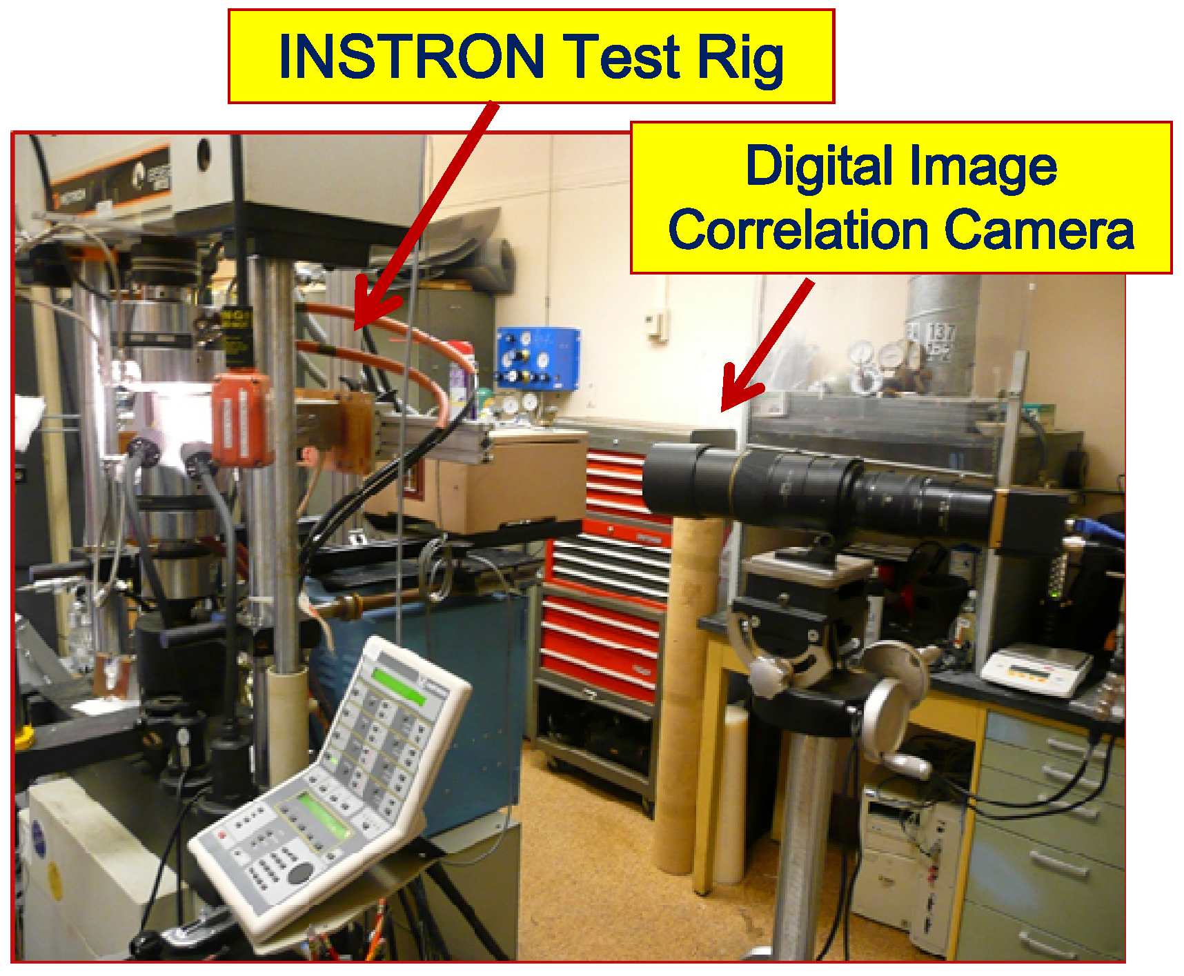
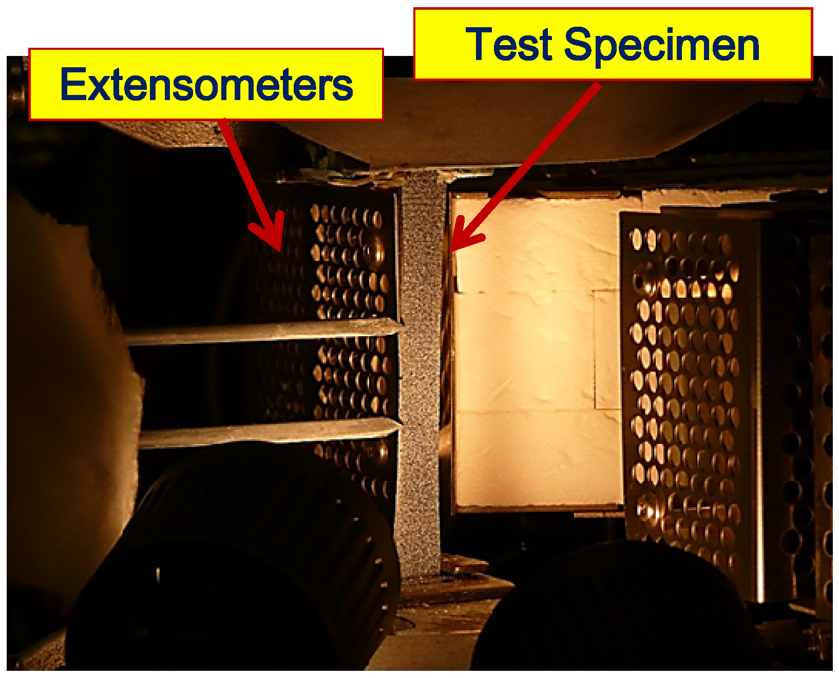
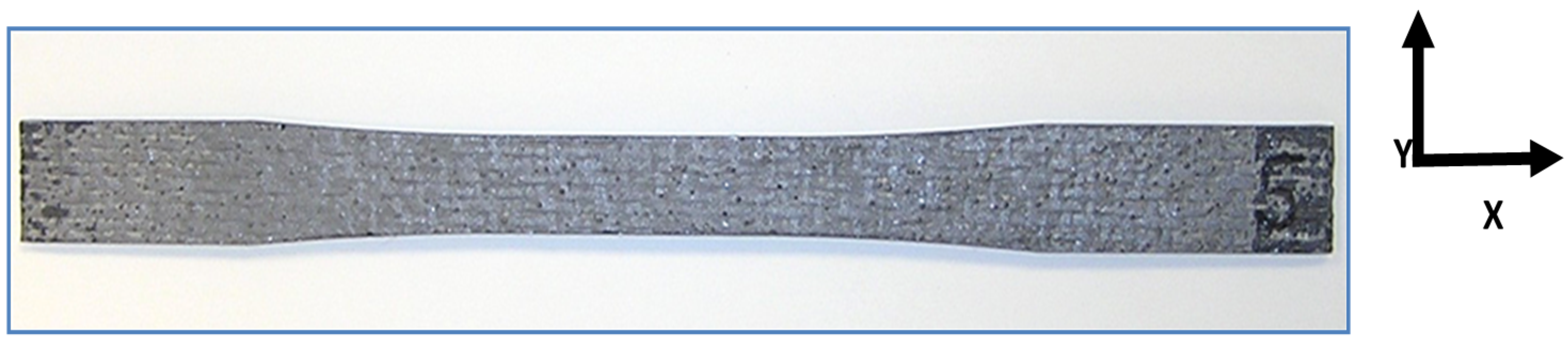
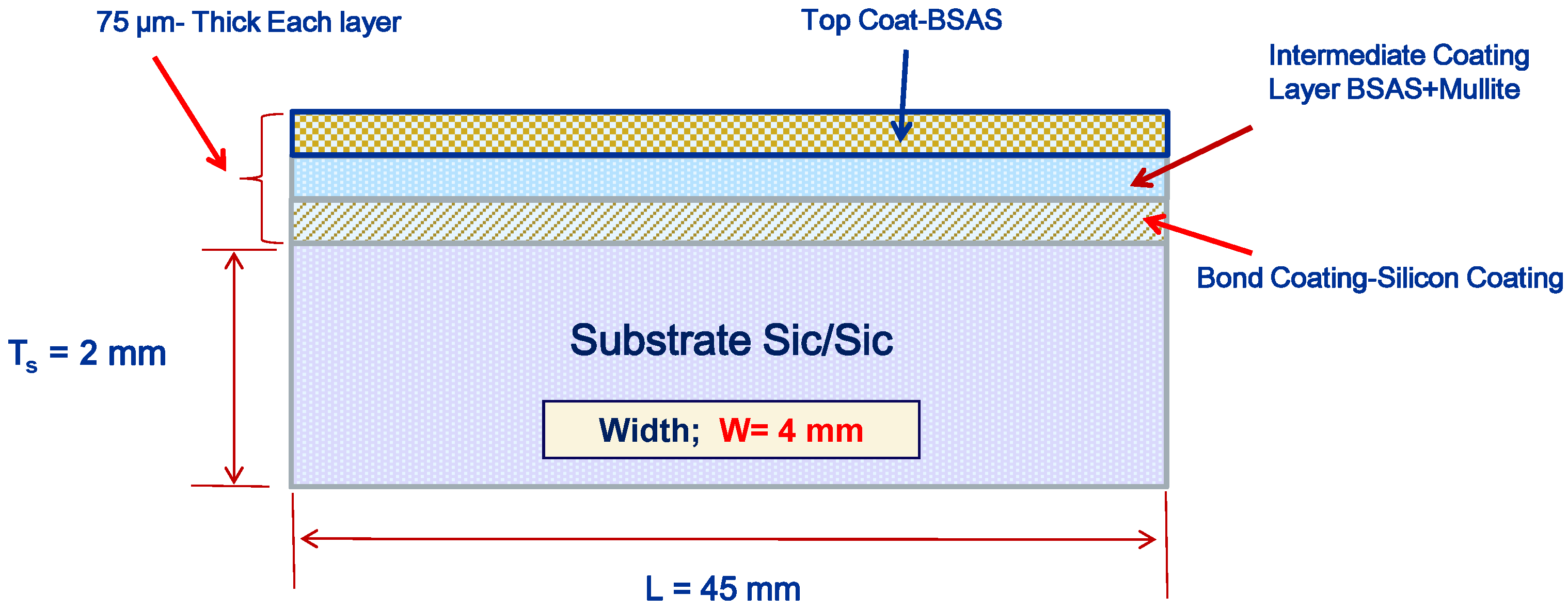
2.1. Experimental Setup and Specimen Description

Dog bone specimen shapes were used in the testing, and they were made from composite ceramic products such as crystalline oxide, nitride, or carbide material. The fabrication process of the composite included combing slurry casting and melt infiltration techniques [8]. The dimensions of the dog bone specimen were 152 mm (L), 13 mm (W), and 2.4 mm (T), with a reduced gauge section. The environmental barrier coating (EBC) layers were deposited on the specimens by atmospheric plasma spray (APS) method. The EBC coating consists of three sub-layers: first a bond coat layer of 75 μm-thick silicon was deposited on top of the substrate, followed by an intermediate mixed layer of 75 μm-thick mullite + barium strontium aluminum silicate (BSAS), and then by a top layer of 75 μm-thick BSAS [14].
The testing was carried out at the materials laboratory at NASA Glenn Research center using a servo-hydraulic test frame equipped with self-aligning grips. A spring-loaded extensometer was attached to the 25 mm-long straight section of the dog-boned specimen to monitor the displacement (see Figure 1 and Figure 2).
The displacement in the gauge region was monitored during the test with the DIC, and the loading rate was implemented by stepping up the load at a rate of 4 kN/min, followed by unloading. This was set such that the rate resulted in a load of 3000 N, being equivalent to a 50% of the material ultimate tensile stress (UTS) of the material. Upon unloading, the tested specimen was examined with optical microscope, SEM, and the CT for damage and crack detection purposes of the EBC. The progression of loading, unloading, and examination of the sample continued until ultimate fracture.

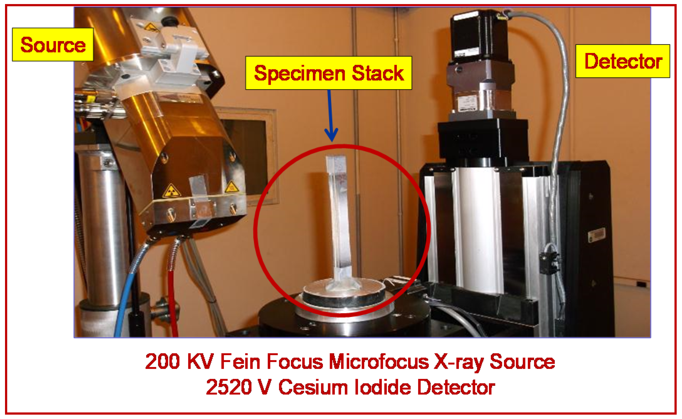
2.2. Nondestructive Evaluation (NDE) Equipment Facility

The NASA Glenn Rover is a cart-mounted portable computed tomography system equipped with a 200 kV Fein focus microfocus X-ray source [15]. This system includes a four-axis motion control unit with a 16” (40.64 cm) swing diameter, a Varian 2520 V Cesium iodide detector, a Windows dedicated workstation, and all acquisition, processing, and visualization software (Figure 3). The CT system can be combined with microfocus digital radiography. The resolution limit of the system is 10 µm (0.0005 in.). By changing the current X-ray source to a Nano head resolution, the limit can be improved to 5 µm at the expense of increased acquisition.

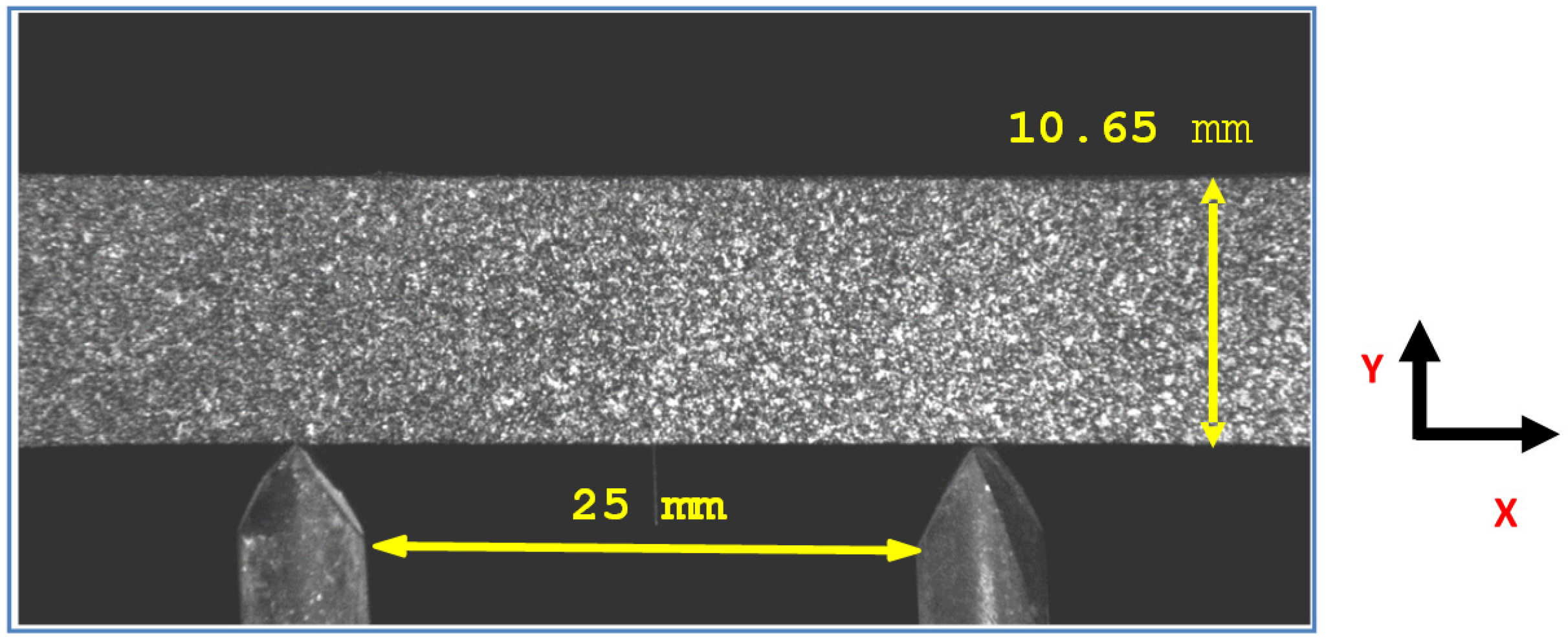
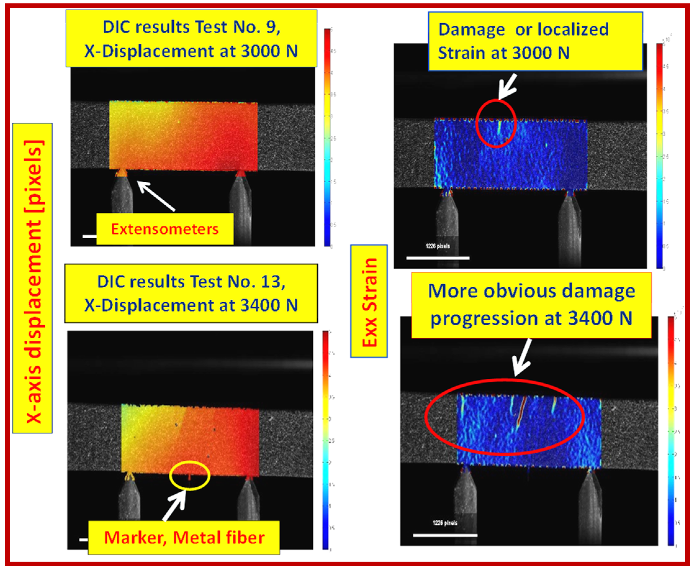
2.3. Digital Image Correlation

Digital Image Correlation is a 3D, full-field, non-contact optical technique to measure contour, deformation, vibration, and strain fields on most materials. The DIC is a simple system to use and is cost effective compared to other available techniques [16]. It can be used in various tests, including tensile, torsion, bending, and combined loading such as static and dynamics. It has become quite a practical and accurate non-contact measurement solution [17]. DIC compares digital photographs of a component or a test specimen at various stages of deformation. 2D or 3D displacement fields are generated upon applying image tracking and registration algorithms. This leads to computing the strain fields. For an accurate representation of the results, the pixel blocks need to be random and unique with a range of contrast and intensity levels.

DIC Test Configuration

The DIC system in this work captures 2D displacement and strain fields using an Imperx™ 16 MP monochrome camera coupled to a 300 mm lens, capturing images at a rate of 2.0 Hz. An extension tube and tele-converter are used to achieve the desired magnification, while placing the lens at an approximate distance of 1.5 m. This hardware configuration permitted high zoom with minimized perspective distortion. Imposing a perpendicular view as desired was not possible, due to the tensile rig configuration; therefore, an approximate angle of deviation of 3.5° was used. This permitted maintaining full focus across the entire specimen. The camera and the test rig set-up including the specimen are shown in Figure 1 and Figure 2.
Image acquisition was triggered manually at the same time that the tensile test was initiated. Loading of the specimen began consistently 10 s after the test had started. The image series were recorded for the entire test cycle in a fashion that accounted for the beginning and end images and allowed the gauge section displacement and strain to be easily computed. The CMC specimen was sprayed with both white and black paint to generate a binary speckle pattern to enable enhanced resolution exposure, see Figure 4. The field of view is approximately 5 cm (1.9685 in) long, which allowed a resolution of 10.76 µm/pixel on the object plane. The DIC image processing is based on a single reference image that represents the specimen in the unloaded state. Several evenly distributed images in time are then selected as the data images cross-correlate with the reference image. Through computation of normalized cross-correlation coefficients, the displacement field is generated, then Green–Lagrangian strains are computed [18].

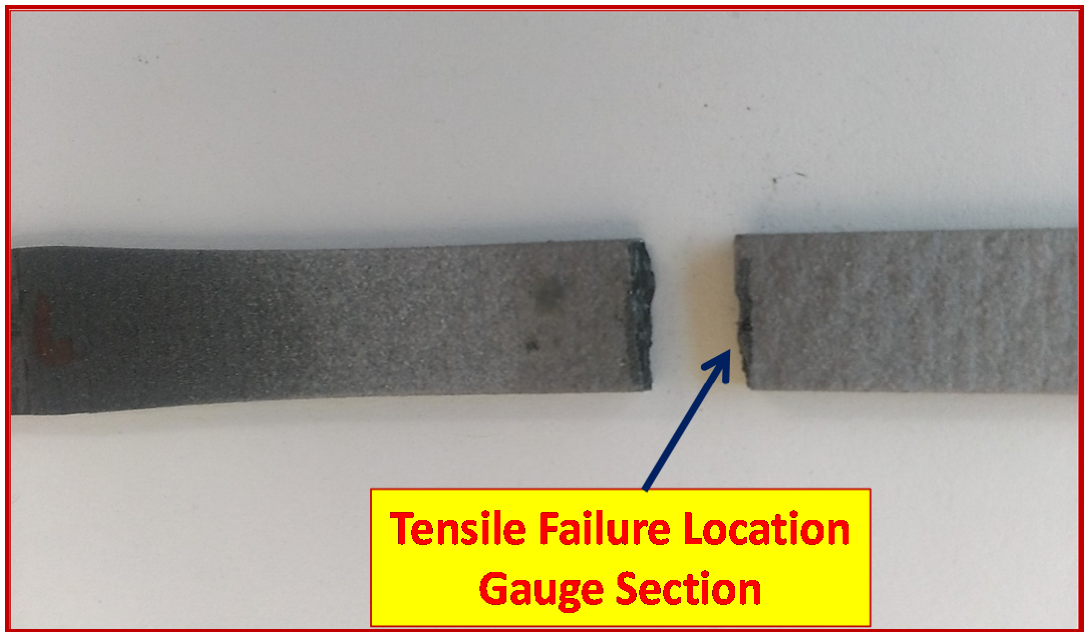
3. Results and Discussion

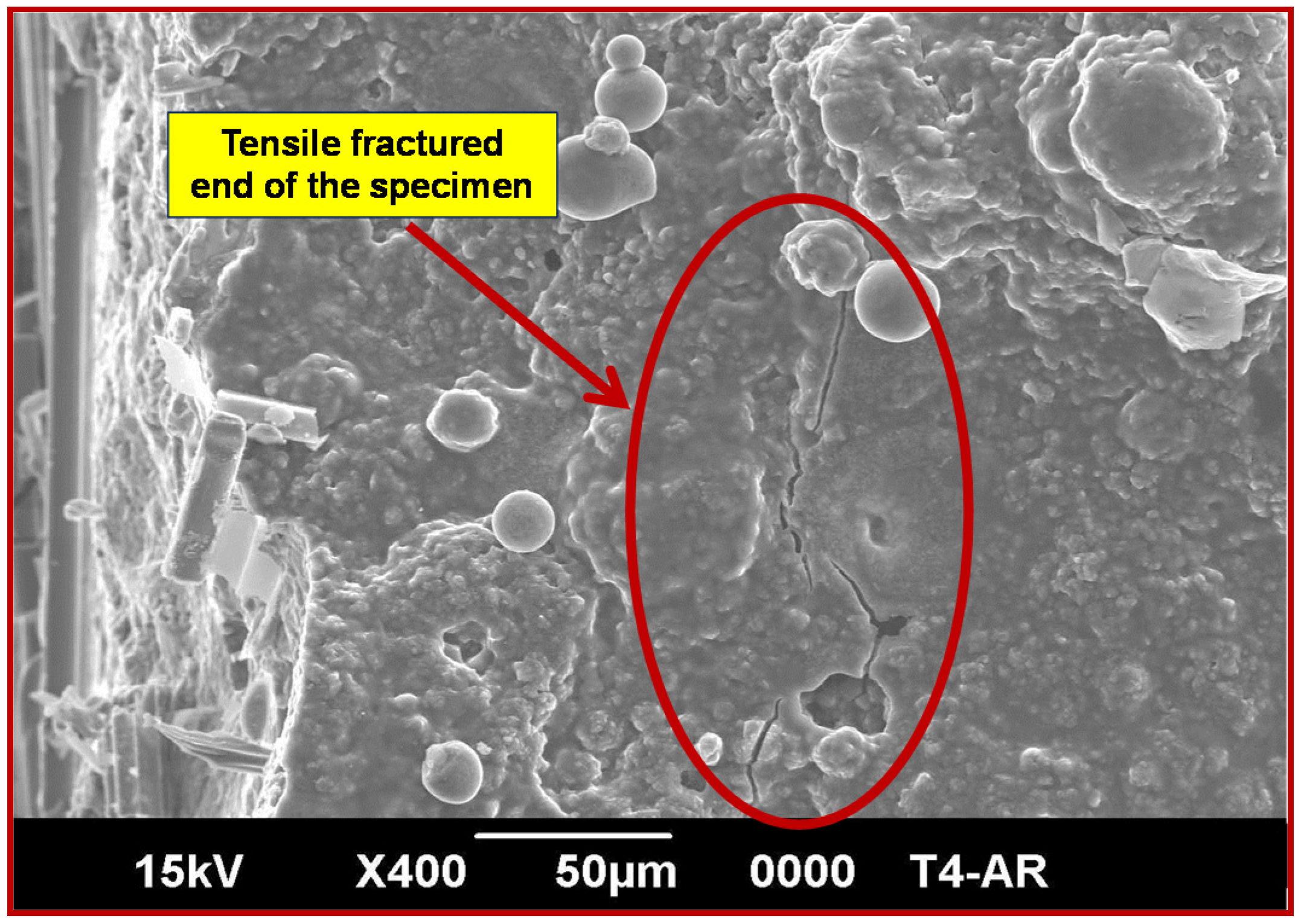
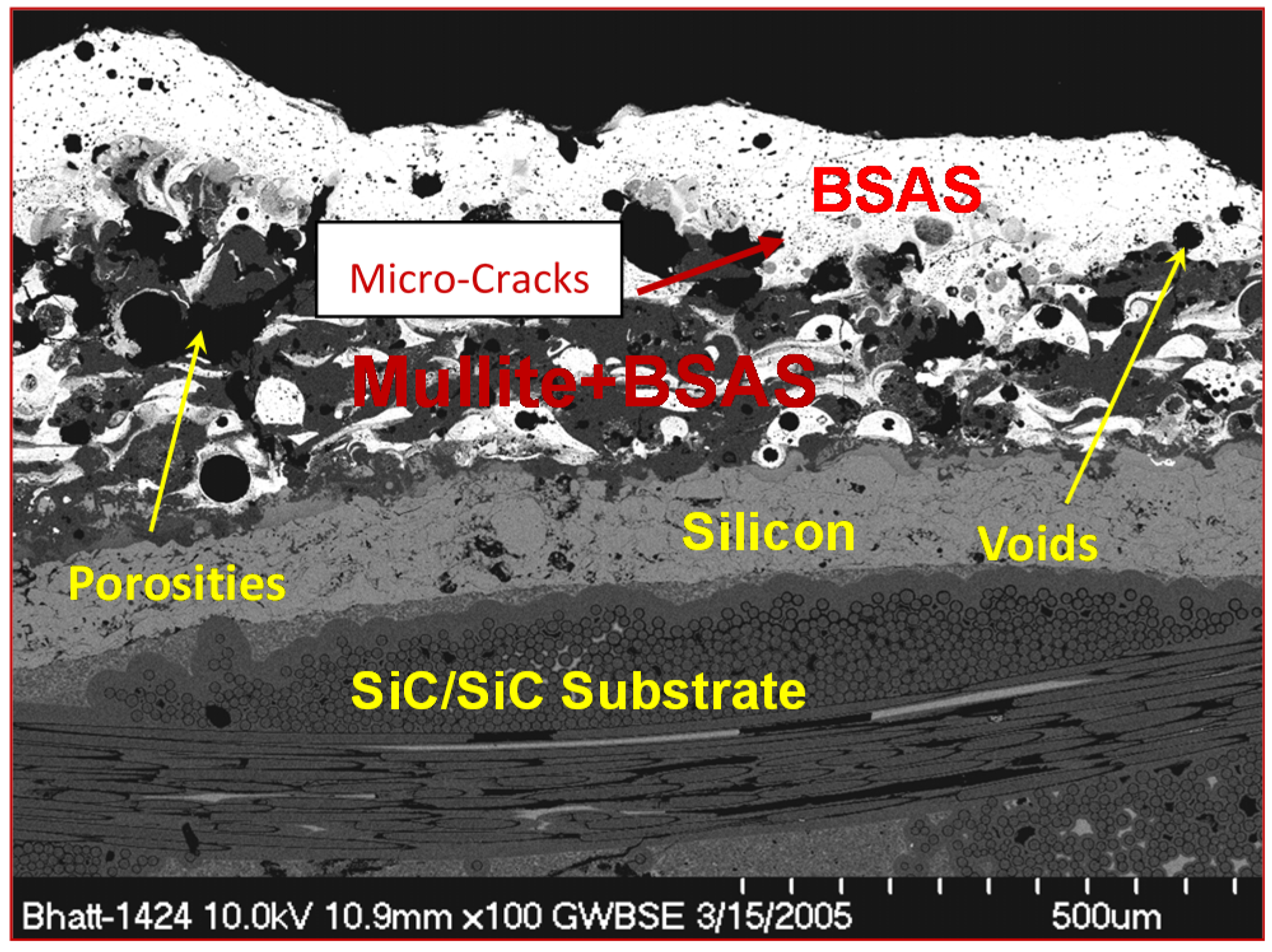
3.1. EBC Coated Dog-Bone Specimen and EBC Microstructure

Figure 5 shows an optical photograph of an EBC coated melt infiltrated silicon carbide fiber reinforced silicon carbide matrix (MI SiC/SiC) composite dog-bone specimen, and Figure 6 depicts a schematic cross-section showing details of the EBC sub-layer and substrate thicknesses.
An SEM photograph of the cross section of a typical air plasma sprayed tri-layered environmental barrier coating on a MI SiC/SiC composite substrate is shown in Figure 7. The sub-layers of the coating are inhomogeneous, and contain micro-cracks and significant levels of non-uniform pores.

3.2. NDE Results—Optical and CT Scan

After unloading from each interrupted tensile test, the gauge section of the specimen was observed under an optical microscope and further examined by conducting a follow up CT scan. Due to extreme surface roughness of the EBC, the optical microscope images of the EBC could not isolate the surface cracks. Neither technique—the optical microscopy or the CT—offered any valid evidence of EBC or CMC cracking until ultimate tensile failure of the specimen. The probable cause of this is that cracks that formed in the EBC coating during loading closed upon unloading. This action initiated a relief caused by the crack. Therefore, it was problematic to identify the cracks. Additional causes can be attributed to the surface roughness of the EBC coatings, the capabilities of the optical microscope, and the resolution of the CT scan and the high atomic contrast of the EBC coating in CT images. Figure 8 shows the specimen tensile failure at the gauge section.
A secondary crack was formed on the EBC coating when it was examined via scanning electron microscope (SEM). Figure 9 shows the details of the crack, which is located close to the fractured end of the specimen. The opening of this crack is approximately smaller than 1 µm.

3.3. DIC Observations

A validation test was performed to ensure that the DIC strain data coincides well with the extensometer results (see reference [7]). This was performed by averaging the 2 D strain data files at each time step in the area between the extensometer prongs, as shown in Figure 10. The results were filtered to exclude the noisy data near the edges. The comparison was well within the expected range. In this figure, the computed data sets are pictured as displacement in pixel units and strain. Note that a metal marker was attached to the specimen to serve as reference point to identify the center of the specimen.
Furthermore, Figure 10 shows variation of both the axial displacement profile and the axial strain due to the loading applied. The changes in the color fringes are obvious; for instance, a crack initiation can be traced at 3000 N, and as the load increases to the pre-failure load level of 3400 N (138 MPa specimen stress, which is equivalent to 75% of the UTS), the crack opens up and propagates further.
Variation of gauge section strain computed from DIC with increasing stress until specimen fracture is shown in Figure 11. It should be noted that this figure is confined to the gauge section. It is also apparent that the major crack has initiated in the top layer of EBC, and the crack grows with increasing stress. Moreover, it can be seen in Figure 11 that the primary crack that resulted in final failure matched with the location of crack initiation shown in Figure 10 at 3400 N load.
During the loading process beginning at 3000 N load, an indication of a high local strain (crack) appears in the top center of the strain field (Figure 10). At each increasingly larger load, the local strain in that crack region increases, as well as the introduction of several other localized strains. As anticipated, the final specimen failure occurs in the region where highest localized strain is evident.
This confirms that the DIC offered more information about the crack initiation compared with optical microscopy and CT. The specimen failed at 3700 N or a failure stress of 140 MPa. Please note that the red and blue colors shown in Figure 11 are tailored fringe plots generated by the custom software used to illustrate the results obtained from the DIC. They highlight the area of high strains where the crack is starting, and ultimately the location of the failure region. Additionally, this trend is fully explained in reference [7], including the relevant tensile stress–strain data generated from all the individual interrupted tests.

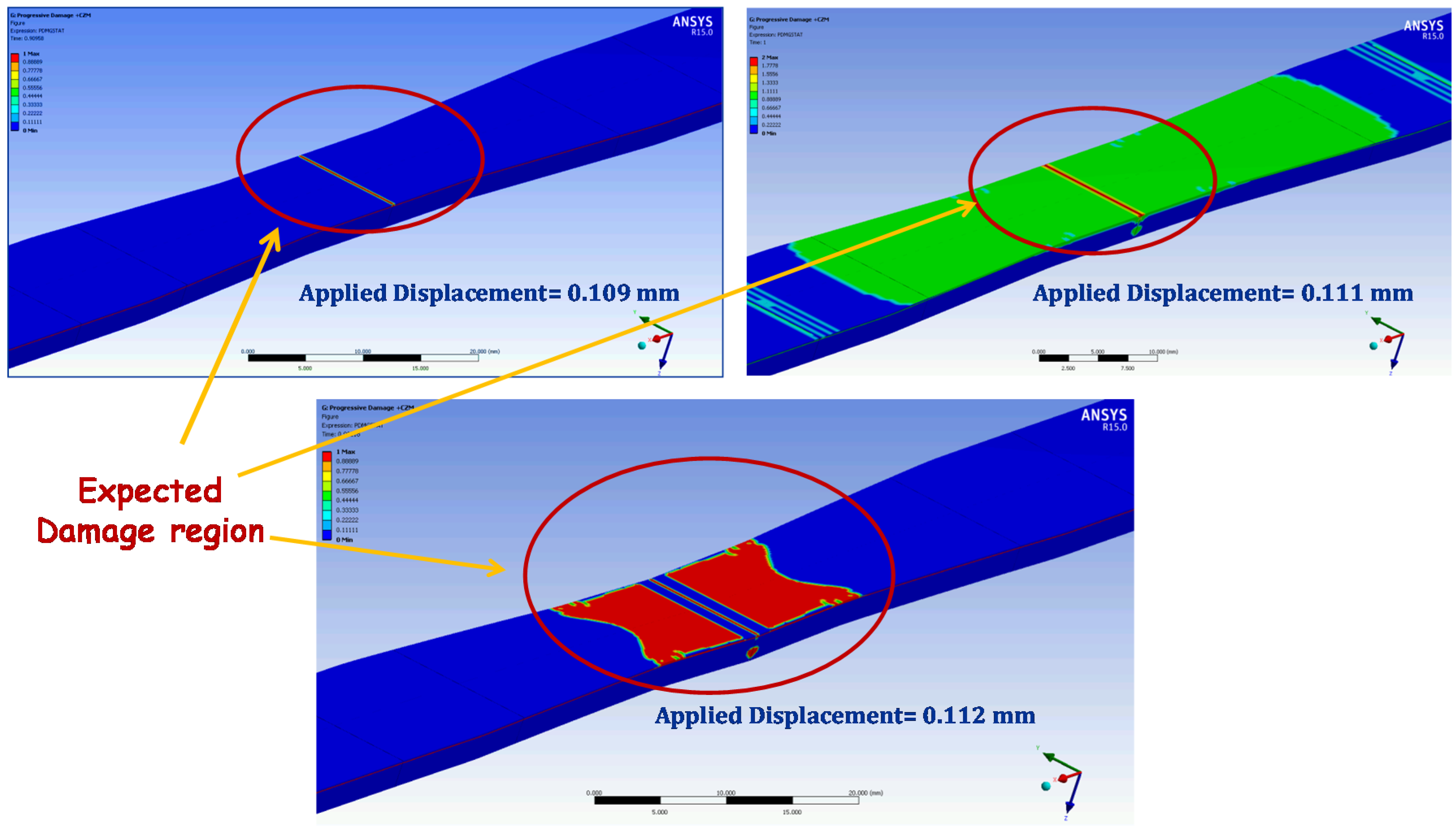
4. Durability Modeling

To confirm or validate the experimental activities and gain an assessment of the failure mechanism experienced by the test sample and in order to pinpoint the crack initiation site, a supportive analytical modeling under progressive failure analysis (PFA) was carried out [7]. The PFA is a finite element-based calculation approach, and it is performed to model the coated dog-bone specimen with three layers of EBC and a CMC substrate. The model is developed to estimate the stress response based on the known processing conditions of the coating, the specimen geometry, and the thermomechanical properties of the coated layers and the substrate. Thermo-mechanical properties, including thermal expansion coefficient, specific heat, thermal conductivity, stiffness, Poisson’s’ ratio, and strength for all four materials constituting the EBC/CMC specimen are used in the input model. The SiC/SiC CMC material lamina properties of the fabric are obtained from reference [19]. Multi-site micro-cracking and any type of plastic deformation that may occur in the plasma sprayed coating are not considered in the model.
The analysis covered an attempt to simulate the experimental conditions, and thus to identify the failure occurrence experienced by the EBC. The data obtained from the analysis clearly indicated that on the specimen, initiation and propagation starts once all coating layers experience damage. Figure 12 shows this damage initiation and propagation of the SiC/SiC layer. Due to the brittle nature of the CMC, the damage propagates rather quickly and spreads over the width of the specimen. This shows that the damage would start at the two locations in the specimen if (1) we have identical properties in all the materials data points, such as the modulus, Poisson’s ratio, thermal coefficient of expansion, and so on in the substrate; and (2) identical geometric dimensions in terms of material thickness. Furthermore, it would be worth noting that the failure and damage behavior is tied to the material and geometric variability. The results obtained further showed that the tensile stress–strain curve is essentially linear until failure. This is significantly different from what has been reported in the literature for uncoated MI SiC/SiC composites similar to the substrate material used in this study [17].
A typical tensile stress–strain curve of a MI SiC/SiC composite has typically bilinear behavior: a linear elastic region until matrix fracture, followed by a second linear region in which matrix progressively cracks until final fracture [20,21]. The analytical modeling concluded that the crack initiation is in good agreement with experimental results confirming the validity of the modeling approach applied. More in depth analyses concerning the failure behavior and the modes of durability can be found in reference [7].

5. Conclusions

A coated MI Sic/Sic composite dog-bone specimen was tested under tensile loading conditions at room temperature to determine the failure behavior and understand the crack initiation/propagation of the EBC. The testing involved the application of an incremental load to a certain fraction of the ultimate tensile stress and unloading it. An analytical validation using finite element method was carried out to validate the failure behavior and identify the crack initiation site. The following conclusions were drawn from this combined analytical and experimental exercise.
Optical microscopy was not very effective in capturing the surface cracks of the EBC due to the rough surface and the poor depth of focus of the optical microscope.
The CT scan was equally ineffective in identifying the cracks due to the resolution limitations.
The DIC offered very good representation in determining the crack initiation on the top EBC layer that led to the final fracture of the test sample. The presence of secondary cracks was seen on the strain plots at stresses close to UTS, but their presence was not established by SEM.
Compared to the other NDE techniques applied, the DIC performed better in determining the crack initiation; however, one limitation of its use is the high temperature capability, which is typically needed in monitoring deformation and cracking in composite materials.
Additional verification is needed to confirm that the DIC is an appropriate methodology for characterizing materials failure behavior.
The analytical validation supported the experimental findings by identifying the initiation of the damage evolution sequence that led to the specimen failure. This reinforced the confirmation of the accuracy of the analytical model being developed.
More testing and analytical confirmation are warranted to validate that the above findings will support the development of a physics-based fracture mechanics model to study the crack initiation of EBCs.

Acknowledgments

This work is the property of the US government and subject to the US Government copy rights law. No other funding was received.

Author Contributions

The primary author of this manuscript is Ali Abdul-Aziz and he is the one who wrote and prepared the article. Adam Wroblewski the co-author was the individual who performed the DIC measurements and the DIC data analyses. Abdul-Aziz performed all the analytical and other related supportive work.

Conflicts of Interest

The authors declare no conflict of interest.

References

  1. Jorgensen, P.J.; Wadsworth, M.E.; Cutler, I.B. Oxidation of silicon carbide. J. Am. Ceram. Soc. 1959, 42, 613–616. [Google Scholar] [CrossRef]
  2. Smialek, J.L.; Robinson, R.C.; Opila, E.J.; Fox, D.S.; Jacobson, N.S. SiC and Si3N4 recession due to SiO2 scale volatility under combustor conditions. Adv. Compos. Mater. 1999, 8, 33–45. [Google Scholar] [CrossRef]
  3. Lee, K.N.; Fox, D.S.; Robinson, R.C.; Bansal, N.P. Environmental Barrier Coatings for Silicon-Based Ceramics. In High Temperature Ceramic Matrix Composites; Krenkel, W., Naslain, R., Schneider, H., Eds.; Wiley-Vch: Weinheim, Germany, 2001. [Google Scholar]
  4. Lee, K.N.; Fox, D.S.; Bansal, N.P. Rare Earth Environmental Barrier Coatings for SiC/SiC Composites and Si3N4 Ceramics. J. Eur. Ceram. Soc. 2005, 25, 1705–1715. [Google Scholar] [CrossRef]
  5. Zhu, D.M.; Bansal, N.P.; Miller, R.A. Thermal conductivity and stability of HfO2-Y2O3 and La2Zr2O7 evaluated for 1650 °C. In Proceedings of the 105th Annual Meeting and Exposition of the American Ceramic Society, Nashville, TN, USA, 27–30 April 2003.
  6. Lee, K.N. Current status of environmental barrier coatings for Si-based ceramics. Surf. Coat. Technol. 2000, 133, 1–7. [Google Scholar] [CrossRef]
  7. Abdul-Aziz, A.; Adam, C.; Wroblewski, R.T.; Bhatt, M.H.; Jaskowiak, D.G.; Richard, W.R. Assessment of NDE methods for detecting cracks and damage in environmental barrier coated CMC tested under tension. In Proceedings of SPIE Smart Structures and Materials + Nondestructive Evaluation and Health Monitoring, San Diego, CA, USA, 8 March 2015.
  8. Harder, B.J.; Faber, K.T. Transformation kinetics in plasma-sprayed barium-and strontium-doped aluminosilicate (BSAS). Scr. Mater. 2010, 62, 282–285. [Google Scholar] [CrossRef]
  9. Aparicio, M.; Duran, A. Yttrium silicate coatings for oxidation protection of carbon–silicon carbide composites. J. Am. Ceram. Soc. 2000, 83, 135–1355. [Google Scholar] [CrossRef]
  10. Evans, A.G.; Hutchinson, J.W. On the mechanics of delamination and spalling in compressed films. Int. J. Solids Struct. 1984, 20, 455–466. [Google Scholar] [CrossRef]
  11. Lee, K.N. Key durability issues with mullite-based environmental barrier coatings for Si-based ceramics. J. Eng. Gas Turbine Power 2000, 122, 632–636. [Google Scholar] [CrossRef]
  12. Thouless, M.D. Cracking and delamination of coatings. J. Vac. Sci. Technol. 1991, 9, 2510–2515. [Google Scholar] [CrossRef]
  13. Kim, C.; Heo, Y.S.; Kim, T.W.; Lee, K.S. Fabrication and characterization of zirconia thermal barrier coatings by spray drying and atmospheric plasma spraying. J. Korean Ceram. Soc. 2013, 50, 326–332. [Google Scholar] [CrossRef]
  14. Feng, F.J.; Lee, D.H.; Park, J.Y.; Lee, K.S. Characterization of sintered silicates for environmental barrier coating materials. J. Ceram. Proc. Res. 2016, 17, 11–16. [Google Scholar]
  15. Lau, S.K.; Calandra, S.J.; Ohnsorg, R.W. Process for making silicon carbide reinforced silicon carbide composite. US 5840221 A, 2 December 1996. [Google Scholar]
  16. PerkinElmer Medical Imaging; Perkin Elmer, Inc.: Santa Clara, CA, USA.
  17. Baid, H.; Christoph, S.; Himadri, S.; Ajit, M. Dispersion of Lamb waves in a honeycomb composite sandwich panel. Ultrasonics 2015, 56, 409–416. [Google Scholar] [CrossRef] [PubMed]
  18. Roode, M.V.; Bhattacharya, A.M.; Ferber, M.K.; Abdi, F. Creep Resistance and water vapor degradation of SiC/SiC ceramic matrix composite gas turbine hot section components. In Proceedings of ASME Turbo Expo 2010: Power for Land, Sea, and Air, Glasgow, UK, 14–18 June 2010.
  19. Schreier, H.; Orteu, J.-J.; Sutton, M.A. Image Correlation for Shape, Motion and Deformation Measurements: Basic Concepts, Theory and Applications; Springer-Verlag: Boston, MA, USA, 2009. [Google Scholar]
  20. Morscher, G.N.; DiCarlo, J.A.; Kaiser, J.D.; Yum, H.M. Effects of Fiber Architecture on Matrix Cracking for Melt-Infiltrated SiC/SiC Composites. Int. J. Appl. Ceram. Technol. 2010, 7, 276–290. [Google Scholar] [CrossRef]
  21. McCormick, N.; Lord, J. Digital image correlation. Mater. Today 2010, 13, 52–54. [Google Scholar] [CrossRef]
Figure 1. Camera configuration and tensile rig.
Coatings 06 00070 g001
Figure 2. Specimen illuminated by halogen lamps.
Coatings 06 00070 g002
Figure 3. Photograph of the computed tomography facility at NASA Glenn.
Coatings 06 00070 g003
Figure 4. Sprayed speckle pattern and image scale.
Coatings 06 00070 g004
Figure 5. Optical photograph of an environmental barrier coating (EBC) coated melt infiltrated silicon carbide fiber reinforced silicon carbide matrix composite (MI SiC/SiC) composite dog bone specimen.
Coatings 06 00070 g005
Figure 6. Schematics of EBC coated MI SiC/SiC composite specimen. BSAS: barium strontium aluminum silicate.
Coatings 06 00070 g006
Figure 7. SEM photograph of the cross-section of a typical plasma sprayed EBC on SiC/SiC composite specimen showing different layers of EBC and EBC layer microstructures.
Coatings 06 00070 g007
Figure 8. Test specimen failure.
Coatings 06 00070 g008
Figure 9. SEM photographs of the tensile fractured specimen showing secondary crack on the surface of the EBC coating.
Coatings 06 00070 g009
Figure 10. Plots of the displacement field (left) and the strain field (right) of the last image frame before failure. DIC: Digital image correlation.
Coatings 06 00070 g010
Figure 11. Plot of the strain field of the last image frame before failure at 50% of the ultimate tensile stress (UTS).
Coatings 06 00070 g011
Figure 12. Damage evolution results at various displacement and at 3951.5 N.
Coatings 06 00070 g012

