
UV-LED Curing Efficiency of Wood Coatings


Abstract
:1. Introduction
2. Experimental Section
2.1. Materials

| Trade Name | Photoinitiators (Chemical Identity) |
|---|---|
| Genocure DMHA | Aromatic ketone |
| Omnirad CureAll700 | Proprietary blend of photoinitiators |
| Esacure KTO46 | Mixture of trimethylbenzoyldiphenylphosphine oxide, α-hydroxyketones and benzophenone derivatives |
| CQ | camphorquinone/amine |
| TPO | Diphenyl(2,4,6-trimethylbenzoyl)phosphine oxide |
| Darocure 1173 | 2-Hydroxy-2-methyl-1-phenyl-propan-1-one |
| Varnifm Photoinitiator 907 | 2-Methyl-4'-(methylthio)-2-morpholinopropiophenone |
| Shoufu-6699 | 2-Benzyl-2-(dimethylamino)-4′-morpholinobutyrophenone |
| Photoinitiator 184 | 1-Hydroxy-Cyclohexyl-Phenyl-Ketone |
| Irgacure 2100 | Phosphine oxide |
| Chivacure 2-ITX | 2-Isopropylthioxanthone |
| SpeedCure-EDB | Ethyl-4-(dimethylamino)benzoate |
| Irgacure 819 | Bis(2,4,6-trimethylbenzoyl)-phenylphosphineoxide |
| Esacure DP250 | 2,4,6-trimethylbenzoyldiphenylphosphine oxide, α-hydroxyketones and benzophenone derivatives |
| Formulation | Photoinitiators Concentrations (wt.%) | Curing Method |
|---|---|---|
| A | 10% mix of DMHA + TPO + CQ | UV-LED |
| B | 7% CureAll700 | UV-LED |
| C | 4% Esacure KTO46 | UV-LED |
| D | 8% Esacure KTO46 | UV-LED |
| E1 | 4% Darocure 1173 | UV-mercury |
| E2 | 4% Darocure 1173 | UV-LED |
| F | 3% 907+ 2% Chivacure ITX | UV-LED |
| G | 3% 6699 + 2% ITX + 3% EDB | UV-LED |
| H | 2% 6699 + 2% 184 | UV-LED |
| I | 2% Irgacure 2100 + 2% ITX | UV-LED |
| J | 3% Irgacure 2100 + 3% ITX | UV-LED |
| K | 2% 907 + 0.5% ITX | UV-LED |
| L | 2% 907 + 1% ITX | UV-LED |
| M | 3% TPO + 2% EDB | UV-LED |
| N | 4% 6699 + 1% ITX | UV-LED |
| O | 3% Irgacure 819 | UV-LED |
| Formulation | Photoinitiator Concentrations (wt.%) | Photoinitiator Name | Curing Method |
|---|---|---|---|
| 1 | 5% | Genocure DMHA | UV-LED |
| 2 | 7.5% | Genocure DMHA | UV-LED |
| 3 | 1% | Irgacure 2100 | UV-LED |
| 4 | 2% | Irgacure 2100 | UV-LED |
| 5 | 1% | Esacure DP250 | UV-LED |
| 6 | 2% | Esacure DP250 | UV-LED |
| 7 | 1% | Darocure 1173 | UV-LED |
| 8 | 2% | Darocure 1173 | UV-LED |
| 9 | 1% | Irgacure 819 | UV-LED |
| 10 | 2% | Irgacure 819 | UV-LED |
| 7a | 1% | Darocure 1173 | UV-mercury |
| 8a | 2% | Darocure 1173 | UV-mercury |
| 9a | 1% | Irgacure 819 | UV-mercury |
| 10a | 2% | Irgacure 819 | UV-mercury |
2.2. Methods
2.2.1. Evaluation of the Irradiation and Surface Temperature
2.2.2. Sample Preparation
2.2.3. Measurement of the Curing Percentage
2.2.4. Color Measurements
2.2.5. Scratch Resistance Tests
2.2.6. Abrasion Resistance Tests
2.2.7. Hardness Tests
3. Results and Discussion
3.1. Characterization of the Lamps Use for UV Curing
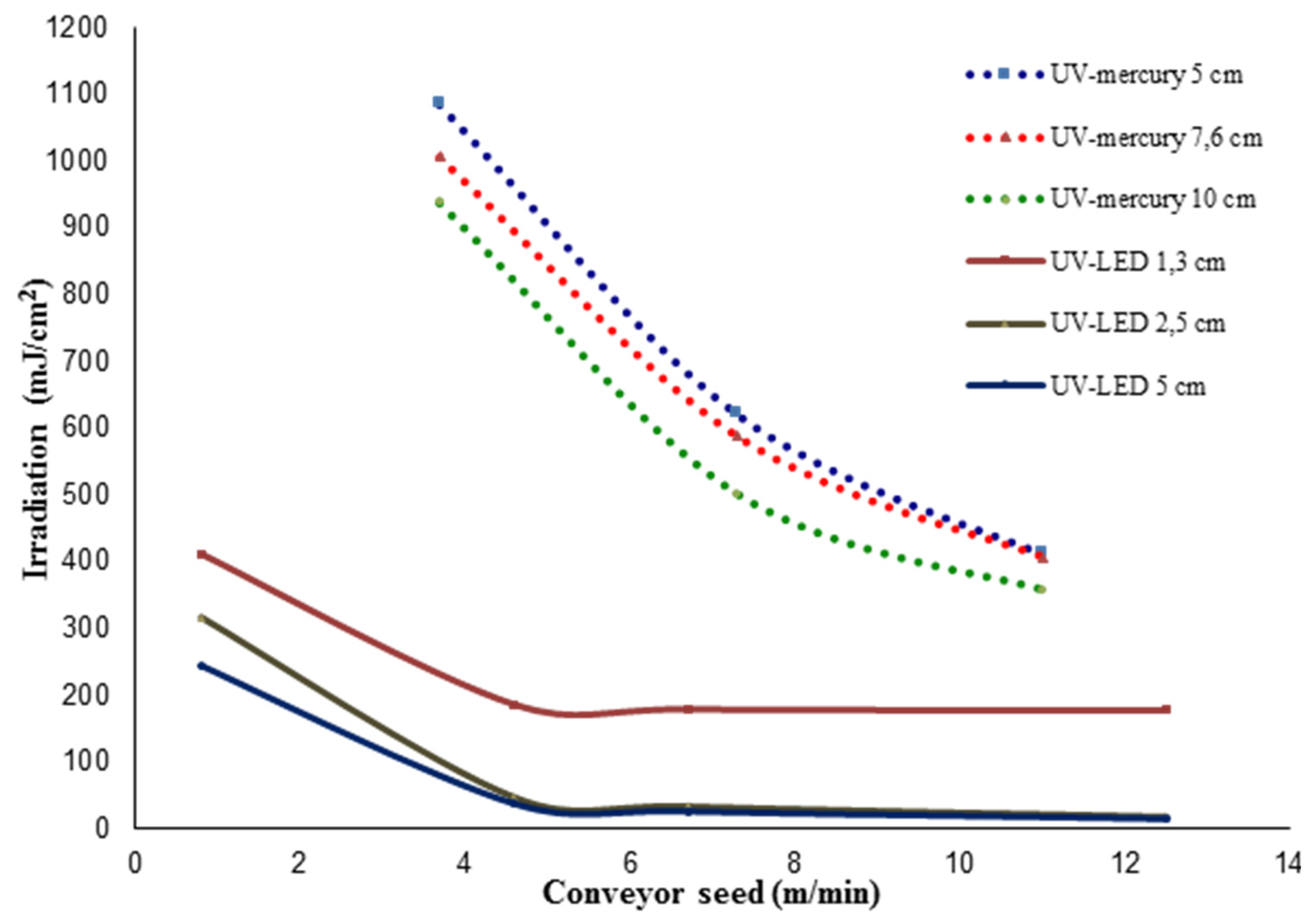
3.1.1. Lamp Irradiation

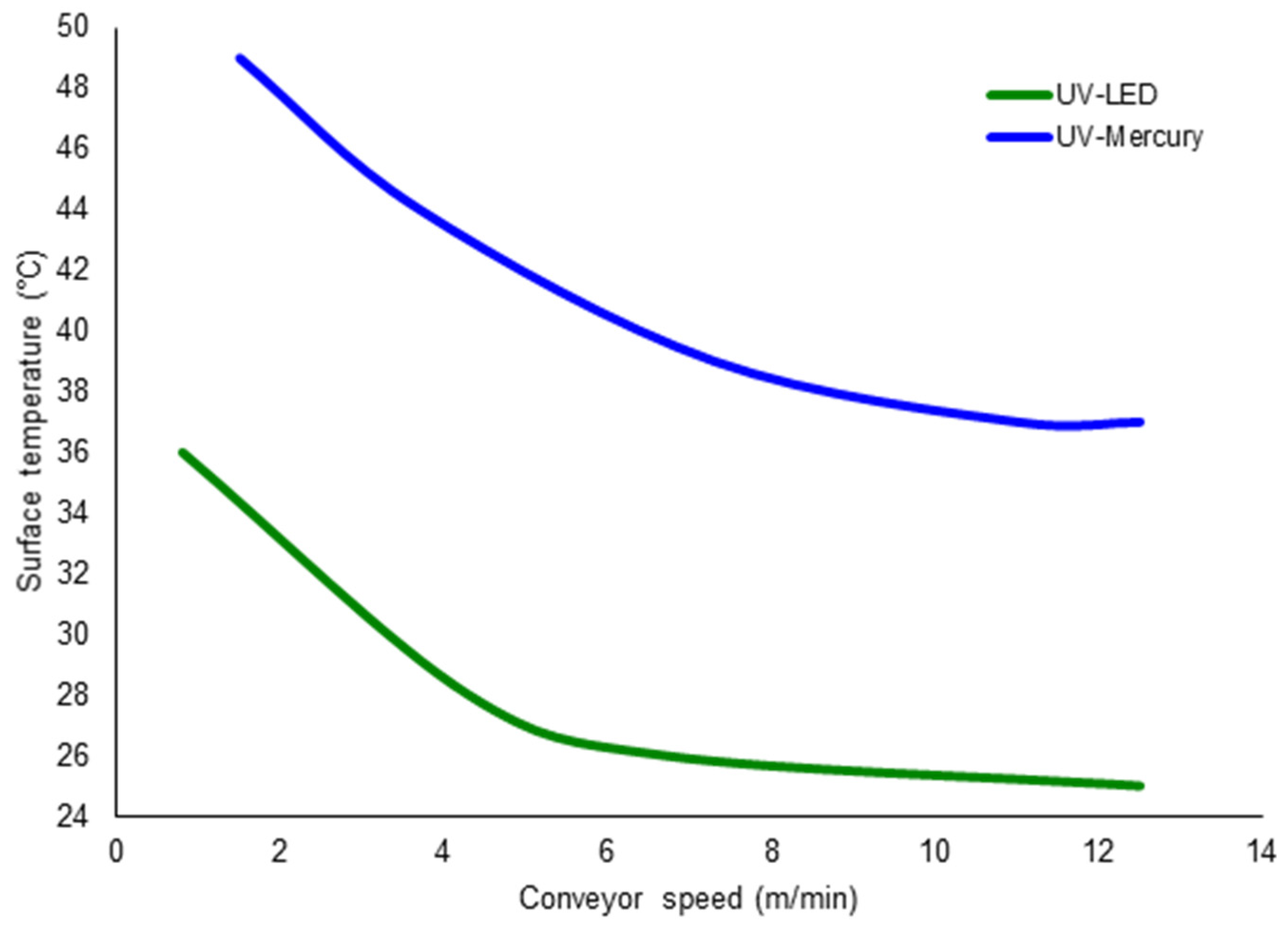
3.1.2. Surface Temperature

3.2. Coating Characterization
3.2.1. Conversion Percentages
| Formulations | Conversion Percentages (%) |
|---|---|
| A | 37 ± 7 |
| B | 38 ± 6 |
| C | 21 ± 7 |
| D | 23 ± 6 |
| E1 | 15 ± 8 |
| E2 | 78 ± 4 |
| F | 67 ± 3 |
| G | 78 ± 4 |
| H | 21 ± 6 |
| I | 54 ± 8 |
| J | 71 ± 3 |
| K | 26 ± 5 |
| L | 48 ± 6 |
| M | 41 ± 4 |
| N | 65 ± 3 |
| O | 28 ± 7 |
| Formulations | Conversion Percentages (%) |
|---|---|
| 1 | 44 ± 5 |
| 2 | 43 ± 5 |
| 3 | 84 ± 4 |
| 4 | 92 ± 3 |
| 5 | 66 ± 3 |
| 6 | 93 ± 2 |
| 7 | 29 ± 6 |
| 8 | 43 ± 4 |
| 7a | 91 ± 5 |
| 8a | 92 ± 4 |
| 9a | 87 ± 3 |
| 10a | 73 ± 4 |
3.2.2. Mechanical Properties
Scratch Resistance Tests

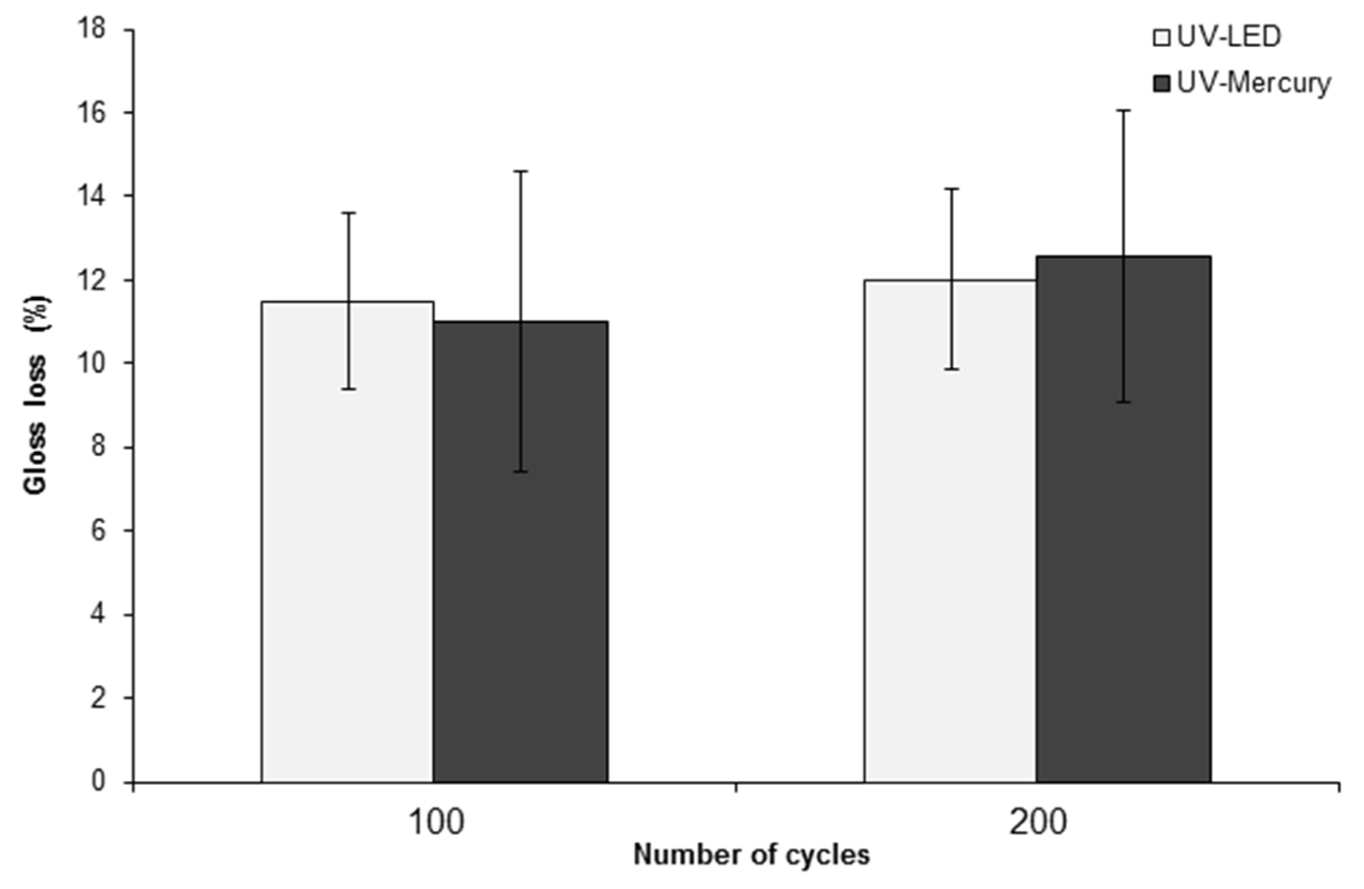
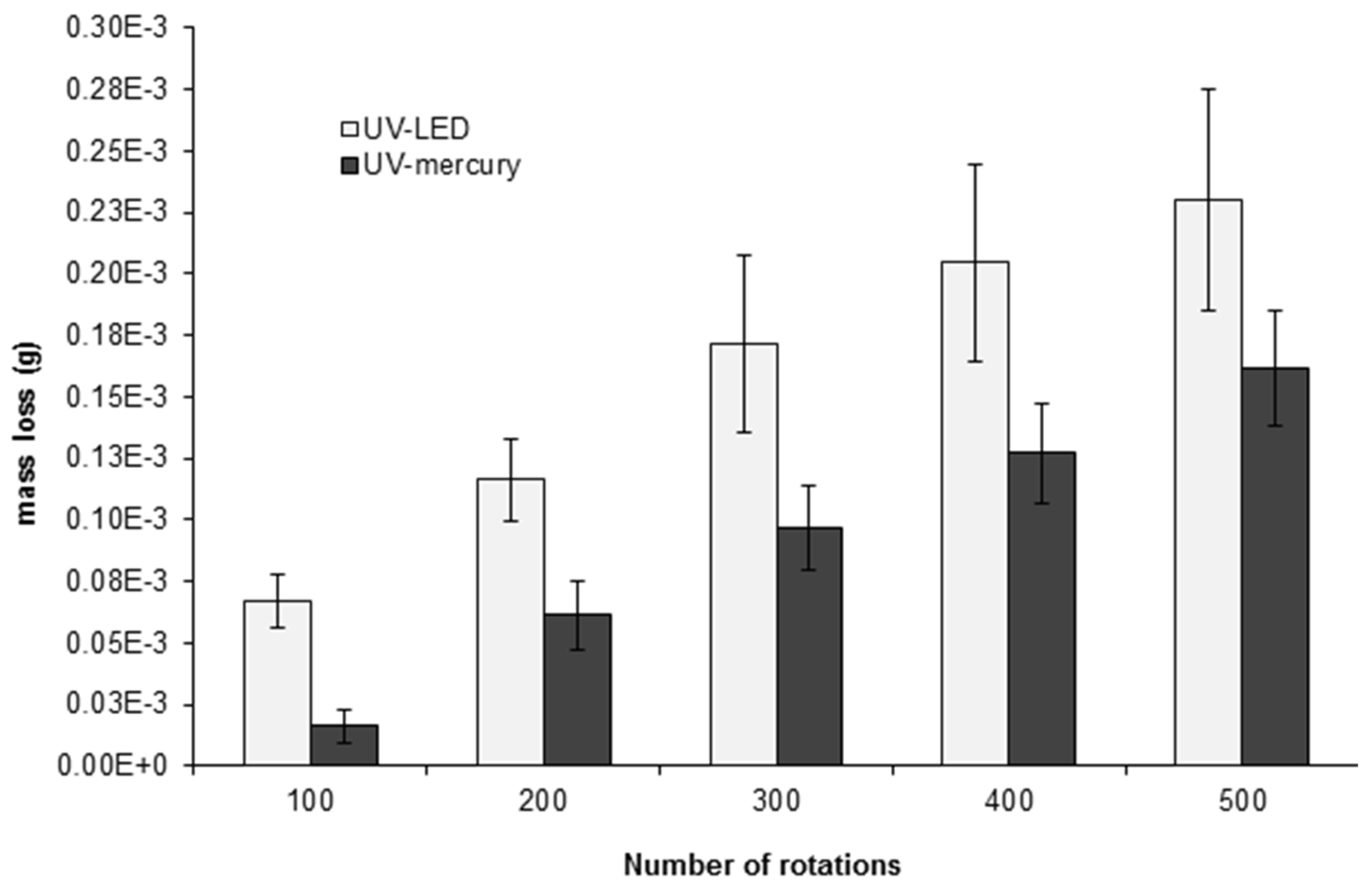
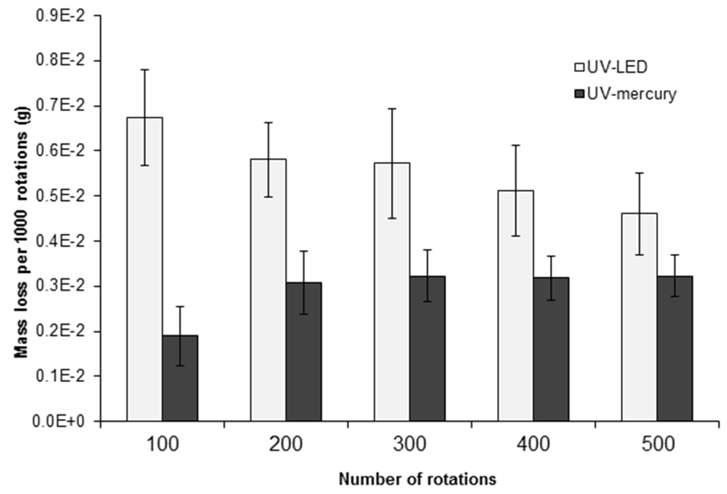
Abrasion Resistance Tests

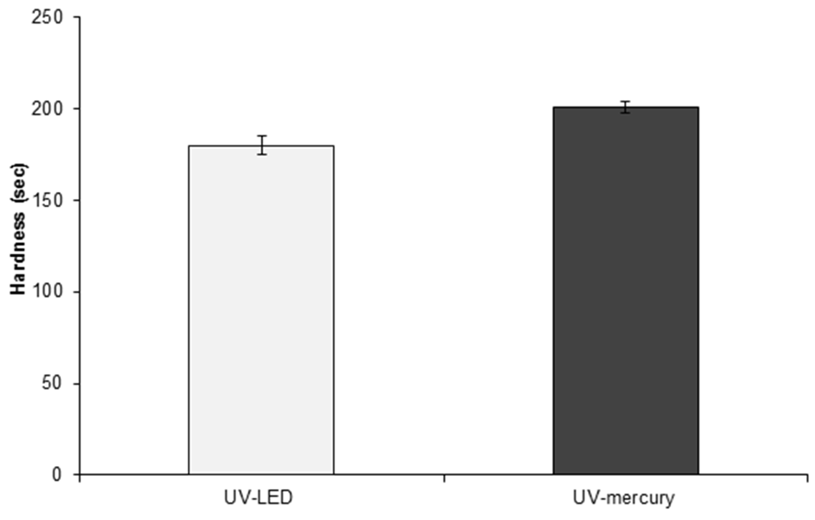
Hardness Tests
4. Conclusions
Acknowledgments
Author Contributions
Conflicts of Interest
References
- Coatings World. Available online: http://www.coatingsworld.com/contents/view_features/2008-04-04/radcure-coatings-market/ (accessed on 25 July 2015).
- Radtech the Association for UV/EB Technology. Available online: http://www.radtech.org/images/pdf_upload/UV-EBMarketTrends7.12.pdf (accessed on 25 July 2015).
- The North American Market for UV/EB Technology. In Proceedings of the Radtech UV/EB, Rosemont, IL, USA, 12–14 May 2014.
- Ross, J.S. UV&EB in the Flooring Industry—Reducing Greenhouse Gas Emissions & HAPs. Radtech Report. 2007. Available online: http://www.radtech.org/images/pdf_upload/UVandEBintheFlooringIndustry-ReducingGreenhouseGasandEmissionsandHAPS.pdf (accessed on 16 November 2015).
- Modjewski, R.J. UV Curing for Wood Applications, Radtech Report, 1999. Available online: http://www.radtech.org/images/pdf_upload/uvcurewoodapp.pdf (accessed on 16 November 2015).
- UV LED Curing Community. Available online: http://uvledcommunity.org/uploads/pdfs/Technote-UV-LED-print-guide-US_web.pdf (accessed on 24 June 2015).
- Anderson, D. UV-LED Report Summary. Available online: http://cordis.europa.eu/result/rcn/144779_en.html (accessed on 16 November 2015).
- Karsten, R.O. UV-LED Curing for Wood Coatings, Phoseon Technology p.7. Available online: http://www.phoseon.com/Documentation/uv led for wood coatings.pdf (accessed on 31 July 2015).
- Kiyoi, E. Wood Coating with UV-Led Curing: A Focus on Heat; Radtech Report; Available online: http://www.radtech.org/magazinearchives/Publications/RadTechReport/jun-2014/Wood%20Coating%20with%20UV-LED%20Curing-A%20Focus%20on%20Heat.pdf (accessed on 17 December 2015).
- Sitzmann, E.V. Critical Photoinitiators for UV-LED Curing: Enabling 3D Printing, Inks and Coatings. In Proceedings of the Radtech UV.EB West 2015, Redondo Beach, CA, USA, 10 March 2015.
- Locuffier, J. Photoinitiators for UV-Led Curable Compositions and Inks. Patent WO2011069947 A1, 11 June 2011. [Google Scholar]
- Landry, V.; Riedl, B.; Blanchet, P. Progress in organic coatings. Nanoclay Dispers. Eff. UV Coat. Curing 2008, 62, 400–408. [Google Scholar]
- Esen, D.S.; Karasu, F.; Arsu, N. The investigation of photoinitiated polymerization of multifunctional acrylates with TX-BT by Photo-DSC and RT-FTIR. Prog. Organ. Coat. 2011, 70, 102–107. [Google Scholar] [CrossRef]
© 2015 by the authors; licensee MDPI, Basel, Switzerland. This article is an open access article distributed under the terms and conditions of the Creative Commons Attribution license (http://creativecommons.org/licenses/by/4.0/).
Share and Cite
Landry, V.; Blanchet, P.; Boivin, G.; Bouffard, J.-F.; Vlad, M. UV-LED Curing Efficiency of Wood Coatings. Coatings 2015, 5, 1019-1033. https://doi.org/10.3390/coatings5041019
Landry V, Blanchet P, Boivin G, Bouffard J-F, Vlad M. UV-LED Curing Efficiency of Wood Coatings. Coatings. 2015; 5(4):1019-1033. https://doi.org/10.3390/coatings5041019
Chicago/Turabian StyleLandry, Véronic, Pierre Blanchet, Gabrielle Boivin, Jean-François Bouffard, and Mirela Vlad. 2015. "UV-LED Curing Efficiency of Wood Coatings" Coatings 5, no. 4: 1019-1033. https://doi.org/10.3390/coatings5041019