Article

Performance Testing of Suspension Plasma Sprayed Thermal Barrier Coatings Produced with Varied Suspension Parameters

1
Treibacher Industrie AG, Althofen 9330, Austria
2
Progressive Surface, Grand Rapids, MI 49512, USA
3
University West, Gustava Melins Gata 2, Trollhattan 461 86, Sweden
*
Author to whom correspondence should be addressed.
Coatings 2015, 5(3), 338-356; https://doi.org/10.3390/coatings5030338
Submission received: 17 June 2015 / Revised: 20 July 2015 / Accepted: 22 July 2015 / Published: 24 July 2015
(This article belongs to the Special Issue High Temperature Coatings)

Abstract

:
Suspension plasma spraying has become an emerging technology for the production of thermal barrier coatings for the gas turbine industry. Presently, though commercial systems for coating production are available, coatings remain in the development stage. Suitable suspension parameters for coating production remain an outstanding question and the influence of suspension properties on the final coatings is not well known. For this study, a number of suspensions were produced with varied solid loadings, powder size distributions and solvents. Suspensions were sprayed onto superalloy substrates coated with high velocity air fuel (HVAF) -sprayed bond coats. Plasma spray parameters were selected to generate columnar structures based on previous experiments and were maintained at constant to discover the influence of the suspension behavior on coating microstructures. Testing of the produced thermal barrier coating (TBC) systems has included thermal cyclic fatigue testing and thermal conductivity analysis. Pore size distribution has been characterized by mercury infiltration porosimetry. Results show a strong influence of suspension viscosity and surface tension on the microstructure of the produced coatings.

1. Introduction

Suspension plasma spraying (SPS) of yttria stabilized zirconia (YSZ) coatings have demonstrated a number of favorable properties when compared to air plasma spray (APS) or electron beam-physical vapor deposition (EB-PVD) coatings in terms of sintering resistance, low thermal conductivity, and cyclic lifetime [1]. The cyclic lifetime performance of SPS YSZ coatings can be attributed to columnar-type microstructures that mimic the strain tolerant behavior of EB-PVD coatings systems [2]. Common wisdom held that these strain tolerant, columnar microstructures were only possible by vapor deposition techniques, yet SPS utilizes air plasma spray-based equipment. Consequently, columnar SPS coatings are of great interest for TBC applications due to the potential cost savings relative to EB-PVD coatings [3].
The mechanism for generation of columnar coatings is understood to be related to the generation of very fine droplets in the suspension injection process and resulting small in-flight particles once the solvent has evaporated [4]. Particles on the order of a micron in size have relatively low momentum due to their small size. The particles are therefore influenced by the drag of the plasma stream in the boundary layer close to the substrate causing them to change trajectory; impacting the substrate in the molten or semi-molten state at a shallow angle. The behavior of such small particles can be understood using the Stokes Equation:
S t = ρ p d p v p μ g l BL
where ρp is the density of the particle, dp is the diameter of the particle, vp is the velocity of the particle, μg plasma viscosity, and lBL is the boundary layer thickness. Particles below 1 µm show low Stokes number, leading to a strong influence of plasma flow on trajectory [5]. The effect of shallow impact angle and shadowing of surface topographical features leads to the formation of columnar structures in the deposited coatings. VanEvery et al. [6] proposed changing microstructure types depend upon the size of the impacting particle with a transition from planar (APS-like) deposition to columnar coatings as average particle size decreases as shown schematically in Figure 1. Control of columnar microstructures is therefore dependent on the size of the droplet generated during the atomization of the suspension as this decides the size of the impacting particle that will form the coating.
Figure 1. Schematic of coating microstructure change with increased particle size.
Coatings 05 00338 g001
Atomization may be considered discretely from solvent vaporization as the former has been shown to occur an order of magnitude faster than the latter [7]. A number of factors influence the atomization of the suspension and size of droplets in the plasma stream. Plasma shear forces try to break up the suspension into finer droplets, whereas suspension forces resist plasma shear forces and prevent further break up [7,8,9]. The balance of these influences will determine the final droplet size. The break-up of a suspension in the plasma stream during thermal spray processing has been studied previously, though no definitive description of the process has been published to date. Fazilleau et al. suggested a droplet size formula based on surface tension that includes influences from plasma properties of density and velocity [7]. However, several factors are excluded from the formula. A more complete formula may be based on calculations originally developed for atomization of fuel in an environment for high-speed gas [10]:
D = ( 136 η σ 3 2 d 1 2 ρ a 2 ρ 1 1 2 u 4 ) 1 3
where D is the final atomized droplet size. η is the viscosity of the suspension in Pa·s, σ is the surface tension of the suspension, d is the initial droplet size (µm), (that may be inferred to be the size of the suspension stream), ρa is the density of the plasma, ρl is the density of the suspension, and u is the velocity of the plasma stream. The above equation provides a framework for understanding the relationships between the various process parameters influencing atomization, but the authors do not contend that this equation accurately models the dynamics of suspension stream atomization. An experimental study on the atomization of suspensions of YSZ particles in ethanol and water solvents has been conducted by Rampon et al. [11]. The study found that a ~50% increase in solvent surface tension produced a larger increase in the average droplet diameter than doubling the solvent viscosity. Thus, the results of Rampon et al. [11] suggest that Equation (2) correctly reflects the relative importance of surface tension and viscosity on droplet diameter, but the actual exponents on these terms may not be accurate for predicting the average droplet diameter of suspensions like those of this study.
From a coating production and design perspective, a number of suspension parameters are of interest to the end user. Increased solids loading of the suspension is of interest for possible increased deposition rates in coating production. The use of water versus ethanol as a solvent is of interest due to combustion risks associated with ethanol based suspensions. Smaller grains and pores in the microstructure may enhance coating properties such as thermal resistance, hardness, etc. Therefore, the powder particle sizes in the suspension may be of interest from a microstructure standpoint because it is believed that the scale of microstructural features may depend upon the primary suspension particles. The impact of such changes on suspension properties and coating microstructure will be investigated in this study. Therefore the plasma parameters have been kept constant together with injector orifice size and position in order to produce as near to identical spray conditions as possible. In order to demonstrate the difference in suspension factors on coating microstructure, a number of suspensions have been manufactured that will show differences in density, viscosity and surface tension.

2. Experimental

2.1. Coating Production

Substrates used for this study were all Hastelloy-X superalloy. Geometries of 25 mm × 25 mm × 1.6 mm were used for microstructure and thermal conductivity evaluation. 25.4 mm diameter round samples with a thickness of 6 mm were used for thermal shock testing. Thermo-cyclic fatigue samples were 50 mm × 30 mm × 4 mm rectangular test plates.
Bond coats were produced using the high velocity air-fuel (HVAF) spraying technique (Uniquecoat M3, Uniquecoat, Richmond, VA, USA). HVAF coatings had displayed promising lifetime results in previous testing and so were considered a suitable bond coats for this study [12,13]. The powder used to produce the bond coats was AMDRY 386-2 (Oerlikon Metco, Wohlen, Switzerland), a proprietary NiCoCrAlY material with additions of Hf and Si. Bond coats for all test samples were deposited during one spray occasion in order to reduce any variability in bond coat surface topography and oxidation performance. No further surface treatment was performed on the bond coats before SPS coating deposition.

2.1.1. Suspensions

Several suspensions were prepared for the project and are summarized in Table 1. The five suspensions labeled with a “T” were prepared by Treibacher Industrie AG (TIAG) for testing together with two suspensions sourced from other manufacturers (labeled C). The solvent used for the suspensions was ethanol, with the exception of sample C2, which was a water-based suspension. Feedstock materials consisted of 8 wt % yttria partially stabilized zirconia, apart from suspension C1, which was fully-stabilized zirconia with 14 wt % yttria. In general the suspensions may be grouped according to their mean particle size in suspension: (1) the nano-scale suspensions, T1 and C2, which have roughly the same mean particle size but different solvents; (2) the 200 nm suspensions, T2, T3, and T4, which vary in solids loading from 17 wt % to 34 wt %; and (3) the 500 nm suspensions, T5 and C1. Median particle size of the suspension was analyzed using a Microtrac X100 (Microtrac GmbH, Krefeld, Germany) operating in full range mode. Nano suspensions T1 and C2 were measured using a BI-XDC X-ray centrifuge particle analyzer (Brookhaven Instruments Corp., Holtsville, NY, USA). Suspension density is also displayed as it was recorded from the Coriolis meter within the suspension feed system. It can be noted that the density of the suspensions reflects the solid loading T1–C1. In the case of the water-based suspension (C2), the density is higher than that of the other suspensions due to the higher density of water relative to ethanol.
Table 1. Summary of experimental suspensions and coating deposition behavior.
SuspensionSolids LoadingParticle D50 (nm)Suspension Density (g/cc)Deposition Rate (µm/pass)Coating Thickness (µm)
T125%45 nm1.0033.4344
T233%200 nm1.1045.3531
T325%200 nm1.0293.6362
T417%200 nm0.9412.2221
T525%500 nm1.0313.8378
C125%400 nm1.0493.7374
C225%45 nm1.2424.8484

2.1.2. Suspension Atomization Parameters

Rheology for the experimental suspensions was analyzed using an (MCR 301 Rheometer, Anton Paar, Austria). From the viscosity data in Figure 2, the nano-suspension, T1 exhibits the highest viscosity, though with shear thinning behavior. The 200 nm suspensions T2, T3 and T4 display lower viscosity than the nano-suspension. Differences between the 200 nm suspensions can be correlated according to solids content, where higher loading of 33% for the T2 results in higher viscosity relative to suspension T3 (25% solids) or T4 (17% solids). The 400–500 nm suspensions T5 and C1 can be observed to have the lowest viscosity; in the range 1.8–2 mPa·s. Finally, the water based nano-suspension C2 has a viscosity, which is four to eight times smaller than that of the ethanol-based nano-suspension T1 over the measured shear rates. However, as discussed previously, the suspension surface tension will impact atomization. While the surface tension values for the individual suspensions were not measured in this study, values have been reported in literature for water- and methanol-based suspensions containing a YSZ powder loading of 20 wt % [11]. That study found a surface tension value for the YSZ in water suspension of 0.038 N/m and a corresponding value for the YSZ in methanol suspension of 0.025 N/m. Equation (2) also shows suspension density influences the atomization process. In the case of the suspensions of this study, the influence of suspension density is deemed to be a minor factor because, as can be seen in Table 1, the density values varied by no more than 32%.
Figure 2 shows that significant viscosity differences exist between the T1, T3, and T5 suspension data. Median particle size was the only variable changed between these three suspension formulations. Therefore, since the injection and plasma parameters were kept constant for the experiments, a comparison of the coatings produced from T1, T3, and T5 will provide the clearest insight into the influence of suspension viscosity on microstructure formation.
Figure 2. Viscosity of experimental suspensions.
Coatings 05 00338 g002

2.1.3. SPS Sample Production

SPS layers were deposited using the 100HE plasma spray and LiquifeederHE systems (Progressive Surface, Grand Rapids, MI, USA). For all of the suspensions, coatings were deposited using the same spray conditions in order to examine the effects of changing suspension characteristics on the resulting coatings. Suspension was fed using a peristaltic pump to the gun and injected though a 200 µm diameter coherent stream injector, no atomization of the suspension occurred prior to the stream reaching the plasma plume. A suspension feed rate of 45 mL/min was maintained via digital feedback control between the peristaltic pump and a Coriolis meter measuring the suspension flow rate. Total power output of 105 kW was used with plasma gas flows of 85 SLM Argon, 57 SLM Nitrogen and 57 SLM Hydrogen [14]. Stand-off distance for the plasma torch was set at 70mm, as illustrated in previous work [12]. Coating was performed using a rotating fixture with the substrates orthogonal to the spray direction. For each suspension all substrates were coated during a single spray run to minimize the potential of top coat variations between the different test specimens produced using a particular suspension. Since the number of robot strokes for deposition was maintained constant at 100 in all spray runs, variations in coating thickness occurred due to deposition efficiency and rate differences between different suspensions. Furthermore, the spray conditions were developed using the T1 suspension in a previous study (see Table 1) [12]. Thus, these conditions may not represent the optimal spray parameters for the other suspensions tested.

2.2. Porosity Measurement

The conventional method of assessing porosity content within coatings relies on stereological analyses of the area fraction of pores within cross-sectional images. However, such techniques are not well-suited to assessing SPS coatings because of the small pore size (microns to nano scale) and the fact that larger porosity features such as cracks or inter-columnar gaps must be included together with the intra-columnar pores. Consequently, mercury infiltration porosimetry (MIP) was used to assess the overall open porosity content of the SPS coatings.
Samples for MIP testing were cut from 25 mm × 25 mm plates and placed in a bath of Aqua Regia acid. The acid dissolves the bond coat at the interface with the ceramic, thus detaching the ceramic coating. The samples are subsequently washed in a water bath and dried in an oven to remove water content. Mercury analysis was performed using a Poremaster 60 GT (Quantachrome, Germany). During the MIP analysis, mercury is forced into a sample of the SPS coating using an applied pressure. Mercury’s high surface tension and consequently low degree of wetting on most materials means that an exterior pressure is required to force mercury into the coating porosity. The pressure level required to force mercury into the coating structure may be correlated to the size of the porosity feature.

2.3. Thermo-Cyclic Fatigue Testing

Thermo-cyclic fatigue (TCF) testing is a lifetime testing technique that primarily assesses oxidation driven failure in a TBC system. Test samples are placed in a furnace at 1100 °C for 60 min, after which they are removed from the furnace to a cooling stage. At the cooling stage, the samples are cooled with compressed air for a period of 10 min. As such, the test is a combination of thermal shock on quench cooling and stress generated by oxide growth. During the cooling period, the samples are photographed by the test rig and may be visually inspected. After the prescribed cooling period, the samples are returned to the furnace. The testing is continued until 20% surface spallation of the ceramic coating from a sample, judged from the recorded images. After “failure” has occurred, the sample may be removed from the furnace and prepared for microstructure evaluation. A minimum of 3 samples from each suspension type underwent TCF testing.

2.4. Thermal Diffusivity Analysis

Thermal diffusivity of complete coating systems was assessed by the laser flash method (LFA), utilizing a LFA 427 (Netzsch Thermophysic, Selb, Germany). Testing involves the use of an infrared laser pulse of known duration impacting the sample rear face. An IR sensor then detects the increase in temperature on the coated face of the sample. Thermal diffusivity is then calculated from the half time for total temperature increase by the following relation [15]:
α = 0.1388 L 2 t ( 0.5 )
where α is thermal diffusivity, L is the total sample thickness, and t is the detected time taken for temperature increase. During this test, the coatings are evaluated as a three-layer system (substrate, bond coat and ceramic layers). The properties of the substrate and bond coat having been being measured in earlier studies [16,17]. Thermal conductivity of the ceramic SPS layer is then calculated using Proteus analysis software (Netzsch Thermophysic, Selb, Germany) from the measured diffusivity of the complete coating system and experimental data from the individual materials that compose each layer. The specifics of the test procedure have been discussed previously [17]. Samples used for LFA measurement are water jet cut as 10 mm discs from coated 25 mm square plates, with two samples being cut from each plate. A total of 4 samples were measured for each coating/suspension type for statistical reasons. The bulk density of the ceramic layer was calculated by a water infiltration method according to ISO 10545-3 under vacuum conditions [18].

3. Results

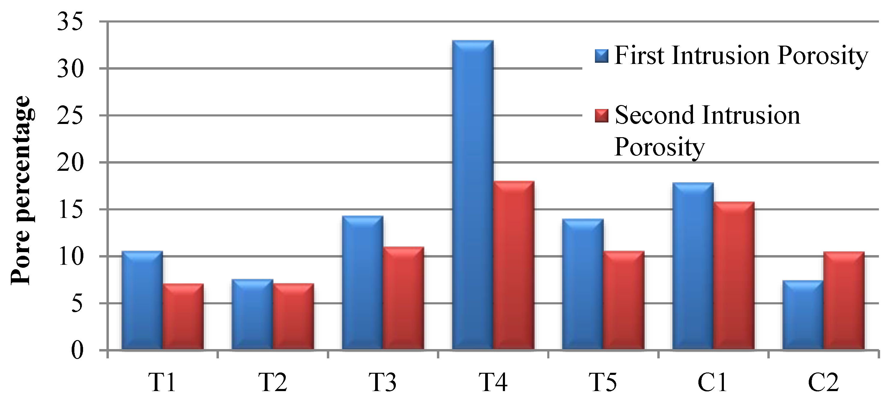
3.1. Mercury Porosimetry

The data shown in Figure 3 give two sets of values corresponding to the low- and high-pressure regimes. These separate curves give information on the different scale of porosity within the coating. First infiltration is related to the easily accessible pores within the structure. These can be considered the vertical cracks or inter columnar spaces and large scale pores. The second infiltration relates to the finer scale pores within each column or segment. In addition to the porosity detected here, there is also an amount of closed porosity that is not accessible to the mercury. The amount of closed porosity is around 7%–12% for the coatings presented here. This closed porosity is also of importance, as it contributes to the thermal insulation of the coatings.

3.2. Microstructure Analysis

Micrographs of the coatings produced are displayed in Figure 4. The nano-suspension T1 produces coatings that are consistent with previously published work [12]. The microstructure is termed a cracked-columnar structure (Figure 1), a transitional structure between fully columnar and segmented/vertically cracked microstructures. Inter-pass porosity boundary (IPB) layers can be seen within the structure of the individual segments. IPBs are formed by particles treated in the periphery of the plasma core; deposited at the leading and trailing edges of the plasma plume as it traverses the substrate. Particles treated in the cooler plasma periphery region will have lower velocity and temperature than material treated in the plasma core. As a result, this material deposits in the semi-molten or re-solidified state and lower velocity, leading to layers of increased porosity. The microstructure suggests the droplets produced when spraying the T1 suspension experience some influence from plasma drag at the substrate surface, though not sufficient to generate a fully columnar coating. Based on viscosity measurements alone, the T1 nano-suspension should display the largest suspension fragment size of the suspensions studied here.
Figure 3. Coating porosity by MIP technique.
Coatings 05 00338 g003
Figure 4. T1 coating, nano-suspension.
Coatings 05 00338 g004

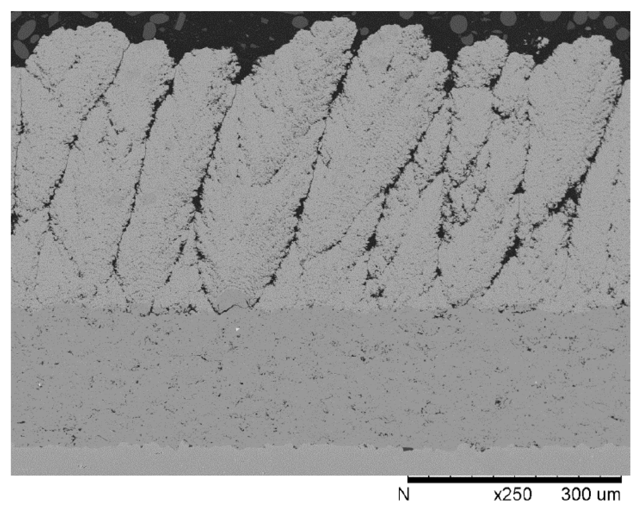
3.2.1. Influence of Solids Loading

Coatings from the three 200 nm suspensions can be observed in Figure 5 with the coatings in descending order of solids content (T2–T4). It can be observed the decrease in thickness and transition in microstructure when comparing T2, T3 and T4 suspensions. These changes can be related to the solids loading of the suspension and its influence on suspension viscosity. As all coatings were produced under the same spray conditions with identical number of spray passes, higher solids load suspensions will give greater material deposition per pass and thus greater total thickness for a given number of passes.
Figure 5. Coatings: (a) T2, 33% solids load; (b) T3, 25% solids load; and (c) T4, 17% solids load.
Coatings 05 00338 g005
Comparison of coating thickness between the T1, T2, and T3 samples shows that the T2 (33% solids) sample was ~50% thicker than the 25% solids coatings, yet the T2 suspension contained only 32% more powder than the T1 and T3 suspensions. Therefore, it appears that increasing the powder concentration from 25 wt % to 33 wt % increased the deposition efficiency. The increase in thickness per pass and deposition efficiency would be of interest to increase the processing rate of SPS on components. However, it is clear that increased solids load would result in different coating microstructures if no measures are taken to alter the plasma conditions.
It can be observed from the micrographs that, as solid loading decreases from 33% (T2), to 25% (T3) to 17% (T4), the microstructure of the coatings shifts from more dense, vertically-cracked to progressively columnar in nature. The change in microstructure type is consistent with a reduction in the median size of the particles forming the coating as powder concentration is reduced. Changing the suspension powder concentration will alter the size of the coating forming particles via two mechanisms:
(1)
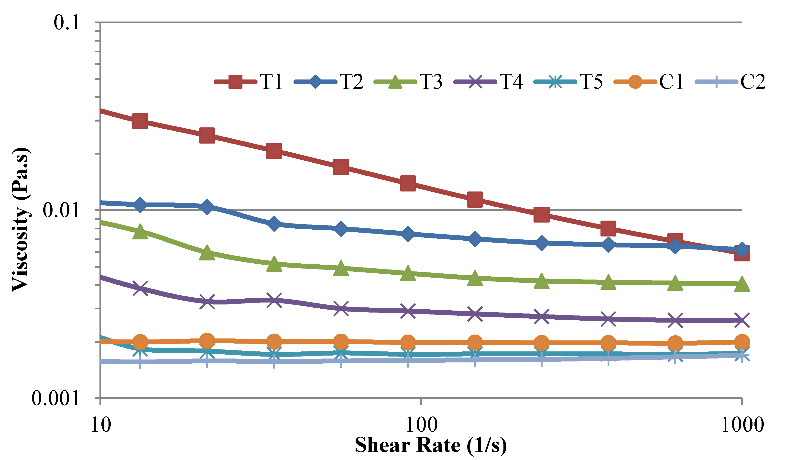
Reducing the suspension solids loading reduces the suspension viscosity as shown in Figure 2 for the 200 nm suspensions. The reduced viscosity will allow easier atomization and increase the production of the smallest suspension droplets during fragmentation according to Rampon et al. [11] and predicted by Equation (2).
(2)
As a secondary effect, increasing the powder solids load within a suspension increases the mass of powder contained within each suspension droplet produced during the fragmentation process. A larger suspension droplet will also contain more powder particles, leading to a larger YSZ particle after solvent evaporation and subsequent melting of the ceramic.
As discussed in the introduction, larger YSZ particles will experience less influence for the plasma drag within the boundary layer at the surface of the sample due to their higher momentum; thus leading to less columnar coatings [6]. It can be noted from MIP data in Figure 3 that the consequence of increasing impacting droplet size (due to higher solids load) also reduces the coating total porosity. Particularly, the impact is seen on the large-scale porosity features such as large pores or column gaps. In the case of coating T4 the level of large-scale porosity in the form of column gaps is increased dramatically over the other 200 nm coatings due to the in-homogenous structure and thickness of the T4 coating.

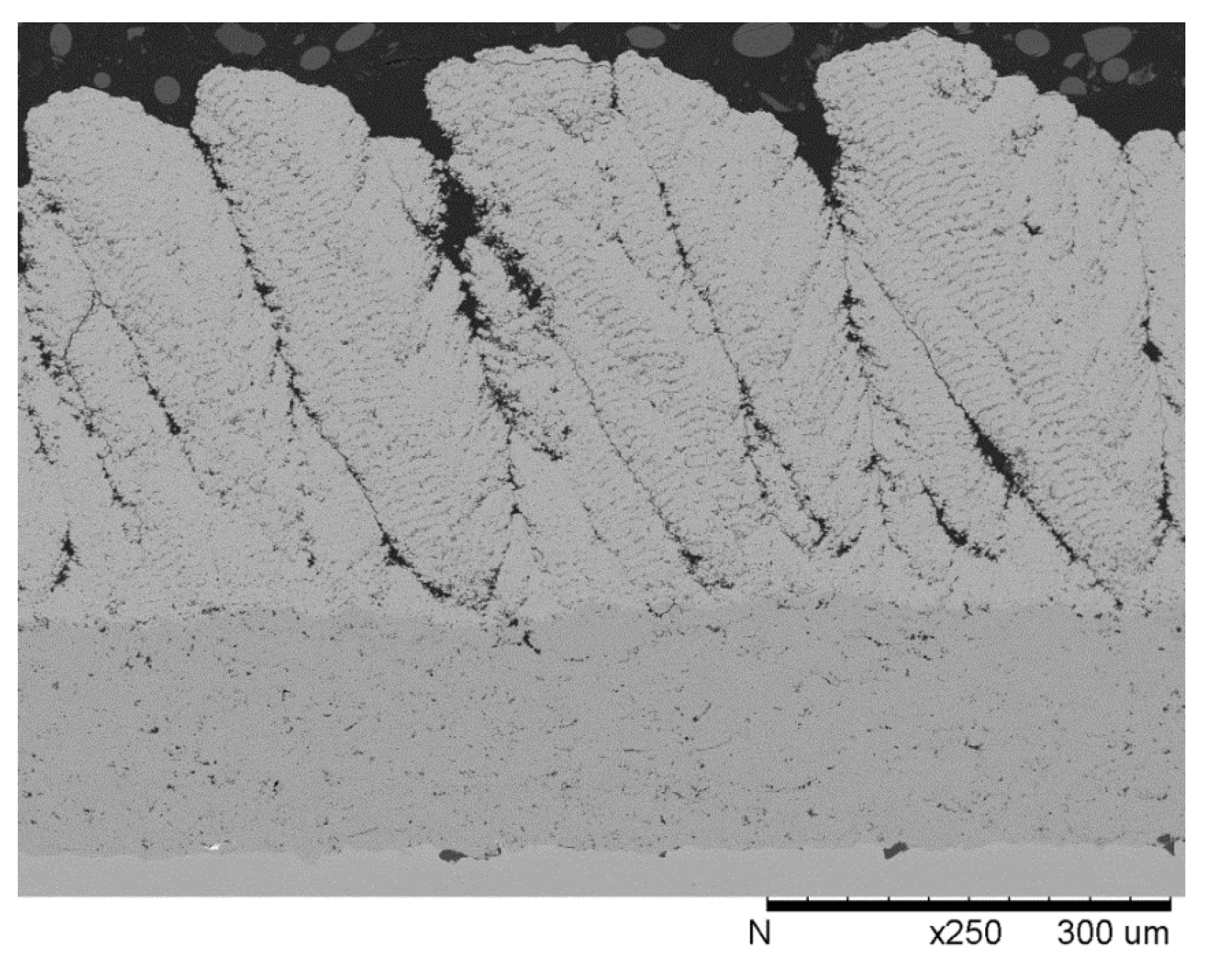
3.2.2. Comparison of Sub-Micron Suspensions

The T5 coating microstructure (Figure 6) contains more uniform columnar structures than those found in the coatings produced from the other 25 wt % powder suspensions, T1 and T3. This fully columnar structure suggests the T5 suspension underwent stronger fragmentation by the plasma, producing smaller YSZ particles than the T1 or T3 suspensions. An analysis of the T1, T3, and T5 data displayed previously in Figure 2 shows that the suspension viscosity decreases significantly as the median particle size increases. For a given solids loading, suspension containing larger particles will have a smaller amount of ceramic surface area in contact with the solvent. This leads to reduced influence from van der Waals and electrical double layer forces within the suspension. Reduced forces give the suspension a lower viscosity. Unlike APS, powder particle size is only indirectly influencing SPS coating microstructure as the properties of the suspension (viscosity and surface tension) control the size of the atomized droplet and thus of final depositing particle. As a result, finer scale structures do not necessarily result from smaller median size ceramic particles in suspension, the suspension parameter’s and plasma conditions control the size of the depositing particles.
The C1 sample shown in Figure 7 has a similar structure and comparable thickness to the T5 sample (Figure 6). This similarity is logical as both suspensions have the same solid loading and comparable median particle sizes of the powder in the starting suspensions—C1: D50 = 0.4 µm, T5: D50 = 0.5 µm. However, relative to the T5 microstructure, an increased amount of inter-pass porosity bands (IPBs) are observable within the C1 microstructure. This is confirmed from MIP data presented in Figure 3 where for C1 the percentage of both large and small-scale pores is greater than for T5.
As discussed previously, IPBs are produced by the deposition of material treated in the plasma plume periphery rather than in the plume core. Suspension/YSZ droplets entrained in the plume periphery are more likely to be slower and less molten than ones entrained in the plasma core because interactions with the surrounding atmosphere cause the temperature and velocity of the plasma to decrease with radial distance from the plume centerline. Coatings T5 and C1 have approximately the same thickness but C1 has greater amount of IPBs. This suggests that a greater quantity of material was treated in the plasma periphery rather than the plasma core. Thus, relative to the T5 sample, the increased presence of IPBs in the C1 sample suggests that the C1 suspension was less effective at penetrating into the plasma core. The possible cause of the lower penetration into the plasma core may be related to the slightly smaller median particle size for the C1 suspension relative to the T5 suspension.
Figure 6. T5 coating, 500 nm suspension.
Coatings 05 00338 g006
Figure 7. C1 coating, 400 nm suspension
Coatings 05 00338 g007

3.2.3. Influence of Suspension Solvent

The C2 coating microstructure (Figure 8) contained more horizontal cracks and a more planar top surface than the other coatings. Additionally, the C2 MIP data set is the only one in Figure 3 to show more porosity during the second, higher pressure intrusion than the first. This finding suggests that the majority of the open porosity within the C2 sample exhibited a more tortuous and/or higher aspect ratio (i.e., more crack-like) morphology than that of the other coatings. Taken together, the above findings indicate that the C2 coating is less like a columnar microstructure and more like a vertically-cracked APS microstructure than any of the other coatings produced in this study. The C2 suspension contained the same powder concentration and median particle size as the T1 suspension (Table 1). However, these two suspensions utilized different solvents-ethanol for T1 and water for C2. The decrease in columnar characteristics of the C2 coating relative to the T1 coating (Figure 4) supports the conclusion that switching from an ethanol to a water solvent produced YSZ particles that were larger and less susceptible to plasma drag influence during deposition.
Figure 8. C2 coating, nano-suspension in water.
Coatings 05 00338 g008
The study by Rampon et al. reports that the atomization of a water-based YSZ suspension tends to produce a significantly larger average and a tighter distribution of droplet sizes than an alcohol-based YSZ suspension with the same powder concentration having a threefold higher viscosity [11]. This effect is linked to the surface tension of the suspension solvent. Water based suspensions have a greater surface tension than ethanol and thus resist atomization in the plasma stream more strongly (Equation (2)). Furthermore, Rampon et al. found that water-based suspensions injected into plasma, produced faster particle speeds with some reduction in particle temperature. The increased speed is attributed to the higher momentum of a larger droplet being more able to penetrate into the central, fastest part of the plume and therefore attain greater acceleration from the plasma [11]. Therefore, compared to the T1 suspension, C2 could be expected to produce YSZ droplets that were overall larger and faster than any of the other suspensions tested.
The properties of the solvent may be considered to have an impact on the plasma plume itself. Fazilleau et al. reports that plasma plume temperature is reduced slightly with the injection of the liquid [7]. However, calculations of Pateyron et al. indicate thermal conductivity of the plasma is enhanced by ethanol or water solvents due to their dissociation, thus allowing better heat transfer to the particles in flight [19]. It can be understood that water based suspensions require approximately 3.2× greater energy to vaporize than ethanol [7]. Therefore, larger water based suspension droplets may require longer flight time in the plasma before the solvent is evaporated and the ceramic particle can be melted.

3.3. Thermal Conductivity Results

Figure 9 shows the thermal conductivity data for the coatings of this study. It can be observed that the standard deviation for the samples is very low, indicating reliability of the measurement between samples. Within the four samples tested for each coating, the measurements exhibited a standard deviation on the order of 0.01 W·m−1K−1; this level of precision results in all but the T2 and C2 coating samples displaying statistically different values for thermal conductivity. Thus, hypotheses can be proposed on how the unique aspects of the coating microstructures influenced thermal conductivity. Analyzing the results between coatings shows that the thermal conductivity generally decreases with increasing total open porosity, which can be determined from the MIP data in Figure 3. This trend is expected since coating density, which is inversely related to coating porosity, is multiplied by the thermal diffusivity and specific heat capacity to calculate thermal conductivity.
Figure 9. Thermal Conductivity results.
Coatings 05 00338 g009
The microstructure of the C1 coating may be compared to the T5 coating in Figure 6 and Figure 7, respectively. However, the C1 coating has roughly 30% lower thermal conductivity than the T5 coating. The lower thermal conductivity can be related to two aspects of the C1 coating:
(1)
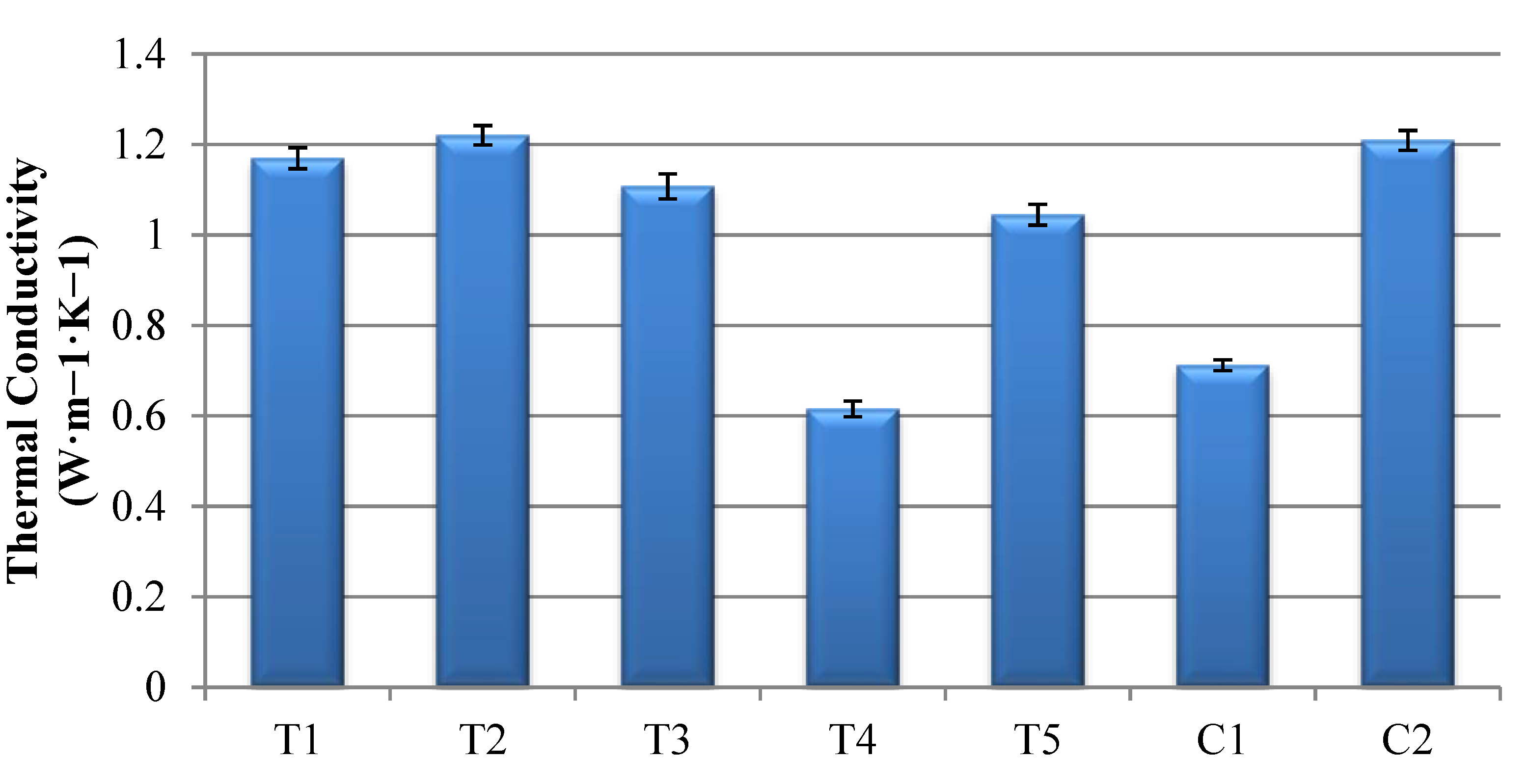
The C1 coating was formed from YSZ powder with 14 wt % yttria, whereas all other suspensions contained YSZ powder with 8 wt % yttria. The incorporation of yttrium atoms into the zirconia lattice requires the generation of oxygen vacancies. These point defects produce scattering of the lattice waves (phonons) that transport the thermal energy through the coating [20,21,22]. Thus, compared to the other samples, the 75% increase in yttria within the C1 samples should have reduced the thermal diffusivity of these coatings.
(2)
Additionally, interactions between phonons and pore boundaries can disrupt phonons transport through the coating. Hence, the porosity that most effectively reduces thermal diffusivity is that with the most area oriented perpendicular to the direction of heat transfer [23]. Therefore, higher porosity level in the form of IPBs within the C1 coating, and which ran roughly perpendicular to the primary heat transfer direction, will have increased the effectiveness of the porosity within this coating at reducing thermal conductivity.
Thermal conductivity results for the T3 and T5 coatings are comparable in level. Both coatings were produced from a 25% solids suspension but an average particle size of 200 nm and 500 nm respectively. While the coating microstructures are different between the coatings; comparison of the MIP porosity shows these coatings to have broadly similar porosity levels. Compared to the 25% solids load suspensions, the T2 sample with 33% solids load, displays a higher thermal conductivity than all other ethanol based suspension coatings. This may be expected due to the lower level of total porosity within the coatings detected during MIP testing.
The relatively low thermal conductivity of coating T4 (17% solids) is not in-line with the expected trend when comparing the drop in conductivity from coating T2 to T3 (33% solids to 25% solids). However, the MIP porosity data in Figure 3 demonstrates that coating T4 had dramatically increased levels of large scale porosity when compared to the other 200 nm suspension coatings, leading to greater insulating influence of coating porosity. Similar large reductions in thermal conductivity have been noted for APS coatings by incorporation of large scale globular pores [16,17].
The T1 and C2 nano suspension coatings exhibited equivalent total MIP values, but the average thermal conductivity of the C2 samples was marginally higher than that of the T1 samples. As discussed in the previous section, evidence supports the idea that the C2 coating was produced by the deposition of droplets that were larger, faster, and followed paths, which were more orthogonal to the substrate than those produced from the ethanol based suspensions. The faster impact speed of larger droplets for the C2 coating may have resulted in better cohesion within the coating, generating more fine scale pores and less large scale pores than the T1 coating. This would lead to better heat conduction though the thickness of the ceramic layer.

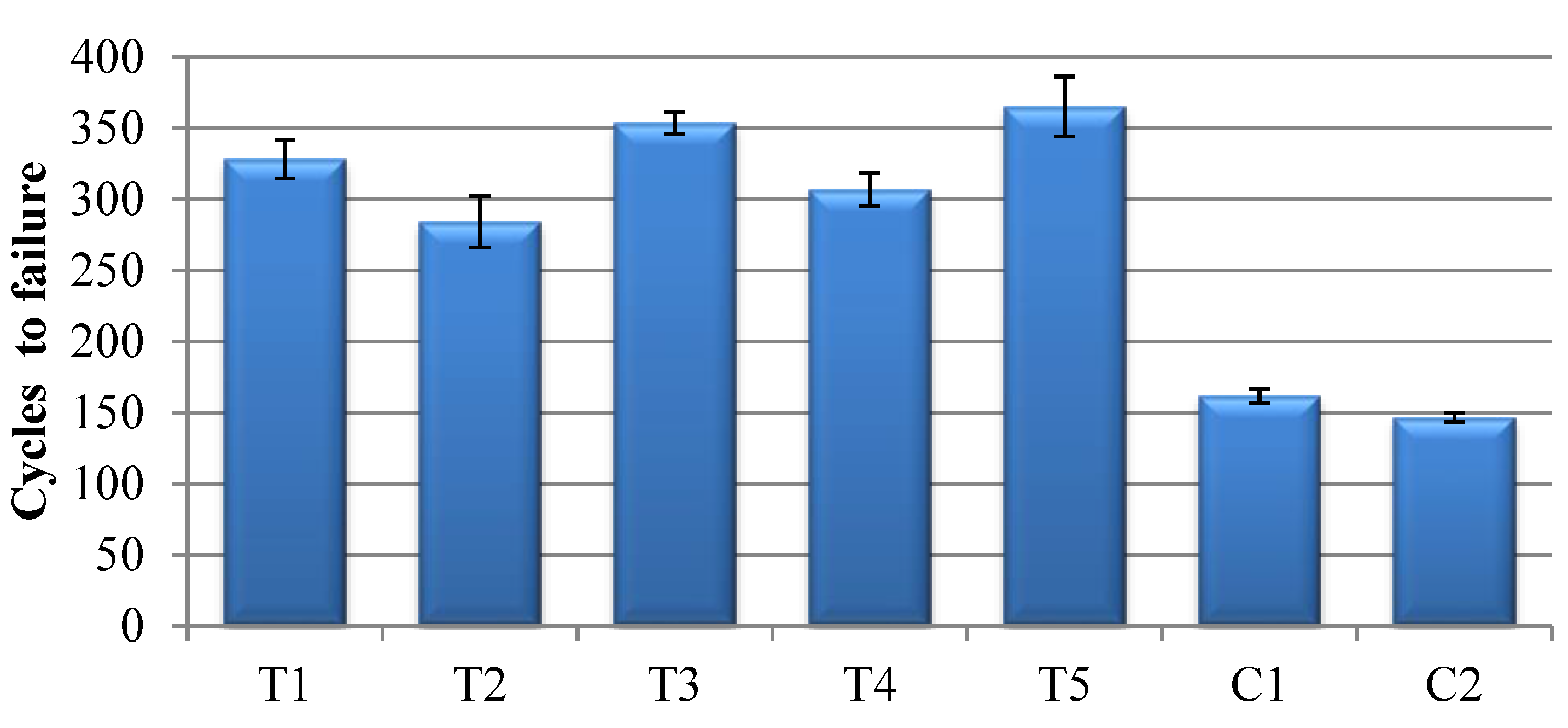
3.4. Thermo-Cyclic Fatigue

Thermo-cyclic fatigue performance of a TBC coating ultimately depends on the oxidation rate of the bond coat used, with the ceramic layer having a secondary effect on lifetime [24]. However, in this study, as all bond coats were identical, any differences in performance of the various test samples can be attributed to the influence of the SPS ceramic layer on overall lifetime. It can be observed in Figure 10 that the TCF lifetime of the 25 wt % TIAG suspensions is fairly consistent. It is notable that both the high and low solid concentration TIAG suspensions (T2 and T4) produce lower TCF lifetimes than the 25 wt % systems. This decrease may be connected to fact that the spraying conditions were optimized around the 25 wt % T1 suspension. The C1 and C2 coatings TCF lifetimes that were less than half of those determined for the TIAG 25 wt % systems. These decreases are the consequence of atomic and microstructural differences compared with the T-series coatings. Though C1 has a similar structure to T5, the use of fully stabilized YSZ in the C1 suspension lowers the coating toughness, making it more susceptible to cracking than the partially-stabilized zirconia T5 coating. In the case of the partially-stabilized zirconia C2 samples, the vertically-cracked microstructure is clearly less strain tolerant than the T-series columnar microstructures with same YSZ composition.

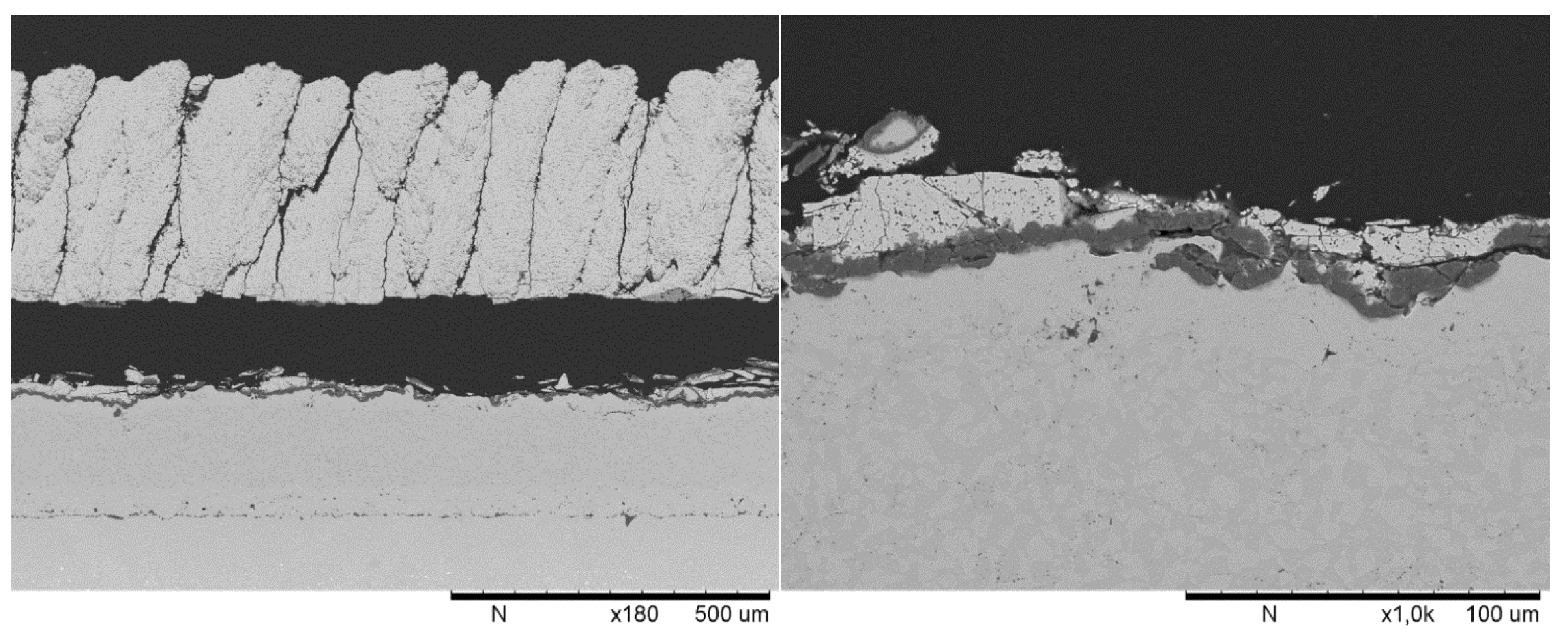
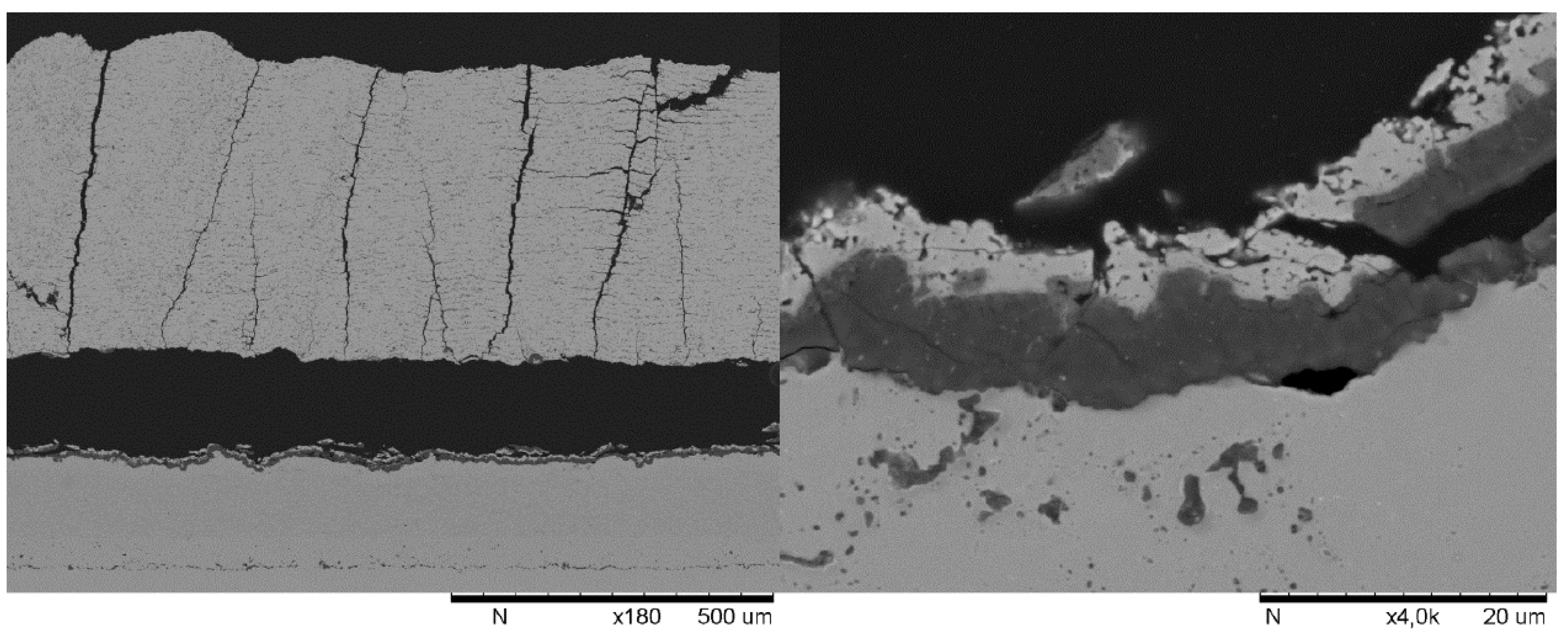
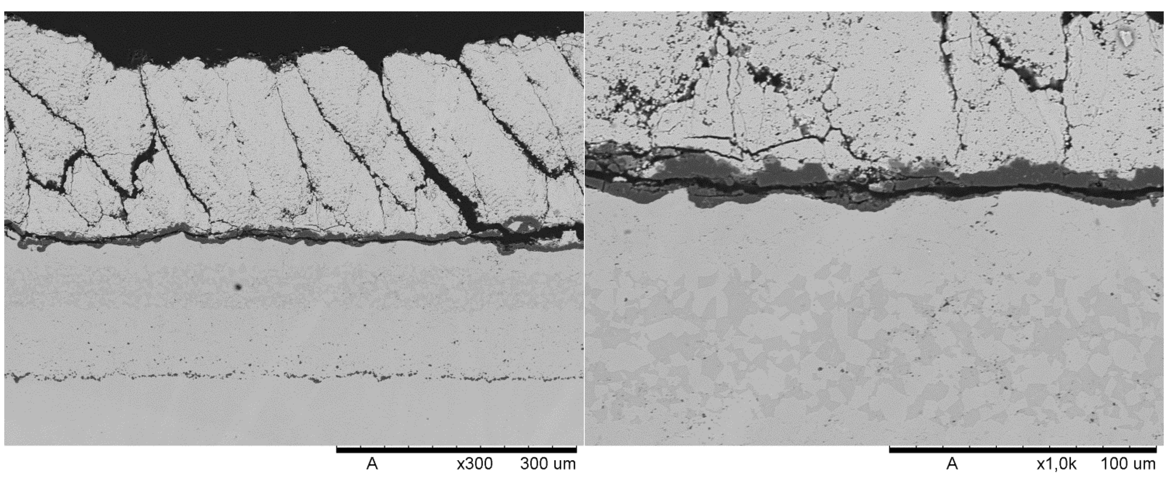
3.5. Failure Microstructures

Samples from TCF testing after failure were removed from the test rig and prepared for microstructural analysis. Samples were mounted in low viscosity epoxy resin before sectioning in order not to induce damage to the coatings from the preparation procedure. Sectioned samples were then remounted and polished using a standard preparation procedure for TBC coatings.
Figure 10. Thermo-cyclic fatigue lifetime results.
Coatings 05 00338 g010
Figure 11 shows coating T3 after approximately 350 thermo-cyclic fatigue cycles. The failure of the sample is typical for all of the T-series samples and is similar to those from the previous research samples on HVAF bond coat [12]. At the ceramic interface with the bond coat there is a fairly uniform thermally grown oxide (TGO) layer that consists primarily of alumina with minimal amounts of mixed oxide phases present. Cracking appears to have initiated within the TGO layer and propagated across the coating interface predominantly within the TGO layer itself. Cracking is driven by stresses built up due to oxide growth and thermal mismatch within the interface region during cyclic exposure. Hille et al. have demonstrated crack generation in similar interfaces at surface asperities within the TGO [25]. The results of modeling the same TGO interface region under repeated thermal cycling have shown crack initiation at surface asperities in the TGO layer repeatedly as the layer itself grows [26]. These can act as the initial nucleation sites for further crack growth across the interface.
Figure 11. Suspension T3, approximately 350 TCF cycles.
Coatings 05 00338 g011
Coating C1 in Figure 12 shows a slightly different failure to that observed in the T-series coatings. Coating failures occurred at approximately 160 cycles. The formation of a uniform TGO layer can be noted in the cross sections. Crack initiation appears to have occurred within the TGO or at the interface with the SPS layer. Unlike the T-series coatings, the cracking propagated through the YSZ coating, leaving an uneven layer of ceramic attached to the TGO beneath. In this case there is a lot of very angular cracking within the ceramic SPS coating at the base of the columns not present in any of the other coatings tested in this study. The modeling results of Hille et al. suggest that cracking will only propagate into the ceramic top coat in systems where fracture toughness of the ceramic coating is relatively low [26]. The results then correlate with the lower fracture toughness of the 14 wt % YSZ relative to standard 8 wt % YSZ and may therefore suggest the cause of early failure.
Figure 12. Suspension C1, approximately 160 TCF cycles.
Coatings 05 00338 g012
A microstructure from a failed C2 TCF sample can be seen in Figure 13. The failure appears to have resulted from cracking through the first interpass porosity band. As shown in the higher magnification image at the right of Figure 13, this cracking left an almost uniform layer of YSZ attached to the TGO. This image also shows evidence that the cracking may have initiated within the TGO or at the TGO-bond coat interface. Similar failures were noted previously for nano-suspension coatings in previous work [12]. The presence of such IPBs may be beneficial for reduction in thermal conductivity of the coating; however, they also act as a low energy pathway for crack propagation.
Figure 13. Coating C2, approximately 150 cycles.
Coatings 05 00338 g013

4. Conclusions

This study has investigated how changes to suspension properties from solids loading, particle size, solvent, and manufacturer affected coatings produced with a fixed set of spray parameters. The resulting coatings showed:
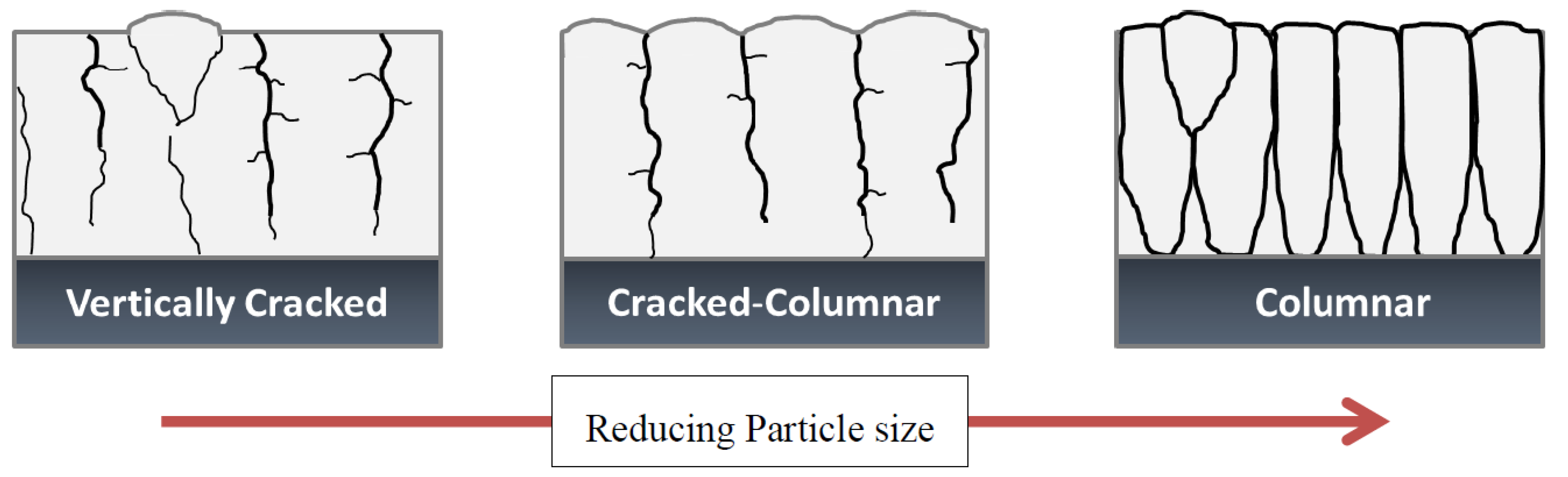
  • For ethanol-based suspensions, the tendency for columnar microstructure formation increases with reducing suspension viscosity due to stronger atomization of the suspension and resultant smaller particles in the plasma plume. Additionally, increasing suspension viscosity increased the coating thermal conductivity and tended to reduce the thermo-cyclic fatigue lifetimes.
  • Changing the suspension solvent from ethanol to water produced a shift in the coating microstructure morphology from columnar to vertically-cracked. Higher suspension surface tension; due to moving from ethanol to water as a solvent, has the tendency to dramatically increase atomized droplet size and therefore transitions deposition to a more APS-like coating. This change also increased the coating thermal conductivity by roughly 3% and decreased the thermo-cyclic fatigue life by 54%.
  • Median powder particle size in suspension has only an indirect impact on the size of the depositing droplets and consequently the coating deposition type. It is clear that the simple metric of powder size in suspension is not sufficient to help define parameters for suspension plasma spray coating.
The results demonstrate significant changes in coating microstructure and performance are possible by suspension property adjustments. However, it should be pointed out that suspension properties are just one critical part of SPS coating production; the plasma, injection, substrate, and part/torch motion parameters will also impact the coating microstructure and the system should be considered as a whole.

Acknowledgments

The authors would like to thank Bob Gelinas and Helmut Ringdorfer for their work setting up the collaboration project. Thanks to Jönköping University for access to the thermal properties laboratory. The first author would also like to thank Nicolaie Markocsan and Per Nylen for their helpful discussions and hands off approach.

Author Contributions

Nicholas Curry co-wrote the article, planned the spray trials and conducted the coating analysis. Kent VanEvery planned and performed the spray trials for SPS layers and co-wrote the article. Johann Susnjar prepared the suspensions and their associated viscosity measurements. Stefan Bjorklund performed the HVAF bond coat preparation for the experimental samples.

Conflicts of Interest

The authors declare no conflict of interest

References

  1. Killinger, A.; Gadow, R.; Mauer, G.; Guignard, A.; Vaßen, R.; Stöver, D. Review of new developments in suspension and solution precursor thermal spray processes. J. Therm. Spray Technol. 2011, 20, 677–695. [Google Scholar] [CrossRef]
  2. Bacciochini, A.; Ilavsky, J.; Montavon, G.; Denoirjean, A.; Ben-ettouil, F.; Valette, S.; Fauchais, P.; Wittmann-teneze, K. Quantification of void network architectures of suspension plasma-sprayed (SPS) yttria-stabilized zirconia (YSZ) coatings using ultra-small-angle X-ray scattering (USAXS). Mater. Sci. Eng. A 2010, 528, 91–102. [Google Scholar] [CrossRef]
  3. Feuerstein, A.; Knapp, J.; Taylor, T.; Ashary, A.; Bolcavage, A.; Hitchman, N. Technical and economical aspects of current thermal barrier coating systems for gas turbine engines by thermal spray and EB-PVD: A review. J. Therm. Spray Technol. 2008, 17, 199–213. [Google Scholar] [CrossRef]
  4. Berghaus, J.O.; Bouaricha, S.; Legoux, J.-G.; Moreau, C.; Chráska, T. Suspension plasma spraying of nano-ceramics using and axial injection torch. In Proceedings of the International Thermal Spray Conference, Basel, Switzerland, 2–4 May 2005.
  5. Fauchais, P.; Vardelle, M.; Goutier, S.; Vardelle, A. Key challenges and opportunities in suspension and solution plasma spraying. Plasma Chem. Plasma Process. 2015, 35, 511–525. [Google Scholar] [CrossRef]
  6. VanEvery, K.; Krane, M.; Trice, R.; Wang, H.; Porter, W.; Besser, M.; Sordelet, D.; Ilavsky, J.; Almer, J. Column formation in suspension plasma-sprayed coatings and resultant thermal properties. J. Therm. Spray Technol. 2011, 20, 817–828. [Google Scholar] [CrossRef]
  7. Fazilleau, J.; Delbos, C.; Rat, V.; Coudert, J.F.; Fauchais, P.; Pateyron, B. Phenomena involved in suspension plasma spraying part 1: Suspension injection and behavior. Plasma Chem. Plasma Process. 2006, 26, 371–391. [Google Scholar] [CrossRef]
  8. Fauchais, P.; Rat, V.; Coudert, J.-F.; Etchart-Salas, R.; Montavon, G. Operating parameters for suspension and solution plasma-spray coatings. Surf. Coat. Technol. 2008, 202, 4309–4317. [Google Scholar] [CrossRef]
  9. Pawlowski, L. Suspension and solution thermal spray coatings. Surf. Coat. Technol. 2009, 203, 2807–2829. [Google Scholar] [CrossRef]
  10. Wolfe, H.E.; Anderson, W.H. Kenetics, Mechanism, and Resultant Droplet Sizes of the Aerodynamic Breakup of Liquid Drops. Aerojet General Corporation Research and Development Department: Downey, CA, USA, 1964. [Google Scholar]
  11. Rampon, R.; Marchand, O.; Filiatre, C.; Bertrand, G. Influence of suspension characteristics on coatings microstructure obtained by suspension plasma spraying. Surf. Coat. Technol. 2008, 202, 4337–4342. [Google Scholar] [CrossRef]
  12. Curry, N.; VanEvery, K.; Snyder, T.; Markocsan, N. Thermal conductivity analysis and lifetime testing of suspension plasma-sprayed thermal barrier coatings. Coatings 2014, 4, 630–650. [Google Scholar] [CrossRef]
  13. Curry, N.; Tang, Z.; Markocsan, N.; Nylén, P. Influence of bond coat surface roughness on the structure of axial suspension plasma spray thermal barrier coatings—Thermal and lifetime performance. Surf. Coat. Technol. 2015, 268, 15–23. [Google Scholar] [CrossRef]
  14. Gong, K.; VanEvery, H.; Wang, R.W. Trice, Microstructure and thermal properties of inflight rare-earth doped thermal barriers prepared by suspension plasma spray. J. Eur. Ceram. Soc. 2014, 34, 1243–53. [Google Scholar] [CrossRef]
  15. Taylor, R.E. Thermal conductivity determinations of thermal barrier coatings. Mater. Sci. Eng. A 1998, 245, 160–167. [Google Scholar] [CrossRef]
  16. Curry, N.; Markocsan, N.; Östergren, L.; Li, X.-H.; Dorfman, M. Evaluation of the lifetime and thermal conductivity of dysprosia-stabilized thermal barrier coating systems. J. Therm. Spray Technol. 2013, 22, 864–872. [Google Scholar] [CrossRef]
  17. Curry, N.; Donoghue, J. Evolution of thermal conductivity of dysprosia stabilised thermal barrier coating systems during heat treatment. Surf. Coat. Technol. 2012, 209, 38–43. [Google Scholar] [CrossRef]
  18. ISO 10545-3:1995 Ceramic Tiles Part 3: Determination of Water Absorption, Apparent Porosity, Apparent Relative Density and Bulk Density; International Organization for Standardization: Geneva, Switzerland, 2010.
  19. Pateyron, B.; Calve, N.; Pawlowski, L. Influence of water and ethanol on transport properties of the jets used in suspension plasma spraying. Surf. Coat. Technol. 2013, 220, 257–260. [Google Scholar] [CrossRef]
  20. Nicholls, J.R.; Lawson, K.J.; Johnstone, A.; Rickerby, D.S. Methods to reduce the thermal conductivity of EB-PVD TBCs. Surf. Coat. Technol. 2002, 151–152, 383–391. [Google Scholar] [CrossRef]
  21. Schelling, P.K.; Phillpot, S.R. Mechanism of thermal transport in zirconia and yttria-stabilized zirconia by molecular-dynamics simulation. J. Am. Ceram. Soc. 2001, 84, 2997–3007. [Google Scholar] [CrossRef]
  22. Klemens, P.G. Theory of Thermal Conduction in Thin Ceramic Films. Int. J. Thermophys. 2001, 22, 265–275. [Google Scholar] [CrossRef]
  23. Bjorneklett, A.; Haukeland, L.; Wigren, J.; Kristiansen, H. Effective medium theory and the thermal conductivity of plasma-sprayed ceramic coatings. J. Mater. Sci. 1994, 29, 4043–4050. [Google Scholar] [CrossRef]
  24. Curry, N.; Markocsan, N.; Li, X.-H.; Tricoire, A.; Dorfman, M. Next generation thermal barrier coatings for the gas turbine industry. J. Therm. Spray Technol. 2010, 20, 108–115. [Google Scholar] [CrossRef]
  25. Hille, T.S.; Nijdam, T.J.; Suiker, A.S.J.; Turteltaub, S.; Sloof, W.G. Damage growth triggered by interface irregularities in thermal Barrier Coatings. Acta Mater. 2009, 57, 2624–2630. [Google Scholar] [CrossRef]
  26. Hille, T.S.; Turteltaub, S.; Suiker, A.S.J. Oxide growth and damage evolution in thermal barrier coatings. Eng. Fract. Mech. 2011, 78, 2139–2152. [Google Scholar] [CrossRef]

