Article

Machining Performance of Sputter-Deposited (Al0.34Cr0.22Nb0.11Si0.11Ti0.22)50N50 High-Entropy Nitride Coatings

1
Department of Materials Science and Engineering, National Tsing Hua University, Hsinchu 30013, Taiwan
2
Department of Materials Science and Engineering, National Chung Hsing University, Taichung 40227, Taiwan
*
Author to whom correspondence should be addressed.
Coatings 2015, 5(3), 312-325; https://doi.org/10.3390/coatings5030312
Submission received: 16 May 2015 / Revised: 30 June 2015 / Accepted: 14 July 2015 / Published: 23 July 2015
(This article belongs to the Special Issue High Entropy Alloy Coatings)

Abstract

:
(Al0.34Cr0.22Nb0.11Si0.11Ti0.22)50N50 high-entropy nitride coatings prepared by reactive magnetron sputtering have been proved to have high hardness and superior oxidation resistance. Their thermal stability, adhesion strength, and cutting performance were investigated in this study. Hardness of the coating is 36 GPa, which only decreases slightly to 33 GPa after 900 °C annealing either in air or in vacuum for 2 h. No significant change in phase and microstructure were detected after annealing at 1000 °C. Rockwell C indentation and scratch tests shows that Ti interlayer provides a good adhesion between the nitride film and WC/Co substrates. In various milling tests, inserts coated with (Al0.34Cr0.22Nb0.11Si0.11Ti0.22)50N50 have evidently smaller flank wear depth than commercial inserts coated with TiN and TiAlN, even with their smaller thickness. Therefore, the (Al0.34Cr0.22Nb0.11Si0.11Ti0.22)50N50 coating has great potential in hard coating applications.

1. Introduction

Conventionally, high speed machining is usually performed with cutting fluids. Cutting fluids not only serve as lubricants but also dissipate massive heat generated in high speed machining. However, cutting fluids are not environmental friendly and meanwhile raise the cost of machining. Thus, dry machining are gradually being adopted in industry [1,2,3,4].
Some research indicates that carbide inserts survive longer in dry machining; still the heat generated during high speed machining will cause oxidation and coarsening and thus deteriorates the quality of inserts. The application of hard coatings, either by physical or chemical vapor deposition (PVD or CVD), is a common solution to prolong tool life [5,6].
Nitride coatings deposited using PVD techniques, such as TiN, TiCN, or TiAlN, are of special interest for their impressive performance and relatively lower costs. TiN is the most studied and used coating system for its high hardness, low coefficient of friction, and good adhesion to the substrates. However, its rapid oxidation starting at 550 °C limits the application in high speed machining [7,8]. TiCN coatings are known for their self-lubricating property and the particular low coefficient of friction [9,10,11,12]. However, their insufficient thermal stability and oxidation resistance make them inadequate for high temperature use. TiAlN is also a widely applied system. The addition of Al increases coating hardness significantly [8,13]. Moreover, the formation of dense Al2O3 layer at high temperature effectively prevents the inward diffusion of oxygen, and also enhances the hot hardness and chemical stability of coatings [14,15]. Higher cutting speed, better machining quality, and longer tool life are thus accomplished by the usage of TiAlN coatings [13,16]. However, severe oxidation of TiAlN still takes place when temperature is higher than 800 °C [7,17]. Extended systems based on these coatings are thus developed and studied successively to meet the demands for higher temperature applications.
A new category of nitride coatings based on high-entropy alloys (HEAs) [18], i.e., high-entropy nitrides (HENs), has been studied in recent years. These HEN coatings, with five or more principal target elements, are reported to possess many attractive properties. For example, the hardness of (AlCrTaTiZr)100−xNx [19,20], (AlCrSiTiV)100−xNx [21], (AlCrMoSiTi)100−xNx [22], and (AlMoNbSiTaTiVZr)100−xNx [23], (TiVCrZrHf)100−xNx [24], and (TiZrNbHfTa)100−xNx [25] all fall in the range of 32–36 GPa when the value of x is about 50. The hardness of (AlCrNbSiTiV)N is even higher (42 GPa), and still remains in the superhard level after vacuum annealing at 1000 °C for 5 h [26,27]. Some HENs not only have high hardness, but also exhibit excellent oxidation resistance. For example, non-equimolar (Al0.34Cr0.22Nb0.11Si0.11Ti0.22)50N50 coatings has a hardness of 36 GPa, and the thickness of surface oxide after air annealing at 900 °C for 50 h is only 290 nm [28,29]. Nice thermal stability of (AlCrTaTiZr)Nx has been reported by Chang et al. [30] and Lai et al. [19] reported pleasing anti-wear performances demonstrated in (AlCrTaTiZr)100−xNx. These properties make HENs very promising in tool protection. However, no results of practical cutting tests are reported so far.
In this study, the thermal stability and machining properties of (Al0.34Cr0.22Nb0.11Si0.11Ti0.22)50N50 coatings are investigated in consideration of its excellent oxidation resistance and high hardness mentioned above. Firstly, X-ray diffraction (XRD) and nanoindentation are used to study the crystallographic structure and hardness of annealed coatings. Furthermore, various interlayers are applied to enhance coatings’ adhesion to the WC/Co substrates. Lastly, the machining properties of the HEN coated inserts are tested by face milling of 304 stainless steel and SKD11 steel. The performance of commercial TiN and TiAlN coated inserts are also evaluated for comparison.

2. Materials and Methods

2.1. Target and Film Preparation

The procedure of target preparation has been described in previous literature. The (Al0.34Cr0.22Nb0.11Si0.11Ti0.22)50N50 coatings were deposited on oxidized (100) silicon wafer which has a 200 nm-thick SiO2 layer on surface, WC/Co substrates (2 cm × 2 cm), and cemented carbide inserts (Hitachi TPMN160308 EX35). The deposition was conducted in a direct current (DC) magnetron sputtering system with a background pressure below 1.33 × 10⁻³ Pa (1 × 10⁻⁵ Torr.) from Al0.34Cr0.22Nb0.11Si0.11Ti0.22 alloy target. Reactive sputtering was performed at a fixed working pressure of 0.667 Pa (5 mTorr) in an Ar/N2 gas mixture. The gas flow rate is 20 sccm for both Ar and N2. Film was grown to a thickness about 1.4 μm. Interlayers were deposited onto WC/Co substrates from Cr, Ti, and Al0.34Cr0.22Nb0.11Si0.11Ti0.22 targets before depositing nitride coatings. The interlayers were deposited in pure Ar atmosphere at a flow rate of 40 sccm at working pressure of 0.667 Pa. The thickness is controlled at about 100 nm. Substrate temperature and sputtering power was maintained at 415 °C and 150 W, respectively, throughout the deposition. The working distance was about 11 cm. Both of the alloy target and the substrates are pre-sputtered before the deposition to avoid contamination.

2.2. Film Characterization

The chemical composition of these (Al, Cr, Nb, Si, Ti)N coatings was analyzed using a field-emission electron probe micro-analyzer (FE-EPMA, JXA-8500F, JEOL, Tokyo, Japan). The coating is a stoichiometric nitride, and the composition of the target elements is close to the designed ratio. The formula of this HEN can thus be denoted as (Al0.34Cr0.22Nb0.11Si0.11Ti0.22)50N50. The vacuum annealing of samples was performed in a rapid thermal annealing furnace with a background pressure lower than 1.33 × 10⁻⁴ Pa (1 × 10⁻⁶ Torr.). The temperature was raised at ramping rate of 200 °C/min to targeting temperature. After holding for 2 h, the sample was furnace-cooled to room temperature. Air annealing was conducted in an air furnace at various temperatures for 2 h with ramping rate of 15 °C/min. The crystallographic structures of coatings were characterized using a glancing angle X-ray diffractrometer (GIXRD, MXP18, MAC Science, Japan) with Cu Kα radiation operated at 40 kV and 150 mA. The scanning speed was 4 °/min and the incident angle was 1°. The hardness values of films deposited on (100) Si wafers were measured with a Micromaterials Nano Test indentation system using a Berkovich indenter and a continuous applied load of 5 mN. The roughness of the HEN films examined by AFM (atomic force microscope, NS3a-controller with D3100 stage, Digital Instrument, USA) is lower than 0.5 nm. The indentation depth was controlled to be less than 1/10 of the film thickness to avoid substrate effect. The hardness was calculated from the loading/uploading curves of indentation tests following the analysis method proposed by Oliver and Pharr [31]. Ten points were measured for each sample to obtain a reliable result. A field-emission scanning electron microscope (FESEM, JSM-6500F, Tokyo, Japan) operated at 15 kV was used to observe surface and cross-sectional microstructures of films.

2.3. Adhesion Test

The adhesion of films was examined by both Rockwell C indentation and scratch test. In Rockwell C indentation test, a 120° cone-shaped diamond tip was applied perpendicularly to the film surface with a load of 1470 N (150 kgf). The morphology of indentation area was observed using an optical microscope (OM, Pentad Scientific Corporation, Hsinchu, Taiwan), and then classified into six ratings evaluating the damage degree from HF1 to HF6 [32]. In this classification, HF1 indicates the least cracks near the indentation boundaries and implies a good bonding of films to the substrates. HF6 represents severe delamination of the coatings, and indicates a poor adhesion of films. Adhesions rated from HF1 to HF4 are adequate in commercial demands. The scratch test was performed using a progressive load scratch tester (Sense Ted, Ltd., Kaohsiung, Taiwan) equipped with a spherical Rockwell diamond indenter (200 μm in radius). The indenter was slid over coatings surface and the load was increased from 0 to 100 N. The loading rate was 100 N/min, while the sliding speed is 10 mm/min. Five scratches were made for each sample to get a trusted result. The critical load corresponding to adhesive failure on the scratch track was evaluated by OM observation. Stallard et al. [33] identified four kinds of film failure events and labeled as critical loads from LC1 to LC4. LC1 and LC2 belong to the cohesive failure mode, which is more related to the coating's intrinsic properties. LC3 denotes the load at which the initial adhesive failure occurs, while LC4 indicates the total failure of coating that the substrate has been exposed to completely. Thus, LC3 and LC4 provide a better index for evaluating the adhesion quality of coatings. In practical use, the critical loads LC3 and LC4 should be higher than 60 N to meet the industrial demands.

2.4. Milling Test

The machining properties of TiN, TiAlN, and HEN coated inserts were evaluated by dry face milling of SKD11 steel and 304 stainless steel. The hardness of SKD11 steel is 260 Hv, while that of 304 Stainless steel is 190 Hv. Tests on 304 stainless steel were performed at two cutting speeds: 76 and 160 m/min. Feed rate was 0.22 mm/rev. Depth of cut was controlled at 0.2 mm for the lower cutting speed and 0.1 mm for the higher one to avoid severe vibration of the milling machine. For SKD11 steel, the cutting speed was 76 mm/min. Depth of cut was 0.1 mm, and the feed rate was 0.22 mm/rev. Each milling was interrupted every 180 m of cutting distance and the morphology of the rake face was observed using SEM so that the flank wear can be measured. For comparison, a continuous milling test of 304 stainless steel at higher cutting speed, 160 m/min, was also undertaken to imitate the practical use of inserts and evaluate the continuous protection ability of different coatings at higher cutting temperature.

3. Results and Discussion

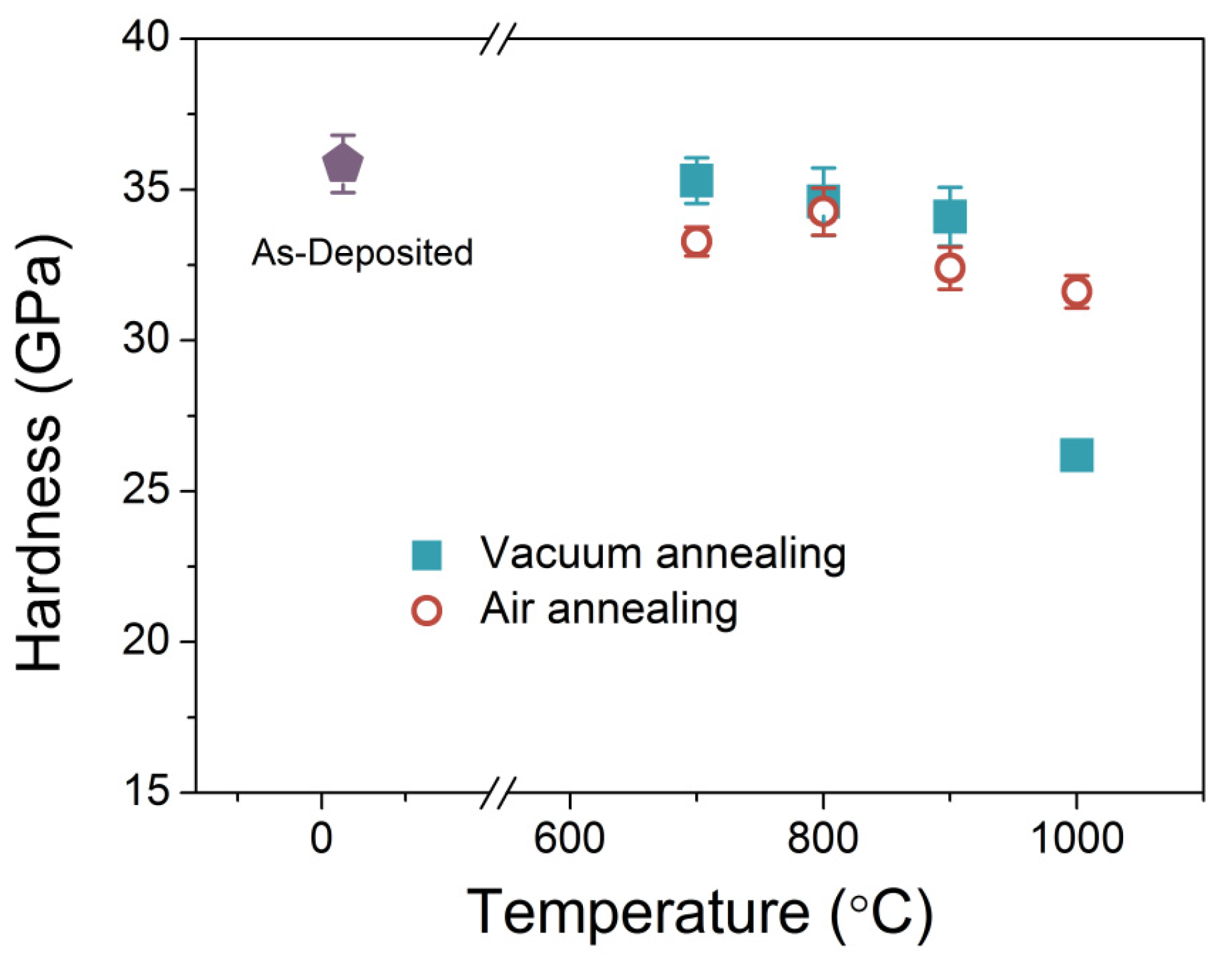
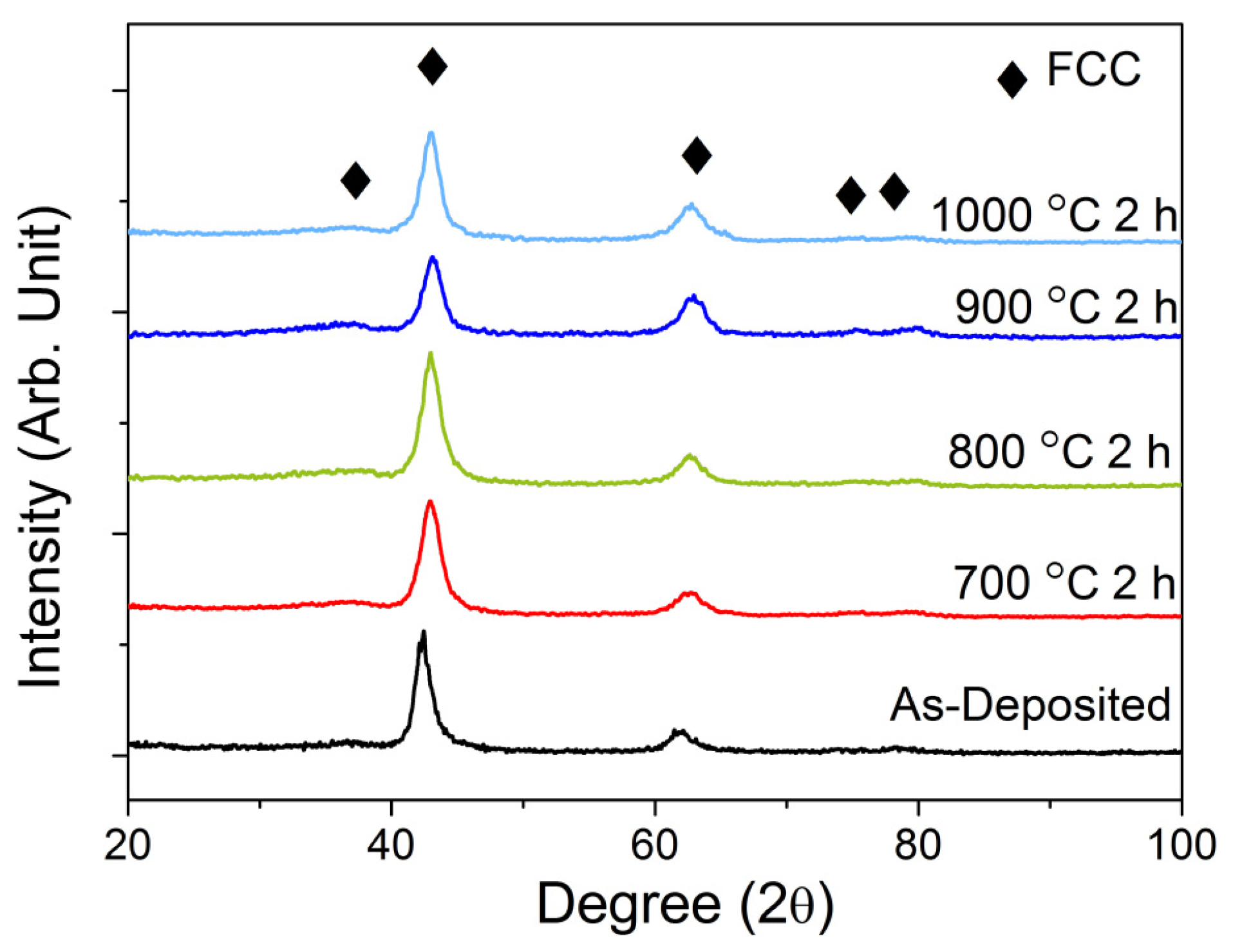
3.1. Thermal Stability and Film Hardness

The high hardness and outstanding oxidation resistance of (Al0.34Cr0.22Nb0.11Si0.11Ti0.22)50N50 have already been reported previously [29]. In practical machining operations, however, the coatings will be heated to temperatures as high as 1000 °C during machining, and then cooled to room temperature. Therefore, the stability of the structure and properties of the coatings after these excessive heating is critical and shall be tested. Figure 1 shows the XRD patterns of the coating after vacuum annealing at different temperatures. All coatings retain their NaCl-type FCC structure. Additionally, no significant grain growth is observed—even for samples annealed at 1000 °C. The suppression of grain coarsening in high-entropy nitride at high temperature has been reported by Huang et al. [26]. The reason for the stability of phase and structure at high temperature is twofold. Firstly, the stability of solid solution phase at high temperature is the major reflection of high-entropy effect. Secondly, severe lattice distortion effect reduces grain boundary energy and thus lowers the driving force of grain coarsening [26]. It is also noted that a small shift of peaks indicating the decrease of lattice constant is found as annealing temperature increases. This reduction is attributed to the elimination of point defects introduced during sputtering deposition.
Figure 1. XRD patterns of as-deposited and vacuum-annealed (Al0.34Cr0.22Nb0.11Si0.11Ti0.22)50N50 coatings.
Coatings 05 00312 g001
The hardness of coatings after air or vacuum annealing is shown in Figure 2. As-deposited coatings have a hardness of 36 GPa. The high hardness of the as-deposited (Al0.34Cr0.22Nb0.11Si0.11Ti0.22)50N50 coatings was reported to be a combined result of nano-sized grains, dense structures, and residual stress [28]. Annealing at 700, 800, and 900 °C in vacuum slightly softens the coatings, but the hardness values still remain higher than 33 GPa. As long as the change in structure due to annealing is insignificant (700–900 °C), the strengthening effect is still retained. In addition, the excellent capability of high-entropy nitrides to retain the original structure at high temperatures is also reported by Huang, Lai, and Chang [26,34,35]. Annealing at 1000 °C decreases the film hardness value to 26 GPa, but this value is still higher than that of commercial TiN coatings [36]. This decrease of hardness might be due to the loss of nitrogen in vacuum. On the other hand, all coatings annealed in air have hardness values between 31 and 33 GPa, which means no significant change in hardness takes place. It was reported that a thin, multi-layer oxide scale forms on the surface of the (Al0.34Cr0.22Nb0.11Si0.11Ti0.22)50N50 coatings after annealing. This dense oxide scale acts as a diffusion barrier so that the inner nitride is not further oxidized [29]. The outward diffusion of nitrogen is also inhibited due to the oxide scale. Therefore, the hardness is preserved.
The above demonstrates that both the structure and hardness of the (Al0.34Cr0.22Nb0.11Si0.11Ti0.22)50N50 coatings are not greatly affected after heat treatment. Such outstanding stability guarantees the quality of the coatings in practical machining operations.
Figure 2. Hardness values of as-deposited and air/vacuum-annealed (Al0.34Cr0.22Nb0.11Si0.11Ti0.22)50N50 coatings.
Coatings 05 00312 g002

3.2. Adhesion Test

The adhesion of the coating to WC/Co substrates was studied by two most common adhesion tests, Rockwell C indentation test and progressive load scratch test. To optimize the adhesion of (Al0.34Cr0.22Nb0.11Si0.11Ti0.22)50N50 on WC/Co substrates, three different interlayers—Cr, Ti, and Al0.34Cr0.22Nb0.11Si0.11Ti0.22—were applied on the substrates before the deposition of HEN coating.
The evaluation of adhesion strength by Rockwell C indentation tests is based on the damages of the coatings adjacent to the indentation boundary, and six levels of adhesion, HF1 to HF6, have been proposed previously [32]. HF1 to HF4 indicate adequate adhesion, and no evident spallation is seen around the boundary. In contrast, for HF5 and HF6, severe delamination has taken place, which reflects inadequate adhesion between film and substrate. Based on the images of films after Rockwell C tests (Figure 3), Cr interlayer is incapable of providing some adhesion (HF5), while Ti and Al0.34Cr0.22Nb0.11Si0.11Ti0.22 interlayers provide better adhesion strength (HF4). Also, the degree of cracking represents the toughness of coatings to some extent. Cracks found at the boundary of indentations illustrate a medium toughness of (Al0.34Cr0.22Nb0.11Si0.11Ti0.22)50N50 coating itself.
Figure 3. The OM images of Rockwell C indentation of (Al0.34Cr0.22Nb0.11Si0.11Ti0.22)50N50 coatings on WC/Co substrates with various interlayer: (a) Cr interlayer, (b) Al0.34Cr0.22Nb0.11Si0.11Ti0.22 interlayer, and (c) Ti interlayer.
Coatings 05 00312 g003
The morphology of tracks after scratch tests is presented in Figure 4. It is seen that the adhesion strength of Cr interlayer is poor. Its LC3 is only 3 N, and the LC4 is only 14 N. These values are apparently lower than that of the commercial criterion (≥60 N). HEN coatings using Al0.34Cr0.22Nb0.11Si0.11Ti0.22 as interlayer exhibit higher critical load. The LC3 and LC4 are 47 and 55 N, respectively, but the values are still lower than 60 N. Ti interlayer provides the best adhesion among all interlayers, with both LC3 and LC4 values higher than 100 N (no delamination/cracks along the track is observed). The adhesion strengths based on scratch tests are consistent with that based on Rockwell-C indentation tests. These results are summarized in Table 1.
Figure 4. The OM images of the scratch track of (Al0.34Cr0.22Nb0.11Si0.11Ti0.22)50N50 coatings on WC/Co substrates with various interlayer: (a) Cr interlayer, (b) Al0.34Cr0.22Nb0.11Si0.11Ti0.22 interlayer, and (c) Ti interlayer.
Coatings 05 00312 g004
Table 1. Critical loads in scratch test and damage ratings in Rockwell C indentation of (Al0.34Cr0.22Nb0.11Si0.11Ti0.22)50N50 coatings with various interlayers.
InterlayerLC3LC4Rockwell C (150 kg)
Cr2 ± 0.2 N14 ± 4 NHF5
Al0.34Cr0.22Nb0.11Si0.11Ti0.2247 ± 4 N55 ± 2.9 NHF4
Ti>100 N>100 NHF4

3.3. Milling Test

In order to study the cutting performance of (Al0.34Cr0.22Nb0.11Si0.11Ti0.22)50N50 coatings, dry machining of 304 stainless steel and SKD11 steel is performed. The HEN coatings are deposited onto commercial cemented carbide inserts with 100 nm thick Ti interlayer. The cross-sectional and surface structures of the coatings on inserts are demonstrated in Figure 5a,b, respectively. The thickness of HEN coatings was measured from the SEM image and is about 1.4 μm. Its cross-sectional image shows a dense and fine fiber structure, while the surface consists of clusters of grains. For comparison, commercial TiN and TiAlN coated cemented carbide inserts are also tested. The measured hardness is 20 and 30 GPa for TiN and TiAlN coatings, respectively. The surface morphologies of these films are presented in Figure 5c,d, which reveal the typical surface structure of coatings deposited by the anodic vacuum arc process. XRD patterns of uncoated and coated inserts are shown in Figure 6. The uncoated insert exhibits peaks belonging to WC and Co. All three coatings have a simple B1 structure. Insert coated with (Al0.34Cr0.22Nb0.11Si0.11Ti0.22)50N50 shows peaks of WC, indicating that the HEN film is thinner than TiN and TiAlN films. It is also noted that the relative intensities of peaks near 37° and 42° of HEN coatings are different in Figure 1 and Figure 6. This suggests that the orientation of film is influenced by substrate material since the substrate used for the films in Figure 1 was (100) Si with amorphous native-oxide surface layer SiO2 whereas that used for the films in Figure 6 is crystalline WC/Co composite. Although the morphology and orientation of nuclei on the substrate surface could be related with the surface roughness, crystallinity and chemical composition, further investigation is needed in the future in order to provide a detailed explanation.
Figure 5. SEM micrographs of (a) cross-sectional and (b) surface structures of (Al0.34Cr0.22Nb0.11Si0.11Ti0.22)50N50 coatings; (c) surface structures of TiN coatings; and (d) surface structures of TiAlN coatings.
Coatings 05 00312 g005
Figure 6. XRD patterns of uncoated, TiN, TiAlN, and (Al0.34Cr0.22Nb0.11Si0.11Ti0.22)50N50 coated inserts.
Coatings 05 00312 g006
In machining tests, flank wear depth is a common index for tool life assessment. Lower flank wear depth indicates better wear resistance, and thus represents longer tool life. The maximum flank wear of insert edge is measured every 180 m of cutting distance, and the results for milling SKD11 steel are shown in Figure 7. In the initial stage (first 180 m of cutting distance) of the interrupted milling test, the HEN coating already demonstrates its advantage over TiN and TiAlN by its smallest flank wear depth of 90 μm. It should be mentioned that the thickness of HEN is smaller than that of TiN and TiAlN, which means HEN will further expand the lead over commercial counterparts if all coatings have the same thickness. The HEN coating keeps its lead throughout the milling test. After a total cutting distance of 900 m, the wear depth of uncoated, TiN-, TiAlN-, and HEN-coated inserts are 227, 200, 188, and 176 μm, respectively. As shown in Figure 8, the wear lands of all inserts have similar appearance, and a small amount of debris is also found. The white region represents the exposed WC/Co substrate. Gray region represents the gradient wear of the film. The dark region is the un-worn film.
Figure 7. Maximum flank wear depths of uncoated, TiN, TiAlN, and (Al0.34Cr0.22Nb0.11Si0.11Ti0.22)50N50 coated inserts milling against SKD11 steel as a function of cutting distance in the interrupted milling test.
Coatings 05 00312 g007
Figure 8. Flank wear patterns of cutting inserts coated with (a) TiN, (b) TiAlN, and (c) (Al0.34Cr0.22Nb0.11Si0.11Ti0.22)50N50 after interrupted milling tests against SKD11 steel with the cutting distance of 900 m.
Coatings 05 00312 g008
Figure 9 demonstrates the interrupted milling results against 304 stainless steel (HV 190). At the smallest cutting distance (180 m), the three coated inserts have similar flank wears. However, for longer cutting distances, HEN-coated inserts has the smallest wear depth. After 900 m of cutting, the wear depth of uncoated, TiN-, TiAlN-, and HEN-coated inserts are 226, 202, 184, and 175 μm, respectively. HEN coatings again show advantage over the two commercial counterparts. The morphology of the wear land against 304 stainless steel is shown in Figure 10. The feature is quite different from that seen in Figure 10. This is because 304 stainless steel is tougher than SKD 11 workpiece used for Figure 8, and cutting depth is double that used for Figure 8. That means the present cutting condition is severer than that for Figure 8. The cutting edge has some worn-out regions and the wear land shows the exposed WC/Co substrate (grain-like and white). Some stainless steel layers (thick layer is gray and thin layer is white) adhere to the worn-out edge, exposed WC/Co substrate and even un-worn film. It is noted that HEN-coated insert also displays a smaller worn-out cutting edge than the other two indicating better protection.
Figure 9. Maximum flank wear depths of uncoated, TiN, TiAlN, and (Al0.34Cr0.22Nb0.11Si0.11Ti0.22)50N50 coated inserts milling against 304 stainless steel as a function of cutting distance in the interrupted milling test.
Coatings 05 00312 g009
Figure 10. Flank wear patterns of cutting inserts coated with (a) TiN, (b) TiAlN, and (c) (Al0.34Cr0.22Nb0.11Si0.11Ti0.22)50N50 after interrupted milling tests against 304 stainless steel with the cutting distance of 900 m.
Coatings 05 00312 g010
A more rigorous machining condition, i.e., continuous machining at higher cutting speed (160 m/min), is executed. The inserts were observed using SEM until the cutting distance had reached 900 m. The difference in wear resistance between HEN-coated inserts and commercial inserts at this condition is evidently larger—The wear depth of HEN-coated inserts is 23% and 25% smaller than that of TiN-coated and TiAlN-coated inserts, respectively, as shown in Figure 11. It is emphasized again here that the thickness of the HEN coating is the smallest among the three. If the thicknesses of the three coatings are equal, HEN should further outperform the commercial counterparts.
Figure 11. The comparison of maximum flank wear among TiN-, TiAlN-, and HEN-coated inserts after continuous milling tests against 304 stainless steel for a cutting distance of 900 m.
Coatings 05 00312 g011
In such rigorous cutting conditions, the local temperature at the workpiece-tool contact point can be very high. This can significantly deteriorate the performance of the coatings due to two reasons. Firstly, the coating itself can soften and therefore lose its wear resistance. This is not only due to the intrinsic thermal softening of the material, but can also be a result of structural coarsening at high temperatures. Secondly, oxidation takes place at high temperature, which turns the nitride coatings to oxides with worse properties. Therefore, high structural stability and good oxidation resistance are critical to high speed cutting. We have already shown in Section 2.1 that the present HEN has remarkable stability. Annealing the HEN coating at 1000 °C for 2 h in air does not soften the coating significantly (36 GPa to 31 GPa). Note that this annealing temperature is very high and the annealing period is longer than the typical lifetime of tools. This suggests that under practical cutting conditions, the degree of softening should be smaller. For comparison, the hot hardness of TiN coating is reported to decrease from about 22.5 GPa at room temperature to 5.9 GPa at 1000 °C, and that of TiAlN decreases from about 25.0 to 11.8 GPa [13]. As for oxidation resistance, our previous research has already shown that the (Al0.34Cr0.22Nb0.11Si0.11Ti0.22)50N50 HEN possesses excellent quality in this regard. Note that annealing this HEN at 900 °C for 50 h only leads to an oxide layer 330 nm in thickness [29]. In contrast, TiN severely oxidizes at above 550 °C, while TiAlN starts rapid oxidation at above 800 °C [7,15]. The two advantages together lead to better cutting performances, particularly under harsh cutting conditions.

4. Conclusion

The thermal stability, adhesion strength and milling performance of the (Al0.34Cr0.22Nb0.11Si0.11Ti0.22)50N50 high-entropy nitride coating were studied. The HEN possesses good thermal stability. No significant change is seen in XRD patterns. The hardness also remains high—31 GPa after annealing at 900 °C for 2 h in air. Scratch tests show that among Ti, Cr, and Al0.34Cr0.22Nb0.11Si0.11Ti0.22, Ti interlayer leads to the best adhesion strength, with both LC3 and LC4 values higher than 100 N. Inserts with HEN coatings and Ti interlayer show remarkable milling performances as compared to commercial TiN- and TiAlN-coated inserts. In milling tests both against SKD11 steel and 304 stainless steel, HEN-coated inserts have lower flank wear, even when HEN coating is thinner than TiN and TiAlN coatings. The cutting performance of HEN coating is even better as milling is operated continuously at higher speed. The advantage of the (Al0.34Cr0.22Nb0.11Si0.11Ti0.22)50N50 coating over TiN and TiAlN is a combined result of high hardness, good thermal stability and outstanding oxidation resistance. The (Al0.34Cr0.22Nb0.11Si0.11Ti0.22)50N50 coating with Ti interlayer hence shows great potential in protective coating applications.

Acknowledgement

The authors gratefully acknowledge the financial support for this research from the National Science Council of Taiwan under grants NSC 100-2221-E-007-049-MY2.

Author Contributions

Experimental measurements, analysis and interpretation of the results as well as conclusions were conducted by Wan-Jui Shen. The manuscript and artworks were prepared by Wan-Jui Shen and Ming-Hung Tsai, the whole paper was revised by Jien-Wei Yeh with approval by the other co-authors.

Conflicts of Interest

The authors declare no conflict of interest.

References

  1. Derflinger, V.; Brandle, H.; Zimmermann, H. New hard/lubricant coating for dry machining. Surf. Coat. Technol. 1999, 113, 286–292. [Google Scholar] [CrossRef]
  2. Veprek, S.; Veprek-Heijman, M.J.G. Industrial applications of superhard nanocomposite coatings. Surf. Coat. Technol. 2008, 202, 5063–5073. [Google Scholar] [CrossRef]
  3. Mayrhofer, P.H.; Mitterer, C.; Hultman, L.; Clemens, H. Microstructural design of hard coatings. Prog. Mater. Sci. 2006, 51, 1032–1114. [Google Scholar] [CrossRef]
  4. Kathrein, M.; Michotte, C.; Penoy, M.; Polcik, P.; Mitterer, C. Multifunctional multi-component PVD coatings for cutting tools. Surf. Coat. Technol. 2005, 200, 1867–1871. [Google Scholar] [CrossRef]
  5. Knotek, O.; Löffler, F.; Krämer, G. Applications to cutting tools. In Handbook of Hard Coatings; Bunshah, R.F., Ed.; Noyes Publications: New York, NY, USA, 2001; pp. 370–410. [Google Scholar]
  6. Knotek, O.; Lugscheider, E.; Loffler, F.; Kramer, G.; Zimmermann, H. Abrasive wear-resistance and cutting performance of complex PVD coatings. Surf. Coat. Technol. 1994, 68, 489–493. [Google Scholar] [CrossRef]
  7. Wittmer, M.; Noser, J.; Melchior, H. Oxidation-kinetics of tin thin-films. J. Appl. Phys. 1981, 52, 6659–6664. [Google Scholar] [CrossRef]
  8. Zhou, M.; Makino, Y.; Nose, M.; Nogi, K. Phase transition and properties of Ti-Al-N thin films prepared by RF-plasma assisted magnetron sputtering. Thin Solid Films 1999, 339, 203–208. [Google Scholar] [CrossRef]
  9. Vancoille, E.; Celis, J.P.; Roos, J.R. Dry sliding wear of tin based ternary PVD coatings. Wear 1993, 165, 41–49. [Google Scholar] [CrossRef]
  10. Polcar, T.; Novak, R.; Siroky, P. The tribological characteristics of TiCN coating at elevated temperatures. Wear 2006, 260, 40–49. [Google Scholar] [CrossRef]
  11. Knotek, O.; Loffler, F.; Kramer, G. Acr deposition of Ti-C and Ti-C-N using acetylene as a reactive gas. Vacuum 1992, 43, 645–648. [Google Scholar] [CrossRef]
  12. Erturk, E.; Knotek, O.; Burgmer, W.; Prengel, H.G.; Heuvel, H.J.; Dederichs, H.G.; Stossel, C. Ti(C,N) coatings using the arc process. Surf. Coat. Technol. 1991, 46, 39–46. [Google Scholar] [CrossRef]
  13. PalDey, S.; Deevi, S.C. Single layer and multilayer wear resistant coatings of (Ti,Al)N: A review. Mater. Sci. Eng. A 2003, 342, 58–79. [Google Scholar] [CrossRef]
  14. Kawate, M.; Hashimoto, A.K.; Suzuki, T. Oxidation resistance of Cr1−xAlxN and Ti1−xAlxN films. Surf. Coat. Technol. 2003, 165, 163–167. [Google Scholar] [CrossRef]
  15. McIntyre, D.; Greene, J.E.; Hakansson, G.; Sundgren, J.E.; Münz, W.D. Oxidation of metastable single-phase polycrystalline Ti0.5Al0.5N films: Kinetics and mechanisms. J. Appl. Phys. 1990, 67, 1542–1553. [Google Scholar] [CrossRef]
  16. Jindal, P.C.; Santhanam, A.T.; Schleinkofer, U.; Shuster, A.F. Performance of PVD TiN, TiCN, and TiAlN coated cemented carbide tools in turning. Int. J. Refract. Met. Hard Mater 1999, 17, 163–170. [Google Scholar] [CrossRef]
  17. Munz, W.D. Titanium aluminum nitride films—A new alternative to TiN coatings. J. Vac. Sci. Technol. A 1986, 4, 2717–2725. [Google Scholar] [CrossRef]
  18. Tsai, M.H.; Yeh, J.W. High-entropy alloys: A critical review. Mater. Res. Lett. 2014, 2, 107–123. [Google Scholar] [CrossRef]
  19. Lai, C.H.; Cheng, K.H.; Lin, S.J.; Yeh, J.W. Mechanical and tribological properties of multi-element (AlCrTaTiZr)N coatings. Surf. Coat. Technol. 2008, 202, 3732–3738. [Google Scholar] [CrossRef]
  20. Lai, C.H.; Lin, S.J.; Yeh, J.W.; Davison, A. Effect of substrate bias on the structure and properties of multi-element (AlCrTaTiZr)N coatings. J. Phys. D Appl. Phys. 2006, 39, 4628–4633. [Google Scholar] [CrossRef]
  21. Lin, C.H.; Duh, J.G.; Yeh, J.W. Multi-component nitride coatings derived from Ti-Al-Cr-Si-V target in rf magnetron sputter. Surf. Coat. Technol. 2007, 201, 6304–6308. [Google Scholar] [CrossRef]
  22. Chang, H.W.; Huang, P.K.; Yeh, J.W.; Davison, A.; Tsau, C.H.; Yang, C.C. Influence of substrate bias, deposition temperature and post-deposition annealing on the structure and properties of multi-principal-component (AlCrMoSiTi)N coatings. Surf. Coat. Technol. 2008, 202, 3360–3366. [Google Scholar] [CrossRef]
  23. Tsai, M.H.; Lai, C.H.; Yeh, J.W.; Gan, J.Y. Effects of nitrogen flow ratio on the structure and properties of reactively sputtered (AlMoNbSiTaTiVZr)Nx coatings. J. Phys. D Appl. Phys. 2008, 41. [Google Scholar] [CrossRef]
  24. Tsai, D.C.; Chang, Z.C.; Kuo, L.Y.; Lin, T.J.; Lin, T.N.; Shieu, F.S. Solid solution coating of (TiVCrZrHf)N with unusual structural evolution. Surf. Coat. Technol. 2013, 217, 84–87. [Google Scholar] [CrossRef]
  25. Braic, V.; Vladescu, A.; Balaceanu, M.; Luculescu, C.R.; Braic, M. Nanostructured multi-element (TiZrNbHfTa)N and (TiZrNbHfTa)C hard coatings. Surf. Coat. Technol. 2012, 211, 117–121. [Google Scholar] [CrossRef]
  26. Huang, P.K.; Yeh, J.W. Inhibition of grain coarsening up to 1000 °C in (AlCrNbSiTiV)N superhard coatings. Scr. Mater. 2010, 62, 105–108. [Google Scholar] [CrossRef]
  27. Huang, P.K.; Yeh, J.W. Effects of substrate bias on structure and mechanical properties of (AlCrNbSiTiV)N coatings. J. Phys. D Appl. Phys. 2009, 42. [Google Scholar] [CrossRef]
  28. Shen, W.J.; Tsai, M.H.; Chang, Y.S.; Yeh, J.W. Effects of substrate bias on the structure and mechanical properties of (Al1.5CrNb0.5Si0.5Ti)Nx coatings. Thin Solid Films 2012, 520, 6183–6188. [Google Scholar] [CrossRef]
  29. Shen, W.J.; Tsai, M.H.; Tsai, K.Y.; Juan, C.C.; Tsai, C.W.; Yeh, J.W.; Chang, Y.S. Superior oxidation resistance of (Al0.34Cr0.22Nb0.11Si0.11Ti0.22)50N50 high-entropy nitride. J. Electrochem. Soc. 2013, 160, C531–C535. [Google Scholar] [CrossRef]
  30. Chang, S.Y.; Chen, M.K.; Chen, D.S. Multiprincipal-element AlCrTaTiZr-nitride nanocomposite film of extremely high thermal stability as diffusion barrier for Cu metallization. J. Electrochem. Soc. 2009, 156, G37–G42. [Google Scholar] [CrossRef]
  31. Oliver, W.C.; Pharr, G.M. An improved technique for determing hardness and elastic-modulus using load and displacement sensing indentation experiments. J. Mater. Res. 1992, 7, 1564–1583. [Google Scholar] [CrossRef]
  32. Cohen, M.L. Calculation of bulk moduli of diamond and zincblende solid. Phys. Rev. B 1985, 32, 7988–7991. [Google Scholar] [CrossRef]
  33. Stallard, J.; Poulat, S.; Teer, D.G. The study of the adhesion of a TiN coating on steel and titanium alloy substrates using a multi-mode scratch tester. Tribol. Int. 2006, 39, 159–166. [Google Scholar] [CrossRef]
  34. Lai, S.W. A study on nitride films of AlBCrSiTi high-entropy alloy by reactive dc sputtering. Master Thesis, National Tsing Hua University, Hsinchu, Taiwan, 2006. [Google Scholar]
  35. Chang, S.Y.; Chen, D.S. 10-nm-thick quinary (AlCrTaTiZr)N film as effective diffusion barrier for Cu interconnects at 900 °C. Appl. Phys. Lett. 2009, 94. [Google Scholar] [CrossRef]
  36. Sundgren, J.E. Structure and properties of tin coatings. Thin Solid Films 1985, 128, 21–44. [Google Scholar] [CrossRef]

