1. Introduction
Energy consumption in the building sector has increased in recent years, representing approximately 40% of the overall energy required and generating 36% of greenhouse gases in Europe [
1]. In European countries, the reduction in energy consumption for buildings is addressed by legislation, with a view to increasing energy efficiency, reducing greenhouse gas emissions and promoting the use of renewable energy. The target for 2020 is to have new buildings that do not require energy in the use stage (heating, cooling, illumination, hot water and other electric uses) [
2].
One of the most widely used technologies for the building envelope involves walls made with hollow clay bricks or blocks, used for their good characteristics, such as high durability and excellent fire, thermal and sound insulation.
On the market there are several kinds of bricks, with different dimensions, with or without cavities, made with clay, concrete or wood and characterized by different thermal properties. The thermal properties that influence energy consumption for maintaining indoor microclimate comfort are the thermal transmittance and the thermal inertia of the envelopes. The parameter that mainly influences energy loss during the cold seasons is the thermal transmittance of the envelopes, and some countries, including Italy, have imposed a limit value [
3]. Thermal inertia mainly influences energy consumption during the warm seasons and thermal comfort, and walls built with block normally have acceptable values. Nowadays, clay blocks are a widespread solution for building external walls. The thermal insulation provided by these products is a result of the geometry of the brick and of the small pores present in the clay. Some studies evaluate the possibility of increasing the thermal resistance of the block through a change in the configuration of the enclosures [
4,
5,
6,
7,
8,
9] or by filling the enclosures with insulation material, such as perlite, mineral wood, polystyrene and other substances with low thermal conductivity [
10].
Low emissivity coating, treatment or film is currently used to reduce radiative energy transmission in several fields comprising the building sector. For transparent surfaces, low emissivity coating is often used to reduce the
U-value of the glass, with an infrared coating on the internal surface of the double or triple glazing [
11,
12,
13]. Another application is on external walls or the roof, using a low emissivity and absorption treatment in order to reduce both the radiative heat exchange with the external environment and the solar absorption. One innovative application that uses low emissivity surfaces, in this case aluminum film, is thin multi-foil insulation that consists of a series of low emissivity films separated by wadding foams [
14,
15,
16,
17].
In a numerical analysis on the thermal behavior of fired clay hollow bricks [
18], the reduction in the emissivities of cavities was investigated as a solution for improving the thermal resistance of the brick. The analysis was carried out on small and large-sized bricks, for different values of surface emissivity (between 0.3 and 0.7). The study demonstrates that the improvement depends on the configuration and the dimensions of the brick. For cavity surfaces with an emissivity of 0.3 applied on hollow bricks, this variation ranges between approximately 10% and 50%, depending on the kind of brick and the dimensions of the holes.
One theoretical and experimental analysis [
19] investigated the increase in the thermal performance of a thermal block. In that study, an improvement in performance through the use of low emissivity coating and phase change material (PCM) was tested, by means of a theoretical analysis (conducted using FEM software) and an experimental analysis carried out with a thermo flux meter device. The results demonstrate the validity of these technical solutions for increasing thermal resistance (low emissivity coating) and thermal inertia (PCM) and the accuracy of the theoretical method used for the evaluation.
The present paper proposes the improvement in the energy performance of hollow clay block through the use of a low emissivity coating technique applied on the block by covering the enclosures with low emission and absorption paint, thereby reducing the overall heat transfer coefficient value of the block. For the study, several blocks and emissivities of the coating are hypothesized in order to obtain a large number of values of improvement. This technology is compared with that of filling the enclosures with an insulation material. A comparison between the results obtained and the previous evaluations is also discussed.
2. Theoretical Evaluation
The evaluation of the thermal performance of the blocks with low emissivity treatment on the surface of the cavities was carried out using the COMSOL software [
20]. To verify the thermal performance and the benefits provided by the low emissivity coating, a two-dimensional steady-state simulation was performed. The calculation method was previously validated [
19] in accordance with ISO 10211-1 (Annex A) [
21] and EN 1745 (Annex D) [
22], and the results are reported in
Table 1.
Table 1.
Results of the numerical method and software validation, reprinted with permission from [
19], copyright Elsevier 2012.
Table 1.
Results of the numerical method and software validation, reprinted with permission from [19], copyright Elsevier 2012.
| Standard | Number of elements of the mesh | Degrees of freedom | Value comparison | Value standard | Value program | Accuracy/Error | Max accuracy/Error |
|---|
| ANNEX D.4 case 1—EN 1745 | 21,024 | 42,313 | conductance | 0.6258 W/m2·K | 0.6274 W/m2·K | 0.25% | 2% |
| ANNEX A case 1—UNI 10211-1 | 8,192 | 16,577 | temperatures | all 28 values in the grid | <0.1 K | 0.1 K |
| ANNEX A case 2—UNI 10211-1 | 16,572 | 33,815 | temperatures | all 9 values in the grid | <0.1 K | 0.1 K |
| thermal flux | 9.5 W/m2 | 9.49 W/m2 | 0.01 W/m2 | 0.1 W/m2 |
To simulate the heat exchange inside the cavities, a simplified and standardized method using equivalent conductivity was used. The algorithm used was developed according to the calculation procedure suggested in EN 1745 (Annex D) and EN ISO 6946 (Annex B-C) [
23], which combines the effects of heat conduction, convection and radiation through the use of equivalent conductivity, thus approaching the problem exclusively from the conduction heat transfer perspective. The equivalent conductivity of the core is obtained by the following equation:
where the thermal resistance of the cavity may be calculated using the following equation:
where E is the emittance of the surface:
which depends on the emissivity of the surfaces of the cavity and where ε
1 and ε
2 are, respectively, the emissivities of the emitting and receiving surfaces.
The convective heat exchange coefficient ha is the maximum value between 1.25 W/m2·K and 0.025/d, where d is the width of the void in the direction of the thermal flux. The lowest heat exchange coefficient ha is for a value of d equal to or less than 0.02 m.
The coefficient
hro is the radiative heat exchange coefficient of the black body, and the value depends on the mean temperature of the cavity. For this evaluation the temperature hypothesized was 10 °C [the mean value between the standard internal temperature (20 °C) and the standard external temperature during the winter (0 °C)], and the corresponding value is equal to 5.1 W/m
2·K (Table A.1 UNI EN ISO 6946) [
23].
The main assumptions considered for the simulation process are:
two-dimensional model;
steady-state condition;
all thermophysical properties kept constant;
isotropic conductivity;
equivalent conductivity (convective and radiative part);
thermal resistance of the voids calculated according to B.3 of EN ISO 6946:1996;
no mass transfer;
emissivity values of the emitting and receiving surfaces are equal (ε1 = ε2);
thermal resistance of the holes with non-rectangular shape is assumed equal to a rectangular hole with the same area and the same dimensional ratio (d/b) [
23].
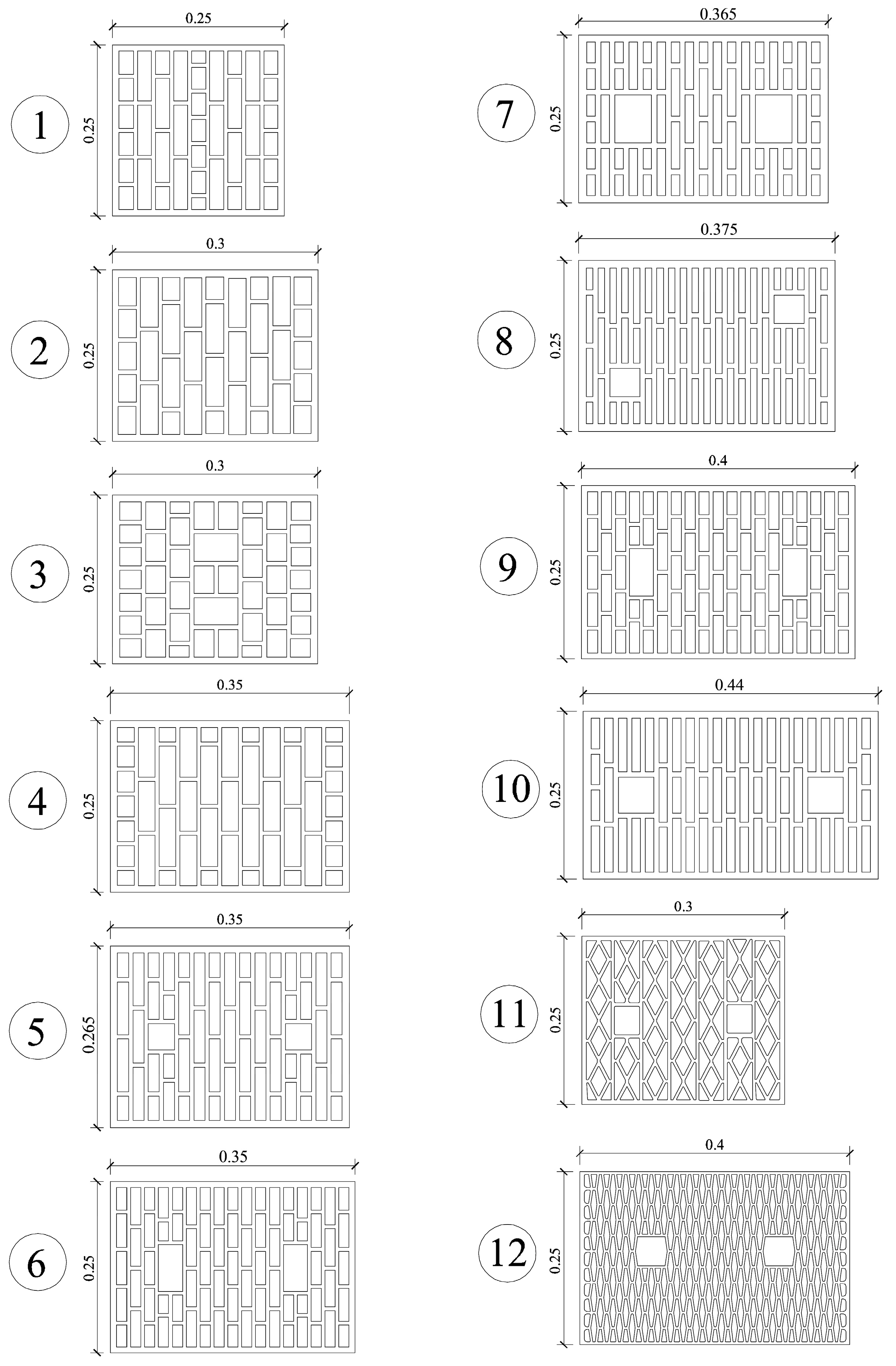
Steady-state analysis to determine the benefits of applying low emissivity coating was performed on several kinds of blocks characterized by different dimensions, geometry and void fractions. To have a sufficient sample in order to be able to discuss the benefits provided by the application, 12 different block geometries (
Figure 1) were evaluated, with several values of total thickness and the number and dimensions of holes. The simulation was also performed with two different values of thermal conductivity of the material, 0.90 W/m·K and 0.45 W/m·K, the first related to a high density clay of 2400 kg/m
3 and the second to a clay with pore density of 1500 kg/m
3. In order to verify the effect of surface emissivity on the overall thermal resistance of the block, the emissivity was varied from 0.9 to 0.1. An emissivity of 0.9 corresponds to the thermal performance of the standard block without coating.
Figure 1.
Images of the evaluated blocks (plan view).
Figure 1.
Images of the evaluated blocks (plan view).
In order to set a reachable limit value, an evaluation without radiative heat exchange was carried out. This case is not real, because it corresponds to an emissivity equal to zero, but it is the lowest value of heat exchange in the cavities, in the case of only a convective heat exchange. The geometric and thermal characteristics of the blocks are reported in
Table 2, which also lists the number of the elements of the meshes and the number of degrees of freedom of the model built in the software.
Figure 1 shows the geometry and the dimensions of the investigated blocks.
Alternative simulations were carried out on blocks with EPS filling (extruded polystyrene; thermal conductivity of 0.04 W/m·K) in the voids in order to obtain a comparison with the B.A.T. (best available technology) of a high thermal performance block.
Finally, the thermal transmittances (
U-value) of a wall built with the evaluated block units have been calculated using the procedure set down in UNI EN 1745 [
22] and UNI EN ISO 6946 [
23]. The
U-value is the most important parameter used to verify the conformity of the wall to national legislation [
24,
25,
26] and to evaluate the thermal heat loss and energy consumption. To evaluate the
U-value, a sample wall has been hypothesized, built with an internal layer of plaster (thickness = 0.02 m; thermal conductivity = 0.4 W/m·K), masonry made with block and a horizontal mortar joint (height = 0.015 m; thermal conductivity of 1.0 W/m·K) and a layer of external plaster (thickness = 0.02 m; thermal conductivity = 0.5 W/m·K). The boundary conditions to evaluate the
U-value were
Rse = 0.04 m
2·K/W and
Rsi = 0.13 m
2·K/W in accordance with the Standard UNI EN ISO 6946 [
23].
Table 2.
Characteristics and thermal proprieties of the investigated blocks.
Table 2.
Characteristics and thermal proprieties of the investigated blocks.
| Sample | Length (m) | Width (m) | Height (m) | Number of voids | Rows of voids | Void fraction | Mesh | Degrees of freedom | Conductivity of the material (W/m·K) |
|---|
| 1A | 0.25 | 0.25 | 0.25 | 39 | 9 | 61.97% | 14,144 | 28,469 | 0.9 |
| 1B | 0.45 |
| 2A | 0.25 | 0.3 | 0.25 | 34 | 9 | 65.19% | 13,532 | 27,251 | 0.9 |
| 2B | 0.45 |
| 3A | 0.25 | 0.3 | 0.25 | 44 | 8 | 62.91% | 13,640 | 27,461 | 0.9 |
| 3B | 0.45 |
| 4A | 0.25 | 0.35 | 0.25 | 45 | 11 | 65.58% | 17,152 | 34,517 | 0.9 |
| 4B | 0.45 |
| 5A | 0.265 | 0.35 | 0.25 | 57 | 15 | 57.25% | 17,888 | 35,977 | 0.9 |
| 5B | 0.45 |
| 6A | 0.25 | 0.35 | 0.25 | 77 | 17 | 59.27% | 20,872 | 41,977 | 0.9 |
| 6B | 0.45 |
| 7A | 0.25 | 0.365 | 0.25 | 64 | 17 | 50.55% | 27,800 | 55,949 | 0.9 |
| 7B | 0.45 |
| 8A | 0.25 | 0.375 | 0.25 | 67 | 21 | 46.03% | 28,152 | 56,641 | 0.9 |
| 8B | 0.45 |
| 9A | 0.25 | 0.4 | 0.25 | 86 | 19 | 60.48% | 26,100 | 52,529 | 0.9 |
| 9B | 0.45 |
| 10A | 0.25 | 0.45 | 0.25 | 61 | 21 | 55.95% | 21,856 | 44,027 | 0.9 |
| 10B | 0.45 |
| 11A | 0.25 | 0.30 | 0.25 | 96 | 21 | 60.63% | 32,516 | 65,235 | 0.9 |
| 11B | 0.45 |
| 12A | 0.25 | 0.40 | 0.25 | 252 | 41 | 57.38% | 44,876 | 90,037 | 0.9 |
| 12B | 0.45 |
3. Results and Discussion
In order to verify the impact of the low emissivity coating on the brick thermal conductivity, the numerical simulations were conducted for different values of emissivity ranging from 0.1 to 0.9. The evaluation shows that the equivalent thermal resistances of the simulated blocks, in comparison with their initial resistance, increase with the decrease in cavity surface emissivity. This decrease in heat exchange is consequent to a reduction in the radiative heat exchange in the voids, due to the low emissivity coating. The reduction in the radiative part causes a decrease in the equivalent thermal conductivity of the cavity, while the convective heat coefficient remains the same in the different evaluations.
As shown in
Table 3, the change in the emissivity of the cavity surfaces leads to a reduction in the equivalent conductivity of the cavities, which is dependent on the emissivities and the dimensions (
b) and (
d) of the cavities. The equivalent conductivity of all three types of cavities drops by between 55% and 60%, when the emissivity is reduced to 0.1, assuming a value between 0.028 and 0.077 W/m·K (while the value in the uncoated block was between 0.062 and 0.232 W/m·K). The best value attainable without radiative heat exchange was 0.025–0.066 W/m·K, corresponding to a reduction of 59%–75%.
Table 3.
Dimensions and equivalent thermal conductivity of the cavities.
Table 3.
Dimensions and equivalent thermal conductivity of the cavities.
| Cavity | d (m) | b (m) | ha (W/m2·K) | λeq (W/m·K) |
|---|
| ε = 0.9 | ε = 0.8 | ε = 0.7 | ε = 0.6 | ε = 0.5 | ε = 0.4 | ε = 0.3 | ε = 0.2 | ε = 0.1 | No radiation |
|---|
| 1-1 | 0.02 | 0.033 | 1.250 | 0.090 | 0.078 | 0.068 | 0.059 | 0.052 | 0.045 | 0.039 | 0.034 | 0.029 | 0.025 |
| 1-2 | 0.02 | 0.073 | 1.250 | 0.099 | 0.085 | 0.073 | 0.064 | 0.055 | 0.047 | 0.041 | 0.035 | 0.030 | 0.025 |
| 1-3 | 0.02 | 0.017 | 1.250 | 0.082 | 0.071 | 0.063 | 0.055 | 0.048 | 0.042 | 0.037 | 0.033 | 0.029 | 0.025 |
| 1-4 | 0.02 | 0.031 | 1.250 | 0.089 | 0.078 | 0.067 | 0.059 | 0.051 | 0.045 | 0.039 | 0.034 | 0.029 | 0.025 |
| 2-1 | 0.026 | 0.041 | 1.250 | 0.117 | 0.101 | 0.088 | 0.077 | 0.067 | 0.058 | 0.051 | 0.044 | 0.038 | 0.033 |
| 2-2 | 0.026 | 0.072 | 1.250 | 0.125 | 0.108 | 0.093 | 0.081 | 0.070 | 0.061 | 0.052 | 0.045 | 0.038 | 0.033 |
| 2-3 | 0.026 | 0.033 | 1.250 | 0.113 | 0.098 | 0.086 | 0.075 | 0.065 | 0.057 | 0.050 | 0.043 | 0.038 | 0.033 |
| 3-1 | 0.031 | 0.027 | 1.250 | 0.128 | 0.111 | 0.097 | 0.085 | 0.075 | 0.066 | 0.058 | 0.051 | 0.0e44 | 0.039 |
| 3-2 | 0.029 | 0.017 | 1.250 | 0.113 | 0.099 | 0.087 | 0.077 | 0.068 | 0.060 | 0.053 | 0.047 | 0.041 | 0.036 |
| 3-3 | 0.029 | 0.04 | 1.250 | 0.128 | 0.111 | 0.096 | 0.084 | 0.073 | 0.064 | 0.056 | 0.049 | 0.042 | 0.036 |
| 3-4 | 0.04 | 0.064 | 1.250 | 0.180 | 0.156 | 0.135 | 0.118 | 0.103 | 0.090 | 0.078 | 0.068 | 0.058 | 0.050 |
| 4-1 | 0.024 | 0.021 | 1.250 | 0.099 | 0.086 | 0.075 | 0.066 | 0.058 | 0.051 | 0.045 | 0.039 | 0.034 | 0.030 |
| 4-2 | 0.024 | 0.031 | 1.250 | 0.105 | 0.091 | 0.079 | 0.069 | 0.060 | 0.053 | 0.046 | 0.040 | 0.035 | 0.030 |
| 4-3 | 0.024 | 0.072 | 1.250 | 0.116 | 0.100 | 0.087 | 0.075 | 0.065 | 0.056 | 0.049 | 0.042 | 0.036 | 0.030 |
| 5-1 | 0.016 | 0.036 | 1.563 | 0.080 | 0.070 | 0.061 | 0.054 | 0.047 | 0.042 | 0.037 | 0.032 | 0.029 | 0.025 |
| 5-2 | 0.016 | 0.077 | 1.563 | 0.086 | 0.074 | 0.065 | 0.057 | 0.050 | 0.043 | 0.038 | 0.033 | 0.029 | 0.025 |
| 5-3 | 0.016 | 0.055 | 1.563 | 0.083 | 0.073 | 0.063 | 0.056 | 0.049 | 0.043 | 0.038 | 0.033 | 0.029 | 0.025 |
| 5-4 | 0.038 | 0.038 | 1.250 | 0.160 | 0.139 | 0.121 | 0.106 | 0.093 | 0.082 | 0.072 | 0.063 | 0.055 | 0.048 |
| 6-1 | 0.015 | 0.033 | 1.667 | 0.076 | 0.067 | 0.059 | 0.052 | 0.046 | 0.041 | 0.036 | 0.032 | 0.028 | 0.025 |
| 6-2 | 0.015 | 0.055 | 1.667 | 0.080 | 0.070 | 0.061 | 0.054 | 0.047 | 0.042 | 0.037 | 0.032 | 0.029 | 0.025 |
| 6-3 | 0.015 | 0.045 | 1.667 | 0.079 | 0.069 | 0.060 | 0.053 | 0.047 | 0.041 | 0.037 | 0.032 | 0.028 | 0.025 |
| 6-4 | 0.035 | 0.068 | 1.250 | 0.161 | 0.140 | 0.121 | 0.105 | 0.092 | 0.080 | 0.069 | 0.060 | 0.051 | 0.044 |
| 7-1 | 0.012 | 0.035 | 2.083 | 0.068 | 0.060 | 0.053 | 0.047 | 0.042 | 0.038 | 0.034 | 0.031 | 0.028 | 0.025 |
| 7-2 | 0.012 | 0.07 | 2.083 | 0.071 | 0.063 | 0.055 | 0.049 | 0.044 | 0.039 | 0.035 | 0.031 | 0.028 | 0.025 |
| 7-3 | 0.053 | 0.07 | 1.250 | 0.232 | 0.201 | 0.175 | 0.153 | 0.134 | 0.117 | 0.102 | 0.089 | 0.077 | 0.066 |
| 8-1 | 0.01 | 0.031 | 2.500 | 0.061 | 0.054 | 0.049 | 0.044 | 0.040 | 0.036 | 0.033 | 0.030 | 0.027 | 0.025 |
| 8-2 | 0.01 | 0.065 | 2.500 | 0.064 | 0.057 | 0.051 | 0.045 | 0.041 | 0.037 | 0.033 | 0.030 | 0.027 | 0.025 |
| 8-3 | 0.01 | 0.081 | 2.500 | 0.064 | 0.057 | 0.051 | 0.046 | 0.041 | 0.037 | 0.033 | 0.030 | 0.028 | 0.025 |
| 8-4 | 0.042 | 0.042 | 1.250 | 0.176 | 0.153 | 0.134 | 0.117 | 0.103 | 0.090 | 0.079 | 0.069 | 0.060 | 0.053 |
| 9-1 | 0.015 | 0.033 | 1.667 | 0.076 | 0.067 | 0.059 | 0.052 | 0.046 | 0.041 | 0.036 | 0.032 | 0.028 | 0.025 |
| 9-2 | 0.015 | 0.054 | 1.667 | 0.080 | 0.070 | 0.061 | 0.054 | 0.047 | 0.042 | 0.037 | 0.032 | 0.029 | 0.025 |
| 9-3 | 0.015 | 0.045 | 1.667 | 0.079 | 0.069 | 0.060 | 0.053 | 0.047 | 0.041 | 0.037 | 0.032 | 0.028 | 0.025 |
| 9-4 | 0.034 | 0.069 | 1.250 | 0.158 | 0.136 | 0.118 | 0.103 | 0.089 | 0.078 | 0.067 | 0.058 | 0.050 | 0.043 |
| 10-1 | 0.013 | 0.045 | 1.923 | 0.073 | 0.064 | 0.056 | 0.050 | 0.044 | 0.040 | 0.035 | 0.031 | 0.028 | 0.025 |
| 10-2 | 0.013 | 0.065 | 1.923 | 0.074 | 0.065 | 0.057 | 0.051 | 0.045 | 0.040 | 0.036 | 0.032 | 0.028 | 0.025 |
| 10-3 | 0.013 | 0.079 | 1.923 | 0.075 | 0.066 | 0.058 | 0.051 | 0.045 | 0.040 | 0.036 | 0.032 | 0.028 | 0.025 |
| 10-4 | 0.052 | 0.052 | 1.250 | 0.218 | 0.190 | 0.166 | 0.145 | 0.128 | 0.112 | 0.098 | 0.086 | 0.075 | 0.065 |
| 11-1 | 0.017 | 0.031 | 1.47 | 0.081 | 0.071 | 0.062 | 0.055 | 0.048 | 0.042 | 0.037 | 0.033 | 0.029 | 0.025 |
| 11-2 | 0,009 | 0.025 | 2.78 | 0.057 | 0.051 | 0.046 | 0.042 | 0.038 | 0.035 | 0.032 | 0.029 | 0.027 | 0.025 |
| 11-3 | 0.010 | 0.054 | 2.50 | 0.063 | 0.056 | 0.050 | 0.045 | 0.041 | 0.037 | 0.033 | 0.030 | 0.027 | 0.025 |
| 11-4 | 0.036 | 0.041 | 1.25 | 0.154 | 0.134 | 0.117 | 0.102 | 0.089 | 0.078 | 0.069 | 0.060 | 0.052 | 0.045 |
| 11-5 | 0.010 | 0.022 | 2.50 | 0.059 | 0.053 | 0.048 | 0.043 | 0.039 | 0.035 | 0.032 | 0.030 | 0.027 | 0.025 |
| 12-1 | 0.008 | 0.018 | 3.13 | 0.053 | 0.047 | 0.043 | 0.039 | 0.036 | 0.033 | 0.031 | 0.029 | 0.027 | 0.025 |
| 12-2 | 0.006 | 0.019 | 4.17 | 0.047 | 0.043 | 0.039 | 0.036 | 0.034 | 0.032 | 0.030 | 0.028 | 0.026 | 0.025 |
| 12-3 | 0.006 | 0.039 | 4.17 | 0.048 | 0.044 | 0.040 | 0.037 | 0.034 | 0.032 | 0.030 | 0.028 | 0.026 | 0.025 |
| 12-4 | 0.044 | 0.042 | 1.25 | 0.184 | 0.160 | 0.140 | 0.122 | 0.107 | 0.094 | 0.083 | 0.072 | 0.063 | 0.055 |
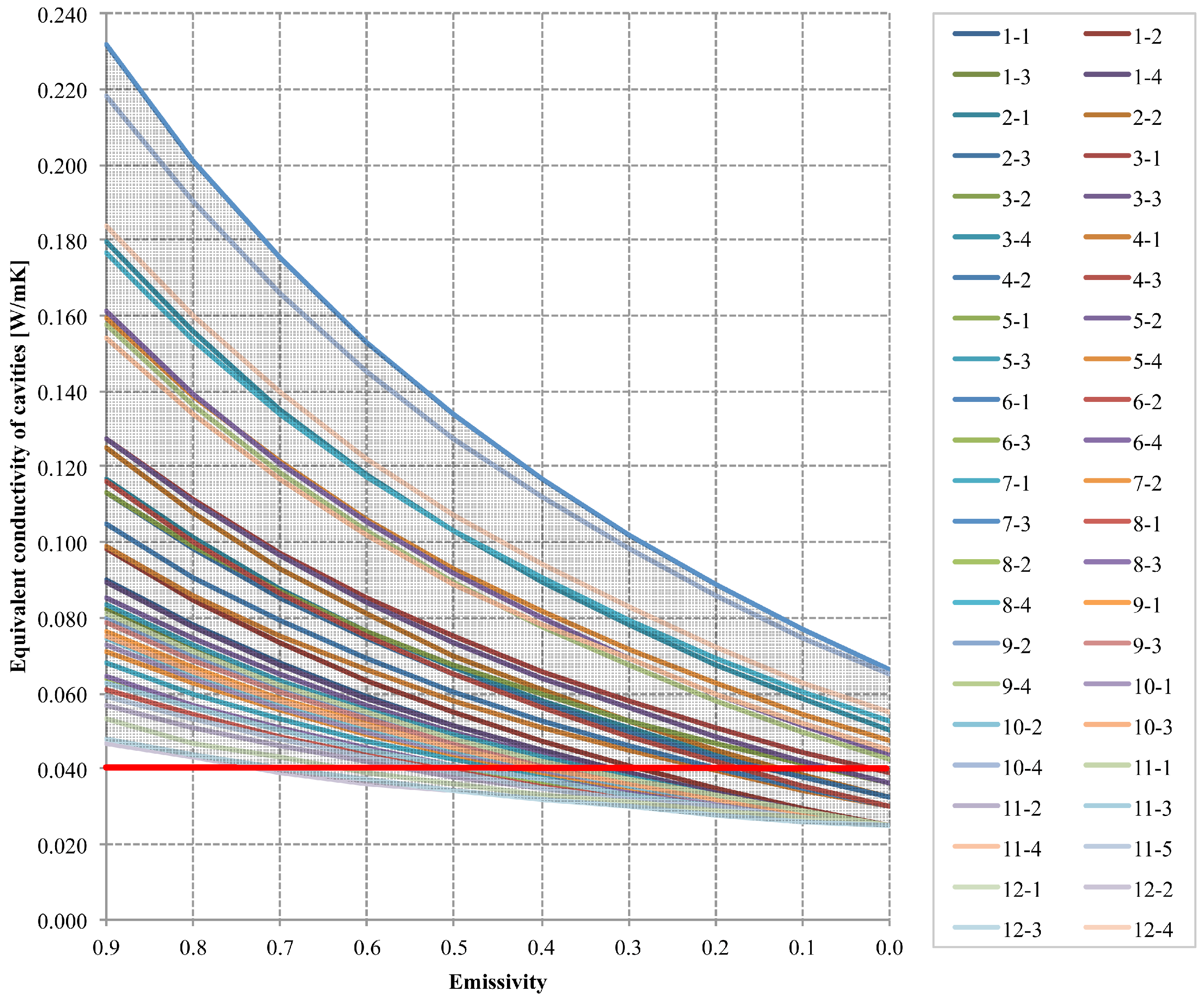
Figure 2 shows the value corresponding to the thermal conductivity of EPS (red line). For most of the enclosures, the value of equivalent thermal conductivity obtained with an emissivity equal to 0.01 is less than the thermal conductivity of the EPS. In particular, if the thickness (
d) of the cavity is less than 0.029 m, the equivalent thermal conductivity is lower than the value of EPS.
Figure 2.
Impact of surface emissivity on the variation in equivalent thermal conductivity of the cavities [red line = thermal conductivity of EPS (extruded polystyrene)].
Figure 2.
Impact of surface emissivity on the variation in equivalent thermal conductivity of the cavities [red line = thermal conductivity of EPS (extruded polystyrene)].
Values of thermal resistance of the evaluated block are shown in
Table 4. A reduction in the equivalent thermal conductivity of the enclosures produces an increase in the thermal resistance value of the block of +32%–82% (
Table 5), from values of 2.65–0.96 m
2·K/W (ε = 0.9) to values of 4.20–1.34 m
2·K/W (ε = 0.1) (
Table 4).
Table 4.
Thermal resistance of the evaluated block (m2·K/W).
Table 4.
Thermal resistance of the evaluated block (m2·K/W).
| Sample | ε = 0.90 | ε = 0.80 | ε = 0.70 | ε = 0.60 | ε = 0.50 | ε = 0.40 | ε = 0.30 | ε = 0.20 | ε = 0.10 | No radiation | EPS |
|---|
| 1A | 1.04 | 1.11 | 1.18 | 1.25 | 1.33 | 1.38 | 1.45 | 1.51 | 1.57 | 1.64 | 1.45 |
| 1B | 1.46 | 1.58 | 1.71 | 1.84 | 1.97 | 2.12 | 2.25 | 2.39 | 2.54 | 2.70 | 2.26 |
| 2A | 1.14 | 1.22 | 1.31 | 1.39 | 1.47 | 1.55 | 1.63 | 1.70 | 1.79 | 1.82 | 1.76 |
| 2B | 1.55 | 1.70 | 1.84 | 1.99 | 2.15 | 2.30 | 2.47 | 2.64 | 2.83 | 2.92 | 2.77 |
| 3A | 0.96 | 1.02 | 1.07 | 1.12 | 1.17 | 1.21 | 1.25 | 1.29 | 1.34 | 1.35 | 1.34 |
| 3B | 1.39 | 1.49 | 1.59 | 1.70 | 1.80 | 1.90 | 2.00 | 2.09 | 2.20 | 2.30 | 2.27 |
| 4A | 1.39 | 1.50 | 1.59 | 1.70 | 1.79 | 1.89 | 1.98 | 2.08 | 2.17 | 2.25 | 2.11 |
| 4B | 1.90 | 2.08 | 2.25 | 2.44 | 2.62 | 2.82 | 3.01 | 3.22 | 3.43 | 3.68 | 3.28 |
| 5A | 1.55 | 1.65 | 1.75 | 1.84 | 1.93 | 2.03 | 2.12 | 2.21 | 2.29 | 2.37 | 2.09 |
| 5B | 2.15 | 2.33 | 2.51 | 2.68 | 2.87 | 3.07 | 3.25 | 3.45 | 3.63 | 3.84 | 3.20 |
| 6A | 1.57 | 1.66 | 1.76 | 1.84 | 1.93 | 2.00 | 2.08 | 2.17 | 2.24 | 2.30 | 2.06 |
| 6B | 2.22 | 2.39 | 2.57 | 2.73 | 2.92 | 3.08 | 3.25 | 3.45 | 3.58 | 3.78 | 3.21 |
| 7A | 1.39 | 1.45 | 1.53 | 1.59 | 1.65 | 1.71 | 1.76 | 1.82 | 1.86 | 1.91 | 1.75 |
| 7B | 2.03 | 2.16 | 2.30 | 2.43 | 2.55 | 2.68 | 2.80 | 2.93 | 3.04 | 3.17 | 2.79 |
| 8A | 1.57 | 1.64 | 1.71 | 1.77 | 1.84 | 1.91 | 1.97 | 2.02 | 2.07 | 1.88 | 1.88 |
| 8B | 2.28 | 2.41 | 2.53 | 2.69 | 2.82 | 2.95 | 3.09 | 3.21 | 3.33 | 3.45 | 2.90 |
| 9A | 1.76 | 1.87 | 1.97 | 2.07 | 2.17 | 2.25 | 2.34 | 2.43 | 2.49 | 2.59 | 2.34 |
| 9B | 2.48 | 2.67 | 2.87 | 3.06 | 3.27 | 3.45 | 3.65 | 3.86 | 4.03 | 4.24 | 3.58 |
| 10A | 1.87 | 1.97 | 2.08 | 2.17 | 2.27 | 2.36 | 2.44 | 2.52 | 2.61 | 2.68 | 2.40 |
| 10B | 2.65 | 2.84 | 3.04 | 3.23 | 3.43 | 3.62 | 3.80 | 3.99 | 4.20 | 4.38 | 3.73 |
| 11A | 1.70 | 1.78 | 1.85 | 1.93 | 1.99 | 2.05 | 2.12 | 2.17 | 2.23 | 2.28 | 2.03 |
| 11B | 2.33 | 2.49 | 2.63 | 2.79 | 2.91 | 3.05 | 3.20 | 3.33 | 3.47 | 3.58 | 3.02 |
| 12A | 2.77 | 2.89 | 3.01 | 3.11 | 3.21 | 3.29 | 3.37 | 3.46 | 3.55 | 3.60 | 3.07 |
| 12B | 3.73 | 3.93 | 4.16 | 4.34 | 4.55 | 4.70 | 4.86 | 5.05 | 5.24 | 5.35 | 4.28 |
Table 5.
Thermal resistance of the evaluated block: percentage of improvement.
Table 5.
Thermal resistance of the evaluated block: percentage of improvement.
| Sample | ε = 0.90 | ε = 0.80 | ε = 0.70 | ε = 0.60 | ε = 0.50 | ε = 0.40 | ε = 0.30 | ε = 0.20 | ε = 0.10 | No radiation | EPS |
|---|
| 1A | 100% | 107% | 114% | 120% | 128% | 133% | 139% | 145% | 151% | 157% | 140% |
| 1B | 100% | 109% | 118% | 126% | 135% | 145% | 154% | 164% | 174% | 185% | 155% |
| 2A | 100% | 107% | 115% | 122% | 129% | 135% | 143% | 149% | 156% | 160% | 154% |
| 2B | 100% | 109% | 119% | 128% | 138% | 148% | 159% | 170% | 182% | 188% | 178% |
| 3A | 100% | 106% | 111% | 116% | 121% | 126% | 130% | 134% | 139% | 140% | 139% |
| 3B | 100% | 107% | 115% | 122% | 130% | 137% | 144% | 151% | 159% | 166% | 164% |
| 4A | 100% | 107% | 114% | 122% | 129% | 136% | 142% | 149% | 156% | 162% | 151% |
| 4B | 100% | 109% | 118% | 128% | 138% | 148% | 158% | 169% | 180% | 193% | 172% |
| 5A | 100% | 107% | 113% | 119% | 125% | 132% | 137% | 143% | 148% | 154% | 135% |
| 5B | 100% | 109% | 117% | 125% | 134% | 143% | 151% | 161% | 169% | 179% | 149% |
| 6A | 100% | 106% | 112% | 117% | 123% | 128% | 133% | 138% | 143% | 147% | 131% |
| 6B | 100% | 108% | 116% | 123% | 131% | 139% | 147% | 155% | 162% | 171% | 145% |
| 7A | 100% | 105% | 110% | 115% | 119% | 123% | 127% | 131% | 134% | 138% | 126% |
| 7B | 100% | 106% | 113% | 119% | 125% | 132% | 138% | 144% | 150% | 156% | 137% |
| 8A | 100% | 105% | 109% | 113% | 118% | 122% | 126% | 129% | 132% | 120% | 120% |
| 8B | 100% | 106% | 111% | 118% | 124% | 130% | 136% | 141% | 147% | 151% | 127% |
| 9A | 100% | 106% | 112% | 117% | 123% | 128% | 133% | 138% | 141% | 147% | 132% |
| 9B | 100% | 108% | 116% | 123% | 132% | 139% | 147% | 156% | 162% | 171% | 144% |
| 10A | 100% | 106% | 111% | 116% | 122% | 126% | 130% | 135% | 140% | 143% | 129% |
| 10B | 100% | 107% | 115% | 122% | 130% | 137% | 143% | 151% | 158% | 165% | 141% |
| 11A | 100% | 105% | 109% | 114% | 117% | 121% | 125% | 128% | 131% | 134% | 120% |
| 11B | 100% | 107% | 113% | 119% | 125% | 131% | 137% | 143% | 149% | 154% | 129% |
| 12A | 100% | 104% | 108% | 112% | 116% | 119% | 122% | 125% | 128% | 130% | 111% |
| 12B | 100% | 105% | 111% | 116% | 122% | 126% | 130% | 135% | 140% | 143% | 115% |
Table 6 shows the values of the equivalent thermal conductivity of the analyzed block, which is derived by dividing the thickness of a block by its thermal resistance. While for the standard block (ε = 0.9), the equivalent thermal conductivity obtained is between 0.311 and 0.157 W/m·K, for the improved block (ε = 0.1), the values are 0.224–0.096 W/m·K, corresponding to a reduction of 24%–45% (
Table 7). The equivalent conductivity of the block without radiative heat exchange was 0.222–0.091 W/m·K, corresponding to a reduction of 17%–48%. For the block with polystyrene, the value of equivalent conductivity calculated is 0.224–0.150 W/m·K. All of the blocks evaluated with a low emissivity coating of 0.1 have a thermal behavior equal to or higher than the block simulated with the polystyrene inside the void. The block with EPS has the same behavior as the block with low emissivity coating for a surface emissivity between 0.4 and 0.1. The mean value of the reduction in the equivalent thermal conductivity obtained for an emissivity equal to 0.1 is 35%, compared with 30% for the block with EPS inside the cavity.
Table 6.
Equivalent thermal conductivity of the evaluated block (W/m·K).
Table 6.
Equivalent thermal conductivity of the evaluated block (W/m·K).
| Sample | ε = 0.90 | ε = 0.80 | ε = 0.70 | ε = 0.60 | ε = 0.50 | ε = 0.40 | ε = 0.30 | ε = 0.20 | ε = 0.10 | No radiation | EPS |
|---|
| 1A | 0.240 | 0.225 | 0.211 | 0.201 | 0.188 | 0.181 | 0.173 | 0.166 | 0.159 | 0.153 | 0.172 |
| 1B | 0.171 | 0.158 | 0.146 | 0.136 | 0.127 | 0.118 | 0.111 | 0.104 | 0.098 | 0.093 | 0.111 |
| 2A | 0.263 | 0.245 | 0.229 | 0.216 | 0.204 | 0.194 | 0.184 | 0.176 | 0.168 | 0.164 | 0.170 |
| 2B | 0.193 | 0.177 | 0.163 | 0.151 | 0.140 | 0.130 | 0.121 | 0.114 | 0.106 | 0.103 | 0.108 |
| 3A | 0.311 | 0.295 | 0.280 | 0.268 | 0.257 | 0.248 | 0.239 | 0.232 | 0.224 | 0.222 | 0.224 |
| 3B | 0.217 | 0.201 | 0.188 | 0.177 | 0.167 | 0.158 | 0.150 | 0.143 | 0.136 | 0.130 | 0.132 |
| 4A | 0.251 | 0.234 | 0.220 | 0.206 | 0.195 | 0.185 | 0.177 | 0.168 | 0.161 | 0.155 | 0.166 |
| 4B | 0.184 | 0.169 | 0.156 | 0.144 | 0.133 | 0.124 | 0.116 | 0.109 | 0.102 | 0.095 | 0.107 |
| 5A | 0.227 | 0.212 | 0.200 | 0.190 | 0.181 | 0.172 | 0.165 | 0.158 | 0.153 | 0.147 | 0.167 |
| 5B | 0.163 | 0.150 | 0.140 | 0.131 | 0.122 | 0.114 | 0.108 | 0.101 | 0.096 | 0.091 | 0.109 |
| 6A | 0.223 | 0.210 | 0.199 | 0.190 | 0.181 | 0.175 | 0.168 | 0.162 | 0.156 | 0.152 | 0.170 |
| 6B | 0.158 | 0.147 | 0.136 | 0.128 | 0.120 | 0.114 | 0.108 | 0.102 | 0.098 | 0.092 | 0.109 |
| 7A | 0.263 | 0.251 | 0.239 | 0.230 | 0.222 | 0.214 | 0.207 | 0.201 | 0.196 | 0.191 | 0.209 |
| 7B | 0.180 | 0.169 | 0.159 | 0.150 | 0.143 | 0.136 | 0.130 | 0.125 | 0.120 | 0.115 | 0.131 |
| 8A | 0.239 | 0.229 | 0.219 | 0.212 | 0.203 | 0.197 | 0.190 | 0.185 | 0.181 | 0.200 | 0.200 |
| 8B | 0.165 | 0.155 | 0.148 | 0.139 | 0.133 | 0.127 | 0.121 | 0.117 | 0.112 | 0.109 | 0.129 |
| 9A | 0.227 | 0.214 | 0.203 | 0.194 | 0.185 | 0.178 | 0.171 | 0.164 | 0.161 | 0.155 | 0.171 |
| 9B | 0.161 | 0.150 | 0.139 | 0.131 | 0.122 | 0.116 | 0.110 | 0.104 | 0.099 | 0.094 | 0.112 |
| 10A | 0.241 | 0.228 | 0.217 | 0.207 | 0.198 | 0.191 | 0.185 | 0.179 | 0.173 | 0.168 | 0.187 |
| 10B | 0.170 | 0.158 | 0.148 | 0.139 | 0.131 | 0.124 | 0.119 | 0.113 | 0.107 | 0.103 | 0.121 |
| 11A | 0.177 | 0.169 | 0.162 | 0.155 | 0.151 | 0.146 | 0.142 | 0.138 | 0.134 | 0.132 | 0.148 |
| 11B | 0.129 | 0.121 | 0.114 | 0.108 | 0.103 | 0.098 | 0.094 | 0.090 | 0.087 | 0.084 | 0.099 |
| 12A | 0.144 | 0.139 | 0.133 | 0.129 | 0.124 | 0.122 | 0.119 | 0.116 | 0.113 | 0.111 | 0.130 |
| 12B | 0.107 | 0.102 | 0.096 | 0.092 | 0.088 | 0.085 | 0.082 | 0.079 | 0.076 | 0.075 | 0.093 |
Table 7.
Equivalent thermal conductivity of the evaluated block: percentage of reduction.
Table 7.
Equivalent thermal conductivity of the evaluated block: percentage of reduction.
| Sample | ε = 0.90 | ε = 0.80 | ε = 0.70 | ε = 0.60 | ε = 0.50 | ε = 0.40 | ε = 0.30 | ε = 0.20 | ε = 0.10 | No radiation | EPS |
|---|
| 1A | 0% | −6% | −12% | −17% | −22% | −25% | −28% | −31% | −34% | −36% | −28% |
| 1B | 0% | −8% | −15% | −21% | −26% | −31% | −35% | −39% | −43% | −46% | −35% |
| 2A | 0% | −7% | −13% | −18% | −22% | −26% | −30% | −33% | −36% | −37% | −35% |
| 2B | 0% | −8% | −16% | −22% | −28% | −32% | −37% | −41% | −45% | −47% | −44% |
| 3A | 0% | −5% | −10% | −14% | −17% | −20% | −23% | −26% | −28% | −29% | −28% |
| 3B | 0% | −7% | −13% | −18% | −23% | −27% | −31% | −34% | −37% | −40% | −39% |
| 4A | 0% | −7% | −13% | −18% | −22% | −26% | −30% | −33% | −36% | −38% | −34% |
| 4B | 0% | −8% | −15% | −22% | −27% | −33% | −37% | −41% | −45% | −48% | −42% |
| 5A | 0% | −6% | −12% | −16% | −20% | −24% | −27% | −30% | −32% | −35% | −26% |
| 5B | 0% | −8% | −14% | −20% | −25% | −30% | −34% | −38% | −41% | −44% | −33% |
| 6A | 0% | −6% | −11% | −15% | −19% | −22% | −25% | −27% | −30% | −32% | −24% |
| 6B | 0% | −7% | −14% | −19% | −24% | −28% | −32% | −36% | −38% | −41% | −31% |
| 7A | 0% | −5% | −9% | −13% | −16% | −19% | −21% | −24% | −26% | −27% | −21% |
| 7B | 0% | −6% | −12% | −16% | −20% | −24% | −27% | −31% | −33% | −36% | −27% |
| 8A | 0% | −4% | −8% | −12% | −15% | −18% | −20% | −23% | −24% | −17% | −17% |
| 8B | 0% | −6% | −10% | −15% | −19% | −23% | −26% | −29% | −32% | −34% | −22% |
| 9A | 0% | −6% | −11% | −15% | −19% | −22% | −25% | −28% | −29% | −32% | −24% |
| 9B | 0% | −7% | −14% | −19% | −24% | −28% | −32% | −36% | −38% | −41% | −31% |
| 10A | 0% | −5% | −10% | −14% | −18% | −21% | −23% | −26% | −28% | −30% | −22% |
| 10B | 0% | −7% | −13% | −18% | −23% | −27% | −30% | −34% | −37% | −39% | −29% |
| 11A | 0% | −4% | −8% | −12% | −14% | −17% | −20% | −22% | −24% | −25% | −16% |
| 11B | 0% | −6% | −11% | −16% | −20% | −23% | −27% | −30% | −33% | −35% | −23% |
| 12A | 0% | −4% | −8% | −11% | −14% | −16% | −18% | −20% | −22% | −23% | −10% |
| 12B | 0% | −5% | −10% | −14% | −18% | −21% | −23% | −26% | −29% | −30% | −13% |
Table 8 shows the
U-value of the walls built with the evaluated blocks, calculated considering a hypothetical configuration of the layers (external plaster, masonry with horizontal mortar and internal plaster). While for the standard block (ε = 0.9), the value of thermal transmittance is between 0.32–0.87 W/m
2·K, for the improved block (ε = 0.1), the values are 0.26–0.69 W/m
2·K, corresponding to a reduction of 18%–37% (
Table 9). For the block with polystyrene, the
U-value calculated is 0.29–0.69 W/m
2·K.
The comparison with the two previous evaluations [
18,
19] offers insight into whether the percentages of improvement found in this paper could be extended to other kinds of brick or block, with different geometric and material properties.
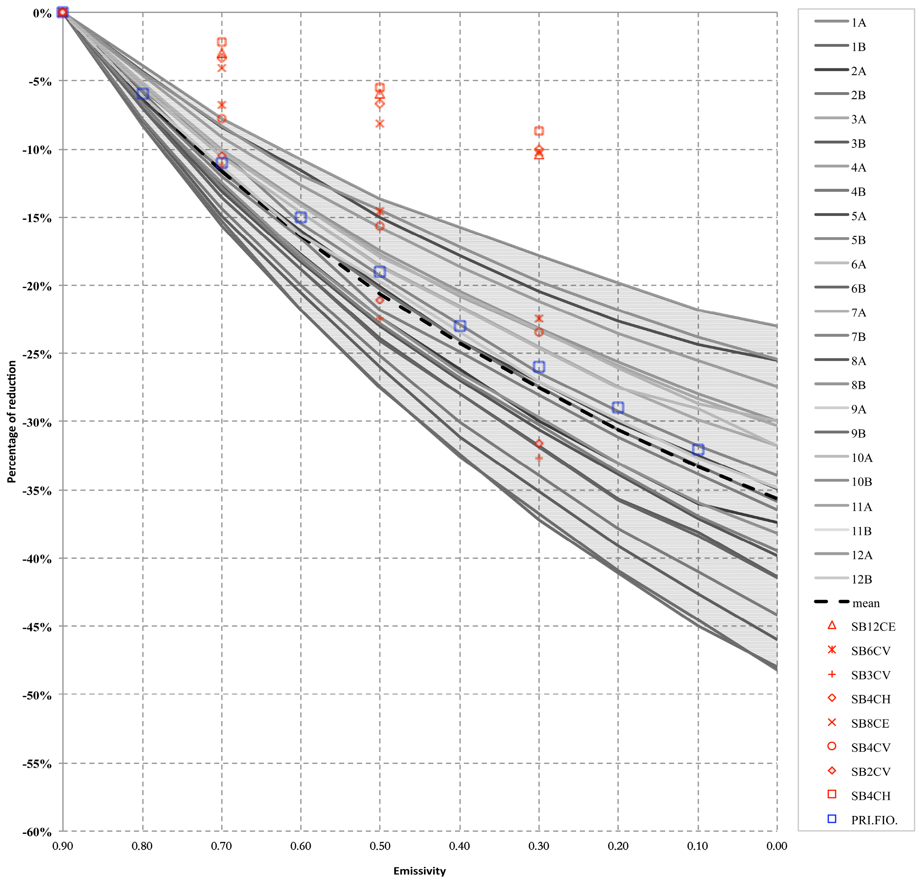
Figure 3 shows the values of reduction obtained in this work compared with the values obtained in a previous analysis, using the same methodology, but carried out on a different block, and an analysis carried out on walls made with traditional bricks. The results obtained in the previous study [
19] do not differ greatly from the values obtained in the present work, with a variation of less than 3% with respect to the mean values.
On the contrary, the comparison made with a previous analysis [
18] carried out on walls with traditional brick indicates a substantial difference. In fact, only four of the eight walls analyzed have a behavior that is comparable with the mean values obtained in the present work (difference < 6%), while for the remaining walls, the values obtained are clearly different.
The possible causes of these differences are:
evaluation made considering not only the brick but also the mortar;
dimension of the cavity and the block;
percentage of voids;
number of voids;
thermal conductivity of the clay.
Further analysis has been suggested in order to evaluate the performance of a large number of samples that could represent most of the blocks or bricks available on the market. The evaluation of the impact of the surface emissivity on the U-value of the wall could also be useful in order to investigate energy consumption and economic benefits, under real conditions.
Table 8.
Overall thermal transmittance of the wall built with the evaluated block (W/m2·K).
Table 8.
Overall thermal transmittance of the wall built with the evaluated block (W/m2·K).
| Sample | ε = 0.90 | ε = 0.80 | ε = 0.70 | ε = 0.60 | ε = 0.50 | ε = 0.40 | ε = 0.30 | ε = 0.20 | ε = 0.10 | No radiation | EPS |
|---|
| 1A | 0.84 | 0.80 | 0.76 | 0.74 | 0.70 | 0.68 | 0.66 | 0.64 | 0.63 | 0.61 | 0.66 |
| 1B | 0.66 | 0.62 | 0.59 | 0.56 | 0.53 | 0.51 | 0.49 | 0.47 | 0.45 | 0.43 | 0.49 |
| 2A | 0.77 | 0.74 | 0.70 | 0.67 | 0.65 | 0.62 | 0.60 | 0.58 | 0.56 | 0.55 | 0.57 |
| 2B | 0.62 | 0.58 | 0.55 | 0.52 | 0.49 | 0.47 | 0.45 | 0.43 | 0.41 | 0.40 | 0.41 |
| 3A | 0.87 | 0.84 | 0.81 | 0.78 | 0.76 | 0.74 | 0.72 | 0.71 | 0.69 | 0.69 | 0.69 |
| 3B | 0.67 | 0.64 | 0.61 | 0.58 | 0.56 | 0.54 | 0.52 | 0.50 | 0.48 | 0.47 | 0.47 |
| 4A | 0.66 | 0.63 | 0.60 | 0.58 | 0.55 | 0.53 | 0.51 | 0.50 | 0.48 | 0.47 | 0.49 |
| 4B | 0.53 | 0.50 | 0.47 | 0.44 | 0.42 | 0.40 | 0.38 | 0.36 | 0.35 | 0.33 | 0.36 |
| 5A | 0.62 | 0.59 | 0.56 | 0.54 | 0.52 | 0.50 | 0.49 | 0.47 | 0.46 | 0.45 | 0.49 |
| 5B | 0.48 | 0.46 | 0.43 | 0.41 | 0.39 | 0.38 | 0.36 | 0.35 | 0.34 | 0.32 | 0.37 |
| 6A | 0.61 | 0.58 | 0.56 | 0.54 | 0.52 | 0.51 | 0.50 | 0.48 | 0.47 | 0.46 | 0.50 |
| 6B | 0.47 | 0.45 | 0.43 | 0.41 | 0.39 | 0.38 | 0.36 | 0.35 | 0.34 | 0.33 | 0.36 |
| 7A | 0.66 | 0.64 | 0.62 | 0.60 | 0.59 | 0.57 | 0.56 | 0.55 | 0.54 | 0.52 | 0.56 |
| 7B | 0.50 | 0.48 | 0.46 | 0.44 | 0.43 | 0.41 | 0.40 | 0.39 | 0.38 | 0.37 | 0.40 |
| 8A | 0.61 | 0.59 | 0.57 | 0.55 | 0.54 | 0.52 | 0.51 | 0.50 | 0.49 | 0.48 | 0.53 |
| 8B | 0.46 | 0.44 | 0.43 | 0.41 | 0.40 | 0.38 | 0.37 | 0.36 | 0.35 | 0.34 | 0.39 |
| 9A | 0.55 | 0.53 | 0.51 | 0.49 | 0.47 | 0.46 | 0.45 | 0.44 | 0.43 | 0.42 | 0.45 |
| 9B | 0.43 | 0.41 | 0.39 | 0.37 | 0.35 | 0.34 | 0.33 | 0.31 | 0.31 | 0.30 | 0.33 |
| 10A | 0.52 | 0.50 | 0.48 | 0.47 | 0.45 | 0.44 | 0.43 | 0.42 | 0.41 | 0.40 | 0.43 |
| 10B | 0.40 | 0.38 | 0.37 | 0.35 | 0.34 | 0.32 | 0.31 | 0.30 | 0.29 | 0.28 | 0.32 |
| 11A | 0.58 | 0.56 | 0.55 | 0.53 | 0.52 | 0.51 | 0.50 | 0.49 | 0.48 | 0.47 | 0.51 |
| 11B | 0.46 | 0.44 | 0.43 | 0.41 | 0.40 | 0.39 | 0.37 | 0.36 | 0.35 | 0.35 | 0.39 |
| 12A | 0.40 | 0.39 | 0.37 | 0.37 | 0.36 | 0.35 | 0.35 | 0.34 | 0.33 | 0.33 | 0.37 |
| 12B | 0.32 | 0.31 | 0.30 | 0.29 | 0.28 | 0.28 | 0.27 | 0.26 | 0.26 | 0.25 | 0.29 |
Figure 3.
Comparison between the impacts of surface emissivity on the variation in equivalent thermal conductivity of the blocks obtained in the present work (grey lines) and in a previous investigation (red point [
18], blue point [
19]).
Figure 3.
Comparison between the impacts of surface emissivity on the variation in equivalent thermal conductivity of the blocks obtained in the present work (grey lines) and in a previous investigation (red point [
18], blue point [
19]).
Table 9.
Overall thermal transmittance of the wall built with the evaluated block: percentage of reduction.
Table 9.
Overall thermal transmittance of the wall built with the evaluated block: percentage of reduction.
| Sample | ε = 0.90 | ε = 0.80 | ε = 0.70 | ε = 0.60 | ε = 0.50 | ε = 0.40 | ε = 0.30 | ε = 0.20 | ε = 0.10 | No radiation | EPS |
|---|
| 1A | 0% | −5% | −9% | −12% | −16% | −18% | −21% | −23% | −25% | −27% | −21% |
| 1B | 0% | −6% | −11% | −15% | −19% | −23% | −26% | −29% | −32% | −35% | −26% |
| 2A | 0% | −5% | −9% | −13% | −16% | −19% | −22% | −25% | −27% | −28% | −27% |
| 2B | 0% | −6% | −11% | −16% | −21% | −24% | −28% | −31% | −34% | −36% | −34% |
| 3A | 0% | −4% | −7% | −10% | −13% | −15% | −17% | −19% | −21% | −21% | −21% |
| 3B | 0% | −5% | −10% | −13% | −17% | −20% | −23% | −26% | −28% | −30% | −30% |
| 4A | 0% | −5% | −9% | −13% | −17% | −20% | −23% | −25% | −28% | −29% | −26% |
| 4B | 0% | −6% | −11% | −16% | −21% | −25% | −28% | −31% | −34% | −37% | −32% |
| 5A | 0% | −5% | −9% | −12% | −15% | −18% | −20% | −23% | −25% | −27% | −20% |
| 5B | 0% | −6% | −11% | −15% | −19% | −22% | −25% | −28% | −31% | −33% | −25% |
| 6A | 0% | −4% | −8% | −11% | −14% | −16% | −18% | −21% | −23% | −24% | −18% |
| 6B | 0% | −5% | −10% | −14% | −18% | −21% | −24% | −27% | −29% | −31% | −23% |
| 7A | 0% | −3% | −7% | −9% | −12% | −14% | −16% | −18% | −19% | −21% | −16% |
| 7B | 0% | −4% | −9% | −12% | −15% | −18% | −21% | −23% | −25% | −27% | −20% |
| 8A | 0% | −3% | −6% | −9% | −11% | −13% | −15% | −17% | −18% | −19% | −12% |
| 8B | 0% | −4% | −7% | −11% | −14% | −17% | −20% | −22% | −24% | −25% | −16% |
| 9A | 0% | −4% | −8% | −11% | −14% | −16% | −19% | −21% | −22% | −24% | −19% |
| 9B | 0% | −5% | −10% | −14% | −18% | −21% | −24% | −27% | −29% | −31% | −23% |
| 10A | 0% | −4% | −8% | −11% | −13% | −16% | −18% | −20% | −22% | −23% | −17% |
| 10B | 0% | −5% | −10% | −13% | −17% | −20% | −23% | −25% | −28% | −30% | −22% |
| 11A | 0% | −3% | −6% | −9% | −11% | −13% | −15% | −16% | −18% | −19% | −12% |
| 11B | 0% | −4% | −8% | −12% | −14% | −17% | −20% | −22% | −24% | −25% | −16% |
| 12A | 0% | −3% | −6% | −8% | −10% | −11% | −13% | −14% | −16% | −17% | −7% |
| 12B | 0% | −4% | −7% | −10% | −12% | −14% | −16% | −18% | −20% | −21% | −9% |
4. Conclusions
This paper presents the evaluation of the thermal performance of hollow clay bricks and blocks with low emissivity treatment of the internal cavity surfaces.
The numerical evaluation was carried out in order to determine the increase in the thermal resistance provided by low emissivity coating applied on the void surfaces of the brick. For the evaluation, a set of 20 samples was investigated, characterized by different shapes and the thermal conductivity of the materials. Each sample was simulated for surface emissivities of 0.9–0.1. The values obtained with the numerical simulation were compared with the standard block and with the block insulated with EPS in the voids.
The results showed that a low emissivity coating leads to an increase in the thermal resistance provided by the block, through the reduction in the radiative heat exchange in the voids. Using the low emissivity coating, it is possible to reduce the equivalent thermal conductivity of the cavities by between 55%–70% (ε = 0.1) to a value of 0.027 W/m·K, which is lower than the thermal conductivity of common thermal insulation.
The effect of the reduction in the thermal heat exchange in the void has a significant impact on the thermal resistance of the block. In fact, the results show that the application of low emissivity coating could reduce the equivalent thermal conductivity of the block by at least 24% (for an emissivity of 0.1). The consequent reduction in the U-value of a wall built with the improved blocks is 18%–37%.
In all cases, the thermal behavior of the treated block is improved with respect to the standard block, and with an emissivity of 0.1, it is better than the block insulated with polystyrene.
The theoretical procedure to calculate the thermal performance of the block is easily repeatable and is employed to verify conformity with the current standard.
Further studies are suggested to include a wide range of blocks, to test the real emissivity of the coated surface with different kinds of coating and to evaluate performance decay in real conditions.

