
Hybrid Tri-Cure Organo-Silicon Coatings for Monument Preservation


Department of Chemistry and Center for Photochemical Sciences, Bowling Green State University, Bowling Green, OH 43403, USA
*
Author to whom correspondence should be addressed.
Coatings 2022, 12(8), 1098; https://doi.org/10.3390/coatings12081098
Submission received: 28 June 2022
/
Revised: 26 July 2022
/
Accepted: 30 July 2022
/
Published: 2 August 2022
(This article belongs to the Special Issue Advanced Coating Material for Heritage Preservation)
Abstract
:A coating system integrating three distinct chemistries was developed to protect materials used in monuments and construction. Initial curing is achieved using a UV-initiated thiol-ene reaction to form a non-impressionable/non-sticky surface. Second, amine/epoxy reactions form a firm surface adhesion and give mechanical strength through consolidation. Third, alkoxysilane sol-gel curing integrates the siloxane network while adding thermal stability, hydrophobicity, and a hardened surface. The final design utilizes a photoacid generator to increase the reaction speed of the second and third curing steps. The coating can be applied by spray, dip, or wipe on methods and exhibits a rapid non-impressionable surface (as fast as 10 min) that resists graffiti and environmental conditions, and is used and stored as a single-component system with a pot life exceeding six months. A series of experiments were used to determine the coating properties and durability, including field testing and accelerated weathering.
1. Introduction
Monuments are objects or places established for cultural or historical significance meant as reminders to future generations of lost individuals, outstanding accomplishments, or important events across the world. Commonly, these gravesites, statues, sculptures, buildings, and locations are constructed using various types of stones and metals to ensure the durability of the intended meaning. Many renowned ancient monuments such as Newgrange and the Great Sphinx of Giza have survived for thousands of years to the modern-day due to their stone construction; however, they have lost much of their original detail due to erosion of their sandstone and limestone components [1,2]. In the United States, many monuments are constructed to remember lost loved ones [3,4], events [5], honor great people [6,7], and even denote property boundaries [8]. The cost of these structures has a great range depending on the scale, from thousands of dollars for gravestones [3,4] to millions for national monuments [5,6,7], where private and/or public funding often pay for the cost.
With the expense required for installation, these entities must be adequately protected from environmental damage. There are three main erosion issues that monuments must persist through. First, acid rain can deteriorate the stone surfaces through dissolution (stone dissolved), or chemically alter surfaces through reactions with sulfur dioxide, forming discoloration and weakening the structure. Both of these processes are most detrimental to calcium-containing stones [9,10,11]. Oxidation is the second issue that affects metals, causing them to form metal oxides on the surface, weakening structural integrity, and causing discoloration, an example being The Statue of Liberty [9]. The third issue comes from fouling, when biological growth, such as lichens or mosses, produce acid on the stone’s surface, causing local erosion [9,12,13]. When choosing how to protect monuments best, all three issues should be considered.
Historically, the preferred conservation method has been to use a series of surface coatings [9,10]. Many different systems have been adopted from use in other industrial applications due to their success (i.e., floor or automotive coatings) [14,15,16]. Organic polymers like epoxy resins, acrylates, and fluoropolymers have been used for this purpose due to their hydrophobic and protective capabilities, but they fall short in some areas when used individually [9,10,13,14,17,18]. While epoxies offer excellent surface penetration and mechanical strength, they are susceptible to photoinduced oxidation, discoloration, biological surface growth, are two-component systems, and have short working times [9,13,14]. Bisphenol A (dian) and cycloaliphatic epoxy systems are especially known to discolor and undergo oxidation over time [13]. Acrylics often offer surface reinforcement, are photostable, and may have anti-fouling capabilities, but they tend to be hard to remove and take a long time to cure [9,13,14]. Fluoropolymers provide a highly hydrophobic surface with photostability, but the hydrophobicity can make them difficult to handle, incompatible with many surfaces and environmentally unfavorable [14,18,19]. Despite this, there are numerous perfluoro compounds, both linear chains and cyclics such as perfluoropyridyls, which have increased the compatibility of these molecules with polymeric systems including siloxane networks [20,21]. The usage of these perfluoro groups have given R-alkoxysilane systems contact angles consistently measuring between 80–105° depending on the R-group chain length and branching [18,22].
Other coatings have used polysiloxanes for their photo and thermal stability and success in other industrial applications, but over time they degrade through hydrolysis [9,10,15,16,18,22,23,24,25,26,27]. Alkoxysilanes, methoxy and ethoxy, have been successfully employed in the consolidation of limestone and marble, forming surface bonding networks [28]. These networks have a low thermal conductivity and have been implemented to reduce thermal gains and stress on substrates by integration into infrared reflective coatings [28]. Sol-gel systems (i.e., R-alkoxysilanes) have also shown considerable success in preventing oxidative processes on metal surfaces [15,16,18,25]. One frequently used alkoxysilane system is tetraethoxysilane (TEOS), however the polymerization of this system is relatively slow and often requires the addition of a catalyst. Many acids and bases have been used to increase the reaction rates, but most achieve curing times exceeding 10 h [9,23]. These silicon-based systems are of particular interest as the components can be obtained through green chemical sources such as rice hull ash [29,30,31]. While each system has its benefits; the cons lead to difficulty in their application for long-term protection.
Some coatings have been designed to overcome the aforementioned limitations by integrating organics and inorganics into a hybrid system [14,22,27]. The use of organic functionalized alkoxysilanes to achieve traits of both systems, including epoxy and fluorocarbon chains, has been successful in some cases [14,18,20,21,22]. Siloxane modifiability has allowed for easier integration of specific capabilities, such as hydrophobicity or antifouling for coating systems to reduce biological growth [32,33]. Others have integrated alternative networking side chains to reduce the stress of shrinkage that occurs in both organic and inorganic polymers such as thiol and alkene or alkynes [17]. Many protective systems have integrated photo curing methods to increase reactivity while reducing the direct introduction of acids and bases to the substrate. To do this, photo initiators are used to induce polymerization of components upon exposure to a specific wavelength of light through radical formation or photo induced acid generation [34]. By relying on light to start the curing process, these systems may eliminate the need to store components separately. Nature has created several methods to add hydrophobicity and insulative properties to plants, including the use of waxy layers and microscopic texturing. The integration of surface roughness with synthetic coatings has shown promise in generating biomimetic materials with hydrophobic and oleophobic properties [35,36]. Alternatively, surface modification through spacing or nanoparticle additives with diameters under 0.1 microns has shown an increase in water contact angles through surface roughness, increasing overall hydrophobicity [37,38,39,40]. Integration of these various methods have created unique hybrid systems with a combination of their desired individual characteristics.
Ideal protective systems would offer a rapid cure, long-life, surface hardness, versatile application methods/conditions, exhibit hydrophobicity, and resist photodegradation and acid rain. This article focuses on the development and characterization of a tri-cure hybrid organo-silicon coating system for primary use on porous substrates and subsequent application on non-porous materials. Sol-gel processes are used to form an oxidative resistant, thermal, and photostable siloxane network backbone, with functionalized side chains that undergo alternative curing processes. This design integrates a thiol and vinyl photoinitiated cure (thiol-ene) to rapidly form a hard surface and relieve network stress on the overall system while adding extra photostability. Next, epoxy, amine, and fluorocarbon side chains increased surface adhesion and penetration, mechanical strength, and hydrophobicity (lower surface energy). The overall network exhibits favorable qualities of each coating type while reducing the drawbacks frequently seen in their separate usage.
2. Experimental Methods
2.1. Materials
2.1.1. Materials for Formulations and Testing
All chemicals were obtained through reputable commercial sources and used without further purification unless otherwise noted in the methods section. Hexane and sodium chloride were obtained from VWR International. Calcium chloride dihydrate, dichloromethane, glacial acetic acid, magnesium chloride, nitric acid, sodium hydroxide, sulfuric acid, and 1-Butanol were purchased through Fisher Chemicals (Hampton, NH, USA). 3-aminopropyltriethoxysilane, (3-glycidoxypropyl)trimethoxysilane, 3-mercaptopropyltrimethoxysilane, (tridecafluoro-1,1,2,2-tetrahydrooctyl)triethoxysilane, and vinyltriethoxysilane were obtained through Gelest Inc. Isopropyl alcohol and methanol were purchased through EMD Millipore Corporation. 1,3-divinyltetramethyldisiloxane, poly(ethylene glycol) 400, and tetrahydrofuran were obtained through Sigma-Aldrich and triethoxy(1H,1H,2H,2H-nonafluorohexyl)silane from AmBeed. Diphenyliodonium hexafluorophosphate and tetrabutylammonium fluoride, 1 M in THF, came from Acros Organics, and Omnirad 819 from IGM Resins USA, Inc. (Charlotte, NC, USA). 1,2-Bis(triethoxysilyl)ethane was obtained from Accela and methyltriethoxysilane through Alfa Aesar. Octamethylcyclotetrasiloxane and 2,4,6,8-tetramethyl, 2,4,6,8-tetravinylcyclotetrasiloxane were purchased from TCI. Ethanol (200 proof) was purchased from Pharmco. A Vivosun Handheld Garden, Pump Pressure Sprayer, was purchased through Amazon Inc. (Seattle, WA, USA). A 10 µm syringe from Hamilton Company (Franklin, MA, USA.) Great Value distilled white vinegar, 5%, was locally purchased from Walmart Stores. Mixed vinylsilsesquioxane cages (T8, T10, T12) were synthesized according to Sulaiman et al. [41]. Siloxane depolymerization solution was made according to Rupasinghe et al. [42].
2.1.2. Substrate Materials
All materials were obtained and coated as is unless otherwise noted in the substrate preparation section. Marble tiles (shaped to ~8.5 cm × 10 cm rectangles, primarily calcite and dolomite, ~0.3%–2.0% porosity) were purchased from Home Depot Inc. (Atlanta, GA, USA) [43,44]. Granite monuments (~30 cm × 60 cm × 10 cm, primarily quartz and feldspar, 0.1%–2.0% porosity) were a gift from Detroit Memorial Park Cemetery [45,46]. Glass microscope slides (1.2 mm, 25.4 mm × 76.2 mm, silica) were obtained from United Scientific Supplies, Inc. (Libertyville, IL, USA) Bricks (9.5 cm × 21 cm × 7.5 cm, primarily silica alumina and iron) and wood blocks (untreated pine) were donated by Furgal Contracting Company, Warren, MI, USA. Steel samples and posts (non-galvanized steel) were donated by Nucor Marion Inc., Marion, OH, USA. Microflex powder-free nitrile gloves (XL, nitrile butadiene rubber) were obtained from Ansell Healthcare Products LLC (Iselin, NJ, USA).
2.2. Formulations
2.2.1. Substrate Preparation
Unless otherwise noted, samples described in the results and discussion used the substrates listed in Section 2.1.2. and were prepared as detailed below. To remove existing films or coatings, stone surfaces were stripped using 120 grit sandpaper (Ryobi 4” × 36” belt sander). Marble samples were shaped into ~8.5 cm × 10 cm rectangles during sanding and resurfaced after testing results were achieved for recoating/testing. Stone and glass samples were rinsed with distilled water, dried, sprayed with 0.1 M nitric acid, allowed to dry, then rinsed to imitate accelerated exposure to acid rain. Stainless steel surfaces were sandblasted to expose the raw surface and used as-is. Brick samples were scrubbed clean with a brush and water and then dried for several weeks. Wood blocks and nitrile gloves were used as received.
2.2.2. Synthesis of the Coating
General coating formulations were made as a one-pot system by volume percentage. Solids were calculated as a mass-volume percentage to yield a final formula. Components of each formulation were added to a 500 mL bottle and the resulting solution was then vortexed and used immediately or stored in a dark location at room temperature up to 1 year prior to use. For all applications, the bottle was shaken and vortexed immediately prior to usage. Ratios within the range depicted in Table 1 were used for all formulations, exceeding the best thirteen described in detail throughout this manuscript.
2.2.3. Coating Application
Indoor methods: Three application methods were used. Samples were sprayed until the surface appeared damp, dipped into the solution, and then allowed to dry while hung/suspended, or wiped on using tissue and the solution. Upon coating, samples were exposed to UV A light (18.7 mW, 200-Watt Mercury Arc Lamp with 320–390 nm filter, OmniCure Series 1500, Excelitas Technologies, Lumen Dynamics Group Inc., Mississauga, ON, Canada) for two minutes and allowed to sit for thirty minutes. For wood samples, each end was dipped into solution for 30 s twice, alternating ends, and then exposed to UV A for two minutes (total of four minutes). Lamp output measurements were obtained using a PM100D Energy Meter Console (Thorlabs, Newton, NJ, USA) equipped with an S121C standard photodiode power sensor (Si, 400–1100 nm, 500 mW, Thorlabs, Newton, NJ, USA).
Outdoor methods: Samples were spray-coated outside under sunny conditions with a UV index above 7 (>175 mW/m2/s), temperature over 21 °C, and a clear forecast for 12 h after application. The application should be made in a back-and-forth sweeping motion like aerosol paint usage (SI-Gif S8). For small samples, disposable perfume bottles were used, applying approximately 1.2 mL of solution on an 8.5 cm × 10 cm marble surface (1 mL for 70.8 cm2). For large samples, a handheld pressure sprayer was used applying the coating at an average rate of 4 mL/second at 20 pumps (40 mL/10 s).
2.3. Analytical Methods
Replication of tests was carried out where applicable using marble and glass substrates. Larger sample testing methods had limited replication due to the size and amount of substrate available. Limited sample sets utilized control surfaces to offer a comparison.
2.3.1. Attenuated Total Reflection Fourier Transform Infrared Spectroscopy (ATR-FTIR)
Attenuated total reflection (ATR) methods were used, and spectra were collected using OMNIC Spectra (Thermo Scientific, Waltham, MA, USA, 2017). Spectra were obtained on a Thermo Scientific ATR-FTIR (Nicolet iS5 Fourier Transform Infrared Spectrometer iD7 Attenuated Total Reflection, SN:ASB1817610). Liquid samples were placed on a ZnSe crystal, and the cured samples were obtained by coating a glass slide and placing the coated side down on the detector post-cure. The cured sample was obtained by coating a glass slide and placing the coated side down on a ZnSe crystal, and the liquid sample was placed directly on the ZnSe crystal and scanned. Time lapse FTIR was obtained by coating a glass slide and taking measurements in succession, where the time start at the initial exposure to UV light, and T 3 min was one min post exposure. Coating was scraped off monument samples and placed directly onto the ZnSe crystal for analysis. All samples were scanned from 4000 to 400 cm−1 for 16 scans with 0.121 cm−1 data spacing.
2.3.2. Thermal Gravimetric Analysis (TGA)
Thermal stabilities of samples were measured with a Hitachi STA7200 Thermal Analysis System (SN:19112035C1-01) using Software for NEXTA (Hitachi High-Tech Science Corporation, Tokyo, Japan, 2018, 2019). 3.11, 4.44, and 9.60 mg samples were placed into a ceramic crucible and heated at a rate of 10 °C per minute from 25 to 1000 °C and an airflow of 60 mL/min. Coating was applied to glass slides, removed by a razor post cure (2 days), and then dried in a vacuum oven at 45 °C for 24 h under 25 mmHg to remove any solvent prior to thermal stability testing. Material was then loaded into an Alumina pan and placed in the TGA for analysis.
2.3.3. Laser-Based Elemental Analysis
Elemental composition percentages were obtained using a Keyence VHX-7000 series Digital Microscope (Keyence Corporation of America, Broadview Heights, OH, USA) equipped with a Keyence Laser-based Elemental Analyzer EA-300 series. Microscope slides were coated, cured, and placed on the microscope stage. A class 1, 355 nm laser with 10 µm spot size was utilized for Laser-induced breakdown spectroscopy in an ambient environment.
2.3.4. Scanning Electron Microscopy (SEM)
Samples were prepared by mounting them to metal pegs with an adhesive strip, and then applying a conductive layer to the surface using a Hummer VI-A Sputter Coater (gold/palladium mix). Mounted samples were placed inside the instrument and images were obtained using a Hitachi S-2700 Scanning Electron Microscope (Hitachi, Tokyo, Japan). Series of images were obtained using 50–1000× magnification with working distances ranging from 13–25, 15–20 KV, and an aperture of 3 or 4. The coating was applied to different materials, and images of the coated and uncoated areas were taken using the same settings.
2.3.5. Pencil Hardness Assessment
Hardness tests were performed using an Elcometer 501 pencil hardness tester according to the manufacturer’s instructions (7.5 Newtons, Elcometer Instruments Ltd., Manchester, UK). Coated glass and marble samples were assessed in increasing hardness. Results were confirmed by testing three different areas for each sample. Uncoated marble and glass samples were measured as standards.
2.3.6. Quantified Abrasion Resistance
Coated marble samples were weighed, sandpaper was placed on the surface with a weight (50.004 g, 1.43 kPa) on top, and the paper was passed across the surface (100 times). Samples were then blown clean (45 psi airflow) and reweighed. This was done in series using smooth (400 grit) and then rough (220 grit). Then the samples were sandblasted (30 s, 45 psi) and reweighed to calculate. The mass lost was calculated between each test and the observations made.
2.3.7. Coating Surface Analysis
Initial coating thickness measurements and topographic mapping was obtained using a Keyence VK-X1000 Series 3D Laser Confocal Microscope (Keyence Corporation of America, Broadview Heights, OH, USA). Coated marble and steel samples were used for direct imaging with the confocal microscope. Average coating thicknesses were obtained using an Alpha-Step IQ Surface Profiler (KLA Tencor, Milpitas, CA, USA). Glass slides were prepared using the dip-coat method, and five measurements were taken in opposite directions over the interface totaling ten thicknesses from which an average was obtained. Step height analysis was taken with a stylus force between 24.2–25.7 mg, 2000 µm scan length, 50 µm/s scan speed, 50 Hz sampling rate, 40 s scan time, 400 µm/23.8 pm sensor range, center bias adjustment, 1 µm resolution, contact speed of 5, and required radius of 5.0 µm.
2.3.8. Submersion Tests
One coated stone sample per formulation was submerged in various solutions for 24 h, 1 cycle, to investigate water and pH stability. Tested samples were exposed sequentially to distilled water, tap water, synthetic acid rain, and 0.1 M NaOH solutions were used with drying, and observations made in between exposures. Synthetic rain was made using 1 L of distilled water with a soda stream carbonated water system until a pH of 5 was achieved. Next, while stirring, five drops of nitric acid were added, and then sulfuric acid was added dropwise until a pH similar to acid rain (4.31) was achieved. After removal and drying, samples were inspected for delamination, cracking, and discoloration.
2.3.9. Chemical Resistance
Pieces of the cured coating were placed on a watch glass then submerged in various solvents for 24 h to check for reactivity and solubility. Tetrahydrofuran, hexane, dichloromethane, acetone, methanol, ethanol, isopropanol, 0.1 M nitric acid, 0.1 M sodium hydroxide, and water were used. Additional coating pieces were placed in a vial with the siloxane depolymerization solution [42] and allowed to stir in the solution for one month.
2.3.10. Graffiti Resistance
Two tests were conducted to investigate the effects of common vandalism tools on the final product. First, a line was drawn on samples using a Sharpie (Newell Brands). Then, tissue was used to wipe the permanent marker off the surface gently. Second, spray paint (Painters touch 2× Ultracover paint+primer, Rust-Oleum, Vernon Hills, IL, USA) was applied to the surface and allowed to dry. Then tissue was used to remove the paint. Sharpie testing was repeated twice on each sample analyzed for this method. Half-coated glass slides were used as a direct standard/sample comparison of the sharpie testing. Marble was not used as a standard as it absorbed the marker and paint is known to be difficult to remove from stone. No standard was used for spray paint.
2.3.11. Static Contact Angle Measurements
Water was added dropwise (~10 µL) via syringe to surfaces, and images were obtained using a Zeiss Stemi 2000-C light microscope (Carl Zeiss Meditec Inc., Dublin, CA, USA) with an AxioCam ERc5s camera. Contact angle analysis was performed using ImageJ software (1.53e, National Institutes of Health, Bethesda, MD, USA) and the manual points procedure through the contact angles plug-in. Values were derived by taking the mean of the right and left angles and reported with the standard deviation. Three measurements were made for each sample and most symmetrical images were used. Standard static contact angles were obtained for raw substrates which did not absorb the droplet.
2.3.12. Rust Resistance
A rusting solution was used to accelerate the occurrence of oxidation, and this was made by diluting 350 mL of white vinegar to 1 L with distilled water and adding 3.048 g NaCl.
Steel samples were dip-coated, and two testing methods were carried out. Two samples were hung and sprayed with the solution on both sides daily for one week, and one signpost sample was submerged in the solution for two weeks exposing the same length of coated and uncoated sample to the solution. Both methods consisted of half-coated samples which were used as a direct standard/sample comparison of the oxidative testing.
2.3.13. Hardwater Resistance
Imitation hard water was produced by adding 1.4729 g NaCl, 2.8143 g CaCl2·2H2O, and 5.0883 g MgCl2 to 250 mL of distilled water. This solution was applied dropwise to glass slides (half coated, dip-coat method) on both areas. Two heating methods were used. A heating gun was used to rapidly dry the solution and leave the salt residues, and then a clean tissue was used to wipe the residue off the surfaces. An oven was set to 45 °C, and the glass slide was baked for 24 h and once cooled, a tissue was used to wipe the residue off the surfaces. Both were observed for staining, smearing, and adhesion.
2.3.14. Environmental Stability Testing
Indoor methods: Marble samples were placed in an oven at 45 °C for 24 h, allowed to cool for 24 h, and then heated again for two cycles to investigate heat resistance. Samples were set in a freezer at −19 °C for 24 h then allowed to warm to room temperature; this was repeated after submerging samples in water for 24 h to imitate mixed rain and snow weather.
Outdoor methods: Samples were prepared outdoors, and the initial weather conditions [47] were recorded, including temperature, forecast, the chance of precipitation, wind, humidity, dewpoint, atmospheric pressure, UV index [48,49], air quality, ozone, nitrogen dioxide, sulfur dioxide, carbon monoxide, and particulate (µg/m3). Weather data were recorded daily for the lifetime of the samples and will continue as long as they remain intact. Instances, where data was not recorded the day of, were noted, and historical records were used. Any unique phenomenon was noted, including regional wildfires, flooding, and nearby activities like construction which may alter the air quality of the test site.
2.3.15. Color Difference Analysis
Two images were selected of monument 1 from before coating and after 1 year had elapsed from application. These were auto white balanced in Adobe Photoshop 2022 (Version 23.1.1, Adobe Inc., San Jose, CA, USA) then the same region was magnified and selected on both to be analyzed for color details through the software. No other alterations were carried out on the selected images. The data was compared using the CIE76 [50] analytical method to produce an estimated change in color based on the CIELAB color space which corelates to alterations in the tint of an image. Values were assessed based on information in the literature.
3. Results and Discussion
The following sections will detail the rationale behind the coating development and potential uses, including curing processes, the optimization of formulations, coating procedures, characterization of formed coatings, and long-term stability testing. The thirteen formulas disclosed are provided as examples from the development process which led to the primary systems (10–13) which are discussed at a greater length below.
3.1. Curing Process and Design
The tri-cure system was developed using the three distinct chemistries shown in Scheme 1, which allow for the formation of a series of interdigitated macromonomers upon initiation. System composition was designed to integrate thiol-ene, epoxy/amine, and fluorocarbon chemistries (as needed) all on an alkoxysilane sol-gellable backbone. The thiol-ene reaction (macromonomer 1) is initiated by a photoreactive process to give rapid surface curing which achieved a consistent non-impressionable/sticky, yet still soft and relatively flowable surface within 30 min. To drive the initial thiol-ene cure, an Omnirad 819 photo initiator was used in the presence of either a UV-C mercury lamp (105 mW/cm2) or sunlight for outdoor curing. This was initially optimized to occur within 10 min to prevent debris from sticking to the coating; however, often this was too fast to enable proper leveling and rearrangement in the coating. It was later found that a 30 min cure after 2 min of irradiation time was a more balanced time frame to impart leveling and reduce debris simultaneously.
The amine-epoxy components are designed to provide further penetration into the surface, add surface adhesion and mechanical strength to the coating as the secondary curing process (macromonomer 2). Integrating alkoxysilanes with epoxy-amine systems has been shown to greatly reduce discoloring and photodegradation [13]. Initially we relied on catalyst free cure methods to drive the epoxy ring opening but found that it took more than a few days for the amine-epoxy reaction to take place. Therefore, we added a secondary photo-active catalyst to aid in acid-catalyzing this reaction and consequently the final sol-gel polymerization to tie macromonomers 1 and 2 together. A photoacid generator (PAG), diphenyliodonium hexafluorophosphate, was chosen as the catalyst since it can interact with the alcohols used as diluents in the system to form protons on demand. This also allowed for the same UV process to drive both the radical and acid cure processes together.
The third cure process took the two macromonomers formed in the first two cure steps and used the alkoxysilane components of those systems to couple everything together in a sol-gel reaction process. This procedure typically occurs more slowly over time (days to weeks) through environmental moisture cure processes and offers thermal and photostability while unifying the polymer network. The byproduct of the alkoxysilane reaction is a mixture of short chain alcohols, same as the solvents used, which hinders any premature siloxane formation prior to evaporation and exposure to moisture. In later formulations, the addition of a photoacid generator accelerated both the amine-epoxy and the alkoxysilane curing processes to under several hours, much faster than most traditional alkoxysilane coatings [23]. Other R-group functionalities on alkoxysilanes can also be tied in here (i.e., perfluoroalkylalkoxysilanes) through the alkoxysilane cross linkage. Fluorocarbon components were used in low ratios to increase the hydrophobicity and due to their chemical and biological resistance. Amounts used with all fluorocarbon species yielded similar contact angles (95–105°) as those seen in 1H,1H,2H,2H-perfluorooctyl tri-chlorosilane when used in an alkoxysilane system [22]. The combination of the above components was investigated through various chemical and physical properties analysis as detailed further below.
3.2. Chemical Characterization
Chemical analysis was carried out using ATR-FTIR and TGA to probe the curing. A representative ATR-FTIR was taken for the solution and spray coated glass surfaces of formula 10 to observe changes occurring during the curing process at time = 0 and after 1 week (Figure 1). The solution spectra primarily show the presence and loss of methanol and isopropanol by the O–H stretching at 3300 cm−1, C–H peaks at 2900 cm−1, C–O stretching at 1085 cm−1, and C–O stretching 1033 cm−1, and O–H Bending at 950 cm−1 which are mostly absent from the cured sample. Additionally, the absence of 1° amine and alcohol peaks in the final product suggests the reactivity of the secondary epoxy and amine process occurred; however partial products may still be present in the system. S–H peaks are absent around 2600 cm−1 or C=C–H peaks around 3000 cm−1 in the coated spectra, suggesting minimal amounts of vinyl remain in the system, supporting that the thiol-ene reaction reaches completeness. Furthermore, the peaks at 1012 and 875 cm−1 in the cured spectra indicate the presence of a combination consisting of Si–O, C–O, and Si–O–C bonds which would be expected of alkoxysilanes and partially reacted species, supporting the occurrence of the tertiary sol-gel reaction expected to take place over a more extended time period.
These findings are supported through a timelapse ATR-FTIR of formula 11, from 1 min post cure (T3) until the surface was hard to the touch (T35). Within the first 5 min, there is a loss of the O–H stretching at 3400 cm−1; and over time the Si–O band at ~1100 cm−1 gets stronger, suggesting the formation of Si–O–Si bonds (Figure S1). After 209 days passed, peaks were still observed around 3300 cm−1, 2930 cm−1, and 1010 cm−1 with notable peaks at 1590 cm−1 and 1410 cm−1 suggesting the presence of amine and O–H groups in a sample of formula 11 (Figure S2). Once monument 1 (formula 11) reached 365 days of field testing, a small section of the head stone coating was removed by a razor blade and analyzed with ATR-FTIR (Figure S3). This spectrum shows similar peaks as those seen previously, however the indication of an amine peak at 1590 has shifted to 1650 cm−1. FTIR of formula 12 at 1 day and 178 days after application on a glass slide, and of a 282-day old outdoor sample all exhibit similar peaks as those mentioned above; however, an additional amine peak is observed around 1650 cm−1 in these samples (Figures S4–S6). This suggest the presence of different amines as indicated to be likely in Scheme 1. Lastly, spectra were obtained for formula 13 (Figure S7) which shows the presence of thiol at 2600 cm−1 in addition to the peaks seen above.
Siloxane formation is further supported through TGA analysis (Figures S8–S13). When allowed to fully cure prior to analysis (2 weeks), these coatings remain stable with a Td5% of 308 °C, 275 °C, and 262 °C for formulas 10, 11, and 12, respectively, which is within the anticipated range for siloxane network stability. After time elapsed some samples exhibited slightly lower stabilities with shifts in their Td5% values to 254 °C (formula 11 at 209 days), 263 °C (formula 12 at 178 days), and 230 °C (formula 12 with 282 days of environmental exposure). All three samples show an indication of moisture by a slow decline in mass up to 100 °C with the outdoor sample showing the largest decrease in this region at 2% of the sample, and a Td7% of 260 °C supporting this theory. Each of these samples indicate proper formation of Si–O–Si bonds and relatively constant thermal stabilities over time.
Elemental weight percentages were obtained using a Keyence Laser-based Elemental Analyzer EA-300 series. The laser-induced break down spectroscopy is performed under ambient atmosphere and can’t measure nitrogen, preventing confirmation of amine presence. Despite this the analysis gives reasonable weight percentages for formulas 11, 12, and 13 when considering the relative amounts of elements in each system without solvent and the small sample area (10 μm diameter) (Table S1).
3.3. Formulation
Formulations were developed with several end-of-life goals in mind: (1) The solution is made in a single container as a no-mix system, (2) the final formulations have a pot life exceeding one year, (3) the solution can be applied as a spray-on coating, and (4) they have potential recyclability. Each of these goals have been achieved to different extents with pot lives of some coatings even achieving a year or more of dark stability.
Over 100 different formulations were developed, and all designs fell within the ranges of the components given in Table 1; however, one series resulted in a desirable set of model systems which will be addressed as formulas 1–13. These solutions are named in the order of their development and were used for the analysis of the properties detailed in this article (Table 2). Formulations were designed with rapid curing in mind and adjustments to how quickly the coating dries can be made by using longer chain alcohols for the carrier solvent, lengthening the time it takes for the network to settle/arrange on the surface. The developed systems may be applied through spraying, dipping, or wiping, but they were intentionally designed with pressurized pump-spray systems in mind for outdoor use. The intended use for monument preservation led to most of the testing being focused on sprayed-and-dipped applications utilizing marble/granite samples.
Initial design began with a series of solutions containing various ratios of components with relatively low solvent percentages (10%–15%) and octamethylcyclotetrasiloxane (D4) as a non-reactive diluent to improve surface leveling. These were designed to investigate the effects of altering the ratios of components pertaining to the different curing methods. This was achieved by systematically increasing one set of components while decreasing another over a range of volume percentages and repeating the process for multiple combinations of adjustments (i.e., increasing thiol-ene/lowering adhesion, increasing adhesion/decreasing fluorocarbon). The resulting coatings were inspected for their hydrophobicity; systems which did not delaminate after initial curing were chosen for further exploration, including formula 1.
The next set of solutions were designed to investigate adjustments using formula 1 as a basis. From these samples it was decided to remove D4 as the system was intended for spray application and this component added unnecessary cost and health risk to the end-user. While adhesion was successful in these D4-free systems, delamination was still occurring during the secondary and tertiary curing processes days later, and thus a series of solutions were designed to see the effects of increasing the solvent ratio from <15% to 25%, 50%, and 70%. From these dilutions the delamination occurring upon hardening was resolved, suggesting earlier systems were too thick. These thinner samples were coated on glass to offer an even surface to compare static contact angles (see physical characterization). Formula 2 was found to have the highest contact angle from the diluted solutions when inspected on glass and became the new base formulation to build on.
When designing the various formulations, increased hydrophobicity and ensured long-term survival to water exposure were tested. Included in these tests were the implantation of different vinyl-containing compounds as crosslinkers, the potential for an increased reaction rate through the addition of acetic acid to the solution, as well as modifications to the surface by way of nanoparticle formations [38], both of which were unsuccessful. Then the best samples were chosen from all previous formulations based on contact angles, adhesion, and removability of permanent marker ink. Of these variations, it was deemed an unnecessary expense to implement nanoparticles, addition of acetic acid lowered the contact angle slightly, and most alternative crosslinkers delaminated. From these results, formula 3 (Table 2) was chosen for further testing due to its optimal performance. However, delamination was still observed in this system during the long-term exposure testing (see physical characterization) where it was submersed in water for 24 h.
To resolve the delamination issues, several sets of this formula were investigated with varying coating thicknesses, UV exposure times, alternative solvents, annealing, and the addition of tetrabutylammonium fluoride (TBAF) as a co-catalyst aid in the sol-gel process. From these tests it was determined that coating thicknesses (~ 2–10 µm) resulting from applying approximately 1.2 mL of solution on an 8.5 cm × 10 cm marble surface (1 mL for 70.8 cm2) eliminated delamination from curing and submersion testing. The new application parameters resulted in formula 4, where the ratios remained relatively the same as formula 3. Samples which implemented TBAF for the sol-gel process had delamination and flaking issues upon curing, and thus were not pursued. Additionally, these tests showed that increasing the cure time and annealing at 45 °C for 24 h resulted in an increase in static contact angles over formula 3 which had 2 min of UV exposure and cured at room temperature. While increasing hydrophobicity/contact angles was a main priority, annealing and elongated cure times were not used during batch sampling indoors, but showed promise for future outdoor applications. Ethanol was used as the carrier solvent for formula 5 and, while it had similar graffiti resistance and contact angles, it delaminated after water submersion testing where system 4 survived water, acid rain, and base solution submersion testing and both utilized similar application parameters.
After water sourced delamination was resolved through the success seen in formula 4, development focused on the effects of coating method and surface preparation to enhance overall adhesion. Results suggested that application method (spray, wipe, or dip coated) had little alteration on the resulting coating, however when comparing stone pretreated with water, vinegar (5%), or 0.11 M Nitric Acid, an improved contact angle was seen in the latter. The collective findings at this point suggested the use of a thinner coating is necessary overall and nitric acid prepped surfaces (mimicking acid rain exposure) are ideal for indoor stone applications.
Further investigation looked at the additive effect of the fluorocarbon species through formulas 6 and 7 which confirmed its role in hydrophobicity. Minimal amounts of triethoxy(1H,1H,2H,2H-nonafluorohexyl) silane were used due to the purchase cost, but removing it completely resulted in a decreased contact angle of 92.6° in formula 6. Testing showed that increasing the amount used resulted in an increase from 97.1° (~3%) to 101.5° (~10%) in the observed contact angle between formulas 4 and 7, however, to explore ratios higher than this range was deemed an unnecessary cost. Similarly, a set of samples were made without the thiol-ene components according to the same conditions. The same samples delaminated, suggesting the thiol most likely relieves tension in the alkoxysilane network.
In an effort to increase the overall hydrophobicity and reaction rate, a photo acid generator (diphenyliodonium hexafluorophosphate) was added in small amounts and the effects on contact angle were compared through formulas 8 and 9. When used in high concentrations, as with formula 8, the system was non-impressionable within 9 min and lower amounts maintained the previously achieved 30-min surface hardness. Ultimately, small amounts of the photo acid generator (PAG) were utilized, as adding too much decreased the observed contact angle, where a higher concentration in formula 8, and lower amount in formula 9 showed a sizeable difference (95.9° vs. 101.5°). These systems were used in the initial outdoor testing, but the solvent in the first samples of each evaporated before curing could be achieved. In response, the formulas were diluted with isopropanol where a diluted formula 8 is still in the field on a smaller marble sample at 371 days, as of this writing. Variations of formula 9 were made using isopropanol as the sole solvent (formula 10) and mixed with methanol (formula 11). Both systems were used for various properties testing to explore the effects of altering the solvent.
The mixed solution 11 was used in the first upscale application on a granite headstone (monument 1), which remains unaffected after 371 days of outdoor exposure at this time. Two more systems were designed which used an alternative fluorocarbon, (tridecafluoro-1,1,2,2-tetrahydrooctyl) triethoxysilane, which is longer and cheaper. The first (system 12) uses the isopropanol dilution and has comparative characteristics to formula 11. Alternatively, formula 13 was designed to lengthen the working time of the solution and used a dilution of butanol to increase the time it takes to achieve non-impressionability from 30 min, with the aforementioned systems, to between 68 and 97 min depending upon the application method and thickness. Collectively, formulae 6–13 have shown success in application and testing, while the ideal systems for monument preservation are formulas 11–13 depending on the user’s needs for cost and working time. Formulas 11 and 12 were utilized for the majority of the detailed characterization and properties testing described below due to their initial results and large batch quantities since many tests required large amounts of coating to perform (i.e., dip coating for oxidation testing).
3.4. Application and Substrates
A series of substrates were compared for these coatings including marble, granite, brick, glass, steel, wood, and nitrile to demonstrate versatility, even though our initial goal was for the field of monument preservation. Table 3 gives a list of coating formulations and their applicable substrates with application methods. As discussed above three primary application methods were used depending on substrate scope, including spray, wipe, or dip coating. All 3 methods were successfully used for the marble and glass samples, whereas dip coating was preferred for the steel or wood, and wipe-on for the nitrile samples. Further analysis of these application methods and their performance in representative samples is discussed throughout the manuscript for the different types of samples. Most of the comprehensive testing was conducted using formulas 11–13 which represent the most diverse substrate sampling.
3.5. Physical Characterization
Surface inspection was performed through SEM images to investigate how the coating adheres to the various substrates and its general appearance/coverage. Initial pictures focused on marble samples coated with formula 11. In both the 50× and 300× images, there is a drastic difference in the surface once the solution settled into the grooves of the calcite (marble), giving a much smoother appearance (Figure 2). Coated regions have a lower resolution since the electron beam interacts with the transparent coating, resulting in a dark, semi-opaque appearance of features which becomes more intense the thicker the coating is. There is evidence of micron-sized protrusions in the 1000×, coated image, suggesting a thin, secondary application may be necessary to protect the rough stone. The abrasive removal of the top layer of stone using sandpaper is evident through the tracts seen in Figure 2C, and the transition from the raw to the protected surface is easily distinguished. Due to air pockets trapped under the coating, imaging a thicker surface resulted in fissures forming in these areas upon exposure to high vacuum, which is seen in all porous or rough surfaces imaged and is verified through imaging of a smooth substrate detailed later.
Later in the development process, a piece of the coated monument 1 (formula 11) was chiseled out of lettering after 331 days, the extrusion inside of the R in “FORCE” (detailed below and shown in Figures S28 and S29). This was used to take SEM images of the same coating after long-term weathering to confirm the presence of and stability of the coating on granite (quartz and feldspar) surfaces. As seen in Figure S14, the coating has formed a complete layer notable by the observed smoothness and continuous color which includes confirmed regions. Like what is observed in the other stones coated with formula 11, areas where the coating formed an air pocket due to the porous nature of stone resulted in a fissure after exposure to the high vacuum, serving as a verification of its presence after 331 days. Once monument 1 achieved 365 days of field testing, another extrusion was removed from the R in “AIR” in a similar process. The SEM images of this sample show similar confirmations as the sample taken at 331 days supporting its durability up to and exceeding one year (Figure 3).
Images of the raw glass surface show spotting from oils, while the surface coated with formula 11 has minimal distinctions. Glass microscope slides have no surface depressions that air could be trapped in, eliminating the presence of fissures seen in the stone micrographs. A region of the surface which had encased debris and formed a defect was chosen as the remainder of the area was featureless, and both sides are smooth by nature (Figure S15). The raw glass appears dirtier despite both sides being cleaned with dry air prior to imaging.
An example stainless steel sample (histology blade) was inspected by SEM after being dip-coated with formula 12, which includes an ultra-fine edge less than one micron thick (Figure 4 and Figure S16). A slight bevel is visible on the coated surface where the system closely encases the hone, but the overall edge remains well defined. Small indentations are evident in the final magnification; however, there is no evidence of any system defects, and the entirety of the blade edge remains smoother than the uncoated example. This suggests that this system may be used to cover acute angles on the microscopic scale.
Lastly, the surface interaction of a nitrile glove and wipe-on coating was investigated. Detailed imaging shows how the formula 11 coating covers and fills in many depressions on the surface (Figure S17). At 1000× magnification, a depression in the surface illustrates how thin plates are formed through this application method. While the entire surface is not covered, this may offer additional protection against chemicals that traditionally penetrate nitrile gloves, since the coating exhibited no changes when exposed to some of these reagents detailed below such as THF or DCM.
Examples of coating thickness were analyzed for sprayed and dipped samples. An initial investigation of surface topography and coating thickness was carried out with a Keyence 3D Laser Confocal Microscope and formula 1 applied to stone and steel substrates. Topography mapping of the uncoated and coated sides of a single stone specimen shows a more subtle and consistent surface across the region, which indicates settling of the coating within the depressions of the surface (Figure S18). Coating deposition on a brick surface supports this idea as the solution appears to coat the surface, filling in many imperfections, and getting absorbed into the substrate (Figure S19). Film thickness was assessed using a piece of stainless steel and measuring the distance between the upper and lower scanned surfaces, giving an estimated thickness measurement of 13.19 µm (Figure 5). Next, ten measurements were taken for Formulas 11 and 12 applied to glass slides and used to calculate the average thickness (Table S2). Sprayed samples had an average thickness of 2.76 µm (11) and 10.28 µm (12) while the dip-coated sample had a thickness of 1.35 µm (12), suggesting that this is the ideal application method for a thinner coating. Both measurement methods suggest a similar thickness, however formula 11 is notably thinner even when sprayed, due to the higher ratio of methanol used.
Coating stability was investigated through submersion tests detailed in the methods section. Starting with formula 4, the systems using methanol as a solvent showed no changes in the surface when submerged in water (pH 6.5), synthetic acid rain (pH 4.3), and a sodium hydroxide (pH 12) solution for 24 h each. Prior to formula 4, delamination was observed with water exposure. Chemical resistance was observed in formulas 8–12 when pieces of cured coating were also exposed to small amounts of THF, hexanes, DCM, ethanol, isopropanol, 0.1 M nitric acid, 0.1 M sodium hydroxide, and acetone with no change in sample size, shape, color, or condition. This stability against acetone is an improvement upon many single cure epoxy coatings which it’s known to remove. When exposed to a siloxane depolymerization solution containing a fluoride catalyst [42] for four weeks, partial degradation was observed in a sample of formula 10, but the solid was still partially intact, likely due to the thiol-ene and epoxy/amine cross-linking (Figure S20). The overall chemical inertness is most likely due to a combination of the fluoropolymer and the orthogonal reactions which are susceptible to different chemicals and may shield each other when bound together in a network.
All coatings containing some quantity of fluorocarbon offered graffiti resistant surfaces. Both Sharpie permanent marker and Rust-o-leum outdoor paint can be removed from coated surfaces using a dry Kim-wipe and light force, leaving the coated surface unscathed (Figures S21 and S22, Gif S1, Videos S1 and S2). Ease of removal is correlated with the presence of the perfluoroalkyl silanes which may repel the solvent in the marker and prevent proper adhesion of the paint to the surface. This has a wide range of implications and is highly beneficial if the coating is used on monuments that are subject to vandalism.
Hydrophobicity was built into this system’s design mainly to prevent water sitting on surfaces of outdoor structures from soaking into them. This was assessed through the measurement of static contact angles. As mentioned above, the implementation of fluorocarbons increased the overall hydrophobicity observed and was integrated into the system for this reason. The range of contact angles observed in the different variations of all formulas explored was larger than the ideal model system and its lineage (1–13) of formation shown in Table 4; however, all coatings improved upon the contact angles observed on the raw substrates. Coatings on marble had a range between 92.2° and 101.6° with many ideal samples measuring between 96° and 101° throughout the development of the model system. To reduce any effects of surface roughness, some samples were tested on glass microscope slides to ensure consistent comparisons. When applied to glass a maximum contact angle of 105.5° and a minimum of 101.4° were found. The final coatings (11–13) were tested on several different substrates to ascertain their effectiveness on other materials. These results are reasonable when considering formula 12 and 13 which contain ~7% (post cure) of the perfluoroalkyl silane to the pure loading (100% post cure) of the same fluorosilane on marble, glass, and wood which showed static contact angles of 155°, 114°, and 133°, respectively [51]. A 93% reduction in the amount of this compound still yielded 101°, 101°, and 131° on similar substrates. While hydrophobicity is ideal, using high loads of fluorocompounds reduces the overall applicability of the network, especially when there are no adhesive or crosslinking integrations in the system.
Brick and steel were investigated as they are used in monument construction and have similar environmental erosion issues like stone. Since bricks are porous, contact angles were taken before, post-cure, and several days after for coating formulas 11 and 12. The non-coated surface completely absorbs water droplets within 30 s (Gif S2). For the first brick formula 11, two days post-cure, it exhibited a contact angle of 103.9° after water sat 10 min on the surface, and at 39 days outdoor, it measured at 94.4° after the coating had worked its way further into the brick (Figure S23, Gif S3). A second brick was coated and inspected four days post-cure, where the contact angle was measured after 10 min had elapsed from deposition and achieved 129.1°, an extremely high angle compared to our other substrates (Figure S23, Gif S4). Stainless steel also showed drastic differences in hydrophobicity after dip-coating with formula 12. The uncoated samples had initial contact angles of 53.5° (1) and 58.8° (S1) on the raw surface, but once coated, measured at 103.5° (2) and 103.7° (S2) in Figure 6 and Figure S24. This indicated that the coating was highly effective at increasing the hydrophobicity of steel surfaces and may add further protection such as oxidative resistance (see below). Nitrile gloves were also investigated by accident to see if additional hydrophobicity could be imparted. Solutions 11 and 12 were wiped onto the surface, and once hardened, the surface was pulled taught. Contact angles were estimated due to the elastic nature of the substrate, where the raw surfaces were ~88.1°, and the coated samples were appraised around 88.8° (formula 11) and 93.4° (formula 12). While the difference in contact angles was not astounding, water droplets ran off the surface easier than the uncoated glove, which indicates this system has potential for use on vinyl surfaces. The effects of adding the coating to wood was investigated as many historical buildings use it as their main construction material. When comparing both raw and formula 12 coated blocks, water begins absorbing into the wood and within 30 s the droplet has a static contact angle under 50° while after 10 min has elapsed the coated sample still repels the water with a contact angle of 131.7° (Video S3). Similar effects were seen with the brick samples, suggesting that porous substrates absorb the solution, enhancing the hydrophobicity of the system.
Surface assessment was carried out to investigate the hardness and abrasion resistance of the coating. Pencil hardness tests were conducted with samples on various surfaces (marble, glass, steel), achieving a hardness of 9H (~0.5 GPa) on each for every sample assessed after 2 days cured, the highest rating with this method [52]. Both marble and glass microscope slides also exhibited a pencil hardness of 9H, however the graphite was difficult to remove from the stone, still visible on the glass, but easily removed from the coated samples. The final coatings surface is relatively hard compared to other coatings systems such as Axalta’s epoxy coating (6H) [53] and an alkoxysilane coating utilizing the same epoxy component as included here (8H) [54]. Abrasion resistance was quantified using a combination of sandpaper and sandblasting techniques and measuring the mass lost from each marble sample. Initial tests with small, coated stone (marble) pieces (average of 3.5 cm × 4 cm) had a maximum mass loss of 3 mg after both smooth (400 grit) and then rough (220 grit) sandpapers (with 1.43 kPa applied force). After exposure to both sandpaper trials, two larger samples (average 8.5 cm × 10 cm) exhibited a total mass loss of 4 mg and 7 mg after 100 rub cycles each. Overall, with a direct abrasive force, the change in surfaces may be considered minimal (207.768 g to 207.764 g for formula 8 and 197.445 g to 197.438 g for formula 9). Marring on these stone samples was observable with a microscope but not the naked eye; however, it is evident when repeated on a transparent coated glass slide. Next, the same samples were sandblasted for thirty seconds at 45 psi, and lost 15 mg and 5 mg, respectively, and damage was visibly evident (Figure 7). This was reinforced by a loss in surface hydrophobicity in the second sample, formula 9, which dropped from 101.5° to 80.3° after sandblasting, suggesting a significant loss of coating (Figure S25). This suggests that while the coating system is rigid and provides some resistance to minor abrasion, it may not be ideal for protecting surfaces in dry, sandy environments that undergo frequent sandstorms without recoating.
Stainless steel samples were put through oxidative stress using a rusting solution (water, vinegar, and sodium chloride). After dip coating, samples were sprayed or submerged (see methods), and both raw and coated surfaces were observed. When sprayed, the solution quickly rusted the raw surface while the coated surface was adequately protected; this is seen in Figure 8, where the top half of the sample was left raw and the lower was coated with formula 12. This suggests that the coating system adequately prevents oxidation when exposed periodically through salt spray (Figure S26). A second rusting test was conducted by submerging a stainless-steel post which was dip-coated directly into the rusting solution (Figure S27). The second image shows the formation of bubbles on the coating surface, but not the raw material after one day. Once 14 days had passed, significant oxidation had occurred on the uncoated surface, but the coated section only had minor rusting and discoloration, indicating the process had been slowed. Monument preservation includes the reduction of oxidation on a variety of surfaces, the coating system demonstrates promise in this regard, especially when the substrate will remain terrestrial.
Water staining or build up can also be a detriment to coated surfaces, leading to discoloration and calcification over time. Resistance to ion adhesion was tested by partially coating glass slides with formula 12 and using a concentrated synthetic hard water solution with sodium, calcium, and magnesium. Rapid heating resulted in the formation of hard residue on the coated surface, and a dry Kimwipe was used to attempt the removal of it (Gif S5). Using the same force, the calcification easily wipes off the coated surface, but adheres while crumbling apart on the raw surface. The resulting build-up was soft when the same experiment was conducted but dried through slow heating. A dry Kimwipe was used to remove the spots on the uncoated side (Gif S6) and coated side (Gif S7). While the build-up was quickly removed, there was smudging on both sides, which was readily wiped off the coating and remained on the glass. These results suggest that this coating system offers hard water resistance and helps prevent hard water build-up.
Environmental stability was the final physical characterization investigated. Initial testing was performed indoors to test general thermal stability when exposed to varying circumstances. For both methods, heating and cooling, exposure to high (45 °C) and low (−19 °C) temperatures had no noticeable effect on surface appearance, survivability in submersion tests, and a negligible effect on post-exposure contact angles (± 3°). As previously mentioned, submersion tests were also conducted using a synthetic acid rain solution with a pH of 4.3 to mimic outdoor weather phenomena, and there was no effect on the system.
Long-term stability tests were conducted on a flat rooftop, providing a secure outdoor environment (5 story building in Bowling Green, OH) with limited access to reduce the artificial influence. Daily weather and atmospheric conditions have been recorded since the start of these tests, and samples were inspected periodically to ensure continued success and note any unusual events which may affect testing (see weather log in Supplementary Materials). To gauge the optimal conditions for coating applications, the UV Index was recorded and monitored. This approximates the UV exposure a particular area is forecasted to receive [(mW/m2/s)/25 mW]. Successful samples were applied during the summer, and early fall with a UV index exceeding 7.2 (~180 mW/m2/s), compared to the higher power 200 W UVA Lamp used indoors which measures 18.7 mW/cm2 of power output per second at the used distance. When coated during peak exposure times at a UV Index exceeding 7.2 and a temperature over 21 °C, the sample surface is non-impressionable within 30 min of application as intended. Samples coated at lower UV index ratings and then exposed to higher amounts within two hours saw issues with splitting. This was believed to occur from post hardening thiol-ene reactivity causing stress in the network, which has brought about the suggestion of application with a minimum index of 7 (125 mW/m2/s). The longest-lived sample/marble slab has been in place for 371 days and used a diluted variation of formula 8 (Figure 9). Until around 250 days, it had shown no change to the surface, but as seen in Figure 9D, it has begun to lose the glossy appearance it had; however, the coating is still partially intact and noticeable by touch due to its leathery texture but has lost some hydrophobicity with water droplets spreading on contact.
For upscaling, a granite headstone was cleaned and sanded to remove any existing protective surfaces and then coated using a pressurized pump sprayer which yielded a slightly thicker but even finish (Gif S8). This monument has been in field testing for 371 days and has experienced various environmental conditions including sun, rain, wind, and snow with no notable surface changes. This may be attributed to the hydrophobicity of the surface and good adhesion of the coating, with smaller-scale samples applied in the same manner exhibiting a contact angle of 100.1° on stone and 105.5° on glass (Table 4—Formula 11). Before application, the headstone had a dull gray appearance after being sanded and washed (A), and after application, the surface of the stone became more vivid, enhancing the natural colors of the stone (B), as seen in Figure S28. This change in appearance, accompanied by an increase in the reflectivity of the sun and leathery texture, has continued to indicate the presence and durability of this coating (Figures S28 and S29) in addition to the verification by SEM imaging after 331 days (Figure S14) and at 365 days (Figure 2). A closer look at the edge and etching details emphasizes the difference between the uncoated and protected surfaces as well as the sharpness of detail in the coated surface (Figure 10). Comparing images of the monument before coating and after 365 days had elapsed (Figure S28A and Figure S29) using the CIE76 [50] color difference equation supports the theory that the enhanced detail is from the original stone, and not a defacement. The findings suggest that there is no visible difference between the surface colors on the macroscopic scale with a ΔE*ab = 1, which indicates alterations are not observable to the naked eye, a requirement for preservation coatings (Figure S30, Formula S1). Two more monuments were coated using formula 12, however these were excluded from stability testing since the first was damaged during nearby construction and the other had partially delaminated due to poor application conditions (wind) causing a thicker coat. Both samples have remained in place for 357 days to gain other data from long-term weathering on this system (ATR-FTIR and TGA). A similar initial enhancement of the surface color is also seen in the two brick samples previously mentioned, but over time this wetted appearance tends to fade (Figures S31 and S32).
3.6. Flame Resistibility
Lastly, flame resistibility of the coating system was tested using two pieces of wood (pine), one raw and one dip coated with formula 12. These samples were burned with a Bunsen burner (>1000 °C) for 3 min and 50 s. Upon turning off the flame source, the coated sample self-extinguished in 11 s while the raw wood continued burning for 1 min and 50 s (Video S4). Inspection of the wood remains show that much of the original shape was retained in the coated sample even with charring evident, while the raw sample became rounded and lost much of its structure (Figure S33). This suggests the coating system has applicability for wooden structures in places prone to fires.
3.7. Optimal Formulas and Coating Methods
When considering the various tests described above, formulas 11 and 12 were used the most due to 11′s success when applied on the first monument (371 days intact), and 12′s lowered cost with similar attributes. Initial samples of these formula revealed promising contact angles, hardness, thicknesses, abrasion resistances, and graffiti resistances coupled with the stability and adhesion achieved through earlier solutions 1–10. Since these were made in large batches, they were readily used in the pump sprayer and for dip coating larger items. These systems exhibited success with the environmental stability testing due to the addition of a heavier carrier solvent when compared to previous variants, which gave the system more time to react and rearrange before settling on the surface. This discovery is what led to the implementation of solution 13 to lengthen the working time once applied to a surface. This coating was useful as a wipe on coating on a bass boat as shown in Figure S34, in which after 6 months it is still holding strong. These three formulations show the best overall performance and will be the focus of any future developments and testing.
Ideal application parameters have been established as follows. When applied to surfaces outdoors, the system should be exposed to sunlight when the UV Index exceeds 7 and the temperature is higher than 21 °C. To ensure a complete cure, usage should be limited to days with no precipitation forecast. The indoor application should utilize a UVA Lamp with ~15–20 mW/cm2 irradiation for 2 min after application. When dip-coated, the lowest edge of the item may need to have excess solution removed. The solution should be stored in an airtight amber bottle in a cool dark location. By following these suggestions, the system will form a non-impressionable surface within thirty minutes of initial UV exposure and stores as a one-pot solution for over six months with repeated usability. Further tool/glass coating examples are shown in Figures S35–S38 to show its utility.
4. Conclusions
Integration of three orthogonal polymeric chemistries has led to the formation of a one-pot coating system that combines each species’ (thiol-ene, amine-epoxy, and alkoxysilane) preferred characteristics. By using complementary systems, many of the negative characteristics of the individual components are overcome. Both a radical photo initiator for the rapid thiol-ene reaction and a photo acid generator to accelerate the epoxy/amine and alkoxysilane polymerization greatly reduces the premature reactivity of the components, and, with alcoholic solvents, allows for it to be stored for long periods of time as a single-pot system. A small amount of fluorocarbon also offers just enough hydrophobicity to improve graffiti and chemical resistance. While the ideal formulas (11 and 12) have been stored and reused repeatedly (>once a month) since their creation (371 days and 286 days), the earliest formulas created, including formula 1, are still liquid at 629 days despite having a low solvent load. The ability to store these coating systems as a single unit and initiate multiple orthogonal cures on demand in this manner is unique to itself. This is in contrast to most market-available coatings utilizing one or two curing methods which often have a short shelf life, require separate storage, or have limited reusability. This design allows for the systems to be made in large batches that are readily used in pump sprayers and dip coating applications prior to being resealed and stored for later usage.
Final cured coatings (11 and 12) revealed decent contact angles (>100° for all substrates), excellent hardness (9H), tunable thicknesses (1–12 µm), chemical and graffiti resistances, high thermal stability (~250 °C), and photo stability; all coupled with the enhanced adhesion of the epoxy-amine components. Protected stone monument surfaces exhibit long-term stability and maintain low wettability for >1 year in an unprotected outdoor environment exposed to sun, rain, snow/ice, wind, and temperatures from −19 to 38 °C making it an ideal coating for preserving historical structures. Protection of other substrates are also verified including glass, steel, brick, wood, and plastics, all of which show good coatability, including offering building material stability through flame resistance in wood and environmental resistance in bricks. The combined characteristics detailed above form a series of novel coating systems for application on both porous and non-porous monuments and building materials for protection from a variety of degradation sources.
Future work will investigate substrates and their coated counterparts for evidence of salt decay, crystallization, and how the system effects these processes. Additional studies would look at a variety of new substrates for potential industrial applications, and the surface properties of these systems. Limited success was garnered with recoating, removal, and recyclability efforts which have required the use of different application methods and a combination of organic solvents. Focus will be given to the recyclability of this system back to macromonomers. This will also aid in expediting the removal process of this system and give a better understanding of the underlying chemistries.
5. Patents
A US patent application (63/356,197) has been submitted on this topic before publication.
Supplementary Materials
The following supporting information can be downloaded at: https://www.mdpi.com/article/10.3390/coatings12081098/s1, Figures S1–S38 show additional characterization data including, FTIR, TGA, Contact Angle, SEM, and Surface Profiles, as well as additional application images; Table S1 shows elemental analysis obtained through laser-induced breakdown spectroscopy, Table S2 shows coating thickness data obtained by profilometry; Formula S1 shows the CIE76 formula for color difference analysis; Gifs S1–S8 S: Coating examples on brick, stone, and graffiti removal; Videos S1–S4: Graffiti removal and flame test examples; Daily weather logs are available as “Weather Log 7-20-22.xlsx.”
Author Contributions
Conceptualization, J.C.F., C.U.L. and C.B.S.; methodology, J.C.F., C.U.L. and C.B.S.; validation, J.C.F., C.U.L. and C.B.S.; formal analysis, C.B.S.; investigation, C.U.L. and C.B.S.; resources, J.C.F.; data curation, C.U.L. and C.B.S.; writing—draft and editing preparation, J.C.F. and C.B.S.; visualization, C.B.S.; supervision, J.C.F.; project administration, J.C.F.; funding acquisition, J.C.F. All authors have read and agreed to the published version of the manuscript.
Funding
This research was funded by the United States Department of Interior, National Park Service, National Center for Preservation Technology and Training, grant number P20AP00319. Additional support for instrumentation was provided by the Center for Photochemical Sciences and a Faculty Startup Grant at Bowling Green State University.
Institutional Review Board Statement
Not applicable.
Informed Consent Statement
Not applicable.
Data Availability Statement
Raw data for experiments and characterization is available upon request from the corresponding author.
Acknowledgments
J.F., C.S. and C.L. thank the National Park Service for grant funding and support. J.F., C.S. and C.L. thank Bowling Green State University for usage of Chemistry department equipment. J.F. and C.S. thank Jack Cortelezzi, Keyence sales engineer, for usage of the VK-X1000 3D Laser Confocal Microscope. J.F. and C.S. thank Jordon Marich, Keyence sales specialist, for usage of the VHX-7000 Digital Microscope with EA-300. C.S. thanks Nai-hsuan Hu and Herenia Espitia Armenta for their help with photography and equipment maintenance. C.S. thanks Travis Rindler for editorial assistance. J.F. would like to thank Ben Thompson of Mavinate Inc., Jacksonville, FL for testing the coating on real world boat applications.
Conflicts of Interest
The authors declare no conflict of interest.
References
- Department of Housing Local Government and Heritage Newgrange. Available online: https://www.worldheritageireland.ie/bru-na-boinne/built-heritage/newgrange/ (accessed on 16 February 2022).
- Tikkanen, A. Britannica, Great Sphinx of Giza. Available online: https://www.britannica.com/topic/Great-Sphinx (accessed on 16 February 2022).
- Milano Monuments Your Memorial Cost Guide: How to Understand the Costs and Recognize Value. Available online: https://www.milanomonuments.com/your-memorial-cost-guide (accessed on 16 February 2022).
- Rome Monument High End Monuments. Available online: https://www.romemonuments.com/high-quality-monuments-and-mausoleums (accessed on 16 February 2022).
- The Viethnam Veterans Memorial Fund About The Wall. Available online: https://www.vvmf.org/About-The-Wall/ (accessed on 21 February 2022).
- National Park Service U.S. Department of the Interior Washington Monument Construction Timeline. Available online: https://www.nps.gov/wamo/learn/historyculture/monumentconstruction.htm (accessed on 21 February 2022).
- Washington Info. How Much Did the Washington Monument Cost to Build. Available online: https://www.washingtoncountyinfo.com/the-main-thing-about-washington/how-much-did-the-washington-monument-cost-to-build.html (accessed on 27 February 2022).
- Stanislaus County Department of Public Works Development Services Division. Preserving Survey Monuments—FAQ. Available online: https://www.stancounty.com/publicworks/pdf/mon_preservation_faq.pdf (accessed on 27 February 2022).
- Eric, D.; Price Clifford, A. Epoxy Resins in Stone Consolidation; Research in Conservation Technical Report Series; Oxford University Press: Oxford, UK, 2010; ISBN 0892362383. [Google Scholar]
- Abdellah, M.Y.; Gelany, A.F.; Mohamed, A.F.; Bakr Khoshaim, A. Protection of Limestone Coated with Different Polymeric Materials. Am. J. Mech. Eng. 2017, 5, 51–57. [Google Scholar] [CrossRef] [Green Version]
- Baedecker, P.A.; Reddy, M.M.; Reimann, K.J.; Sciammarella, C.A. Effects of Acidic Deposition on the Erosion of Carbonate Stone—Experimental Results from the U.S. National Acid Precipitation Assessment Program (NAPAP). Atmos. Environ. Part B Urban Atmos. 1992, 26, 147–158. [Google Scholar] [CrossRef]
- Li, Q.; Zhang, B.; Yang, X.; Ge, Q. Deterioration-Associated Microbiome of Stone Monuments: Structure, Variation, and Assembly. Appl. Environ. Microbiol. 2018, 84, e02680-17. [Google Scholar] [CrossRef] [PubMed] [Green Version]
- Terlikowski, W.; Sobczyńska, E.; Gregoriou-Szczepaniak, M.; Wasilewski, K. Natural and Synthetic Polymers Used in the Preservation of Historical Stone Buildings. IOP Conf. Ser. Mater. Sci. Eng. 2019, 661, 012135. [Google Scholar] [CrossRef]
- Sadat-Shojai, M.; Ershad-Langroudi, A. Crystallization Behavior of Poly(ε-Caprolactone)/Layered Double Hydroxide Nanocomposites. J. Appl. Polym. Sci. 2009, 112, 2535–2551. [Google Scholar] [CrossRef]
- Wright, J.D.; Sommerdijk, N.A.J.M. Sol-Gel Materials: Chemistry and Applications, 1st ed.; CRC Press: Boca Raton, FL, USA, 2000; ISBN 9789056993269. [Google Scholar]
- Wang, D.; Bierwagen, G.P. Sol-Gel Coatings on Metals for Corrosion Protection. Prog. Org. Coat. 2009, 64, 327–338. [Google Scholar] [CrossRef]
- Park, H.Y.; Kloxin, C.J.; Scott, T.F.; Bowman, C.N. Stress Relaxation by Addition-Fragmentation Chain Transfer in Highly Cross-Linked Thiol-Yne Networks. Macromolecules 2010, 43, 10188–10190. [Google Scholar] [CrossRef] [Green Version]
- Monde, T.; Fukube, H.; Nemoto, F.; Yoko, T.; Konakahara, T. Preparation and Surface Properties of Silica-Gel Coating Containing Branched-Polyfluoroalkylsilane. J. Non. Cryst. Solids 1999, 246, 54–64. [Google Scholar] [CrossRef]
- Daoud, W.A.; Xin, J.H.; Tao, X. Synthesis and Characterization of Hydrophobic Silica Nanocomposites. Appl. Surf. Sci. 2006, 252, 5368–5371. [Google Scholar] [CrossRef]
- Gautam, R.; Ian Geniza, I.; Iacono, S.T.; Friesen, C.M.; Jennings, A.R. Perfluoropyridine: Discovery, Chemistry, and Applications in Polymers and Material Science. Molecules 2022, 27, 1616. [Google Scholar] [CrossRef]
- Stewart, K.A.; Shuster, D.; Leising, M.; Coolidge, I.; Lee, E.; Stevens, C.; Peloquin, A.J.; Kure, D.; Jennings, A.R.; Iacono, S.T. Synthesis, Characterization, and Thermal Properties of Fluoropyridyl-Functionalized Siloxanes of Diverse Polymeric Architectures. Macromolecules 2021, 54, 4871–4879. [Google Scholar] [CrossRef]
- Ershad-Langroudi, A.; Mai, C.; Vigier, G.; Vassoille, R. Hydrophobic Hybrid Inorganic-Organic Thin Film Prepared by Sol-Gel Process for Glass Protection and Strengthening Applications. J. Appl. Polym. Sci. 1997, 65, 2387–2393. [Google Scholar] [CrossRef]
- Xu, F.; Zeng, W.; Li, D. Recent Advance in Alkoxysilane-Based Consolidants for Stone. Prog. Org. Coat. 2019, 127, 45–54. [Google Scholar] [CrossRef]
- Gordon, N. Silicone Automobile Finish Protectant. U.S. Patent 4,997,478, 5 March 1991. pp. 1–4. [Google Scholar]
- Mark, J.E. Overview of Siloxane Polymers. ACS Symp. Ser. 1999, 729, 1–10. [Google Scholar] [CrossRef] [Green Version]
- Wheeler, G. Alkoxysilanes and the Consolidation of Stone; Getty Publications: Los Angeles, CA, USA, 2005; Volume 46, ISBN 9780892368150/0892368152. [Google Scholar]
- Heshmati, M.R.; Amiri, S.; Hosseini-Zori, M. Synthesis and Characterization of Superhydrophobic-Superoleophobic and Anti-Corrosion Coatings via Sol-Gel Process. Open J. Org. Polym. Mater. 2020, 10, 1–15. [Google Scholar] [CrossRef]
- Becherini, F.; Lucchi, E.; Gandini, A.; Barrasa, M.C.; Troi, A.; Roberti, F.; Sachini, M.; Di Tuccio, M.C.; Arrieta, L.G.; Pockelé, L.; et al. Characterization and Thermal Performance Evaluation of Infrared Reflective Coatings Compatible with Historic Buildings. Build. Environ. 2018, 134, 35–46. [Google Scholar] [CrossRef]
- Laine, R.M.; Furgal, J.C.; Doan, P.; Pan, D.; Popova, V.; Zhang, X. Avoiding Carbothermal Reduction: Distillation of Alkoxysilanes from Biogenic, Green, and Sustainable Sources. Angew. Chemie Int. Ed. 2016, 55, 1065–1069. [Google Scholar] [CrossRef]
- Furgal, J.C.; Laine, R.M. Nucleophilic Attack of R-Lithium at Tetrahedral Silicon in Alkoxysilanes. An Alternate Mechanism. Bull. Chem. Soc. Jpn. 2016, 89, 705–725. [Google Scholar] [CrossRef]
- Furgal, J.C.; Lenora, C.U. Green Routes to Silicon-Based Materials and Their Environmental Implications. Phys. Sci. Rev. 2020, 5. [Google Scholar] [CrossRef] [Green Version]
- Galhenage, T.P.; Stafslien, S.J.; Skaja, A.; Webster, D.C. Durable Siloxane-Polyurethane Coatings for Mitigating Freshwater Mussel Fouling. Biofouling 2022, 38, 260–270. [Google Scholar] [CrossRef]
- Benda, J.; Stafslien, S.; Vanderwal, L.; Finlay, J.A.; Clare, A.S.; Webster, D.C. Surface Modifying Amphiphilic Additives and Their Effect on the Fouling-Release Performance of Siloxane-Polyurethane Coatings. Biofouling 2021, 37, 309–326. [Google Scholar] [CrossRef] [PubMed]
- Yu, Z.; Cui, A.; Zhao, P.; Wei, H.; Hu, F. Preparation and Properties Studies of UV-Curable Silicone Modified Epoxy Resin Composite System. J. Appl. Biomater. Funct. Mater. 2018, 16, 170–176. [Google Scholar] [CrossRef] [PubMed] [Green Version]
- Tuteja, A.; Choi, W.; McKinley, G.H.; Cohen, R.E.; Rubner, M.F. Design Parameters for Superhydrophobicity and Superoleophobicity. MRS Bull. 2008, 33, 752–758. [Google Scholar] [CrossRef] [Green Version]
- Tuteja, A.; Choi, W.; Ma, M.; Mabry, J.M.; Mazzella, S.A.; Rutledge, G.C.; McKinley, G.H.; Cohen, R.E. Designing Superoleophobic Surfaces. Science 2007, 318, 1618–1622. [Google Scholar] [CrossRef] [Green Version]
- Ruffolo, S.A.; La Russa, M.F. Nanostructured Coatings for Stone Protection: An Overview. Front. Mater. 2019, 6, 147. [Google Scholar] [CrossRef]
- Crupi, V.; Fazio, B.; Gessini, A.; Kis, Z.; La Russa, M.F.; Majolino, D.; Masciovecchio, C.; Ricca, M.; Rossi, B.; Ruffolo, S.A.; et al. TiO2–SiO2–PDMS Nanocomposite Coating with Self-Cleaning Effect for Stone Material: Finding the Optimal Amount of TiO2. Constr. Build. Mater. 2018, 166, 464–471. [Google Scholar] [CrossRef]
- De Ferri, L.; Lottici, P.P.; Lorenzi, A.; Montenero, A.; Salvioli-Mariani, E. Study of Silica Nanoparticles—Polysiloxane Hydrophobic Treatments for Stone-Based Monument Protection. J. Cult. Herit. 2011, 12, 356–363. [Google Scholar] [CrossRef]
- Hu, N.H.; Lenora, C.U.; May, T.A.; Hershberger, N.C.; Furgal, J.C. In Situ Formed Methyl- Co -(Bis-R) Silsesquioxane Based Polymer Networks with Solvent Controlled Pore Size Distributions and High Surface Areas. Mater. Chem. Front. 2020, 4, 851–861. [Google Scholar] [CrossRef]
- Sulaiman, S.; Bhaskar, A.; Zhang, J.; Guda, R.; Goodson, T.; Laine, R.M. Molecules with Perfect Cubic Symmetry as Nanobuilding Blocks for 3-D Assemblies. Elaboration of Octavinylsilsesquioxane. Unusual Luminescence Shifts May Indicate Extended Conjugation Involving the Silsesquioxane Core. Chem. Mater. 2008, 20, 5563–5573. [Google Scholar] [CrossRef]
- Rupasinghe, B.; Furgal, J.C. Full Circle Recycling of Polysiloxanes via Room-Temperature Fluoride-Catalyzed Depolymerization to Repolymerizable Cyclics. ACS Appl. Polym. Mater. 2021, 3, 1828–1839. [Google Scholar] [CrossRef]
- Wahab, G.M.A.; Gouda, M.; Ibrahim, G. Study of Physical and Mechanical Properties for Some of Eastern Desert Dimension Marble and Granite Utilized in Building Decoration. Ain Shams Eng. J. 2019, 10, 907–915. [Google Scholar] [CrossRef]
- Malaga-Starzec, K.; Åkesson, U.; Lindqvist, J.E.; Schouenborg, B. Microscopic and Macroscopic Characterization of the Porosity of Marble as a Function of Temperature and Impregnation. Constr. Build. Mater. 2006, 20, 939–947. [Google Scholar] [CrossRef]
- Sousa, L.; Barabasch, J.; Stein, K.-J.; Siegesmund, S. Characterization and Quality Assessment of Granitic Building Stone Deposits: A Case Study of Two Different Portuguese Granites. Eng. Geol. 2017, 221, 29–40. [Google Scholar] [CrossRef]
- Schild, M.; Siegesmund, S.; Vollbrecht, A.; Mazurek, M. Characterization of Granite Matrix Porosity and Pore-Space Geometry by in Situ and Laboratory Methods. Geophys. J. Int. 2001, 146, 111–125. [Google Scholar] [CrossRef] [Green Version]
- TWC Product and Technology LCC The Weather Channel. Available online: https://weather.com/ (accessed on 18 June 2021).
- United States Environmental Protection Agency UV Index Search. Available online: https://www.epa.gov/enviro/uv-index-search (accessed on 18 June 2021).
- WillyWeather USA UV Forecast. Available online: https://uv.willyweather.com/ (accessed on 18 June 2021).
- Bala, R.; Sharma, G. Digital Color Imaging Handbook, 1st ed.; Sharma, G., Ed.; CRC Press: Boca Raton, FL, USA, 2003; ISBN 0-8493-0900-X. [Google Scholar]
- Adamopoulos, F.G.; Vouvoudi, E.C.; Achilias, D.S.; Karapanagiotis, I. Fluorosilane Water-Repellent Coating for the Protection of Marble, Wood and Other Materials. Heritage 2021, 4, 2668–2675. [Google Scholar] [CrossRef]
- Chen, Z.; Wu, L.Y.L. Chapter 14—Scratch Damage Resistance of Silica-Based Sol–Gel Coatings on Polymeric Substrates; Friedrich, K., Schlarb, A.K.B.T.-T.P.N., Second, E., Eds.; Butterworth-Heinemann: Oxford, UK, 2013; pp. 467–511. ISBN 978-0-444-59455-6. [Google Scholar]
- Axalta Coating Systems. Epoxy Technical Summary. Alesta Technical Guide; Houston, TX, USA, 2014. Available online: https://www.axalta.com/content/dam/NA/HQ/Public/Powder%20Coatings/Documents/Marketing/EPOXY%20TECHNICAL%20SUMMARY.pdf (accessed on 6 July 2022).
- Qiu, Z.; Lin, H.; Zeng, L.; Liang, Y.; Zeng, C.; Hong, R. Ultra-Scratch-Resistant, Hydrophobic and Transparent Organosilicon-Epoxy-Resin Coating with a Double Cross-Link Structure. Appl. Sci. 2022, 12, 4854. [Google Scholar] [CrossRef]
Scheme 1.
General mechanisms of the three distinct chemistries in the system: (1) photoinitiated thiol-ene, (2) amine-epoxy, and (3) alkoxysilane polymerization in an example of the crosslinking process.
Scheme 1.
General mechanisms of the three distinct chemistries in the system: (1) photoinitiated thiol-ene, (2) amine-epoxy, and (3) alkoxysilane polymerization in an example of the crosslinking process.

Figure 1.
ATR-FTIR of the coating solution (black, t = 0) and cured coating on glass (red t = 1 week)) of formula 10.
Figure 1.
ATR-FTIR of the coating solution (black, t = 0) and cured coating on glass (red t = 1 week)) of formula 10.

Figure 2.
SEM images at 300× (A) and 1000× (B) magnifications comparing the bare (1) and coated (2) surfaces of a marble sample, primarily calcite, treated with formula 11. SEM image (C) of the transitional region between surfaces at 50× magnification, the darker region has been coated.
Figure 2.
SEM images at 300× (A) and 1000× (B) magnifications comparing the bare (1) and coated (2) surfaces of a marble sample, primarily calcite, treated with formula 11. SEM image (C) of the transitional region between surfaces at 50× magnification, the darker region has been coated.

Figure 3.
SEM images at 100× (left) and 500× (right) magnifications of a granite (quartz and feldspar) head stone 365 days after application of formula 11 outdoors and being left to weather. Yellow lines indicate the region of focus in the magnified image on the right.
Figure 3.
SEM images at 100× (left) and 500× (right) magnifications of a granite (quartz and feldspar) head stone 365 days after application of formula 11 outdoors and being left to weather. Yellow lines indicate the region of focus in the magnified image on the right.

Figure 4.
Imaging of stainless-steel histology blades without the manufacturer’s coating. The hone of the blade is compared at 1000× magnifications. The raw steel (left) and formula 12 dip-coated sample (right) both exhibit a submicron edge.
Figure 4.
Imaging of stainless-steel histology blades without the manufacturer’s coating. The hone of the blade is compared at 1000× magnifications. The raw steel (left) and formula 12 dip-coated sample (right) both exhibit a submicron edge.

Figure 5.
Film thickness analysis performed with a 3D Laser Confocal Microscope which scans the coating surface and sublayer to approximate the difference in distance. Images are of a piece of stainless steel coated with formula 1.
Figure 5.
Film thickness analysis performed with a 3D Laser Confocal Microscope which scans the coating surface and sublayer to approximate the difference in distance. Images are of a piece of stainless steel coated with formula 1.

Figure 6.
Static water droplets on the surface of raw steel (A) and the coated surface with formula 12 (B).
Figure 6.
Static water droplets on the surface of raw steel (A) and the coated surface with formula 12 (B).

Figure 7.
Images of a marble sample taken with a Zeiss Stemi 2000-C light microscope at 0.65× (A) and 2.0× magnification (B) before (1) and after sandblasting (2).
Figure 7.
Images of a marble sample taken with a Zeiss Stemi 2000-C light microscope at 0.65× (A) and 2.0× magnification (B) before (1) and after sandblasting (2).

Figure 8.
Stainless-steel sample before and after seven days of daily exposure to an oxidative rusting solution. The bottom half of the sample was dip coated.
Figure 8.
Stainless-steel sample before and after seven days of daily exposure to an oxidative rusting solution. The bottom half of the sample was dip coated.

Figure 9.
Sample before (A), after one day (B), 24 days (C), and 208 days (D) after application of formula 8.
Figure 9.
Sample before (A), after one day (B), 24 days (C), and 208 days (D) after application of formula 8.

Figure 10.
Close up of granite monument edge before coating (A), after one day (B), 111 days (C), 194 days (D), and 365 days (E) of environmental exposure after application of formula 11.
Figure 10.
Close up of granite monument edge before coating (A), after one day (B), 111 days (C), 194 days (D), and 365 days (E) of environmental exposure after application of formula 11.


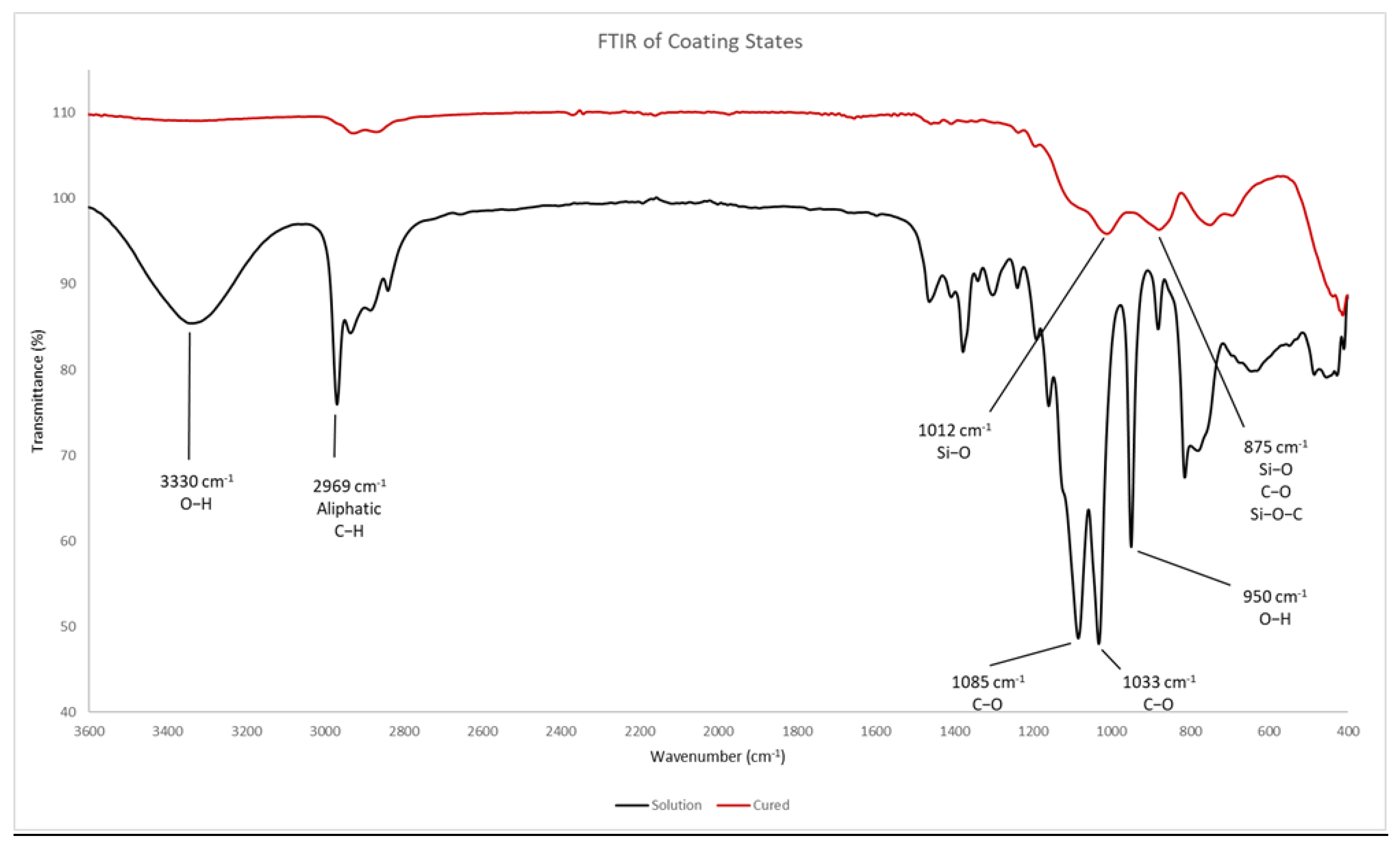
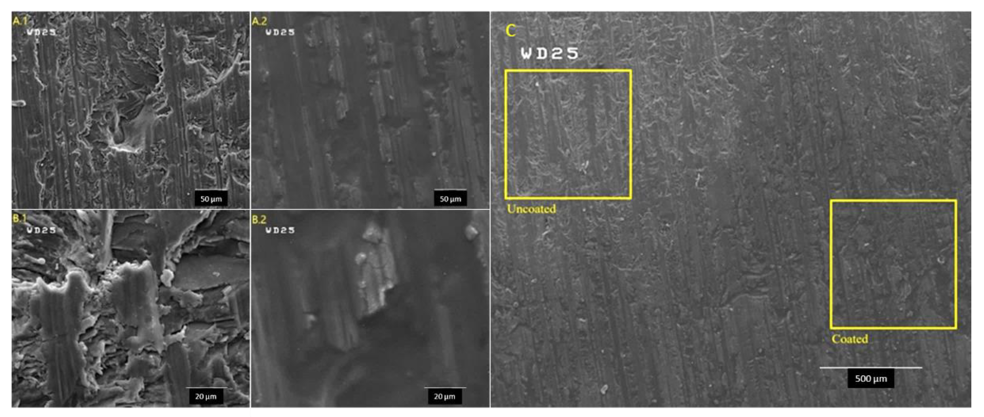
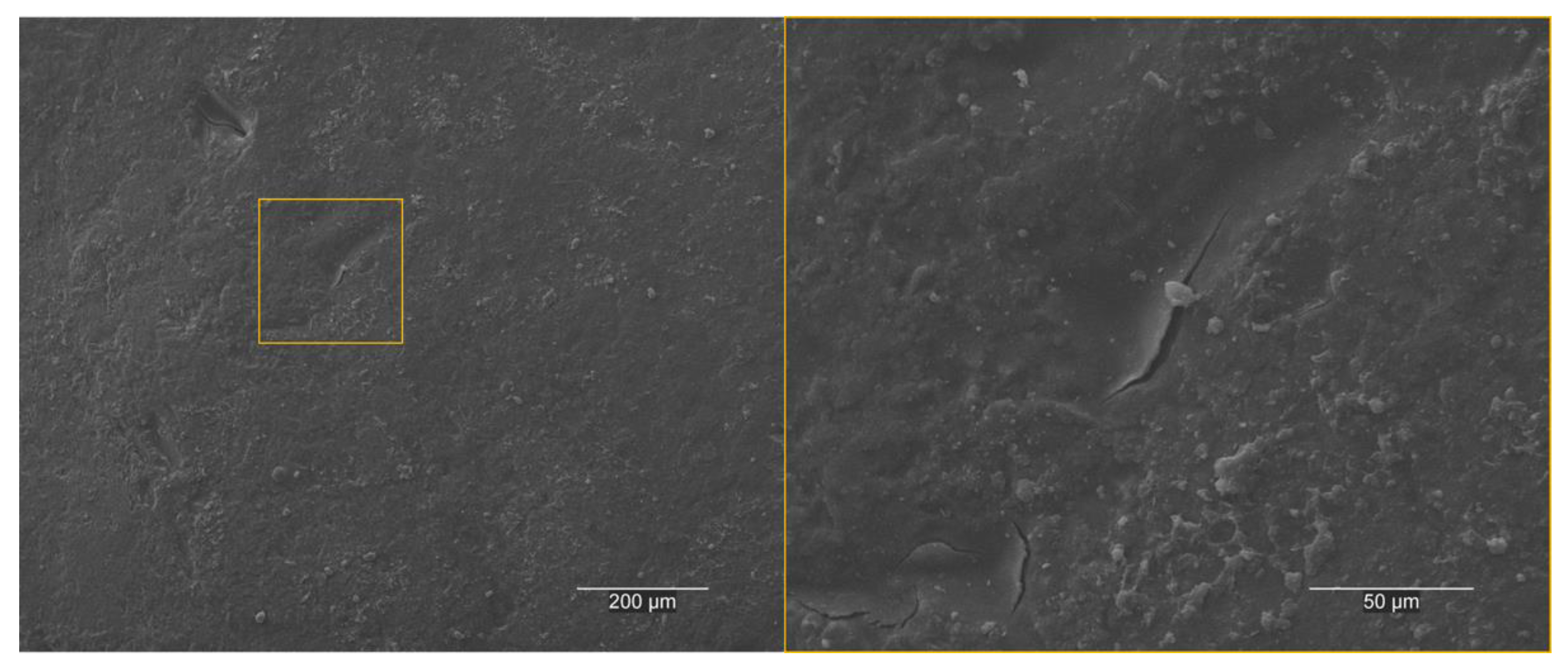
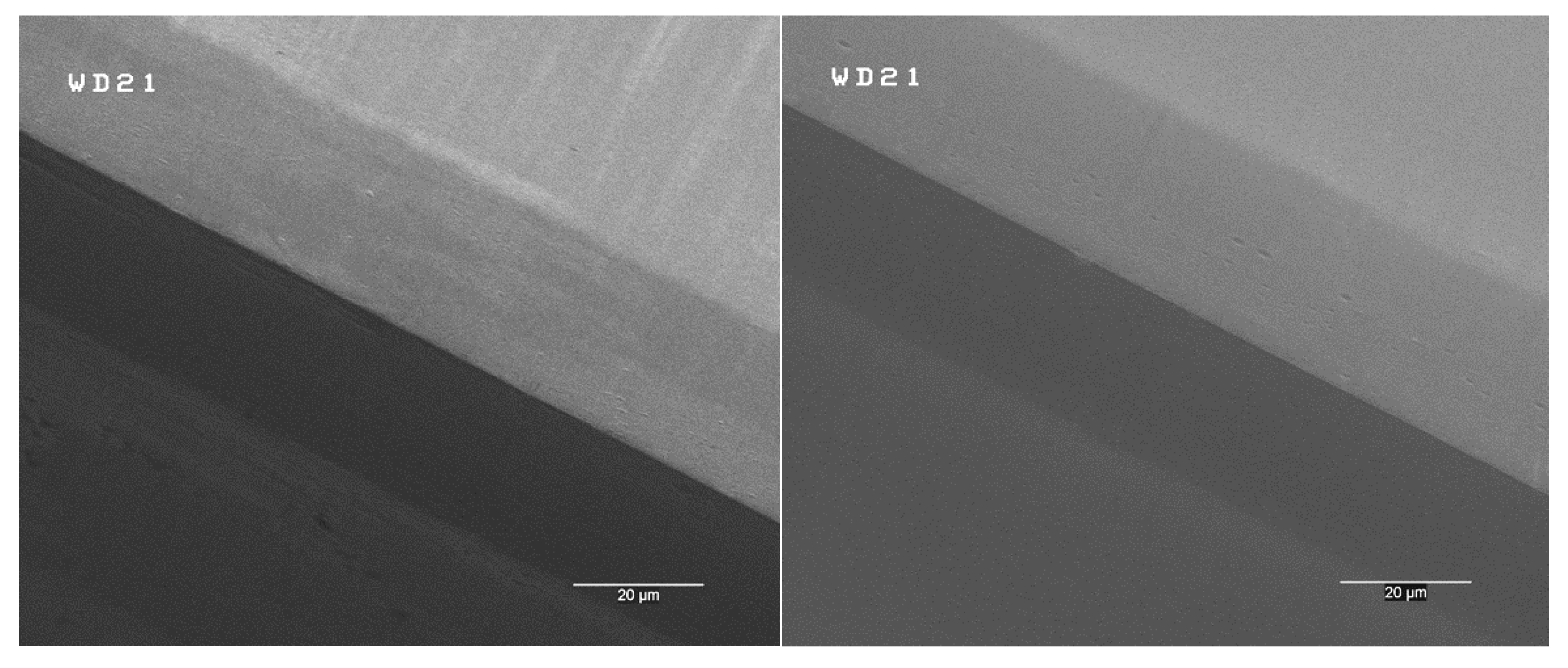
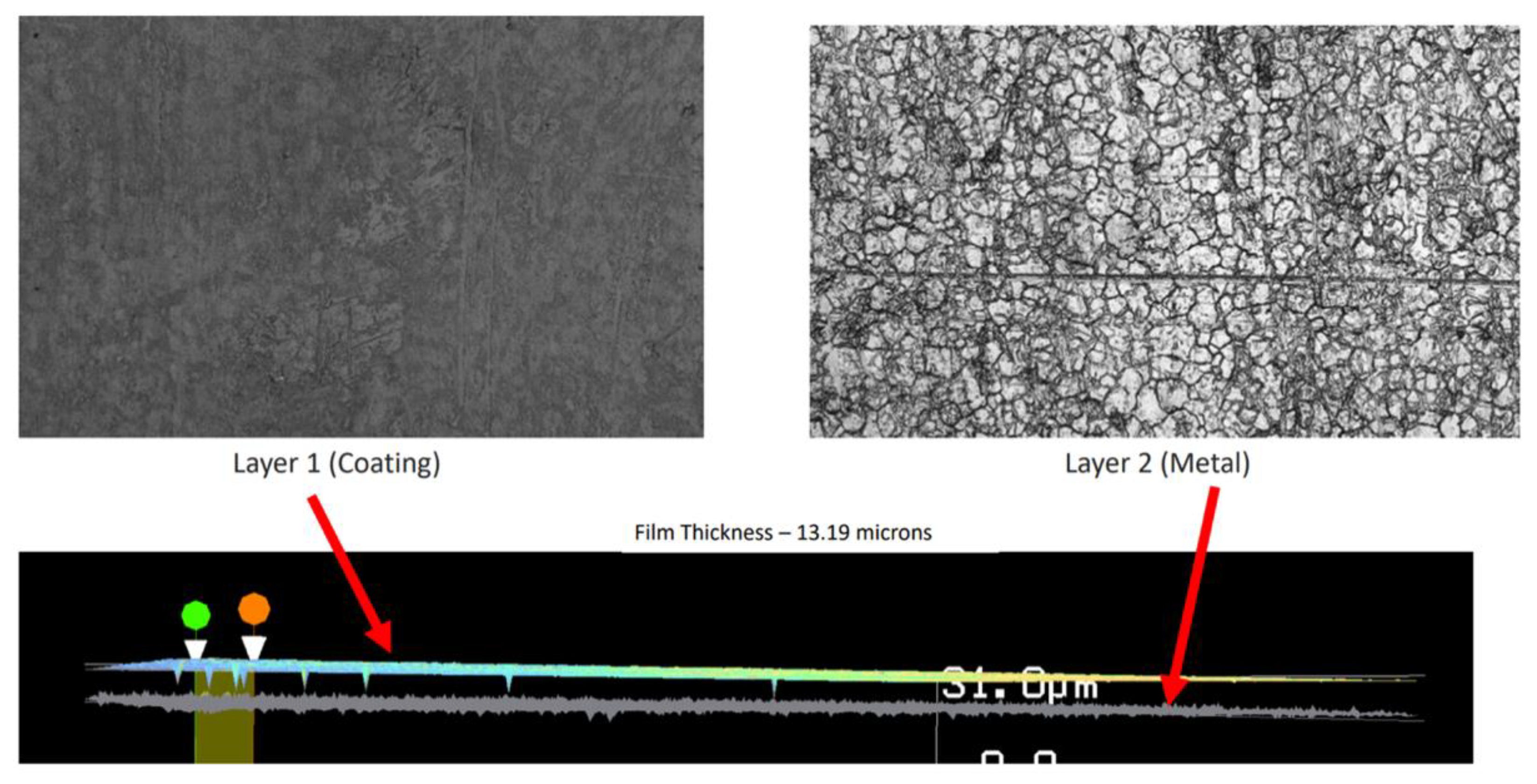
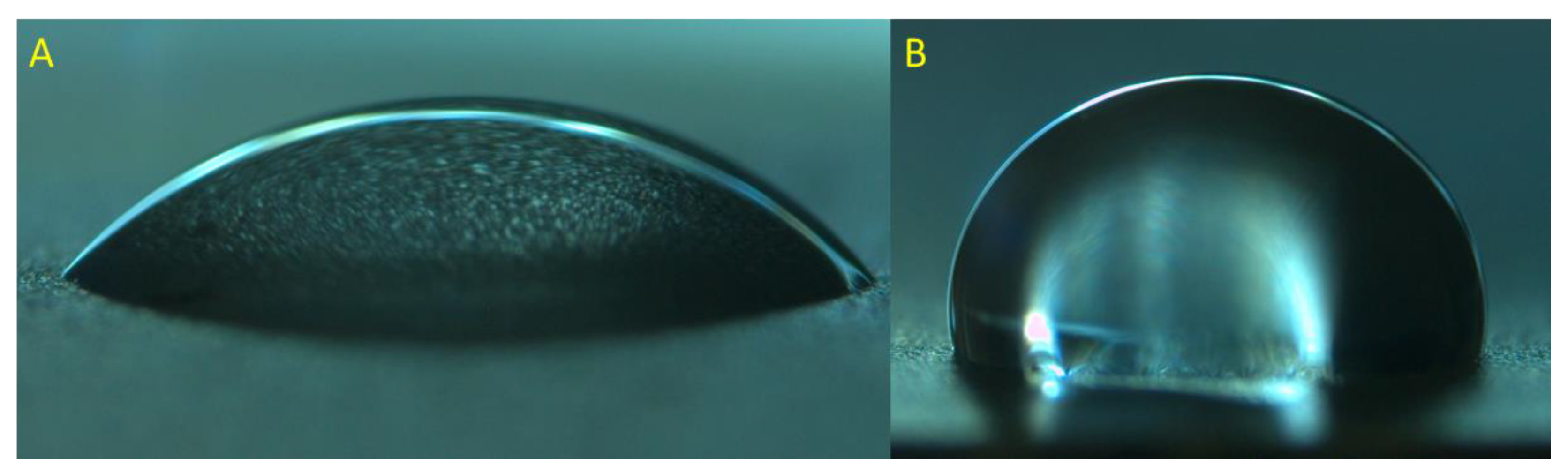
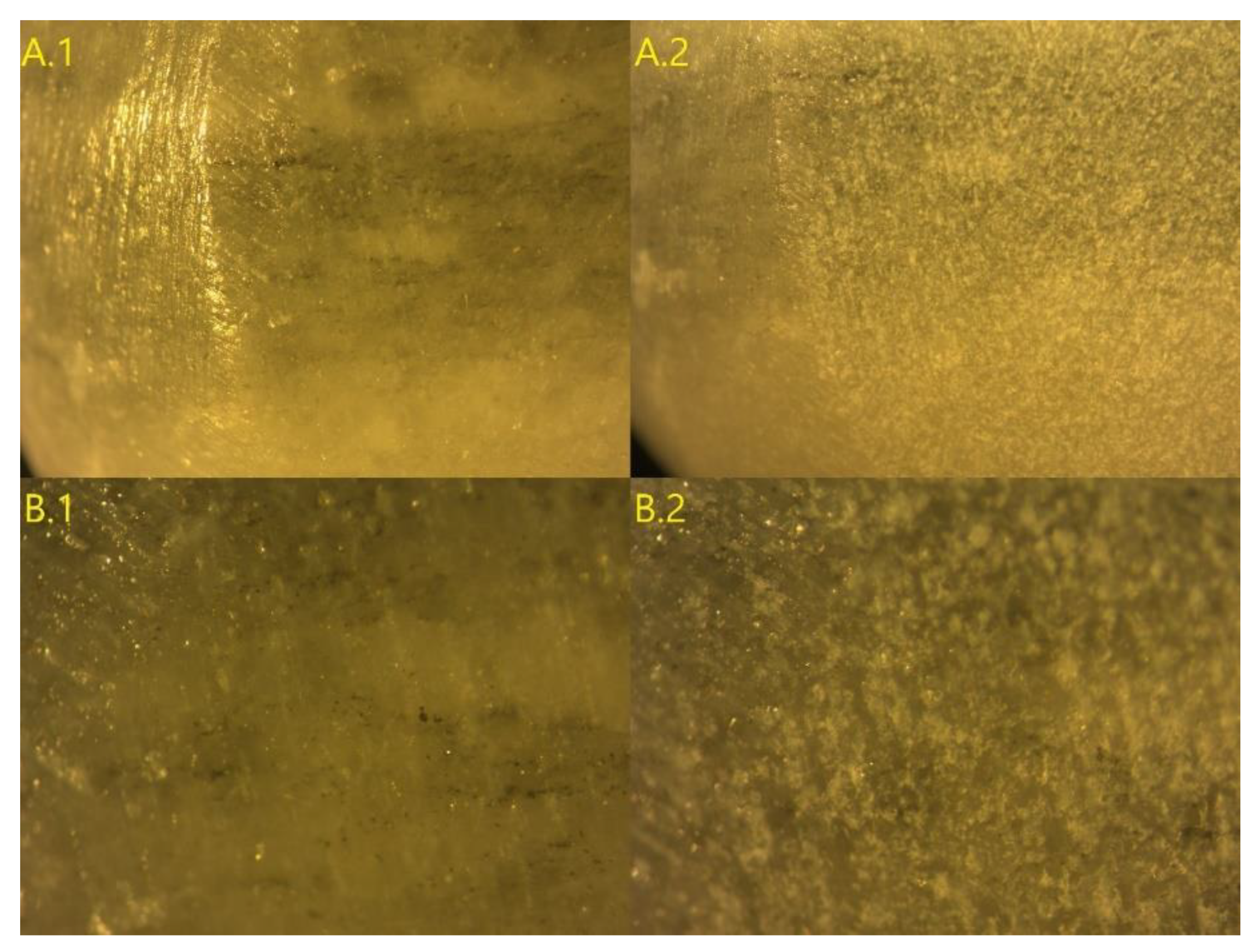
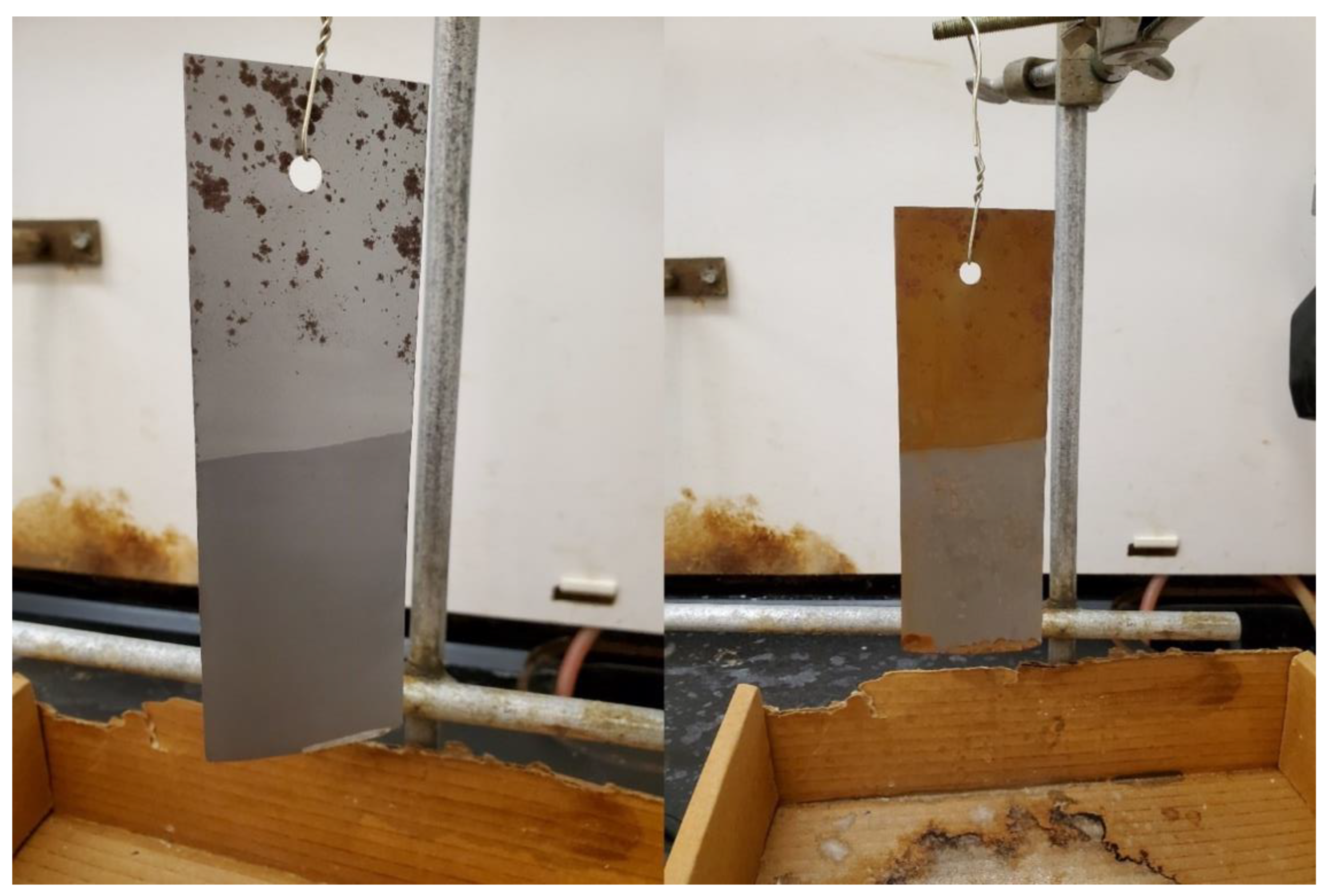
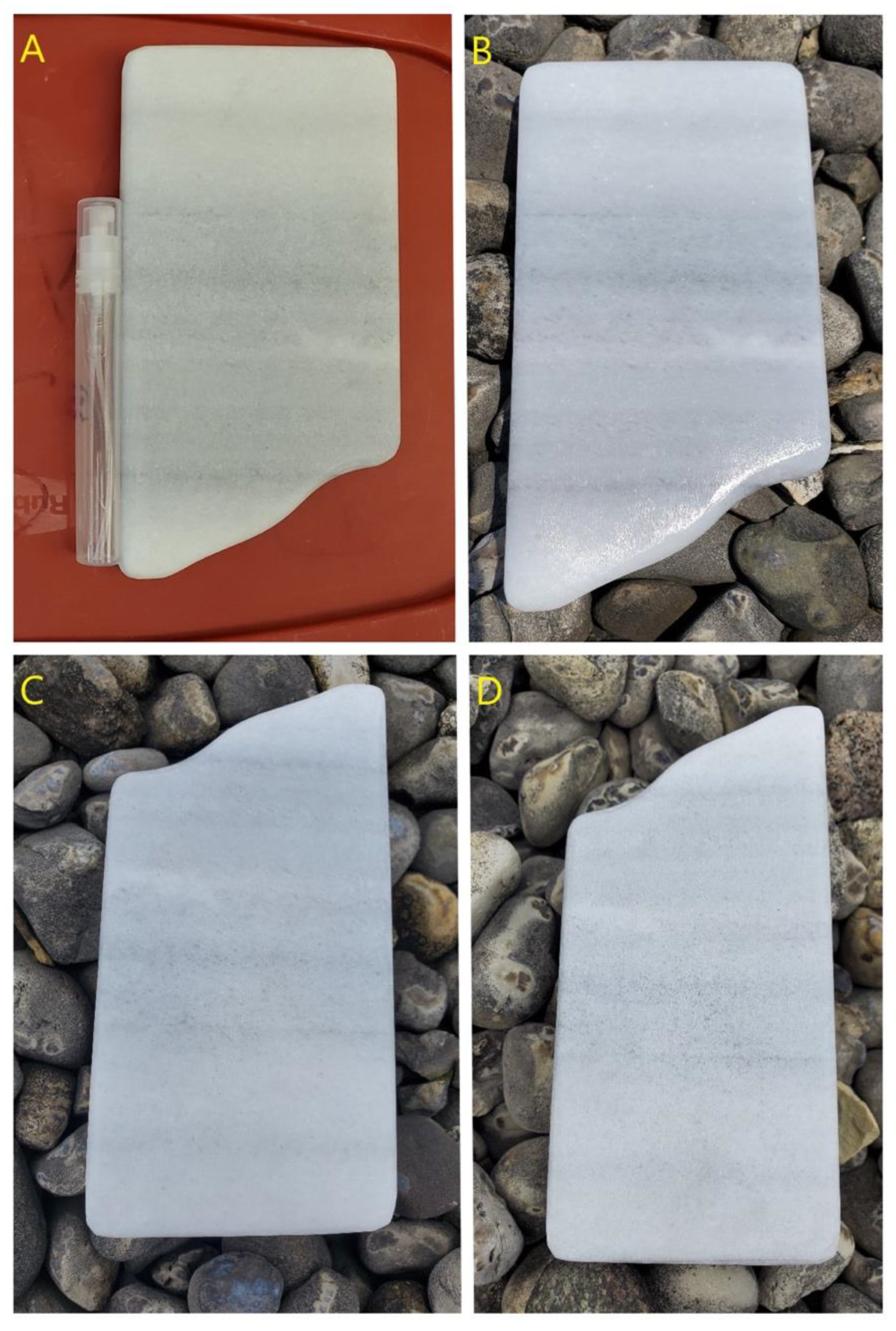
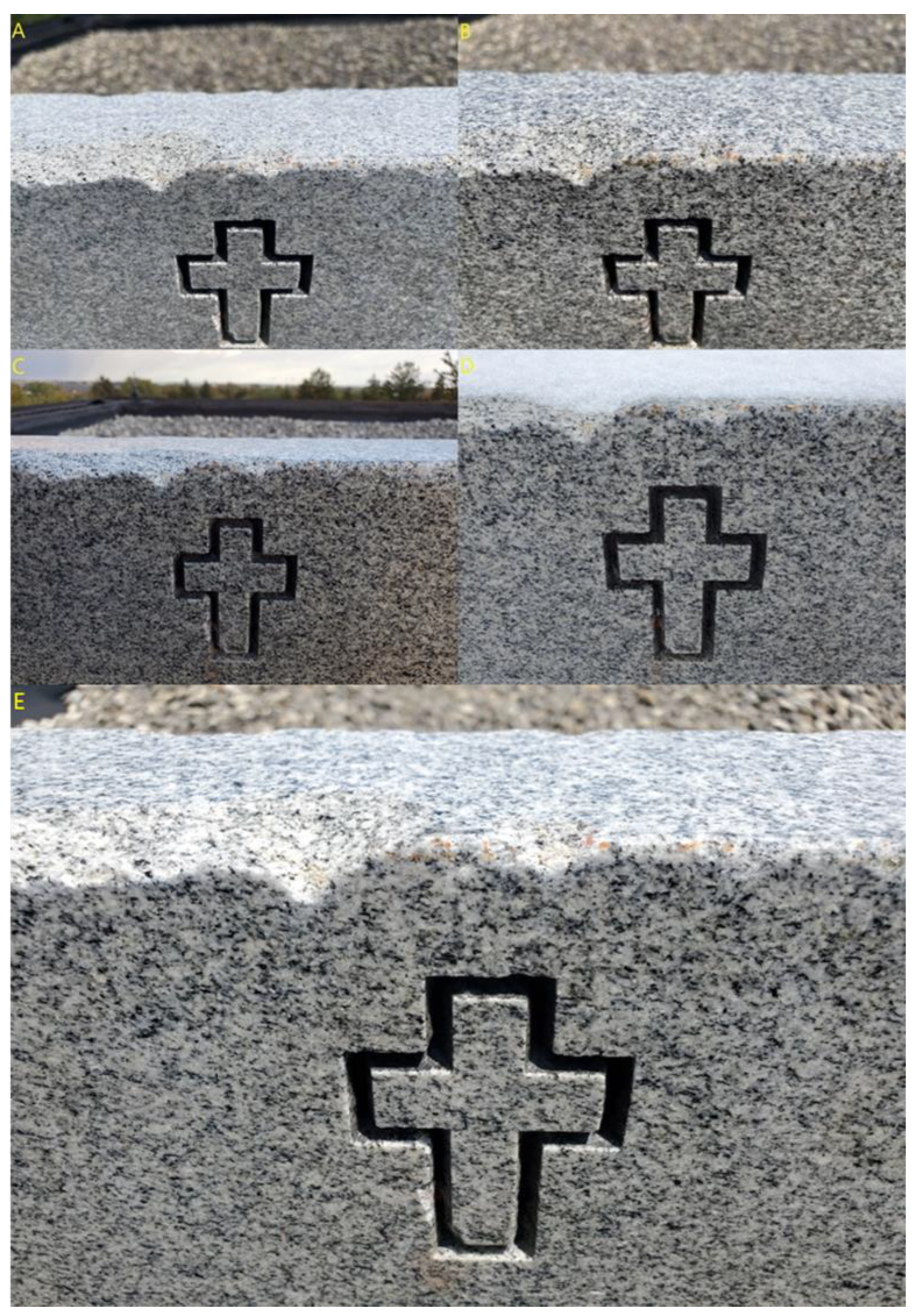
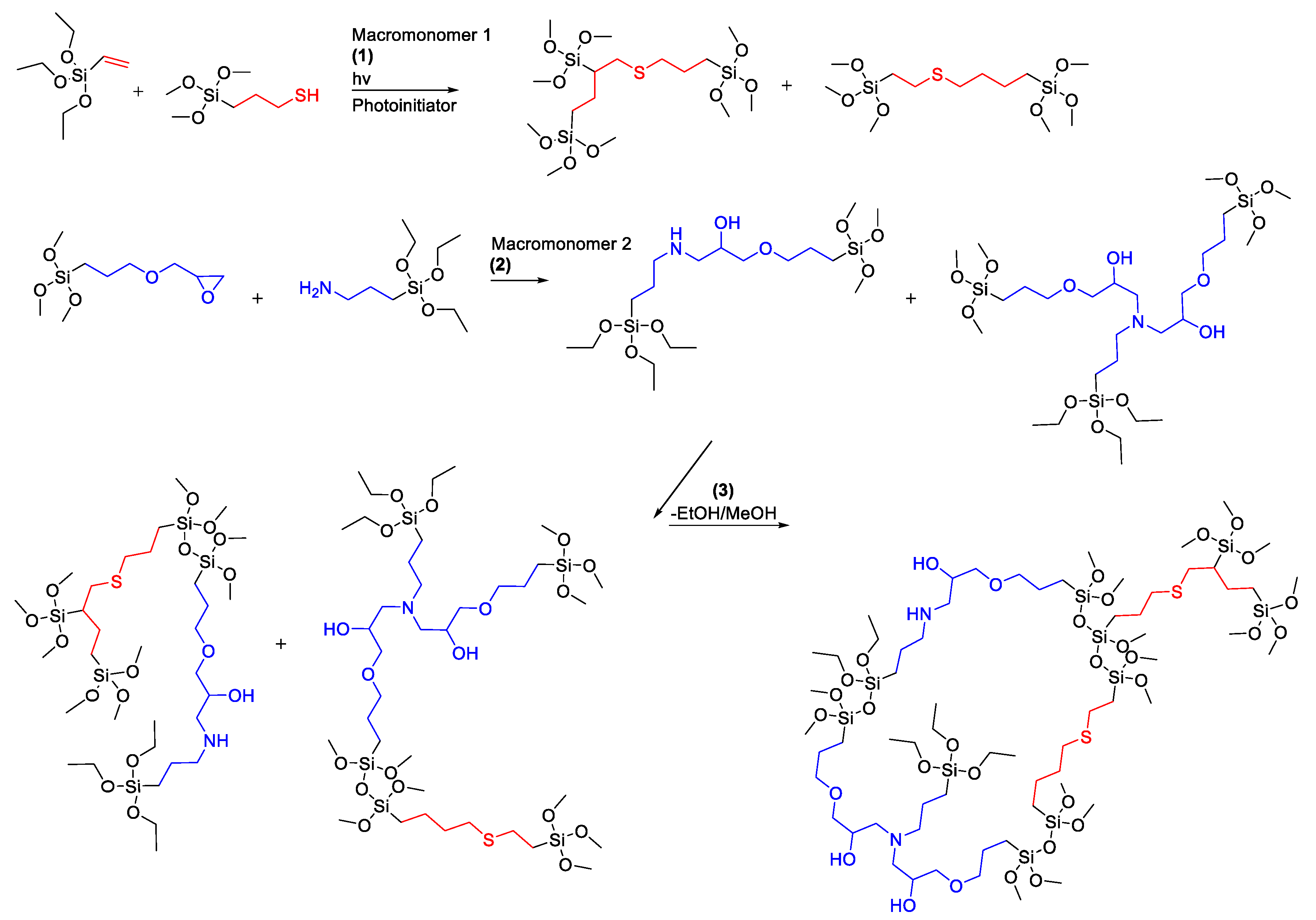
Table 1.
Ranges explored and included in the final set of working formulations. Minimum and maximum volume percentages are given. Omnirad 819 and diphenyliodonium hexafluorophosphate are solids and were calculated by % m/V.
Table 1.
Ranges explored and included in the final set of working formulations. Minimum and maximum volume percentages are given. Omnirad 819 and diphenyliodonium hexafluorophosphate are solids and were calculated by % m/V.
| Reagent Volume Percentages | Min | Max |
|---|---|---|
| 3-Glycidyloxypropyltrimethoxysilane | 7 | 30 |
| 3-Aminopropyltriethoxysilane | 6 | 30 |
| Triethoxy(1H,1H,2H,2H-nonafluorohexyl) silane | 0 | 12 |
| (Tridecafluoro-1,1,2,2-tetrahydrooctyl)triethoxysilane | 0 | 10 |
| (3-Mercaptopropyl)-trimethoxysilane | 0 | 18 |
| Omnirad 819 | 0.2 | 1 |
| Vinyltriethoxysilane | 0 | 18 |
| 2,4,6,8-Tetramethyl, 2,4,6,8-tetravinylcyclotetrasiloxane | 0 | 4 |
| 1,3-Divinyltetramethyldisiloxane | 0 | 5 |
| Vinyl Terminated Silsesquioxanes (mixed cages) | 0 | 2 |
| D4 Octamethylcyclotetrasiloxane | 0 | 10 |
| Methyltriethoxysilane | 0 | 2 |
| 1,2-Bis(triethoxysilyl)ethane | 0 | 7 |
| Tetrabutylammonium fluoride, 1 M in THF | 0 | 2 |
| Diphenyliodonium hexafluorophosphate | 0 | 8 |
| H2O | 0 | 2 |
| Poly(ethylene glycol) 400 | 0 | 2 |
| Glacial Acetic Acid | 0 | 2 |
| Methanol | 0 | 70 |
| Ethanol | 0 | 70 |
| Isopropanol | 0 | 70 |
| 1-Butanol | 0 | 50 |
Table 2.
The thirteen coating formulas resulting in the development of the final systems. All amounts are given as v/V%’s with the exception of Omnirad 819 and diphenyliodonium hexafluorophosphate which are given as m/V%’s.
Table 2.
The thirteen coating formulas resulting in the development of the final systems. All amounts are given as v/V%’s with the exception of Omnirad 819 and diphenyliodonium hexafluorophosphate which are given as m/V%’s.
| Reagent %/Formula No. | 1 | 2 | 3 | 4 | 5 | 6 | 7 | 8 | 9 | 10 | 11 | 12 | 13 |
|---|---|---|---|---|---|---|---|---|---|---|---|---|---|
| 3-Glycidyloxypropyl-trimethoxysilane | 28.0 | 13.8 | 13.8 | 13.8 | 13.7 | 14.1 | 12.7 | 13.3 | 13.7 | 13.7 | 8.2 | 13.7 | 13.6 |
| 3-Aminopropyl-triethoxysilane | 28.0 | 12.4 | 12.3 | 12.3 | 12.3 | 12.7 | 11.3 | 11.9 | 12.3 | 12.3 | 7.5 | 12.3 | 12.3 |
| Triethoxy(1H,1H,2H,2H-nonafluorohexyl) silane | 5.5 | 2.8 | 2.7 | 2.7 | 2.7 | - | 10.5 | 2.6 | 2.7 | 2.7 | 1.6 | - | - |
| (Tridecafluoro-1,1,2,2-tetrahydrooctyl)tri-ethoxysilane | - | - | - | - | - | - | - | - | - | - | - | 2.8 | 2.8 |
| (3-Mercaptopropyl)-trimethoxysilane | 9.0 | 4.8 | 4.9 | 4.9 | 4.9 | 5.0 | 4.5 | 4.7 | 4.9 | 4.9 | 2.9 | 5.0 | 5.0 |
| Vinyltriethoxysilane | 9.0 | 5.6 | 5.6 | 5.6 | 5.6 | 5.7 | 5.1 | 5.4 | 5.6 | 5.6 | 3.3 | 5.6 | 5.5 |
| Omnirad 819 | 0.5 | 0.3 | 0.6 | 0.4 | 0.7 | 0.7 | 0.5 | 0.5 | 0.5 | 0.6 | 0.3 | 0.5 | 0.8 |
| D4 Octamethylcyclo-tetrasiloxane | 8.0 | - | - | - | - | - | - | - | - | - | - | - | - |
| Diphenyliodonium hexafluorophosphate | - | - | - | - | - | - | - | 3.4 | 0.1 | 0.2 | 0.1 | 0.2 | 0.3 |
| Methanol | 12.0 | 60.3 | 60.2 | 60.3 | - | 61.8 | 55.4 | 58.2 | 60.1 | - | 36.1 | 18.1 | 18.1 |
| Ethanol | - | - | - | - | 60.1 | - | - | - | - | - | - | - | - |
| Isopropanol | - | - | - | - | - | - | - | - | - | 60.1 | 40.1 | 41.8 | - |
| 1-Butanol | - | - | - | - | - | - | - | - | - | - | - | - | 41.7 |
Table 3.
Substrates and applications investigated for each of the formulas used. Each material is noted what application methods were used in parenthesis as sprayed (S), dipped (D), and wiped (W). Not all samples or methods listed were used in analysis or measurements.
Table 3.
Substrates and applications investigated for each of the formulas used. Each material is noted what application methods were used in parenthesis as sprayed (S), dipped (D), and wiped (W). Not all samples or methods listed were used in analysis or measurements.
| Formula No. | Application Substrates and Methods | ||||||
|---|---|---|---|---|---|---|---|
| 1 | Marble (S) | Glass (S) | - | - | - | - | - |
| 2 | Marble (S) | Glass (S) | - | - | - | - | - |
| 3 | Marble (S) | - | - | - | - | - | - |
| 4 | Marble (S) | - | - | - | - | - | - |
| 5 | Marble (S) | - | - | - | - | - | - |
| 6 | Marble (S) | Glass (S) | - | - | - | - | - |
| 7 | Marble (S) | Glass (S) | - | - | - | - | - |
| 8 | Marble (S) | Glass (S) | - | - | - | - | - |
| 9 | Marble (S) | Glass (S) | - | - | - | - | - |
| 10 | Marble (S) | Glass (S) | - | - | - | - | - |
| 11 | Marble (S) | Glass (S, D, W) | Granite (S) | Brick (S) | Nitrile (S, W) | Steel (S) | - |
| 12 | Marble (S) | Glass (S, D, W) | Granite (S) | Brick (S) | Nitrile (S, W) | Steel (S, D, W) | Wood (D) |
| 13 | - | Glass (S, D) | - | - | - | - | - |
Table 4.
Average static contact angles of samples on different surfaces over the course of development. Selected samples are part of the progression of the model systems development and were used in the other analysis methods. Standard deviations are given in parenthesis.
Table 4.
Average static contact angles of samples on different surfaces over the course of development. Selected samples are part of the progression of the model systems development and were used in the other analysis methods. Standard deviations are given in parenthesis.
| Formula No. | Average Contact Angle on Marble | Average Contact Angle on Glass | Average Contact Angle on Brick | Average Contact Angle on Steel | Average Contact Angle on Wood |
|---|---|---|---|---|---|
| Uncoated | 73.3° (±0.4) | 45.8° (±0.5) | Absorbed | 58.8° (±5.3) | Absorbed |
| 1 | 94.9° (±0.8) | 101.4° (±0.2) | - | - | - |
| 2 | - | 105° (±1.2) | - | - | - |
| 3 | 92.2° (±0.6) | - | - | - | - |
| 4 | 97° (±1.1) | - | - | - | - |
| 5 | 99° (±1.1) | - | - | - | - |
| 6 | 93° (±1.6) | - | - | - | - |
| 7 | 101.6° (±0.2) | - | - | - | - |
| 8 | 96° (±1.1) | - | - | - | - |
| 9 | 100.8° (±0.4) | - | - | - | - |
| 10 | 96.9° (±0.5) | - | - | - | - |
| 11 | 100.1° (±0.1) | 105.5° (±0.4) | 104° (±6.2) | - | - |
| 12 | 101.5° (±0.1) | 101.8° (±0.6) | 129.1° (±0.2) | 103.7° (±0.4) | 131.7° (±0.4) |
| 13 | - | 104.2° (±0.4) | - | - | - |
Publisher’s Note: MDPI stays neutral with regard to jurisdictional claims in published maps and institutional affiliations. |
© 2022 by the authors. Licensee MDPI, Basel, Switzerland. This article is an open access article distributed under the terms and conditions of the Creative Commons Attribution (CC BY) license (https://creativecommons.org/licenses/by/4.0/).
Share and Cite
MDPI and ACS Style
Sims, C.B.; Lenora, C.U.; Furgal, J.C. Hybrid Tri-Cure Organo-Silicon Coatings for Monument Preservation. Coatings 2022, 12, 1098. https://doi.org/10.3390/coatings12081098
AMA Style
Sims CB, Lenora CU, Furgal JC. Hybrid Tri-Cure Organo-Silicon Coatings for Monument Preservation. Coatings. 2022; 12(8):1098. https://doi.org/10.3390/coatings12081098
Chicago/Turabian StyleSims, Cory B., Chamika U. Lenora, and Joseph C. Furgal. 2022. "Hybrid Tri-Cure Organo-Silicon Coatings for Monument Preservation" Coatings 12, no. 8: 1098. https://doi.org/10.3390/coatings12081098
Note that from the first issue of 2016, this journal uses article numbers instead of page numbers. See further details here.