Preparation of Water Suspensions of Nanocalcite for Cultural Heritage Applications

 ,
, 
 , ,
, ,
Abstract
:
1. Introduction
2. Materials and Methods
2.1. Materials
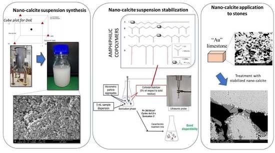
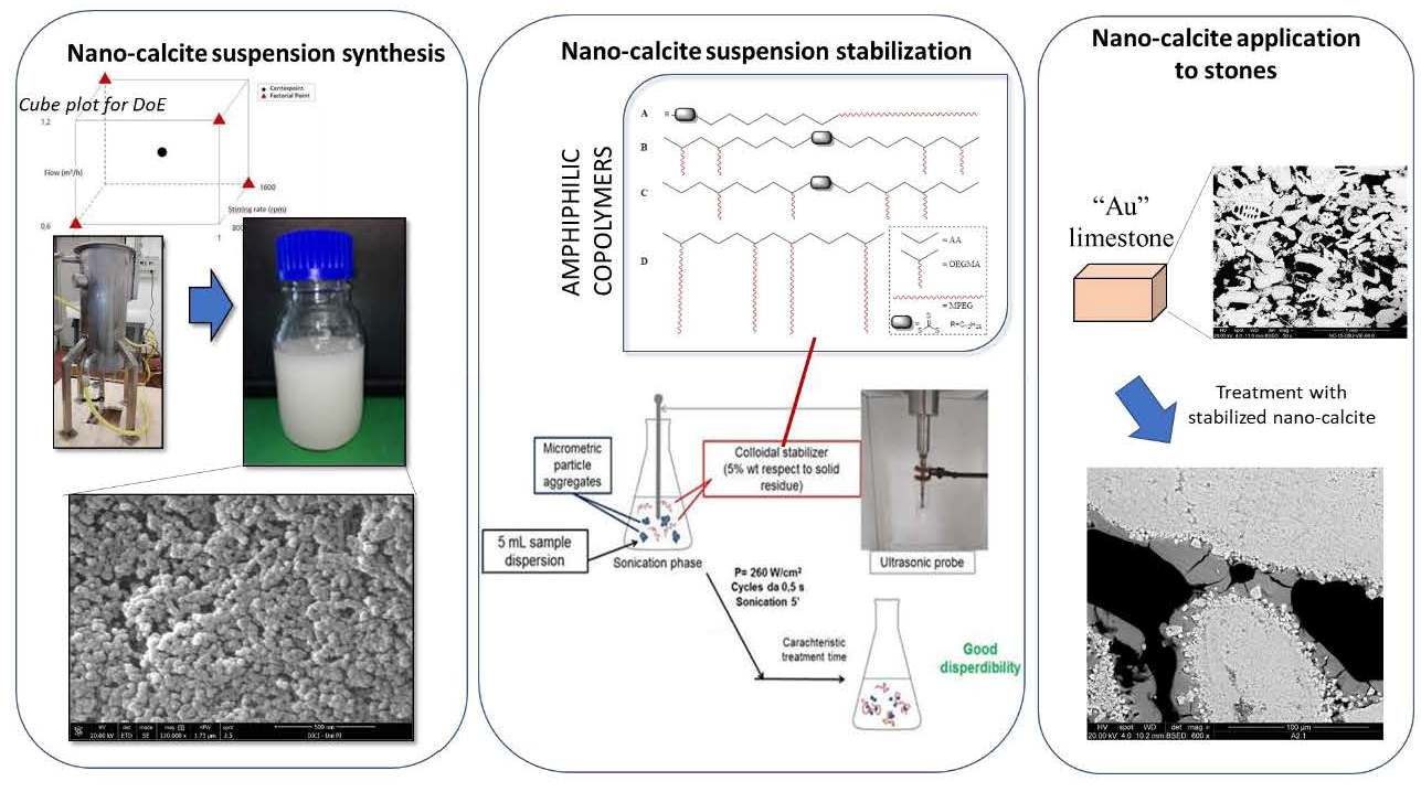
2.2. Syntheses
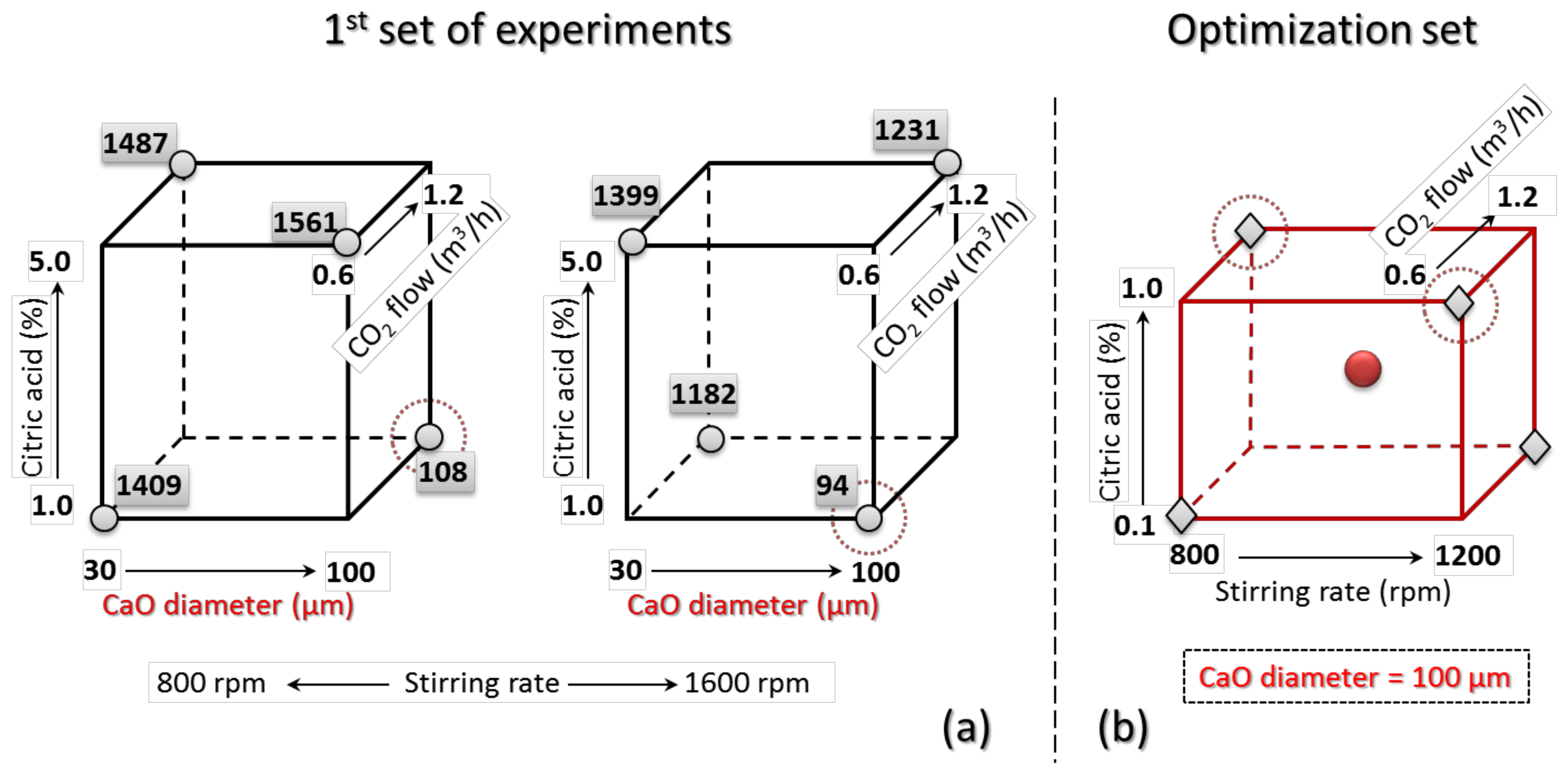
2.3. Experimental Design
2.4. Characterization of Nanostructured Suspensions
2.5. Colloidal Stabilizers of the Nanocalcite Suspensions
2.6. Preliminary Test Treatments on Porous Substrates
2.7. Stone Sample Treatment and Characterization
3. Results
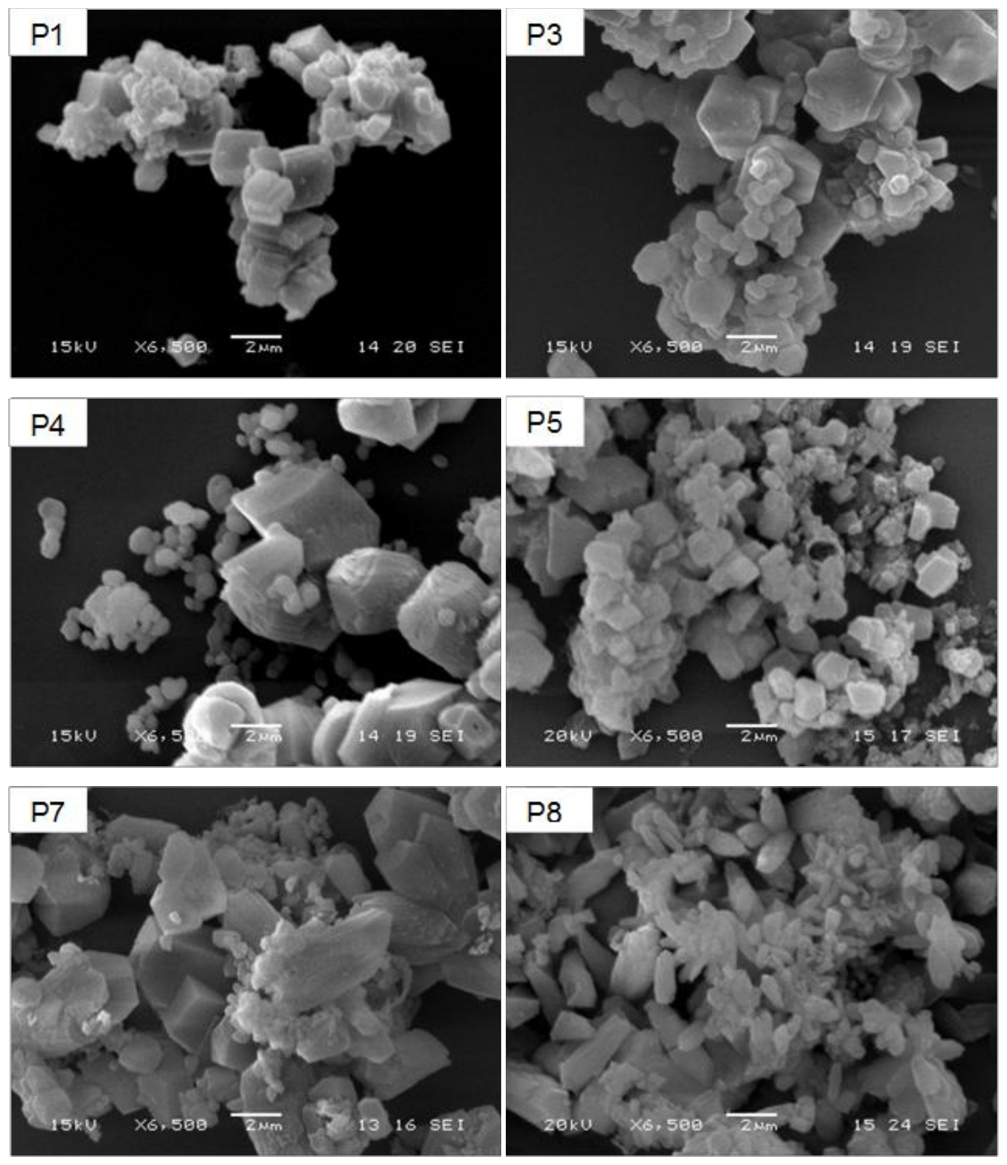
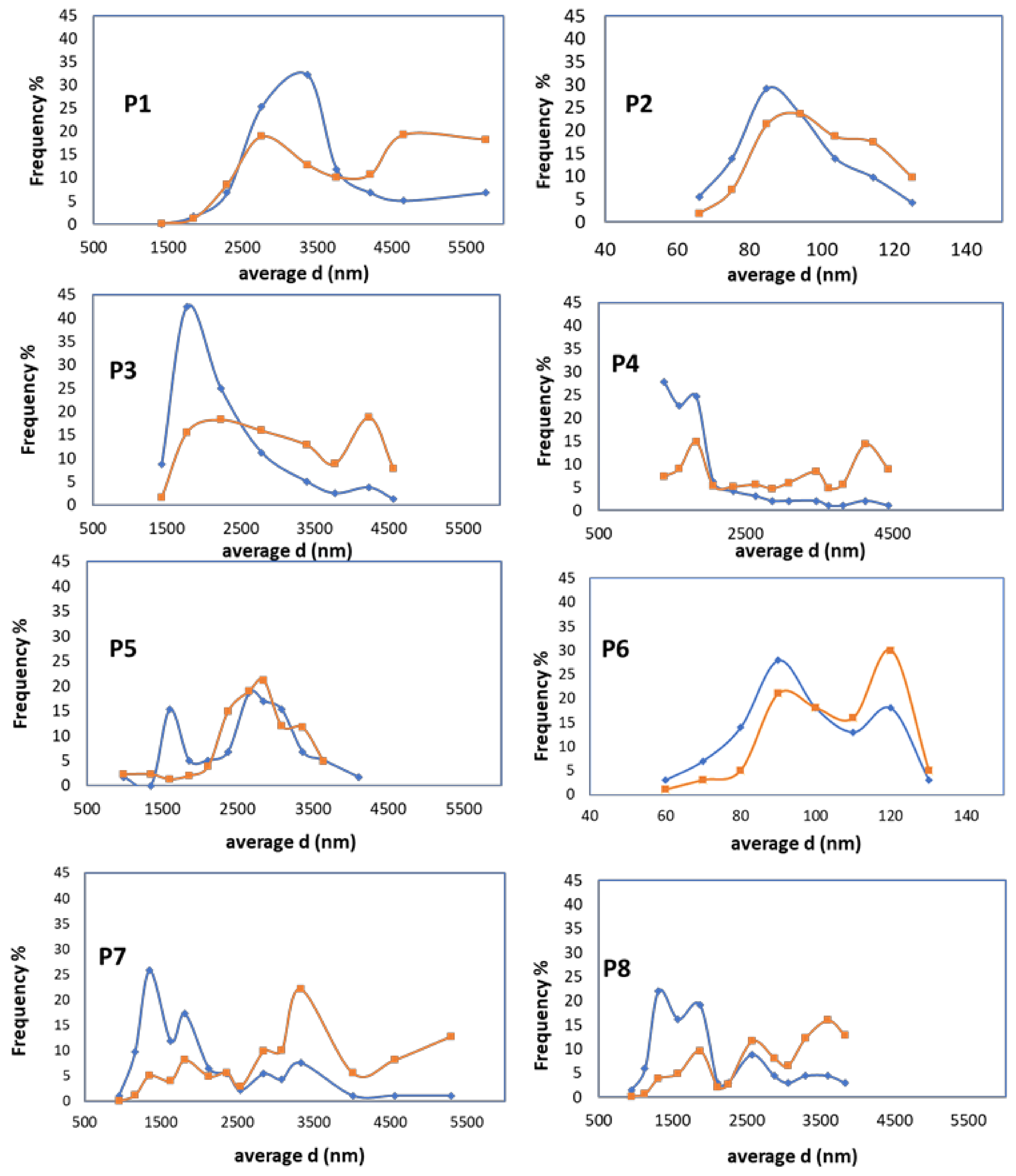
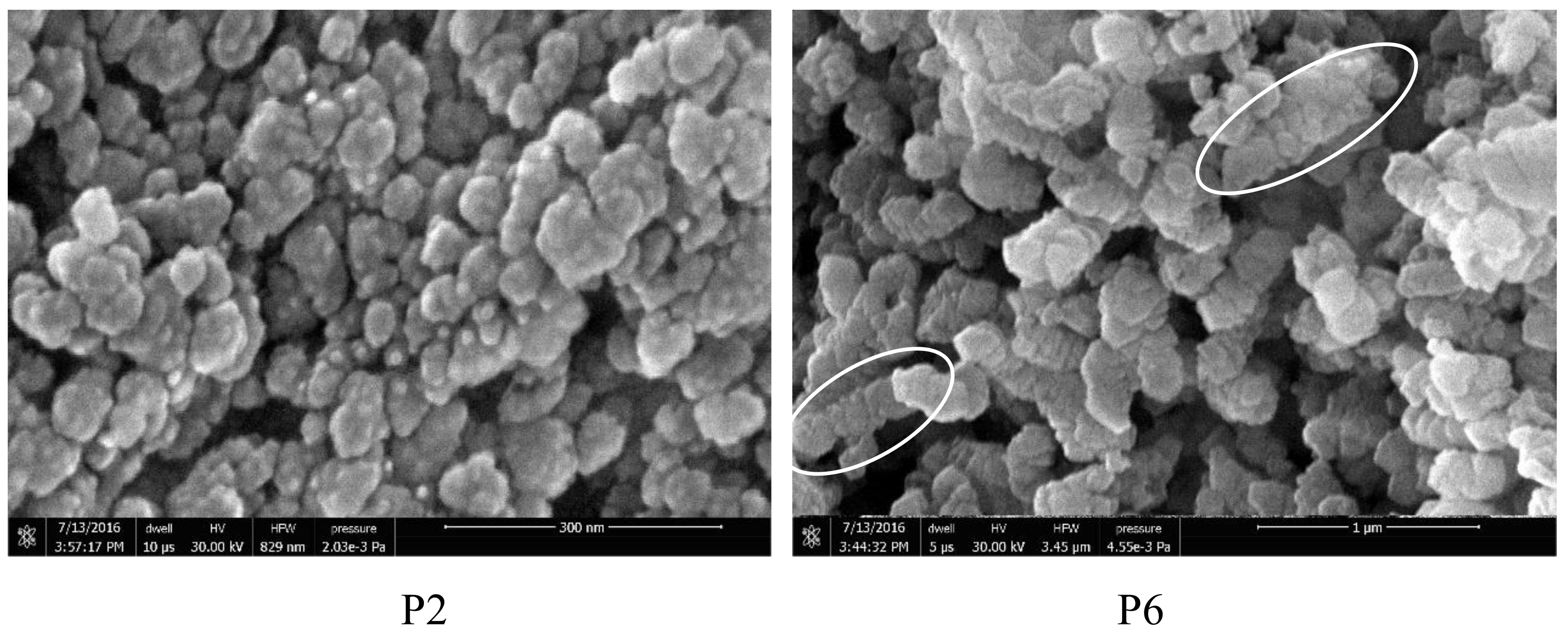
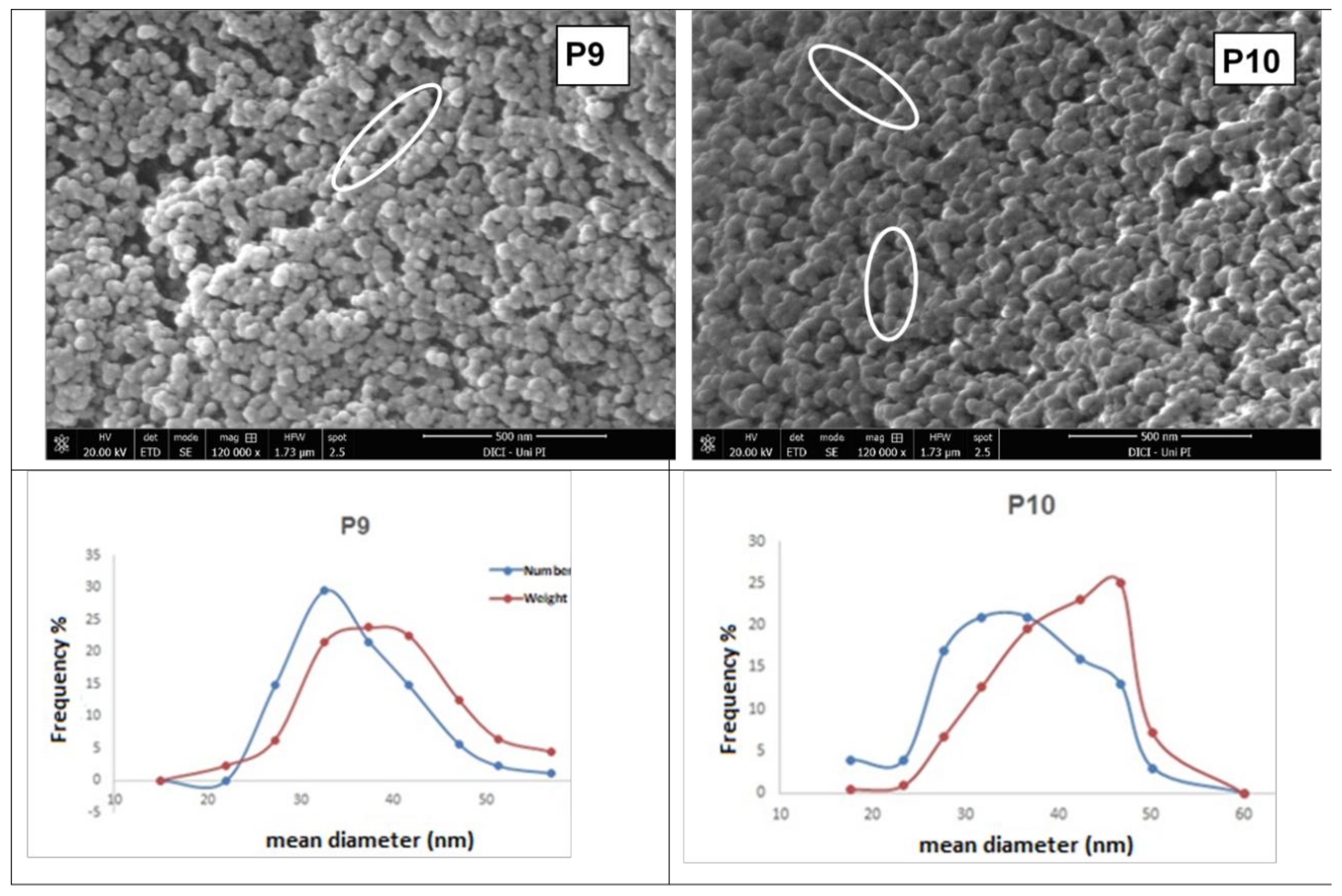
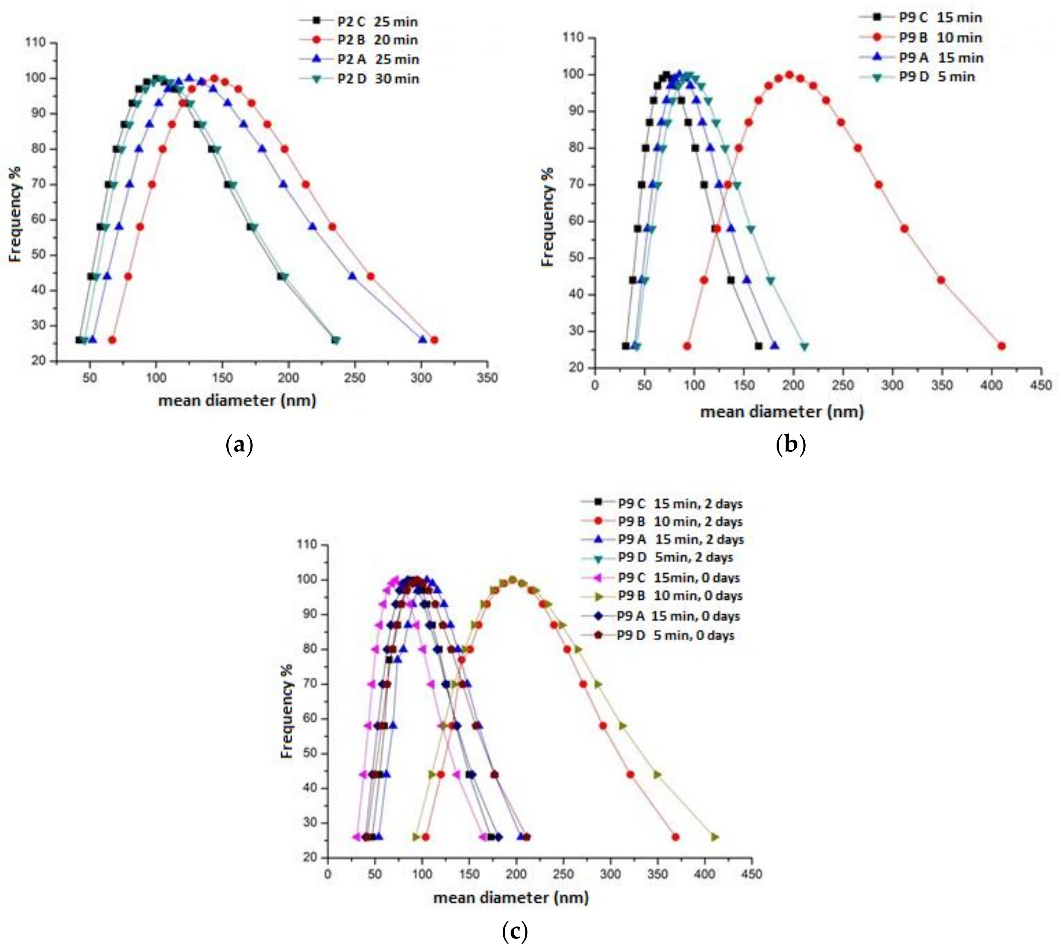
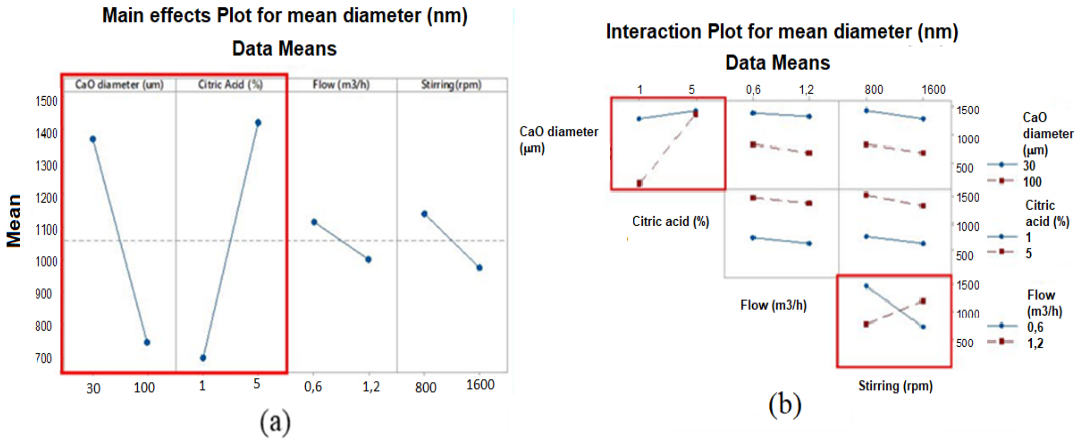
3.1. Influence of Process Parameters on CCNP Size and Morphology
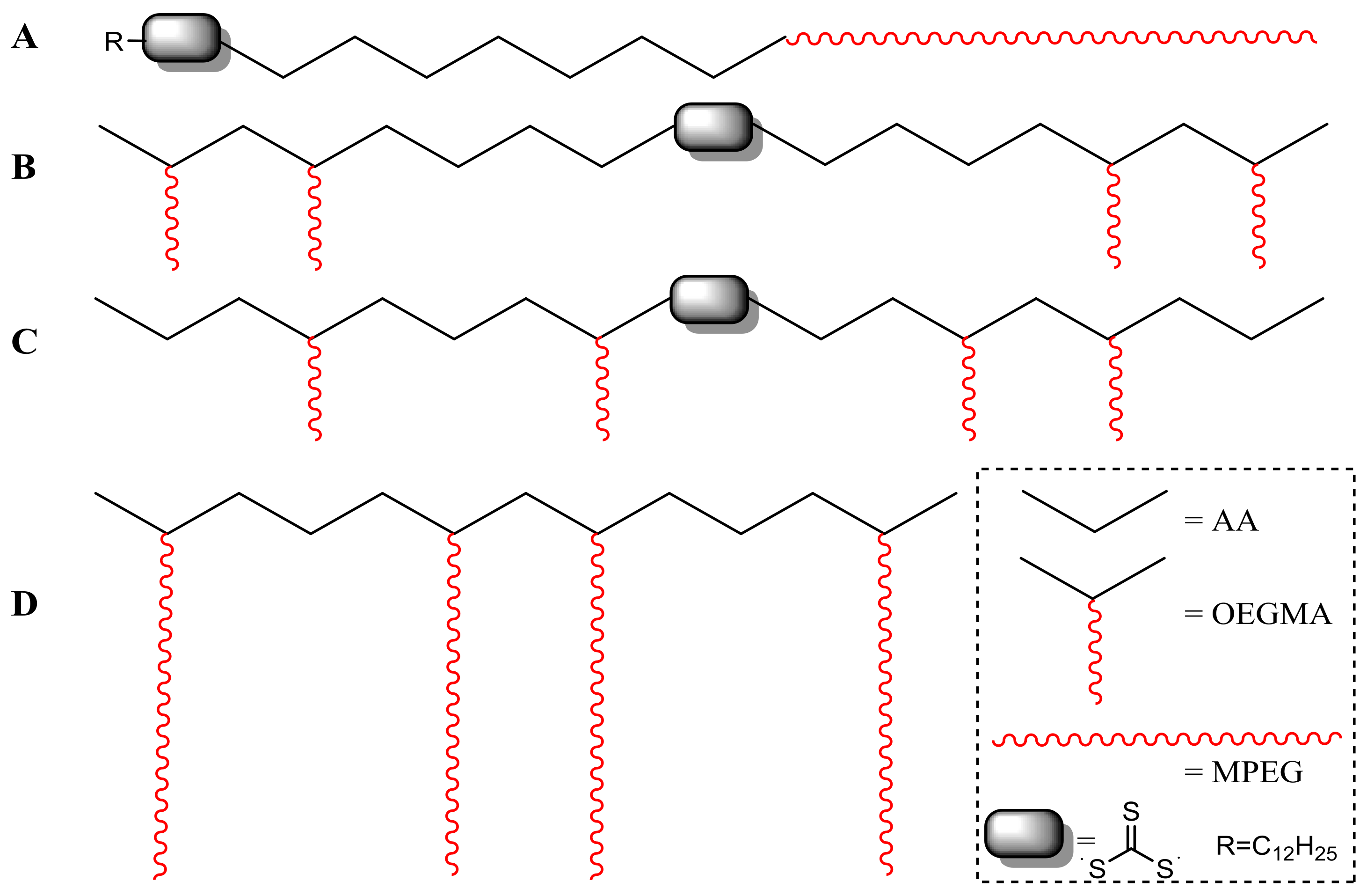
3.2. Stabilization of the Aqueous Nanocalcite Dispersions by Adsorption of Amphiphilic or Double-Hydrophilic Copolymers
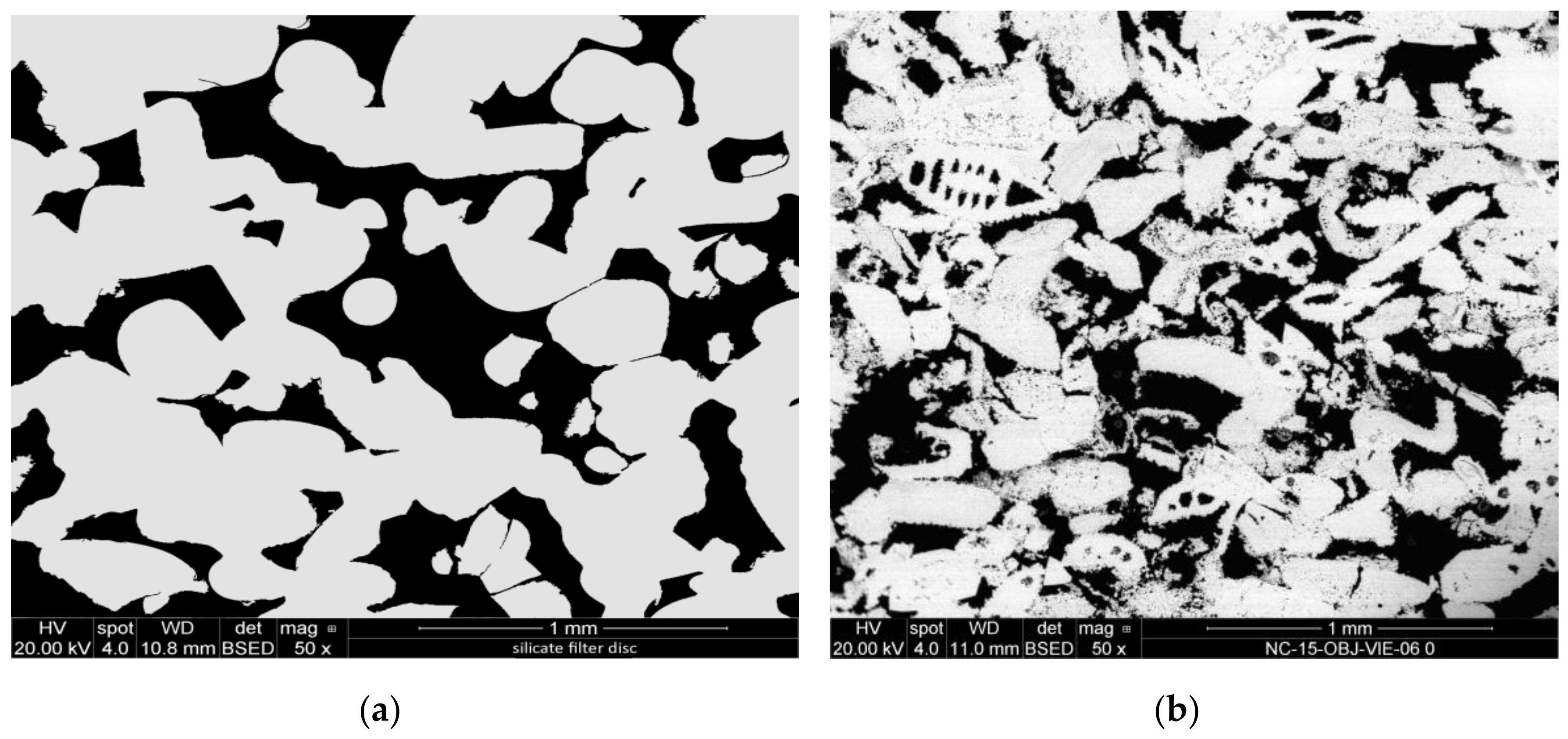
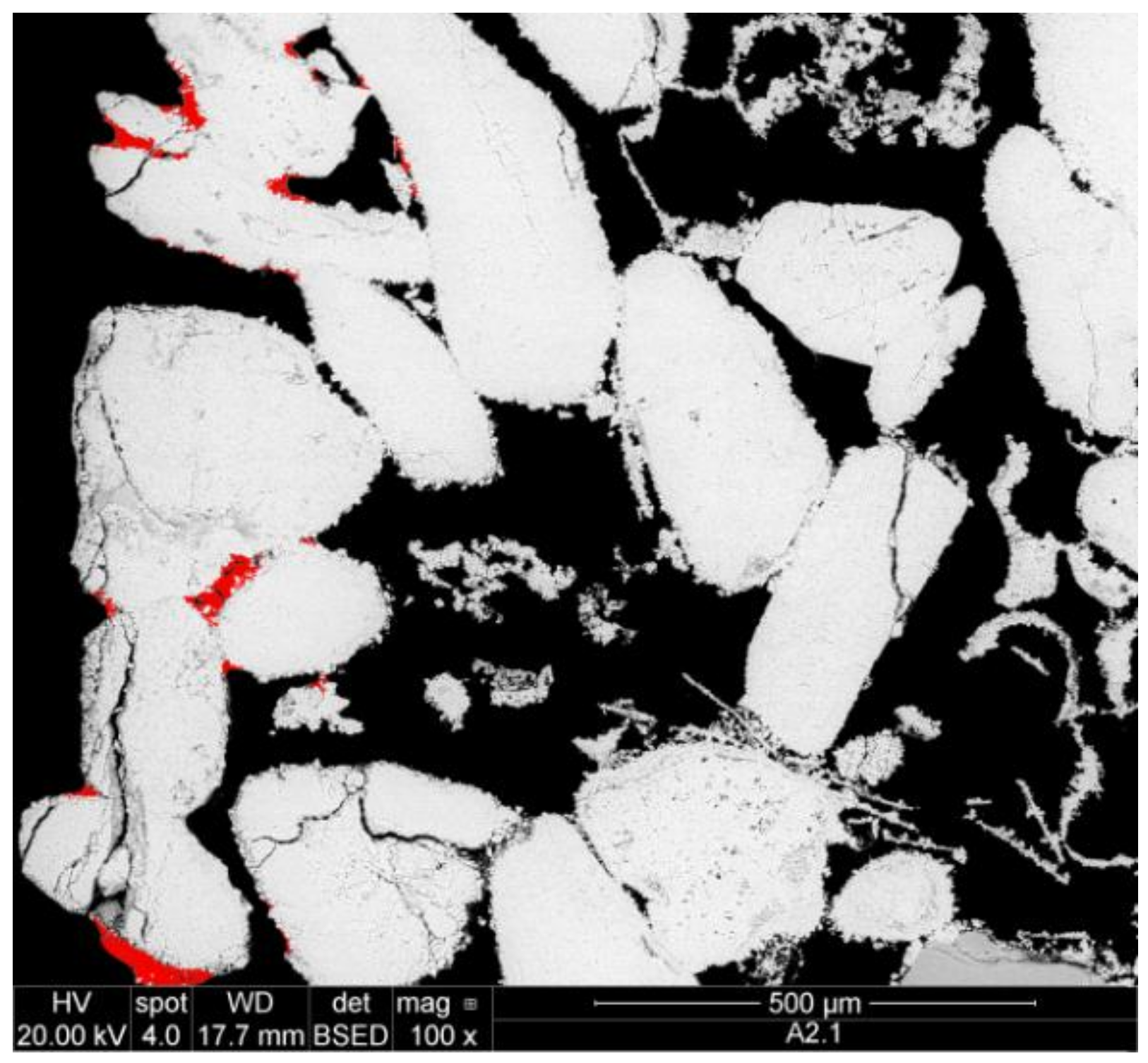
3.3. Pickup of Nanoparticle Dispersions by Porous Substrates and Penetration Depth
4. Conclusions
Acknowledgments
Author Contributions
Conflicts of Interest
References
- Mosquera, M.J.; de los Santos, D.M.; Montes, A.; Valdez-Castro, L. New nanomaterials for consolidating stones. Langmuir 2008, 24, 2772–2778. [Google Scholar] [CrossRef] [PubMed]
- Zarraga, R.; Cervantes, J.; Salazar-Hernandez, C.; Wheeler, G. Effect of the Addition of Hydroxyl-terminated polydimethylsiloxane to TEOS-based Stone Consolidants. J. Cult. Herit. 2009, 11, 138–144. [Google Scholar] [CrossRef]
- Zornoza-Indart, A.; Lopez-Arce, P. Silica nanoparticles (SiO2): Influence of relative humidity in stone consolidation. J. Cult. Herit. 2016, 18, 258–270. [Google Scholar] [CrossRef]
- Baldi, G.; Cioni, A.; Dami, V.; Soldi, A.; Signorini, A. Nano-Structured Glassy and Ceramic Surfaces: Development of “Active” Materials for an Innovative Approach to Building Industry. Adv. Sci. Technol. 2010, 68, 135–144. [Google Scholar] [CrossRef]
- Verganelaki, A.; Kapridaki, C.; Maravelaki-Kalaitzaki, P. Modified tetraethoxysilane with nanocalcium oxalate in one-pot synthesis for protection of building materials. Ind. Eng. Chem. Res. 2015, 54, 7195–7206. [Google Scholar] [CrossRef]
- Verganelaki, A.; Kilikoglou, V.; Karatasios, I.; Maravelaki-Kalaitzaki, P. A biomimetic approach to strengthen and protect construction materials with novel calcium-oxalate-silica nanocomposite. Constr. Build. Mater. 2014, 62, 8–17. [Google Scholar] [CrossRef]
- Sassoni, E.; Graziani, G.; Franzoni, E. An innovative phosphate-based consolidant for limestone. Part 1: Effectiveness and compatibility in comparison with ethyl silicate. Constr. Build. Mater. 2016, 102, 918–930. [Google Scholar] [CrossRef]
- Sassoni, E.; Graziani, G.; Ridolfi, G.; Bignozzi, M.C.; Franzoni, E. Thermal behavior of Carrara marble after consolidation by ammonium phosphate, ammonium oxalate and ethyl silicate. Mater. Des. 2017, 120, 345–353. [Google Scholar] [CrossRef]
- Baglioni, P.; Chelazzi, D.; Giorgi, R.; Poggi, G. Colloid and Materials Science for the conservation of cultural heritage: Cleaning, consolidation, and deacidification. Langmuir 2013, 29, 5110–5122. [Google Scholar] [CrossRef] [PubMed]
- Chelazzi, D.; Poggi, G.; Jaidar, Y.; Toccafondi, N.; Giorgi, R.; Baglioni, P. Hydroxide nanoparticles for cultural heritage: Consolidation and protection of wall paintings and carbonate materials. J. Colloid Interface Sci. 2013, 392, 42–49. [Google Scholar] [CrossRef] [PubMed]
- Bonazza, A.; Vidorni, G.; Natali, I.; Ciantelli, C.; Giosuè, C.; Tittarelli, F. Durability assessment to environmental impact of nano-structured consolidants on Carrara marble by field exposure tests. Sci. Total Environ. 2017, 575, 23–32. [Google Scholar] [CrossRef] [PubMed]
- Rodriguez-Navarro, C.; Vettori, I.; Ruiz-Agudo, E. Kinetics and mechanism of calcium hydroxide conversion into calcium alkoxides: Implications in heritage conservation using nanolimes. Langmuir 2016, 32, 5183–5194. [Google Scholar] [CrossRef] [PubMed]
- Favaro, M.; Tomasin, P.; Ossola, F.; Vigato, P.A. A novel approach to consolidation of historical limestone: The calcium alkoxides. Appl. Organomet. Chem. 2008, 22, 698–704. [Google Scholar] [CrossRef]
- Pondelak, A.; Kramar, S.; Kikelj, M.L.; Škapin, A.S. In-situ study of the consolidation of wall paintings using commercial and newly developed consolidants. J. Cult. Herit. 2017, 28, 1–8. [Google Scholar] [CrossRef]
- Min, Y.; Akbulut, M.; Kristiansen, K.; Golan, Y.; Israelachvili, J. The role of interparticle and external forces in nanoparticle assembly. Nat. Mater. 2008, 7, 527–538. [Google Scholar] [CrossRef] [PubMed]
- Sanchez Dominguez, M.; Rodriguez-abreu, C. Nanocolloids, a Meeting Point for Scientists and Technologists; Elsevier: New York, NY, USA, 2016. [Google Scholar]
- Josten, E.; Wetterskog, E.; Glavic, A.; Boesecke, P.; Feoktystov, A.; Brauweiler-Reuters, E.; Ricker, U.; Salazar-Alvarez, G.; Bruckel, T.; Bergstrom, L. Superlattice growth and rearrangement during evaporation-induced nanoparticle self-assembly. Sci. Rep. 2017, 7, 2802. [Google Scholar] [CrossRef] [PubMed]
- Rabani, E.; Reichman, D.R.; Geissler, P.L.; Brus, L.E. Drying mediated self-assembly of nanoparticles. Nature 2003, 426, 271–274. [Google Scholar] [CrossRef] [PubMed]
- Wang, Y.; Kanjanaboos, P.; McBride, S.P.; Barry, E.; Lin, X.-M.; Jaeger, H.M. Mechanical properties of self-assembled nanoparticle membranes: Stretching and bending. Faraday Discuss. 2015, 181, 325–338. [Google Scholar] [CrossRef] [PubMed]
- Aggarwal, P.; Singh, R.P.; Aggarwal, Y. Use of nano-silica in cement based materials—A review. Cogent Eng. 2015, 2, 1078018. [Google Scholar] [CrossRef]
- Haruehansapong, S.; Pulngern, T.; Chucheepsakul, S. Effect of the particle size of nanosilica on the compressive strength and the optimum replacement content of cement mortar containing nano-SiO2. Constr. Build. Mater. 2014, 50, 471–477. [Google Scholar] [CrossRef]
- Baglioni, P.; Giorgi, R. Soft and hard nanomaterials for restoration and conservation of cultural heritage. Soft Matter 2006, 2, 293–303. [Google Scholar] [CrossRef]
- Shi, X.; Bertóti, I.; Pukánszky, B.; Rosa, R.; Lazzeri, A. Structure and surface coverage of water-based stearate coatings on calcium carbonate nanoparticles. J. Colloid Interface Sci. 2011, 362, 67–73. [Google Scholar] [CrossRef] [PubMed]
- Casanova, H.; Higuita, L.P. Synthesis of calcium carbonate nanoparticles by reactive precipitation using a high pressure jet homogenizer. Chem. Eng. J. 2011, 175, 569–578. [Google Scholar] [CrossRef]
- Huber, M.; Stark, W.J.; Loher, S.; Maciejewski, M.; Krumeich, F.; Baiker, A. Flame synthesis of calcium carbonate nanoparticles. Chem. Commun. 2005, 5, 648–650. [Google Scholar] [CrossRef] [PubMed]
- Tsuzuki, T.; Pethick, K.; McCormick, P.G. Synthesis of CaCO3 Nanoparticles by Mechanochemical Processing. J. Nanopart. Res. 2000, 2, 375–380. [Google Scholar] [CrossRef]
- Chen, J.-F.; Wang, Y.-H.; Guo, F.; Wang, X.-M.; Zheng, C. Synthesis of Nanoparticles with Novel Technology: High-Gravity Reactive Precipitation. Ind. Eng. Chem. Res. 2000, 39, 948–954. [Google Scholar] [CrossRef]
- Thriveni, T.; Ahn, J.W.; Ramakrishna, C.; Ahn, Y.J.; Han, C. Synthesis of nano precipitated calcium carbonate by using a carbonation process through a closed loop reactor. J. Korean Phys. Soc. 2016, 68, 131–137. [Google Scholar] [CrossRef]
- Barhoum, A.; van Assche, G.; Makhlouf, A.S.H.; Terryn, H.; Baert, K.; Delplancke, M.-P.; El-Sheikh, S.M.; Rahier, H. A Green, Simple Chemical Route for the Synthesis of Pure Nanocalcite Crystals. Cryst. Growth Des. 2015, 15, 573–580. [Google Scholar] [CrossRef]
- El-Sheikh, S.M.; El-Sherbiny, S.; Barhoum, A.; Deng, Y. Effects of cationic surfactant during the precipitation of calcium carbonate nano-particles on their size, morphology, and other characteristics. Colloids Surf. A Physicochem. Eng. Asp. 2013, 422, 44–49. [Google Scholar] [CrossRef]
- Ogino, T.; Suzuki, T.; Sawada, K. The formation and transformation mechanism of calcium carbonate in water. Geochim. Cosmochim. Acta 1987, 51, 2757–2767. [Google Scholar] [CrossRef]
- Huang, S.-C.; Naka, K.; Chujo, Y. A Carbonate Controlled-Addition Method for Amorphous Calcium Carbonate Spheres Stabilized by Poly(acrylic acid)s. Langmuir 2007, 23, 12086–12095. [Google Scholar] [CrossRef] [PubMed]
- He, H.W.; Li, K.X.; Wang, J.; Sun, G.H. Study on thermal and mechanical properties of nano-calcium carbonate/epoxy Composites. Mater. Des. 2011, 32, 4521–4527. [Google Scholar] [CrossRef]
- Shaikh, F.U.A.; Supit, S.W.M. Effects of Superplasticizer Types and Mixing Methods of Nanoparticles on Compressive Strengths of Cement Pastes. J. Mater. Civ. Eng. 2016, 28, 06015008. [Google Scholar] [CrossRef]
- Sung, J.H.; Park, S.J.; Jeong, M.S.; Song, K.S.; Ahn, K.S.; Ryu, H.R.; Lee, H.; Song, M.R.; Cho, M.-H.; Kim, J.S. Physicochemical analysis and repeated-dose 90-days oral toxicity study of nanocalcium carbonate in Sprague-Dawley rats. Nanotoxicology 2015, 9, 603–612. [Google Scholar] [CrossRef] [PubMed]
- Reddy, M.M.; Hoch, A.R. Calcite Crystal Growth Rate Inhibition by Polycarboxylic Acids. J. Colloid Interface Sci. 2001, 235, 365–370. [Google Scholar] [CrossRef] [PubMed]
- Westin, K.J.; Rasmuson, Å.C. Crystal growth of aragonite and calcite in presence of citric acid, DTPA, EDTA and pyromellitic acid. J. Colloid Interface Sci. 2005, 282, 359–369. [Google Scholar] [CrossRef] [PubMed]
- Rhee, S.-H.; Tanaka, J. Effect of citric acid on the nucleation of hydroxyapatite in a simulated body fluid. Biomaterials 1999, 20, 2155–2160. [Google Scholar] [CrossRef]
- Wada, N.; Kanamura, K.; Umegaki, T. Effects of Carboxylic Acids on the Crystallization of Calcium Carbonate. J. Colloid Interface Sci. 2001, 233, 65–72. [Google Scholar] [CrossRef] [PubMed]
- Shi, X.; Rosa, R.; Lazzeri, A. On the Coating of Precipitated Calcium Carbonate with Stearic Acid in Aqueous Medium. Langmuir 2010, 26, 8474–8482. [Google Scholar] [CrossRef] [PubMed]
- Mason, R.L.; Gunst, R.F.; Hess, J.L. Statistical Design and Analysis of Experiments; John Wiley & Sons, Inc.: Hoboken, NJ, USA, 2003. [Google Scholar]
- Fehri, M.K.; Mugoni, C.; Cinelli, P.; Anguillesi, I.; Coltelli, M.B.; Fiori, S.; Montorsi, M.; Lazzeri, A. Composition dependence of the synergistic effect of nucleating agent and plasticizer in poly(lactic acid): A Mixture Design study. Express Polym. Lett. 2016, 10, 274–288. [Google Scholar] [CrossRef]
- Naka, K.; Huang, S.-C.; Chujo, Y. Formation of Stable Vaterite with Poly(acrylic acid) by the Delayed Addition Method. Langmuir 2006, 22, 7760–7767. [Google Scholar] [CrossRef] [PubMed]
- Jing, X.; Gong, W.; Feng, Z.; Meng, X.; Zheng, B. Synthesis of a novel comb-like copolymer used as dispersant in organic solvent and influence of free comb-like copolymer on CaCO3 suspension. J. Dispers. Sci. Technol. 2017, 38, 1003–1010. [Google Scholar] [CrossRef]
- Falletta, E.; Ridi, F.; Fratini, E.; Vannucci, C.; Canton, P.; Bianchi, S.; Castelvetro, V.; Baglioni, P. A tri-block copolymer templated synthesis of gold nanostructures. J. Colloid Interface Sci. 2011, 357, 88–94. [Google Scholar] [CrossRef] [PubMed]
- Serris, E.; Favergeon, L.; Pijolat, M.; Soustelle, M.; Nortier, P.; Gärtner, R.S.; Chopin, T.; Habib, Z. Study of the hydration of CaO powder by gas-solid reaction. Cem. Concr. Res. 2011, 41, 1078–1084. [Google Scholar] [CrossRef] [Green Version]
- Song, H.S.; Kim, C.H. The effect of surface carbonation on the hydration of CaO. Cem. Concr. Res. 1990, 20, 815–823. [Google Scholar] [CrossRef]
- Rieger, J.; Osterwinter, G.; Bui, C.; Charleux, F.S.B. Surfactant-Free Controlled/Living Radical Emulsion (Co)polymerization of n-Butyl Acrylate and Methyl Methacrylate via RAFT Using Amphiphilic Poly(ethylene oxide)-Based Trithiocarbonate Chain Transfer Agents. Macromolecules 2009, 42, 5518–5525. [Google Scholar] [CrossRef]
- Lai, J.T.; Filla, D.; Shea, R. Functional Polymers from Novel Carboxyl-Terminated Trithiocarbonates as Highly Efficient RAFT Agents. Macromolecules 2002, 35, 6754–6756. [Google Scholar] [CrossRef]
- EU FP7-NMP Project STONECORE (2008–2011): “Development and Application of Nano Materials for Consolidation and Conservation of Natural and Artificial Stone”. G.A. nr. 213651. Available online: http://cordis.europa.eu/project/rcn/89312_en.html (accessed on 27 March 2018).
- Rohatsch, A. Neogene Bau- und Dekorgesteine Niederösterreichs und des Burgenlandes. In Junge Kalke, Sandsteine und Konglomerate-Neogen; Schweighofer, B., Eppensteiner, W., Eds.; Mitteilungen IAG Boku: Vienna, Austria, 2005; pp. 47–49. [Google Scholar]
- EU Horizon 2020 Project NANO-CATHEDRAL (2015–2018): “Nanomaterials for Conservation of European Architectural Heritage Developed by Research on Characteristic Lithotypes”. G.A. nr. 646178. Available online: http://www.nanocathedral.eu/ (accessed on 27 March 2018).
- Meldrum, F.C.; Hyde, S.T. Morphological influence of magnesium and organic additives on theprecipitation of calcite. J. Cryst. Growth 2001, 231, 544–558. [Google Scholar] [CrossRef]
- Kirby, G.H.; Harris, D.J.; Li, Q.; Lewis, J.A. Poly(acrylic acid)–Poly(ethylene oxide) Comb Polymer Effects on BaTiO3 Nanoparticle Suspension Stability. J. Am. Ceram. Soc. 2004, 87, 181–186. [Google Scholar] [CrossRef]
- Wang, A.; Qiao, M.; Xu, J.; Pan, Y.; Ran, Q.; Wu, S.; Chen, Q. POEGMA-b-PAA comb-like polymer dispersant for Al2O3 suspensions. J. Appl. Polym. Sci. 2016, 133, 43352–43360. [Google Scholar] [CrossRef]
- Hiemenz, P.C.; Rajagopalan, R. Principles of Colloid and Surface Chemistry, 3rd ed.; Revised and Expanded; Chapter 13.5; Marcel Dekker: New York, NY, USA, 1997; pp. 604–610. ISBN 135199073X. [Google Scholar]
- Ghaffari, E.; Köberle, T.; Weber, J. Methods of polarising microscopy and SEM to assess the performance of nano-lime consolidants in porous solids. In Proceedings of the 12th International Congress on the Deterioration and Conservation of Stone, New York, NY, USA, 22–26 October 2012. [Google Scholar]


| Run | Factors | Response | |||
|---|---|---|---|---|---|
| CaO Particle Size (a) (μm) | Citric Acid (wt %) | CO2 Flow Rate (10−4 Nm3/s) | Stirring Rate (rps) | CaCO3 Particle Size (b) (nm) | |
| P1 | 30 | 1 | 1.7 | 13.3 | 1409 |
| P2 | 100 | 1 | 1.7 | 26.7 | 94 |
| P3 | 30 | 5 | 1.7 | 26.7 | 1399 |
| P4 | 100 | 5 | 1.7 | 13.3 | 1561 |
| P5 | 30 | 1 | 3.3 | 26.7 | 1182 |
| P6 | 100 | 1 | 3.3 | 13.3 | 108 |
| P7 | 30 | 5 | 3.3 | 13.3 | 1487 |
| P8 | 100 | 5 | 3.3 | 26.7 | 1231 |
| Run | Factors | Response | ||
|---|---|---|---|---|
| Citric Acid (wt %) | CO2 Flow Rate (10−4 Nm3/s) | Stirring Rate (rps) | CaCO3 Particle Size (a) (nm) | |
| P9 | 0.1 | 1.7 | 13.3 | 33 |
| P10 | 1.0 | 3.3 | 13.3 | 33 |
| P11 | 0.55 | 2.5 | 20 | (b) |
| P12 | 0.1 | 3.3 | 26.7 | (b) |
| P13 | 1.0 | 1.7 | 26.7 | (b) |
| Polymer | RAFT Agent | Feed Molar Composition | MW (g/mol) | |
|---|---|---|---|---|
| A | poly(AA-b-MPEG) | TTCA | n.a. | 3100 |
| B | poly(OEGMA-b-AA-b-OEGMA) | TTdCA | AA/OEGMA450 = 3/1 | 23,500 |
| C | poly(AA-r-OEGMA) | TTdCA | AA/OEGMA450 = 6.5/1 | 20,000 |
| D | PCA1 (a) | n.a. | AA/OEGMAx = 2.5/1 (b) | n.a. |
© 2018 by the authors. Licensee MDPI, Basel, Switzerland. This article is an open access article distributed under the terms and conditions of the Creative Commons Attribution (CC BY) license (http://creativecommons.org/licenses/by/4.0/).
Share and Cite
Coltelli, M.-B.; Paolucci, D.; Castelvetro, V.; Bianchi, S.; Mascha, E.; Panariello, L.; Pesce, C.; Weber, J.; Lazzeri, A. Preparation of Water Suspensions of Nanocalcite for Cultural Heritage Applications. Nanomaterials 2018, 8, 254. https://doi.org/10.3390/nano8040254
Coltelli M-B, Paolucci D, Castelvetro V, Bianchi S, Mascha E, Panariello L, Pesce C, Weber J, Lazzeri A. Preparation of Water Suspensions of Nanocalcite for Cultural Heritage Applications. Nanomaterials. 2018; 8(4):254. https://doi.org/10.3390/nano8040254
Chicago/Turabian StyleColtelli, Maria-Beatrice, Dario Paolucci, Valter Castelvetro, Sabrina Bianchi, Elisabeth Mascha, Luca Panariello, Cecilia Pesce, Johannes Weber, and Andrea Lazzeri. 2018. "Preparation of Water Suspensions of Nanocalcite for Cultural Heritage Applications" Nanomaterials 8, no. 4: 254. https://doi.org/10.3390/nano8040254