
Design and Synthesis of TiO2 Hollow Spheres with Spatially Separated Dual Cocatalysts for Efficient Photocatalytic Hydrogen Production

Abstract
:1. Introduction
2. Experimental Section
2.1. Preparation of Catalysts
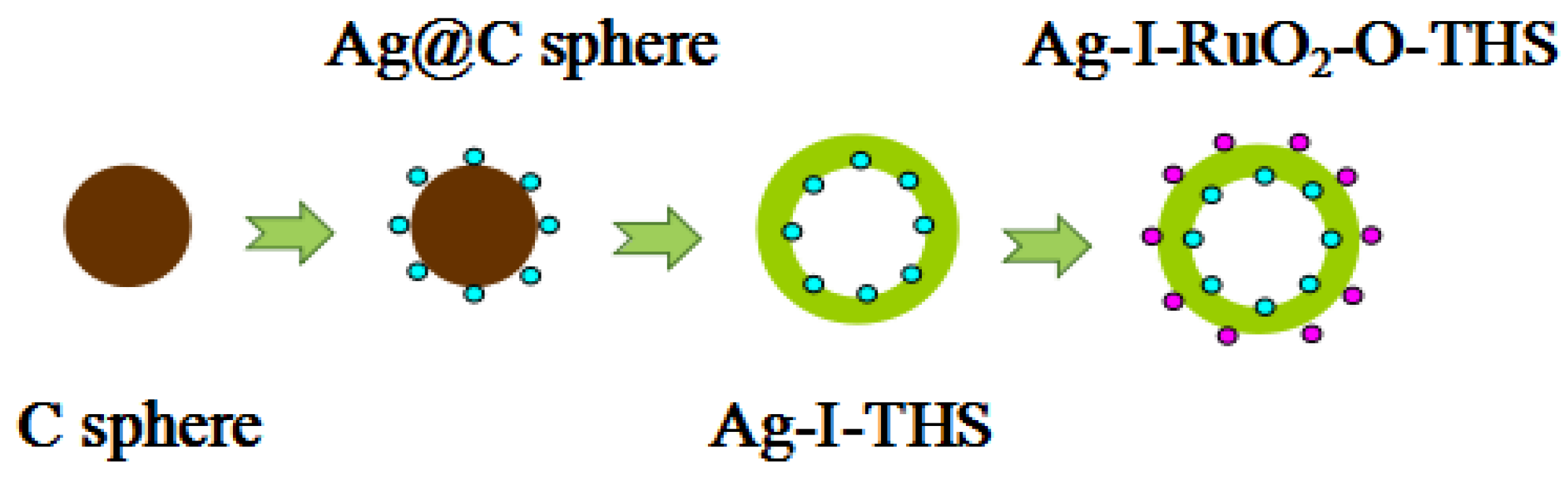
2.1.1. Synthesis of Carbon Spheres (C Sphere)
2.1.2. Synthesis of TiO2 Hollow Spheres (THS)
2.1.3. Synthesis of Ag-Loaded TiO2 Hollow Spheres on the Inner Surface (Ag-I-THS)
2.1.4. Synthesis of Ag- and RuO2-Co-Loaded TiO2 Hollow Spheres on the Inner Surface and Outer Surface (Ag-I-RuO2-O-THS)
2.1.5. Synthesis of RuO2-Loaded TiO2 Hollow Spheres on the Outer Surface (RuO2-O-THS)
2.1.6. Synthesis of RuO2- and Ag-Co-Loaded TiO2 Hollow Spheres on the Inner Surface and Outer Surface (RuO2-I-Ag-O-THS)
2.2. Characterizations
2.3. Photocatalytic Activity Evaluation
3. Results and Discussion
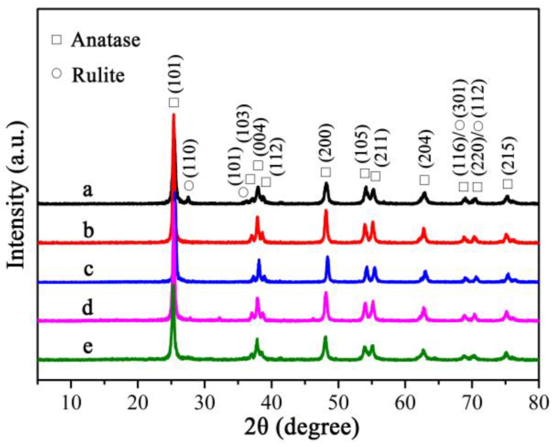
3.1. Crystal Structure
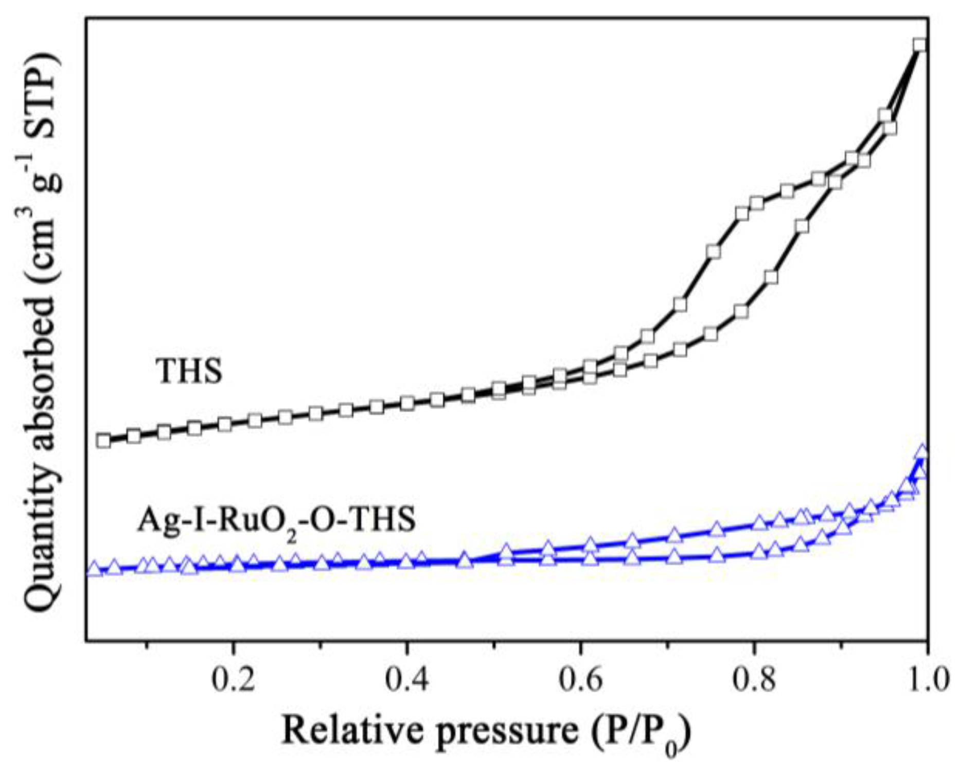
3.2. BET Analyses
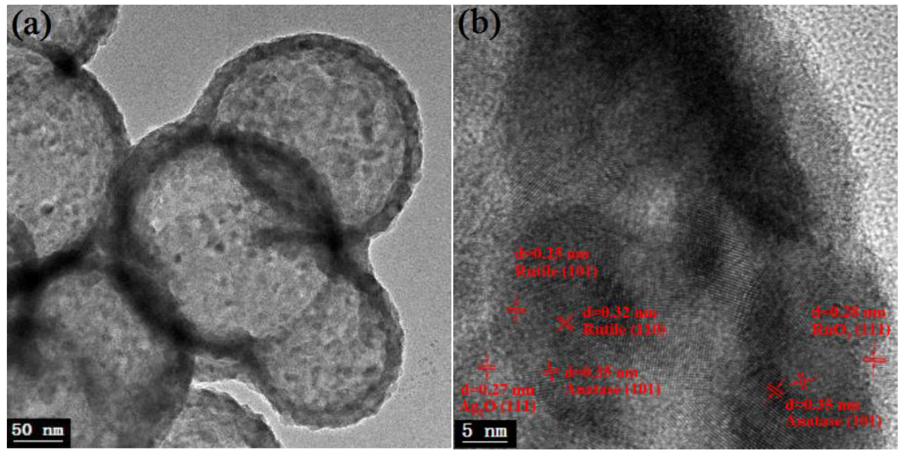
3.3. TEM Analyses
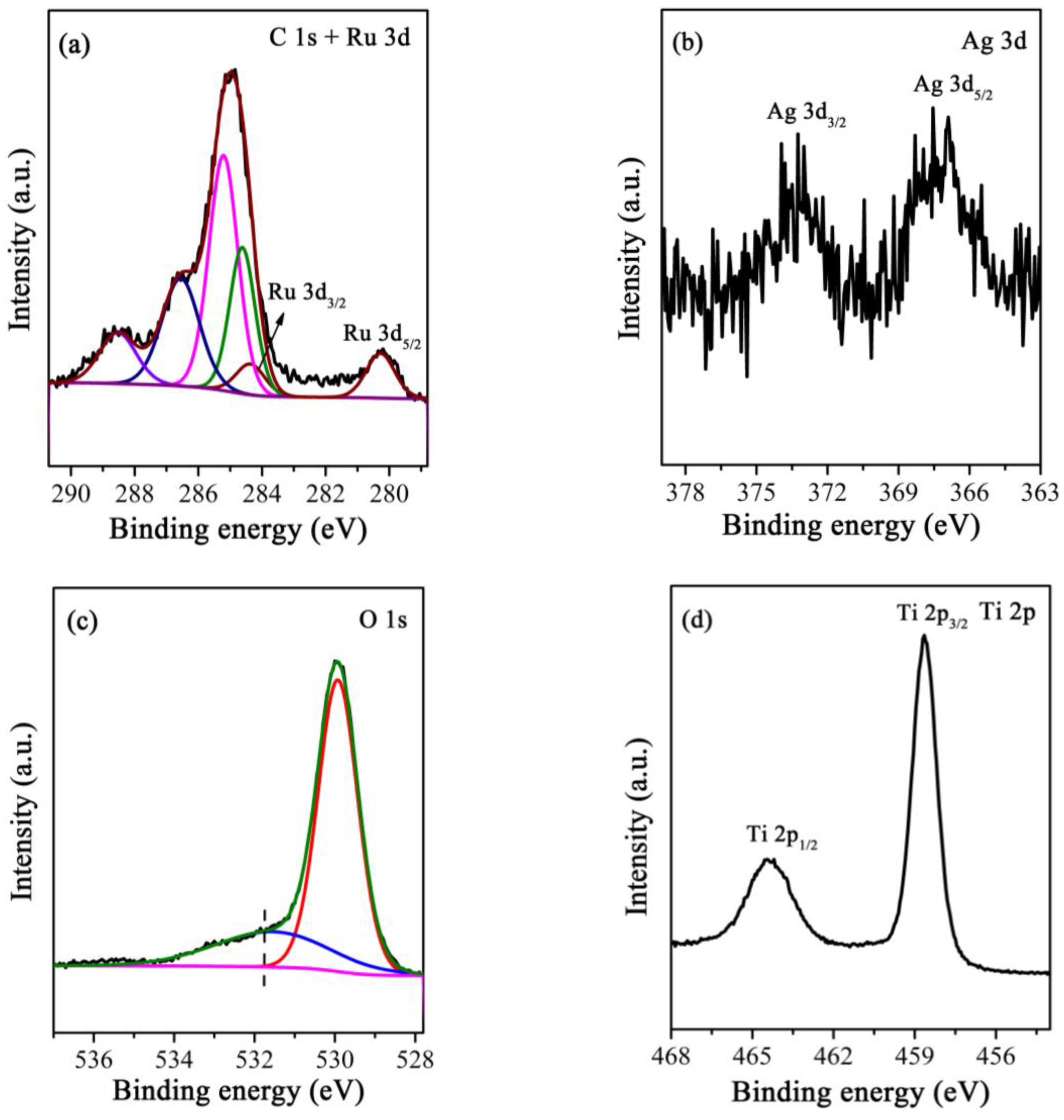
3.4. XPS Analyses
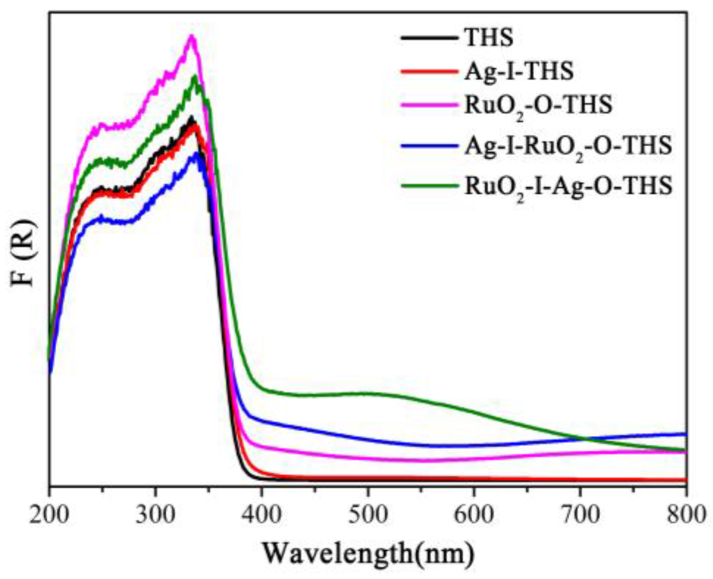
3.5. UV-Vis DRS Analyses
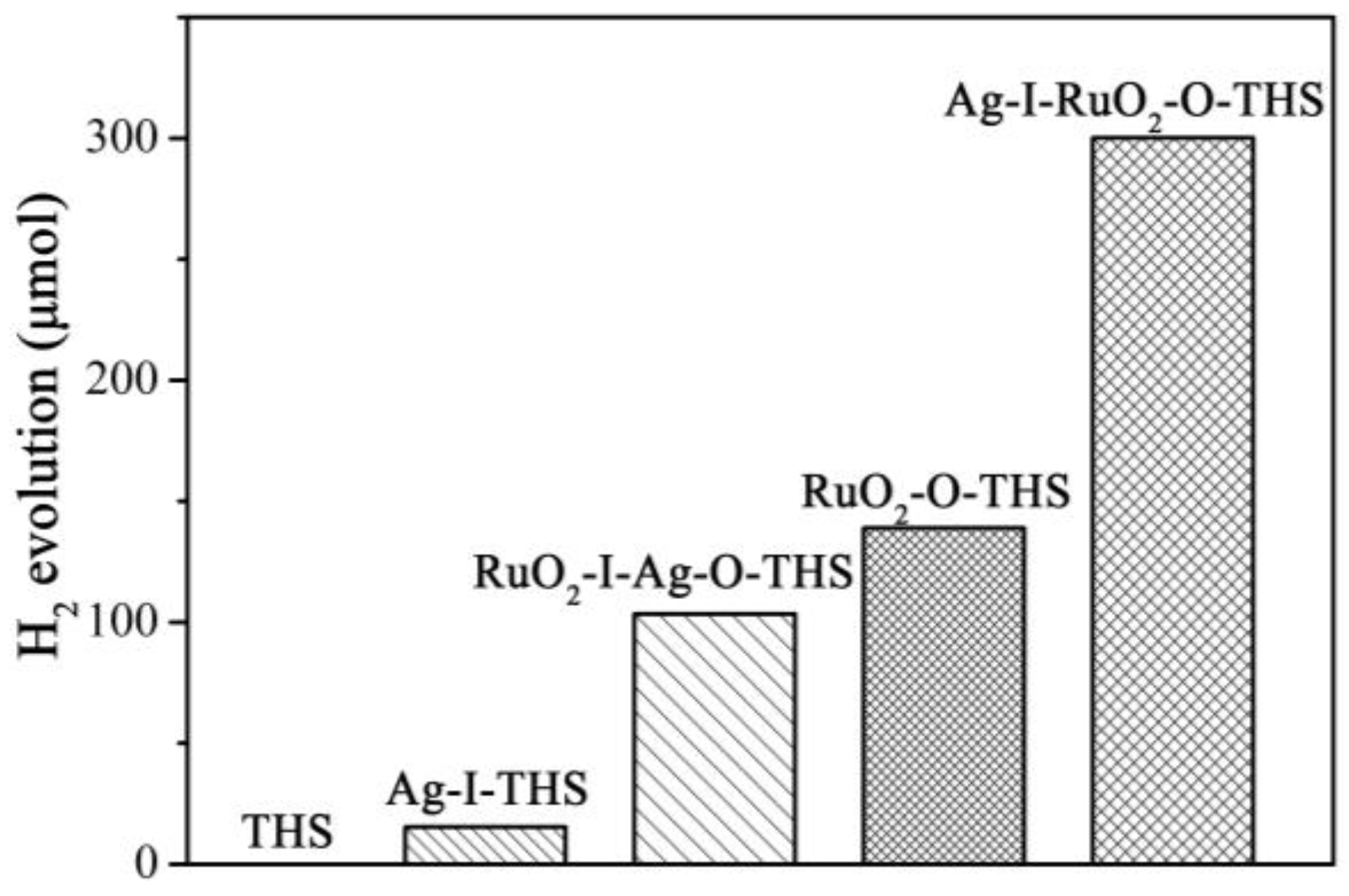
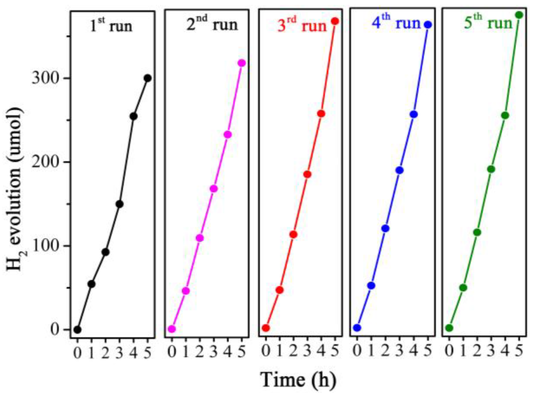
3.6. Photocatalytic Activities
4. Conclusions
Acknowledgments
Author Contributions
Conflicts of Interest
References
- Chen, X.; Shen, S.; Guo, L.; Mao, S. Semiconductor-based photocatalytic hydrogen generation. Chem. Rev. 2010, 110, 6503–6570. [Google Scholar] [CrossRef] [PubMed]
- Liu, H.; Yuan, J.; Shangguan, W.; Teraoka, Y. Visible-light-responding BiYWO6 solid solution for stoichiometric photocatalytic water splitting. J. Phys. Chem. C 2008, 112, 8521–8523. [Google Scholar] [CrossRef]
- Shimura, K.; Yoshida, T.; Yoshida, H. Photocatalytic activation of water and methane over modified gallium oxide for hydrogen production. J. Phys. Chem. C 2010, 114, 11466–11474. [Google Scholar] [CrossRef]
- Zong, X.; Wu, G.; Yan, H.; Ma, G.; Shi, J.; Wen, F.; Wang, L.; Li, C. Photocatalytic H2 evolution on MoS2/CdS catalysts under visible light irradiation. J. Phys. Chem. C 2010, 114, 1963–1968. [Google Scholar] [CrossRef]
- Fujishima, A. Electrochemical photolysis of water at a semiconductor electrode. Nature 1972, 238, 37–38. [Google Scholar] [CrossRef] [PubMed]
- Xu, H.; Reunchan, P.; Ouyang, S.; Tong, H.; Umezawa, N.; Kako, T.; Ye, J. Anatase TiO2 single crystals exposed with high-reactive {111} facets toward efficient H2 evolution. Chem. Mater. 2013, 25, 405–411. [Google Scholar] [CrossRef]
- Xiang, Q.; Yu, J.; Jaroniec, M. Synergetic effect of MoS2 and graphene as cocatalysts for enhanced photocatalytic H2 production activity of TiO2 nanoparticles. J. Am. Chem. Soc. 2012, 134, 6575–6578. [Google Scholar] [CrossRef] [PubMed]
- Hernández-Alonso, M.; Fresno, F.; Suárez, S.; Coronado, J. Development of alternative photocatalysts to TiO2: Challenges and opportunities. Energy Environ. Sci. 2009, 2, 1231–1257. [Google Scholar] [CrossRef]
- Kim, Y.; Lee, M.; Kim, H.; Lim, G.; Choi, Y.; Park, N.; Lee, W. Formation of highly efficient dye-sensitized solar cells by hierarchical pore generation with nanoporous TiO2 spheres. Adv. Mater. 2009, 21, 3668–3673. [Google Scholar] [CrossRef]
- Liu, B.; Aydil, E. Growth of oriented single-crystalline rutile TiO2 nanorods on transparent conducting substrates for dye-sensitized solar cells. J. Am. Chem. Soc. 2009, 131, 3985–3990. [Google Scholar] [CrossRef] [PubMed]
- Hoang, S.; Berglund, S.; Hahn, N.; Bard, A.; Mullins, C. Enhancing visible light photo-oxidation of water with TiO2 nanowire arrays via cotreatment with H2 and NH3: Synergistic effects between Ti3+ and N. J. Am. Chem. Soc. 2012, 134, 3659–3662. [Google Scholar] [CrossRef] [PubMed]
- Zhou, W.; Yin, Z.; Du, Y.; Huang, X.; Zeng, Z.; Fan, Z.; Zhang, H. Synthesis of few-layer MoS2 nanosheet-coated TiO2 nanobelt heterostructures for enhanced photocatalytic activities. Small 2013, 9, 140–147. [Google Scholar] [CrossRef] [PubMed]
- Shin, W.; Lee, H.; Sohn, Y.; Shin, W. Novel inkjet droplet method generating monodisperse hollow metal oxide micro-spheres. Chem. Eng. J. 2016, 292, 139–146. [Google Scholar] [CrossRef]
- Zhang, P.; Li, A.; Gong, J. Hollow spherical titanium dioxide nanoparticles for energy and environmental applications. Particuology 2015, 22, 13–23. [Google Scholar] [CrossRef]
- Yu, Y.; Cao, C.; Chen, Z.; Liu, H.; Li, P.; Dou, Z.; Song, W. Au nanoparticles embedded into the inner wall of TiO2 hollow spheres as a nanoreactor with superb thermal stability. Chem. Commun. 2013, 49, 3116–3118. [Google Scholar] [CrossRef] [PubMed]
- Du, J.; Qi, J.; Wang, D.; Tang, Z. Facile synthesis of Au@TiO2 core-shell hollow spheres for dye-sensitized solar cells with remarkably improved efficiency. Energy Environ. Sci. 2012, 5, 6914–6918. [Google Scholar] [CrossRef]
- Li, A.; Zhang, P.; Chang, X.; Cai, W.; Wang, T.; Gong, J. Gold nanorod@TiO2 yolk-shell nanostructures for visible-light-driven photocatalytic oxidation of benzyl alcohol. Small 2015, 11, 1892–1899. [Google Scholar] [CrossRef] [PubMed]
- Yang, J.; Wang, D.; Han, H.; Li, C. Roles of cocatalysts in photocatalysis and photoelectrocatalysis. Acc. Chem. Res. 2013, 46, 1900–1909. [Google Scholar] [CrossRef] [PubMed]
- Wang, D.; Hisatomi, T.; Takata, T.; Pan, C.; Katayama, M.; Kubota, J.; Domen, K. Core/shell photocatalyst with spatially separated co-catalysts for efficient reduction and oxidation of water. Angew. Chem. Int. Ed. 2013, 52, 11252–11256. [Google Scholar] [CrossRef] [PubMed]
- Bai, S.; Yin, W.; Wang, L.; Li, Z.; Xiong, Y. Surface and interface design of cocatalysts toward photocatalytic water splitting and CO2 reduction. RSC Adv. 2016, 6, 57446–57463. [Google Scholar] [CrossRef]
- Li, R.; Zhang, F.; Wang, D.; Yang, J.; Li, M.; Zhu, J.; Zhou, X.; Han, H.; Li, C. Spatial separation of photogenerated electrons and holes among {010} and {110} crystal facets of BiVO4. Nat. Commun. 2013, 4, 1432. [Google Scholar] [CrossRef] [PubMed]
- Zhang, N.; Liu, S.; Fu, X.; Xu, Y. Synthesis of M@TiO2 (M = Au, Pd, Pt) core-shell nanocomposites with tunable photoreactivity. J. Phys. Chem. C 2011, 115, 9136–9145. [Google Scholar] [CrossRef]
- Xiang, Q.; Yu, J. Graphene-based photocatalysts for hydrogen generation. J. Phys. Chem. Lett. 2013, 4, 753–759. [Google Scholar] [CrossRef] [PubMed]
- Zhang, N.; Xu, Y. Aggregation- and leaching-resistant, reusable, and multifunctional Pd@CeO2 as a robust nanocatalyst achieved by a hollow core-shell strategy. Chem. Mater. 2013, 25, 1979–1988. [Google Scholar] [CrossRef]
- Zong, X.; Yan, H.; Wu, G.; Ma, G.; Wen, F.; Wang, L.; Li, C. Enhancement of photocatalytic H2 evolution on CdS by loading MoS2 as cocatalyst under visible light irradiation. J. Am. Chem. Soc. 2008, 130, 7176–7177. [Google Scholar] [CrossRef] [PubMed]
- Inoue, Y. Photocatalytic water splitting by RuO2-loaded metal oxides and nitrides with d0- and d10-related electronic configurations. Energy Environ. Sci. 2009, 2, 364–386. [Google Scholar] [CrossRef]
- Asai, R.; Nemoto, H.; Jia, Q.; Saito, K.; Iwase, A.; Kudo, A. A visible light responsive rhodium and antimony-codoped SrTiO3 powdered photocatalyst loaded with an IrO2 cocatalyst for solar water splitting. Chem. Commun. 2014, 50, 2543–2546. [Google Scholar] [CrossRef] [PubMed]
- Higashi, M.; Domen, K.; Abe, R. Highly stable water splitting on oxynitride TaON photoanode system under visible light irradiation. J. Am. Chem. Soc. 2012, 134, 6968–6971. [Google Scholar] [CrossRef] [PubMed]
- Wang, D.; Li, R.; Zhu, J.; Shi, J.; Han, J.; Zong, X.; Li, C. Photocatalytic water oxidation on BiVO4 with the electrocatalyst as an oxidation cocatalyst: Essential relations between electrocatalyst and photocatalyst. J. Phys. Chem. C 2012, 116, 5082–5089. [Google Scholar] [CrossRef]
- Wang, S.; Qian, H.; Hu, Y.; Dai, W.; Zhong, Y.; Chen, J.; Hu, X. Facile one-pot synthesis of uniform TiO2-Ag hybrid hollow spheres with enhanced photocatalytic activity. Dalton Trans. 2013, 42, 1122–1128. [Google Scholar] [CrossRef] [PubMed]
- Grzelczak, M.; Zhang, J.; Pfrommer, J.; Hartmann, J.; Driess, M.; Antonietti, M.; Wang, X. Electro-and photochemical water oxidation on ligand-free Co3O4 nanoparticles with tunable sizes. ACS Catal. 2013, 3, 383–388. [Google Scholar] [CrossRef]
- Liu, L.; Ji, Z.; Zou, W.; Gu, X.; Deng, Y.; Gao, F.; Tang, C.; Dong, L. In situ loading transition metal oxide clusters on TiO2 nanosheets as co-catalysts for exceptional high photoactivity. ACS Catal. 2013, 3, 2052–2061. [Google Scholar] [CrossRef]
- Luo, X.; Deng, F.; Min, L.; Luo, S.; Guo, B.; Zeng, G.; Au, C. Facile one-step synthesis of inorganic-framework molecularly imprinted TiO2/WO3 nanocomposite and its molecular recognitive photocatalytic degradation of target contaminant. Environ. Sci. Technol. 2013, 47, 7404–7412. [Google Scholar] [PubMed]
- Son, J.; Chattopadhyay, J.; Pak, D. Electrocatalytic performance of Ba-doped TiO2 hollow spheres in water electrolysis. Int. J. Hydrog. Energy 2010, 35, 420–427. [Google Scholar] [CrossRef]
- Uddin, M.; Nicolas, Y.; Olivier, C.; Toupance, T.; Müller, M.; Kleebe, H.; Rachut, K.; Ziegler, J.; Klein, A.; Jaegermann, W. Preparation of RuO2/TiO2 mesoporous heterostructures and rationalization of their enhanced photocatalytic properties by band alignment investigations. J. Phys. Chem. C 2013, 117, 22098–22110. [Google Scholar] [CrossRef]
- Sarkar, D.; Ghosh, C.; Mukherjee, S.; Chattopadhyay, K. Three dimensional Ag2O/TiO2 type-II (p-n) nanoheterojunctions for superior photocatalytic activity. ACS Appl. Mater. Inter. 2013, 5, 331–337. [Google Scholar] [CrossRef] [PubMed]
- Yu, J.; Yu, H.; Cheng, B.; Zhao, X.; Yu, J.; Ho, W. The effect of calcination temperature on the surface microstructure and photocatalytic activity of TiO2 thin films prepared by liquid phase deposition. J. Phys. Chem. B 2003, 107, 13871–13879. [Google Scholar] [CrossRef]
- Ren, W.; Ai, Z.; Jia, F.; Zhang, L.; Fan, X.; Zou, Z. Low temperature preparation and visible light photocatalytic activity of mesoporous carbon-doped crystalline TiO2. Appl. Catal. B Environ. 2007, 69, 138–144. [Google Scholar] [CrossRef]
- Zhang, H.; Wang, G.; Chen, D.; Lv, X.; Li, J. Tuning photoelectrochemical performances of Ag-TiO2 nanocomposites via reduction/oxidation of Ag. Chem. Mater. 2008, 20, 6543–6549. [Google Scholar] [CrossRef]
- Zhou, W.; Liu, H.; Wang, J.; Liu, D.; Du, G.; Cui, J. Ag2O/TiO2 nanobelts heterostructure with enhanced ultraviolet and visible photocatalytic activity. ACS Appl. Mater. Interfaces 2010, 2, 2385–2392. [Google Scholar] [CrossRef] [PubMed]


© 2017 by the authors. Licensee MDPI, Basel, Switzerland. This article is an open access article distributed under the terms and conditions of the Creative Commons Attribution (CC BY) license ( http://creativecommons.org/licenses/by/4.0/).
Share and Cite
Jiang, Q.; Li, L.; Bi, J.; Liang, S.; Liu, M. Design and Synthesis of TiO2 Hollow Spheres with Spatially Separated Dual Cocatalysts for Efficient Photocatalytic Hydrogen Production. Nanomaterials 2017, 7, 24. https://doi.org/10.3390/nano7020024
Jiang Q, Li L, Bi J, Liang S, Liu M. Design and Synthesis of TiO2 Hollow Spheres with Spatially Separated Dual Cocatalysts for Efficient Photocatalytic Hydrogen Production. Nanomaterials. 2017; 7(2):24. https://doi.org/10.3390/nano7020024
Chicago/Turabian StyleJiang, Qianqian, Li Li, Jinhong Bi, Shijing Liang, and Minghua Liu. 2017. "Design and Synthesis of TiO2 Hollow Spheres with Spatially Separated Dual Cocatalysts for Efficient Photocatalytic Hydrogen Production" Nanomaterials 7, no. 2: 24. https://doi.org/10.3390/nano7020024