
Atomic Force Microscopy: A Powerful Tool to Address Scaffold Design in Tissue Engineering


Abstract
:1. Background: Advantages and Limitations
2. Working Principles and Basic Tools
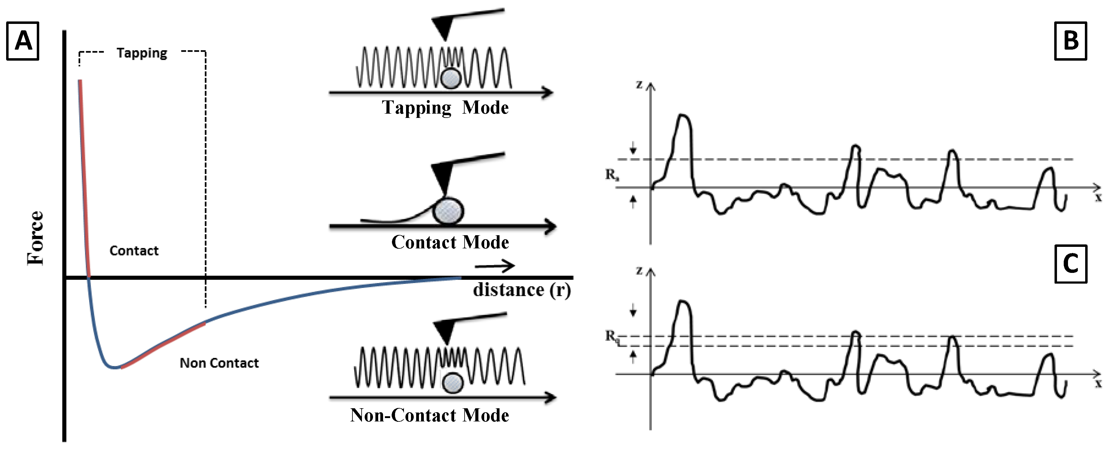
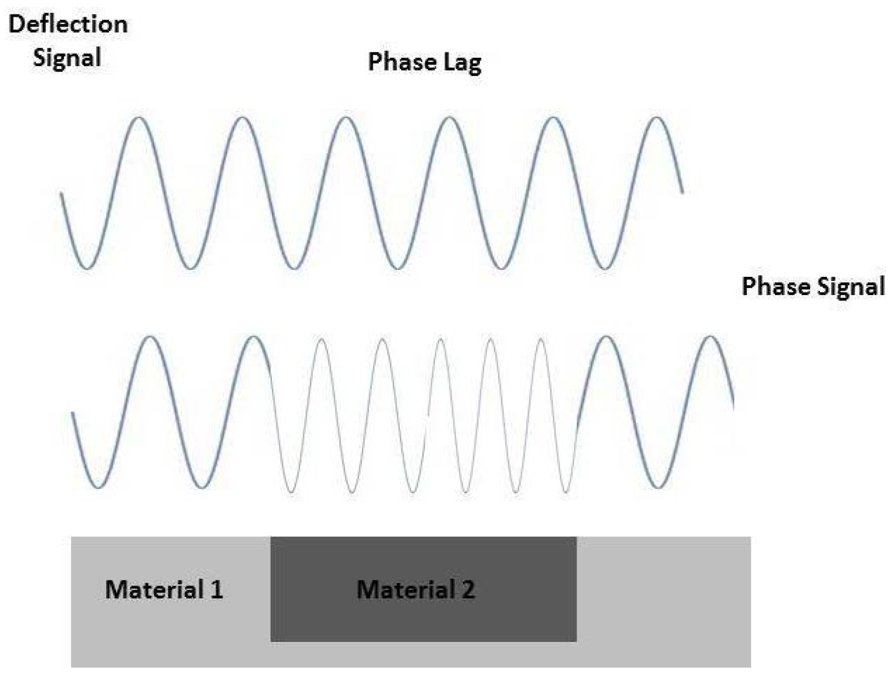
2.1. Contact, Non-Contact and Tapping Mode
2.2. Roughness Data
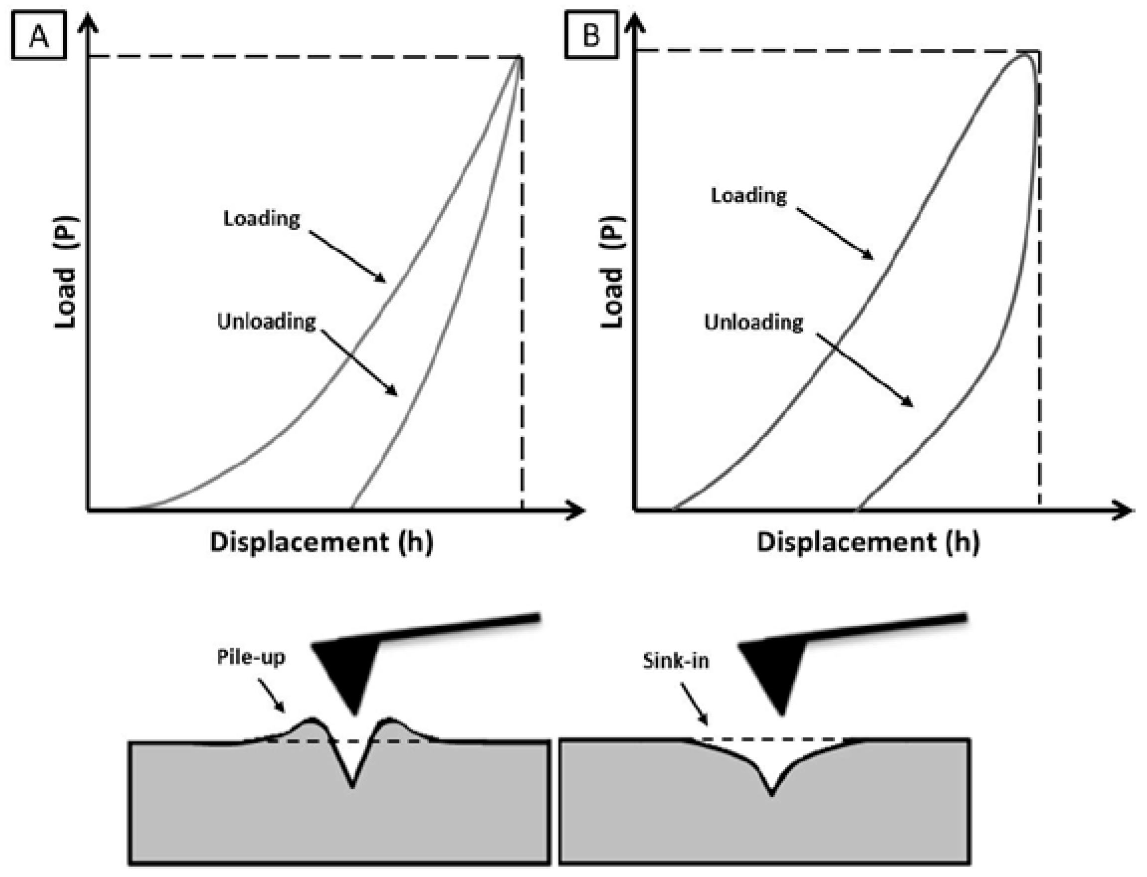
2.3. Micro\Nano Indentation
3. Major Applications in Scaffolds Design
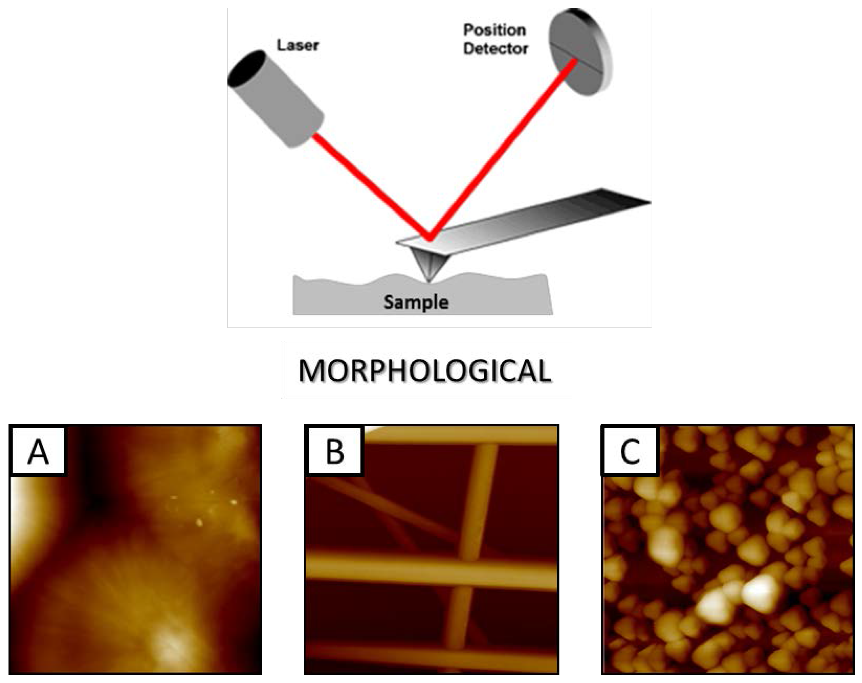
3.1. Investigation of Structural Properties
3.2. Investigation of Chemical Composition/Functionalization
4. Advanced Tools
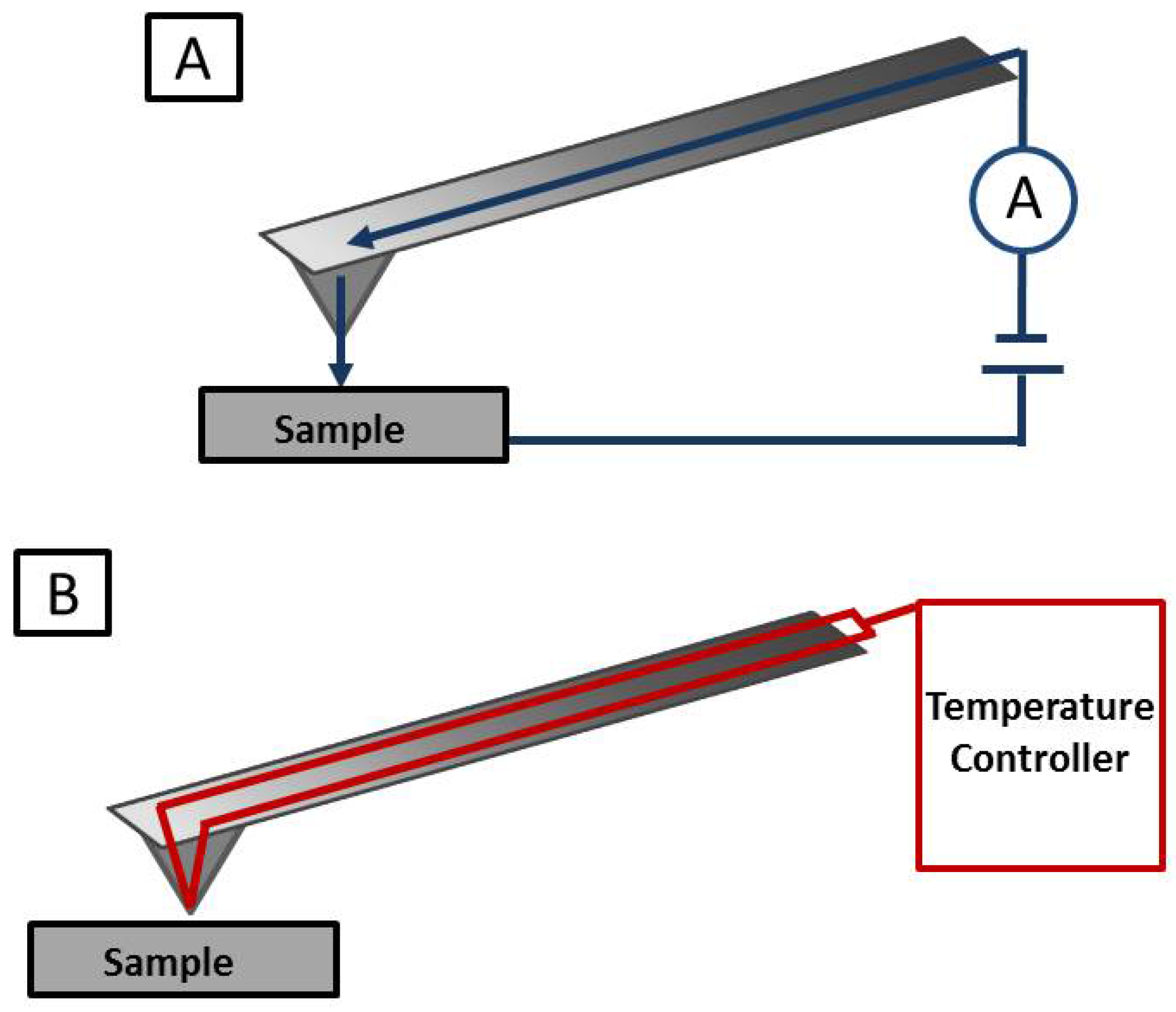
4.1. Conductive AFM
4.2. Thermal Analyses
5. Conclusions and Future Trends
Acknowledgments
Author Contributions
Conflicts of Interest
References
- Knoll, M.; Ruska, E. Contribution to geometrical electron optics (in German). Ann. Phys. 1932, 5, 607–661. [Google Scholar] [CrossRef]
- Binnig, G.; Quate, C.F.; Gerber, C. Atomic Force microscope. Phys. Rev. Lett. 1986, 56, 885. [Google Scholar] [CrossRef] [PubMed]
- Alessandrini, A.; Facci, P. AFM: A versatile tool in biophysics. Sci. Technol. 2005, 16, 65–92. [Google Scholar] [CrossRef]
- Binnig, G.; Gerber, C.; Stoll, E. Atomic resolution with atomic force microscope. Europhys. Lett. 1997, 3, 1281–1286. [Google Scholar] [CrossRef]
- Egerton, R.F. Physical Principles of Electron Microscopy: An Introduction to TEM, SEM, and AFM; Springer: New York, NY, USA, 2008. [Google Scholar]
- Binnig, G.; Rohrer, H.; Gerber, C. Surface studies by scanning tunneling microscopy. Phys. Rev. Lett. 1982, 49, 57–61. [Google Scholar] [CrossRef]
- Albrecht, T.R.; Quate, C.F. Atomic resolution imaging of a nonconductor by atomic force microscopy. J. Appl. Phys. 1987, 62, 2599–2602. [Google Scholar] [CrossRef]
- Meyer, E. Atomic Force Microscopy. Prog. Surf. Sci. 1992, 41, 3–49. [Google Scholar] [CrossRef]
- Variola, F. Atomic force microscopy in biomaterials surface science. Phys. Chem. Chem. Phys. 2015, 17, 2950–2959. [Google Scholar] [CrossRef] [PubMed]
- Burnham, N.A.; Colton, R.J. Measuring the nanomechanical properties and surface forces of materials using an atomic force microscope. J. Vac. Sci. Technol. A 1989, 7, 2906–2913. [Google Scholar] [CrossRef]
- Miyamoto, T.; Kaneko, R.; Ando, Y. Interaction force between thin film disk media and elastic solids investigated by atomic force microscope. J. Tribol. 1990, 112, 567–572. [Google Scholar] [CrossRef]
- Mizes, H.A.; Loh, K.G.; Miller, R.J.D. Submicron probe of polymer adhesion with atomic force microscopy: Dependence on topography and material inhomogeneities. Appl. Phys. Lett. 1991, 59, 2901–2903. [Google Scholar] [CrossRef]
- Creuzet, F.; Ryschenkow, G.; Arribart, H. A new tool for adhesion science: The atomic force microscope. J. Adhes. 1992, 40, 15–25. [Google Scholar] [CrossRef]
- Weisenhorn, A.L.; Maivald, P.; Butt, H.J. Measuring adhesion, attraction, and repulsion between surfaces in liquids with an atomic-force microscope. Phys. Rev. B 1992, 45, 11226–11232. [Google Scholar] [CrossRef]
- Mart, O. Modern Tribology Handbook. Measurement of Adhesion and Pull-Off Forces with the AFM; CRC: New York, NY, USA, 2001. [Google Scholar]
- Drake, B.; Prater, C.B.; Weisenhorn, A.L. Imaging crystals, polymers, and processes in water with the atomic force microscope. Science 1989, 243, 1586–1589. [Google Scholar] [CrossRef] [PubMed]
- Bustamante, C.; Rivetti, C.; Keller, D.J. Scanning force microscopy under aqueous solutions. Curr. Opin. Struct. Biol. 1997, 7, 709–716. [Google Scholar] [CrossRef]
- Yang, F.; Xu, C.Y.; Kotaki, M. Characterization of neural stem cells on electrospun poly(l-lactic acid) nanofibrous scaffold. J. Biomater. Sci. Polym. 2004, 15, 1483–1497. [Google Scholar] [CrossRef]
- Santos, N.C.; Castanho, M.A. An overview of the biophysical applications of atomic force microscopy. Biophys. Chem. 2004, 107, 133–149. [Google Scholar] [CrossRef] [PubMed]
- Borato, C.E.; Leite, F.L.; Oliveira, O.N. Layer by-layer films of poly(o-ethoxyaniline), Chitosan and Chitosan-poly(methacrylic acid) nanoparticles and their application in an electronic tongue. IEEE Trans. Dielectr. Electr. Insul. 2006, 13, 1101–1109. [Google Scholar]
- Souza, N.C.; Silva, J.R.; Pereira-da-Silva, M.A. Dynamic Scale Theory for Characterizing Surface Morphology of Layer-by-Layer Films of Poly(o-methoxyaniline). J. Nanosci. Nanotechnol. 2004, 4, 548–552. [Google Scholar] [CrossRef] [PubMed]
- Leite, F.L.; Mattoso, L.H.C.; Oliveira, O.N. The Atomic Force Spectroscopy as a Tool to Investigate Surface Forces: Basic Principles and Applications in Modern Research and Educational Topics in Microscopy E Modern Research and Educational Topics in Microscopy; Méndez-Vilas, A., Díaz, J., Eds.; Formatex: Badajoz, Spain, 2007. [Google Scholar]
- Gimzewski, G.K. Nanoscale science of single molecules using local probes. Science 1999, 283, 1683–1688. [Google Scholar] [CrossRef] [PubMed]
- Jagtap, R.N.; Ambre, A.H. Overview literature on atomic force microscopy (AFM): Basics and its important applications for polymer characterization. Indian J. Eng. Mater. Sci. 2006, 13, 368–384. [Google Scholar]
- Jalili, N.; Laxminarayana, K. A review of atomic force microscopy imaging systems: Application to molecular metrology and biological sciences. Machatronics 2004, 14, 907–945. [Google Scholar] [CrossRef]
- Braga, P.C.; Ricci, D. Methods in Molecular Biology. Atomic Force Microscopy: Biomedical Methods and Applications; Humana Press Inc.: Totowa, NJ, USA, 2004. [Google Scholar]
- Grigg, D.A.; Russell, P.E.; Griffith, J.E. Tip–sample forces in scanning probe microscopy in air and vacuum. J. Vac. Sci. Technol. A 1992, 10, 680–683. [Google Scholar] [CrossRef]
- Putman, C.A.; van der Werf, K.O.; de Grooth, B.G. A new imaging mode in atomic force microscopy based on error signal. SPIE Scanning Probe Microsc. 1992, 1693, 198–204. [Google Scholar]
- Putman, C.A.J.; Van der Werf, K.O.; De Grooth, B.G.; Van Hulst, N.F.; Greve, J. Tapping mode atomic force microscopy in liquid. Appl. Phys. Lett. 1994, 64, 2454–2456. [Google Scholar] [CrossRef]
- Haga, H.; Sasaki, S.; Kawabata, K.; Ito, E.; Ushiki, T.; Sambongi, T. Elasticity mapping of living fibroblasts by AFM and immunofluorescence observation of the cytoskeleton. Ultramicroscopy 2000, 82, 253–258. [Google Scholar] [CrossRef]
- Han, W.; Lindsay, S.M.; Jing, T. A magnetically driven oscillating probe microscope for operation in liquids. Appl. Phys. Lett. 1996, 69, 4111–4113. [Google Scholar] [CrossRef]
- Rea, I.; Giardina, P.; Longobardi, S.; Giocondo, M. Organic-inorganic Interfaces for a New Generation of Hybrid Biosensors. In Biosensors- Emerging Materials and Applications; Serra, P.A., Ed.; InTech: Rijeka, Croatia, 2011. [Google Scholar]
- Babcock, K.L.; Prater, C.B. Application Note: Phase Imaging: Beyond Topography; Bruker Veeco Instruments Inc.: Santa Barbara, CA, USA, 2010. [Google Scholar]
- Shin, E. Application Note: Surface Roughness Measurement of Media and Substrate; Park System Corp: Seoul, Korea, 2012. [Google Scholar]
- Antonio, P.D.; Lasalvia, M.; Perna, G. Scale-independent roughness value of cell membranes studied by means of AFM technique. Biochim. Biophysi. Acta 2012, 1818, 3141–3148. [Google Scholar] [CrossRef] [PubMed]
- Lampin, M.; Warocquier-Clérout, R.; Legris, C.; Degrange, M.; Sigot-Luizard, M.F. Correlation between substratum roughness and wettability, cell adhesion, and cell migration. J. Biomed. Mater. Res. 1997, 36, 99–108. [Google Scholar] [CrossRef]
- Deligianni, D.D.; Katsala, N.D.; Koutsoukos, P.G.; Missirlis, Y.F. Effect of surface roughness of hydroxyapatite on human bone marrow cell adhesion, proliferation, differentiation and detachment strength. Biomaterials 2000, 22, 87–96. [Google Scholar] [CrossRef]
- Wang, Y.; Xu, C.; Jiang, N.; Zheng, L.; Zeng, J.; Qiu, C.; Yang, H.; Xie, S. Quantitative Analysis of the Cell-Surface Roughness and Viscoelasticity for Breast Cancer Cells Discrimination Using Atomic Force Microscopy. Scanning 2016, 9999, 1–6. [Google Scholar] [CrossRef] [PubMed]
- Oraby, S.E.; Alaskari, A.M. Atomic Force Microscopy (AFM) Topographical Surface Characterization of Multilayer-Coated and Uncoated Carbide Inserts. World Acad. Sci. Eng. Technol. 2010, 46, 377–388. [Google Scholar]
- Hertz, H. On the contact of elastic solids. J Reine Angew Math. 1881, 92, 156–171, Translated and reprinted in English. In Hertz’s Miscellaneous Papers; Macmillan & Co.: London, UK, 1896. [Google Scholar]
- Sneddon, I.N. The relations between Load and Penetration in the Axisymmetric Boussi Problem for a Punch of Arbitrary Profile. Int. J. Eng. Sci. 1965, 3, 47–57. [Google Scholar] [CrossRef]
- Doerner, M.F.; Nix, W.D. A method for interpreting the data from depth-sensing indentation instruments. J. Mater. Res. 1986, 1, 601–609. [Google Scholar] [CrossRef]
- Oliver, W.C.; Pharr, G.M. An improved technique for determining hardness and elastic modulus using load and displacement sensing indentation experiments. J. Mater. Res. 1992, 7, 1564–1583. [Google Scholar] [CrossRef]
- Oliver, W.C.; Pharr, G.M. Measurement of hardness and elastic modulus by instrumented indentation: Advances in understanding and refinements to methodology. J. Mater. Res. 2004, 19, 3–20. [Google Scholar] [CrossRef]
- Marrese, M.; Guarino, V.; Ambrosio, L. Microscopic Approach for Testing Mechanical Properties of Hard Tissues. In Reference Module in Materials Science and Materials Engineering (MATS); Elsevier: Amsterdam, The Netherlands, 2016. [Google Scholar]
- Ma, Z.S.; Zhou, Y.C.; Long, S.G.; Lu, C.S. A new method to determine the elastoplastic properties of ductile materials by conical indentation. J. Sci. China. Phys. Mech. Astron. 2012, 55, 1032–1036. [Google Scholar] [CrossRef]
- Johnson, K.L.; Kendall, K.; Roberts, A.D. Surface energy and the contact of elastic solids. Proc. R. Soc. Lond. A 1971, 324, 301–313. [Google Scholar] [CrossRef]
- Derjaguin, B.V.; Müller, V.M.; Toporov, Y.P. Effect of contact deformations on the adhesion of particles. J. Colloid Interface Sci. 1975, 9, 314–326. [Google Scholar] [CrossRef]
- Tabor, D. Surface forces and surface interactions. J. Colloid Interface Sci. 1977, 58, 2–13. [Google Scholar] [CrossRef]
- Kucharski, S.; Jarząbek, D. Depth Dependence of Nanoindentation Pile-Up Patterns in Copper Single Crystals. Metall. Mater. Trans. A 2014, 45, 4997. [Google Scholar] [CrossRef]
- Jee, A.Y.; Lee, M. Comparative analysis on the nanoindentation of polymers using atomic force microscopy. Polym. Test. 2010, 29, 95–99. [Google Scholar] [CrossRef]
- O’Brien, F.J. Biomaterials & scaffolds for tissue engineering. Mater. Today 2011, 14, 88–95. [Google Scholar]
- Guarino, V.; Veronesi, F.; Marrese, M.; Giavaresi, G.; Ronca, A.; Sandri, M.; Tampieri, A.; Fini, M.; Ambrosio, L. Needle-like ion-doped hydroxyapatite crystals influence osteogenic properties of PCL composite scaffolds. Biomed. Mater. 2016, 11, 015018. [Google Scholar] [CrossRef] [PubMed]
- Cirillo, V.; Guarino, V.; Alvarez-Perez, M.A.; Marrese, M.; Ambrosio, L. Optimization of fully aligned bioactive electrospun fibers for “in vitro” nerve guidance. J. Mater. Sci.: Mater. Med. 2013. [Google Scholar] [CrossRef] [PubMed]
- Guarino, V.; Gloria, A.; Raucci, M.G.; De Santis, R.; Ambrosio, L. Bio-inspired cell instructive composite platforms for bone regeneration. Int. Mater. Rev. 2012, 57, 256–275. [Google Scholar] [CrossRef]
- Guaccio, A.; Guarino, V.; Alvarez Perez, M.A.; Cirillo, V.; Netti, P.A.; Ambrosio, L. Influence of electrospun fiber mesh size on hMSC oxygen metabolism in 3D collagen matrices: Experimental and theoretical evidences. Biotech. Bioeng. 2011, 108, 1965–1976. [Google Scholar] [CrossRef] [PubMed]
- Wan Abdul Khodir, W.; Guarino, V.; Alvarez-Perez, M.A.; Cafiero, C.; Ambrosio, L. Trapping tetracycline-loaded nanoparticles into polycaprolactone fiber networks for periodontal regeneration therapy. J. Bioact. Comp. Pol. 2013, 28, 258–273. [Google Scholar] [CrossRef]
- Li, C.; Vepari, C.; Jin, H.J.; Kim, H.J. Electrospun silk-BMP-2 scaffolds for bone tissue engineering. Biomaterials 2006, 27, 3115–3124. [Google Scholar] [CrossRef] [PubMed]
- Zhang, Y.Z.; Feng, Y.; Huang, Z.M. Fabrication of porous electrospun nanofibres. Nanotechnology 2006, 17, 901–908. [Google Scholar] [CrossRef]
- Magonov, S.N.; Elings, V.; Whangbo, M.H. Phase imaging and stiffness in tapping-mode atomic force microscopy. Surf. Sci. 1997, 375, 385–391. [Google Scholar] [CrossRef]
- Cronin-Golomb, M.; Sahin, O. High-resolution nanomechanical analysis of suspended electrospun silk fibers with the torsional harmonic atomic force microscope. Beilstein J. Nanotechnol. 2013, 4, 243–248. [Google Scholar] [CrossRef] [PubMed]
- Pappa, A.M.; Karagkiozaki, V.; Krol, S. Oxygen-plasma-modified biomimetic nanofibrous scaffolds for enhanced compatibility of cardiovascular implants. Beilstein J. Nanotechnol. 2015, 6, 254–262. [Google Scholar] [CrossRef] [PubMed]
- Chlanda, A.; Rebis, J.; Kijénska, E. Quantitative imaging of electrospun fibers by PeakForce QuantitativeNanoMechanics atomic force microscopy using etched scanning probes. Micron 2015, 72, 1–7. [Google Scholar] [CrossRef] [PubMed]
- Passeri, D.; Rossi, M.; Tamburri, E. Mechanical characterization of polymeric thin films by atomic force microscopy based techniques. Anal. Bioanal. Chem. 2013, 405, 1463–1478. [Google Scholar] [CrossRef] [PubMed]
- Scott, W.W.; Bhushan, B. Use of phase imaging in atomic force microscopy for measurement of viscoelastic contrast in polymer nanocomposites and molecularly thick lubricant films. Ultramicroscopy 2003, 97, 151–169. [Google Scholar] [CrossRef]
- Cárdenas, G.; Anaya, P.; del Rio, R. Scanning Electron Microscopy And Atomic Force Microscopy Of Chitosan. Composite Films. J. Chil Chem. Soc. 2010, 55, 352–358. [Google Scholar] [CrossRef]
- Stan, C.S.; Popa, M.; Olariu, M. Synthesis and Characterization of PSSA-Polyaniline Composite with an Enhanced Processability in Thin Films. Open Chem. 2015, 13, 467–476. [Google Scholar] [CrossRef]
- Gambardella, A.; Bianchi, M.; Kaciulis, S.; Mezzi, A.; Brucale, M.; Cavallini, M.; Herrmannsdoerfer, T.; Chanda, G.; Uhlarz, M.; Cellini, A.; et al. Magnetic hydroxyapatite coatings as a new tool in medicine: A scanning probe investigation. Mater. Sci. Eng. C 2016, 62, 444–449. [Google Scholar] [CrossRef] [PubMed]
- Iannotti, V.; Ausanio, G.; Campana, C.; D’Orazio, F.; Hison, C.; Lucari, F.; Lanotte, L. Magnetic anisotropy in Ni-Si nanoparticle films produced by ultrashort pulsed laser deposition. J. Magn. Magn. Mater. 2008, 320, e594–e598. [Google Scholar] [CrossRef]
- Lee, I.; Chan, K.Y.; Phillips, D.L. Atomic force microscopy of platinum nanoparticles prepared on highly oriented pyrolytic graphite. Ultramicroscopy 1998, 75, 69–76. [Google Scholar] [CrossRef]
- Lacava, L.M.; Lacava, B.M.; Azevedo, R.B. Nanoparticle sizing: A comparative study using atomic force microscopy, transmission electron microscopy, and ferromagnetic resonance. J. Magn. Magn. Mater. 2001, 225, 79–83. [Google Scholar] [CrossRef]
- Klapetek, P.; Valtr, M.; Nečas, D. Atomic force microscopy analysis of nanoparticles in non-ideal conditions. Nanosc. Res. Lett. 2011, 6, 514–523. [Google Scholar] [CrossRef] [PubMed]
- Baer, D.R.; Gaspar, D.J.; Nachimuthu, P.; Techane, S.D.; Castner, D.G. Application of surface chemical analysis tools for characterization of nanoparticles. Anal. Bioanal. Chem. 2010, 396, 983–1002. [Google Scholar] [CrossRef] [PubMed]
- Vakarelski, I.U.; Brown, S.C.; Moudgil, B.M.; Higashitani, K. Nanoparticle–terminated scanning probe microscopy tips and surface samples. Adv. Powder Technol. 2007, 18, 605–614. [Google Scholar] [CrossRef]
- Cross, S.E.; Jin, Y.S.; Rao, J. Nanomechanical analysis of cells from cancer patients. Nat. Nanotechnol. 2007, 2, 780–783. [Google Scholar] [CrossRef] [PubMed]
- Eaton, P.; Zuzarte-Luis, V.; Mota, M.M. Infection by Plasmodium changes shape and stiffness of hepatic cells. Nanomedicine 2012, 8, 17–19. [Google Scholar] [CrossRef] [PubMed]
- Girasole, M.; Pompeo, G.; Cricenti, A. Roughness of the plasma membrane as an independent morphological parameter to study RBCs: A quantitative atomic force microscopy investigation. Biochim. Biophys Acta 2007, 1768, 1268–1276. [Google Scholar] [CrossRef] [PubMed]
- Aigner, T.; Schmitz, N.; Haag, J. Nanomedicine: AFM tackles osteoarthritis. Nat. Nanotechnol. 2009, 4, 144–145. [Google Scholar] [CrossRef] [PubMed]
- Jiang, T.; Kumbar, S.G.; Nair, L.S. Biologicallyactive chitosan systems for tissue engineering and regenerative medicine. Curr. Top. Med. Chem. 2008, 8, 354–364. [Google Scholar] [PubMed]
- Han, W.; Serry, F.M. Force Spectroscopy with the Atomic Force Microscope; Application Note; Agilent Technologies: Palo Alto, CA, USA, 2008; Available online: http://cp.literature.agilent.com/litweb/pdf/5989–8215EN.pdf (accessed on 24 November 2015).
- Clausen-Schaumann, H.; Seitz, M.; Krautbauer, R.; Gaub, H.E. Force spectroscopy with single bio-molecules. Curr. Opin. Chem. Biol. 2000, 4, 524–530. [Google Scholar] [CrossRef]
- Rief, M.; Gautel, M.; Oesterhelt, F.; Fernandez, J.M.; Gaub, H.E. Reversible unfolding of individual titin immunoglobulin domains by AFM. Science 1997, 276, 1109–1112. [Google Scholar] [CrossRef] [PubMed]
- Besta, R.B.; Brockwell, D.J.; Toca-Herrera, J.S.; Blake, A.W.; Alastair Smith, D.; Radford, S.E.; Clark, J. Force mode atomic force microscopy as a tool for protein folding studies. Anal. Chim. Acta 2003, 479, 87–105. [Google Scholar] [CrossRef]
- Fowler, S.B.; Best, R.B.; Herrera, J.L.T.; Rutherford, T.J.; Steward, A.; Paci, E.; Karplus, M.; Clarke, J. Mechanical Unfolding of a Titin Ig Domain: Structure of Unfolding Intermediate Revealed by Combining AFM, Molecular Dynamics Simulations, NMR and Protein Engineering. J. Mol. Biol. 2002, 322, 841–849. [Google Scholar] [CrossRef]
- Hughes, M.L.; Dougan, L. The physics of pulling polyproteins: A review of single molecule force spectroscopy using the AFM to study protein unfolding. Rep. Prog. Phys. 2016, 79, 076601. [Google Scholar] [CrossRef] [PubMed]
- Hinterdorfer, P.; Dufrêne, Y.F. Detection and localization of single molecular recognition events using atomic force microscopy. Nat. Methods 2006, 3, 347–355. [Google Scholar] [CrossRef] [PubMed]
- Lee, G.U.; Chrisey, L.A.; Colton, R.J. Direct measurement of the forces between complementary strands of DNA. Science 1994, 266, 771–773. [Google Scholar] [CrossRef] [PubMed]
- Rief, M.; Clausen-Schaumann, H.; Gaub, H.E. Sequence-dependent mechanics of single DNA molecules. Nat. Struct. Biol. 1999, 6, 346–349. [Google Scholar] [PubMed]
- Yu, X.; Burnham, N.A.; Mallick, R.B. A systematic AFM-based method to measure adhesion differences between micron-sized domains in asphalt binders. Fuel 2013, 113, 443–447. [Google Scholar] [CrossRef]
- Helenius, J.; Heisenberg, C.P.; Gaub, H.E. Single-cell force spectroscopy. J. Cell Sci. 2008, 121, 1785–1791. [Google Scholar] [CrossRef] [PubMed]
- Bertoncini, P.; Le Chevalier, S.; Lavenus, S.; Layrolle, P.; Louarn, G. Early adhesion of human mesenchymal stem cells on TiO2 surfaces studied by single-cell force spectroscopy measurements. J. Mol. Recogn. 2012, 25, 262–269. [Google Scholar] [CrossRef] [PubMed]
- Taubenberger, A.V.; Hutmacher, D.W.; Muller, D.J. Single-Cell Force Spectroscopy, an Emerging Tool to Quantify Cell Adhesion to Biomaterials. Tissue Eng. Part B 2014, 20, 40–55. [Google Scholar] [CrossRef] [PubMed]
- Avila, A.; Bhushan, B. Electrical Measurement Techniques in Atomic Force Microscopy. Crit. Rev. Solid State Mater. Sci. 2010, 35, 38–51. [Google Scholar] [CrossRef]
- Conductive Atomic Force Microscopy. Available online: http://www.nrel.gov/pv/measurements/conductive_atomic.html (accessed on 24 November 2015).
- Barisci, J.N.; Stella, R.; Spinks, G.M.; Wallace, G.G. Characterisation of the topography and surface potential of electrodeposited conducting polymer films using atomic force and electric force microscopies. Electrochim. Acta 2000, 46, 519–531. [Google Scholar] [CrossRef]
- Han, D.H.; Lee, H.J.; Park, S.M. Electrochemistry of conductive polymers XXXV: Electrical and morphological characteristics of polypyrrole films prepared in aqueous media studied by current sensing atomic force microscopy. Electrochim. Acta 2005, 50, 3085–3092. [Google Scholar] [CrossRef]
- Pelto, J.M.; Haimi, S.P.; Siljander, A.S.; Miettinen, S.S.; Tappura, K.M.; Higgins, M.J.; Wallace, G.G. Surface properties and interaction forces of biopolymer-doped conductive polypyrrole surfaces by atomic force microscopy. Langmuir 2013, 29, 6099–6108. [Google Scholar] [CrossRef] [PubMed]
- Lee, H.; Cooper, R.; Wang, K. Nano-Scale Characterization of a Piezoelectric Polymer (Polyvinylidene Difluoride, PVDF). Sensors 2008, 8, 7359–7368. [Google Scholar] [CrossRef] [PubMed]
- Harding, L.; King, W.P.; Dai, X. Nanoscale Characterisation and Imaging of Partially Amorphous Materials using Local Thermomechanical Analysis and Heated Tip AFM. Pharm. Res. 2007, 24, 2048–2054. [Google Scholar] [CrossRef] [PubMed]
- Mueller, T. Quantitative Nanoscale Characterisation. Materials Today; Veeco Instruments Inc.; Elsevier: Santa Barbara, CA, USA, 2009. [Google Scholar]
- Bozec, L.; Odlyha, M. Thermal Denaturation Studies of Collagen by Microthermal Analysis and Atomic Force Microscopy. Biophys. J. 2011, 101, 228–236. [Google Scholar] [CrossRef] [PubMed]
- Frewin, C.L. Immunology and Microbiology. Atomic Force Microscopy Investigations into Biology–From Cell to Protein; InTech: Rijeka, Croatia, 2012. [Google Scholar]
- West, J.L.; Halas, N.J. Applications of nanotechnology to biotechnology commentary. Curr. Opin. Biotechnol. 2000, 11, 215–217. [Google Scholar] [CrossRef]
- Ando, T. High-speed atomic force microscopy coming of age. Nanotechnology 2012, 23, 062001–062029. [Google Scholar] [CrossRef] [PubMed]
- Uchihashi, T.; Kodera, N.; Ando, T. Guide to video recording of structure dynamics and dynamic processes of proteins by high-speed atomic force microscopy. Nat. Protoc. 2012, 7, 1193–1206. [Google Scholar] [CrossRef] [PubMed]
- Holthausen, J.T.; van Loenhout, M.T.; Sanchez, H. Effect of the BRCA2 CTRD domain on RAD51 filaments analyzed by an ensemble of single molecule techniques. Nucleic Acids Res. 2011, 39, 6558–6567. [Google Scholar] [CrossRef] [PubMed]
- Kufer, S.K.; Puchner, E.M.; Gumpp, H. Single-molecule cutand-paste surface assembly. Science 2008, 319, 594–596. [Google Scholar] [CrossRef] [PubMed]
- Mechler, A.; Piorek, B.; Lal, R. Nanoscale velocity–drag force relationship in thin liquid layers measured by atomic force microscopy. Appl. Phys. Lett. 2004, 85, 3881–3883. [Google Scholar] [CrossRef]
- Quist, A.; Chand, A.; Ramachandran, S. Piezoresistive cantilever based nanoflow and viscosity sensor for microchannels. Lab Chip. 2006, 6, 1450–1454. [Google Scholar] [CrossRef] [PubMed]
- Xie, H.; Haliyo, D.S.; Regnier, S. A versatile atomic force microscope for three dimensional nanomanipulation and nanoassembly. Nanotechnology 2009, 20. [Google Scholar] [CrossRef] [PubMed]
- Carvalho, F.A.; Santos, N.C. Atomic Force Microscopy-based Force Spectroscopy—Biological and Biomedical Applications. IUBMB Life 2012, 64, 465–472. [Google Scholar] [CrossRef] [PubMed]
- Tang, Q.; Shi, S.Q.; Zhou, L. Nanofabrication with atomic force microscopy. J. Nanosci. Nanotechnol. 2004, 4, 948–963. [Google Scholar] [CrossRef] [PubMed]


| AFM Modes of Operation | Working Principle | Advantage | Disadvantage |
|---|---|---|---|
| Contact Mode |
|
|
|
| Non-contact Mode |
|
|
|
| Tapping Mode |
|
|
|
© 2017 by the authors. Licensee MDPI, Basel, Switzerland. This article is an open access article distributed under the terms and conditions of the Creative Commons Attribution (CC BY) license ( http://creativecommons.org/licenses/by/4.0/).
Share and Cite
Marrese, M.; Guarino, V.; Ambrosio, L. Atomic Force Microscopy: A Powerful Tool to Address Scaffold Design in Tissue Engineering. J. Funct. Biomater. 2017, 8, 7. https://doi.org/10.3390/jfb8010007
Marrese M, Guarino V, Ambrosio L. Atomic Force Microscopy: A Powerful Tool to Address Scaffold Design in Tissue Engineering. Journal of Functional Biomaterials. 2017; 8(1):7. https://doi.org/10.3390/jfb8010007
Chicago/Turabian StyleMarrese, Marica, Vincenzo Guarino, and Luigi Ambrosio. 2017. "Atomic Force Microscopy: A Powerful Tool to Address Scaffold Design in Tissue Engineering" Journal of Functional Biomaterials 8, no. 1: 7. https://doi.org/10.3390/jfb8010007