
Medical Textiles as Vascular Implants and Their Success to Mimic Natural Arteries

Abstract
:1. Introduction

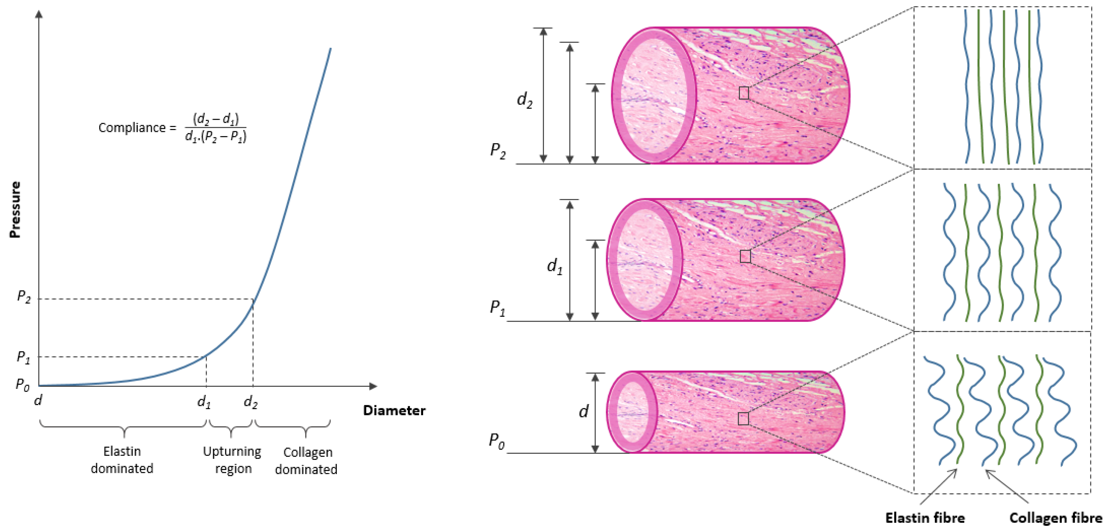
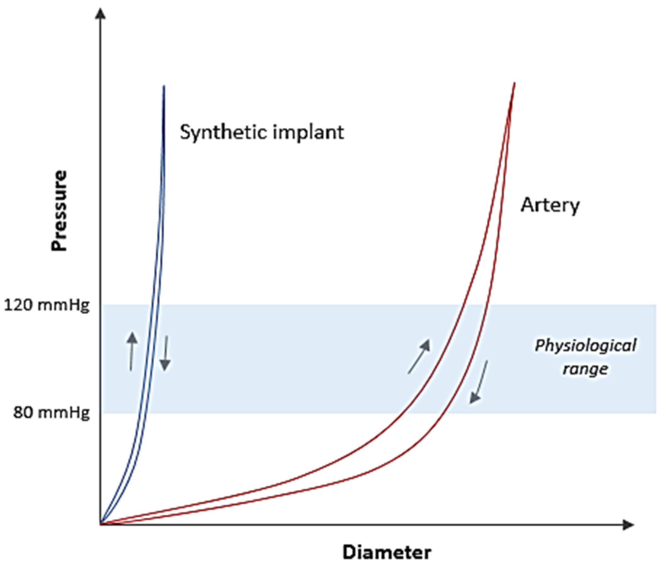
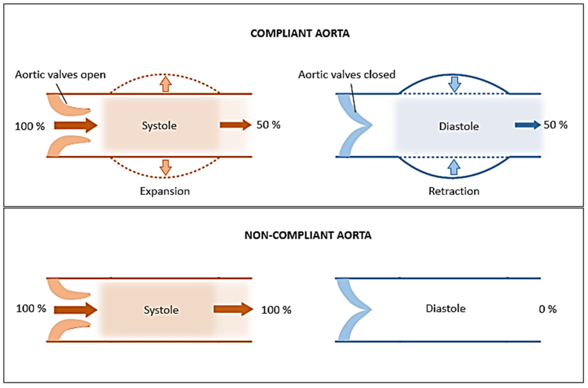
2. Artery: Structure and Mechanical Behaviour

3. Textile Structures as Vascular Implants
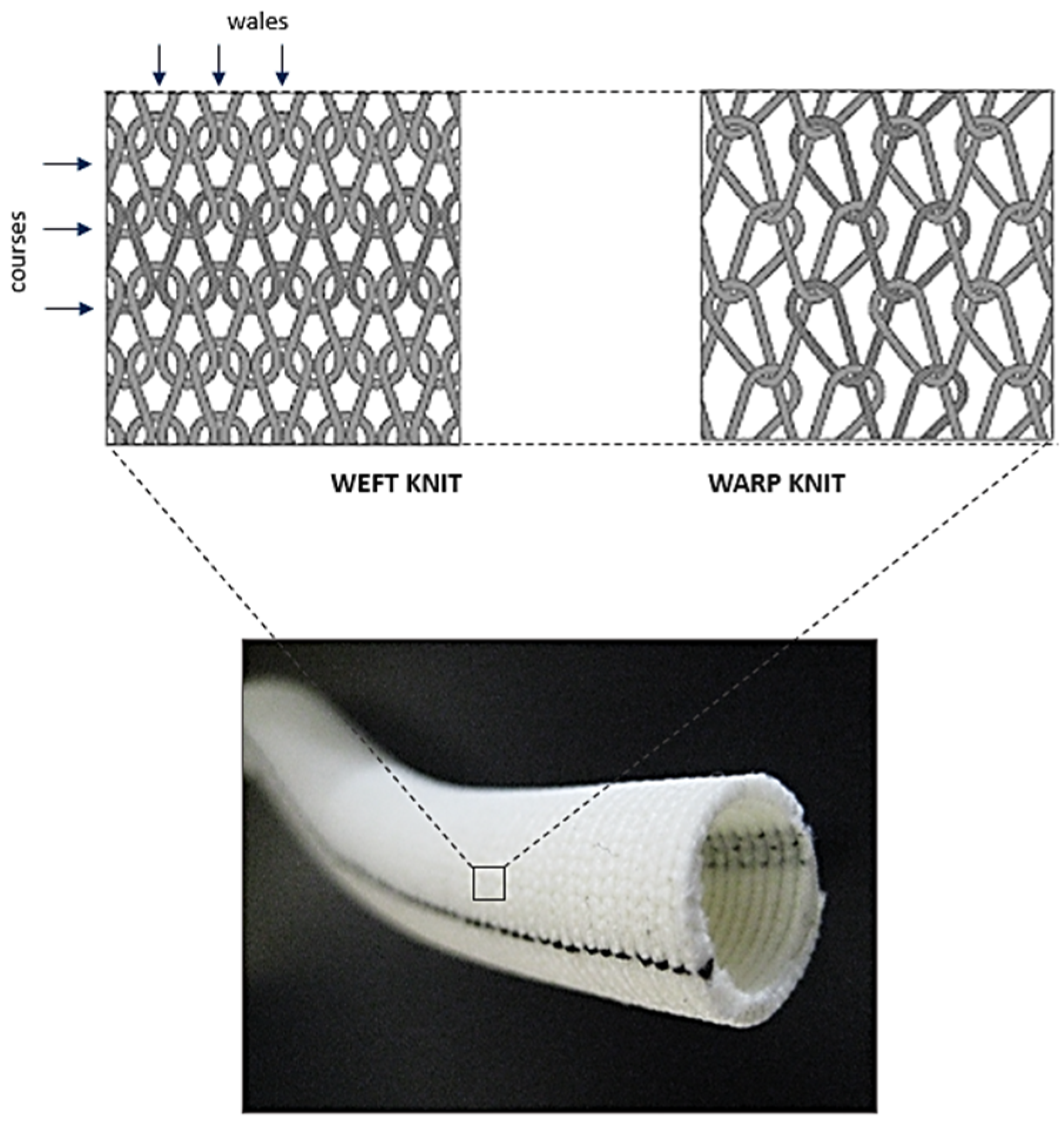
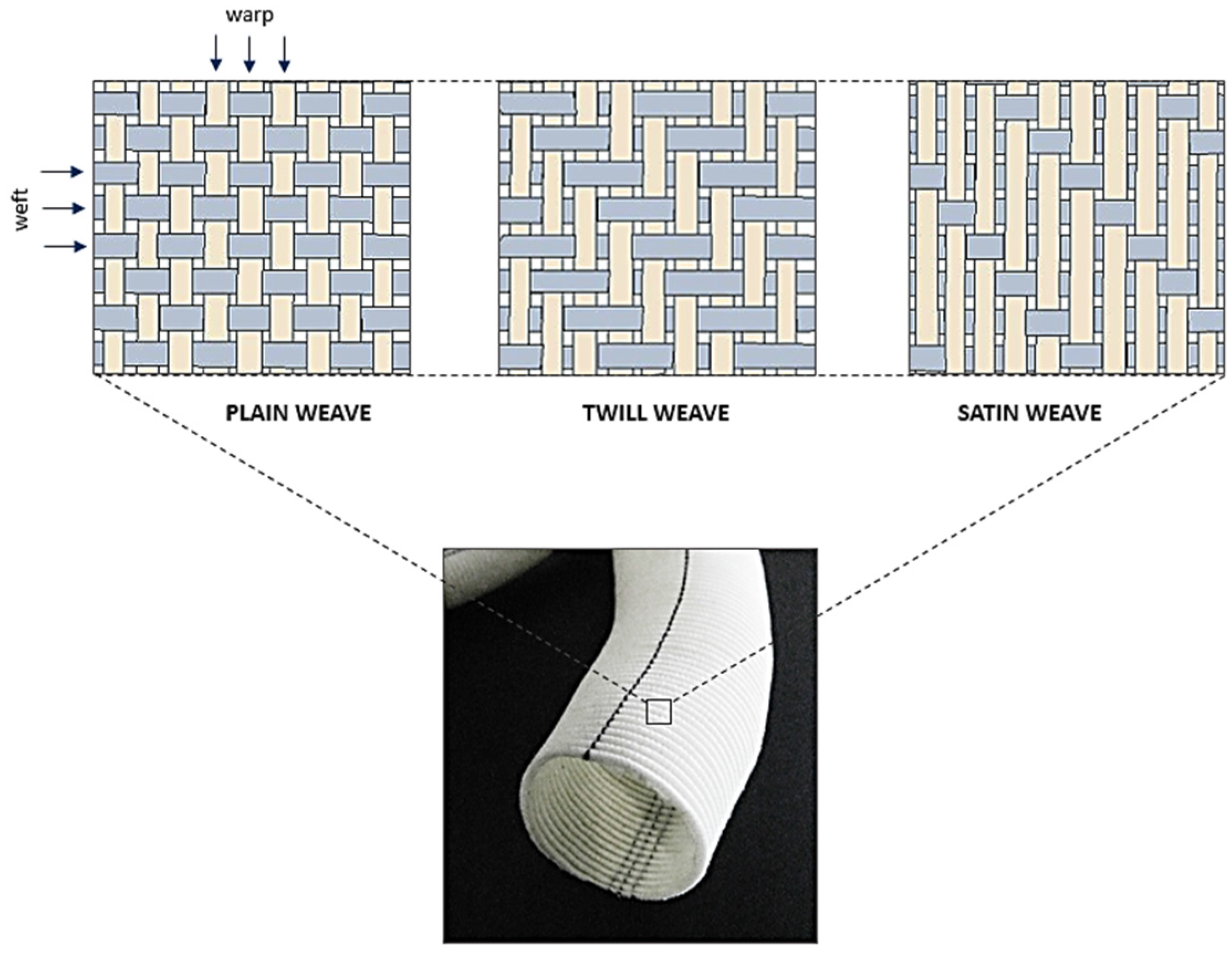
3.1. Weaving


| Structure | Component | Elastic Modulus (MPa) |
|---|---|---|
| Artery | Elastin | 0.6–1 |
| Collagen | 1000 | |
| Smooth Muscle | 0.1 | |
| Woven graft | Dacron® Polyester | 800–900 |
| Stainless steel* | 190 × 103–210 × 103 |
| Structure | Compliance (mmHg × 10−2) |
|---|---|
| Artery | 7.4 |
| Vein | 2.7 |
| Dacron® Polyester (Woven) | 1.9 |
| Dacron® Polyester (Knitted) | 2.3 |

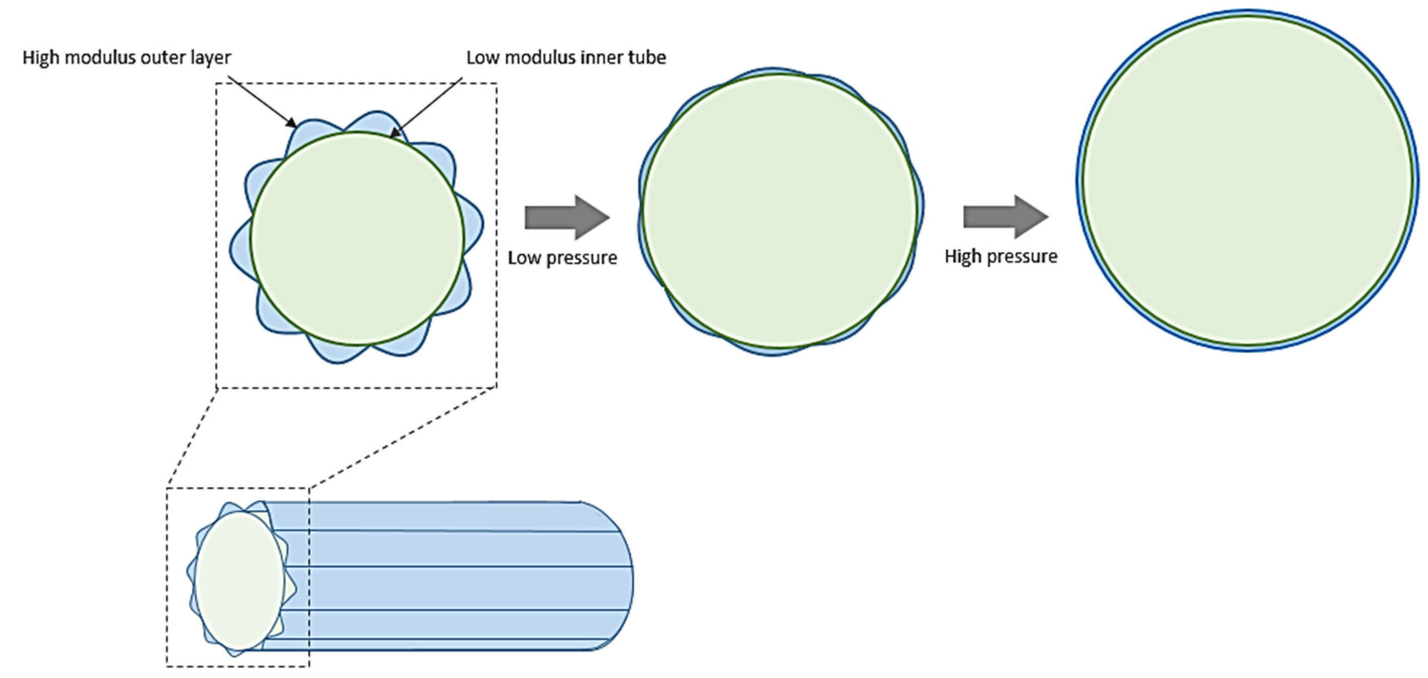
3.2. Knitting
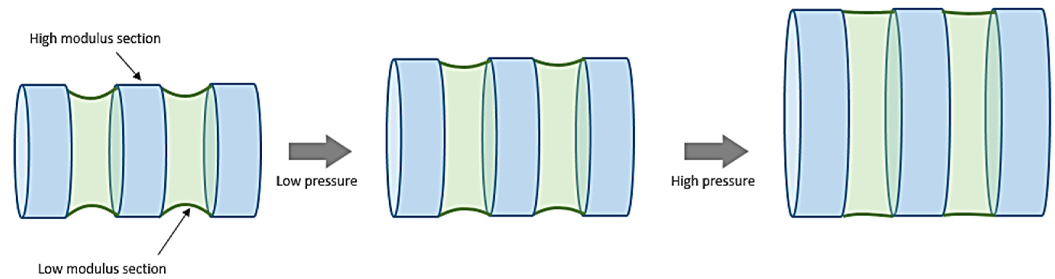
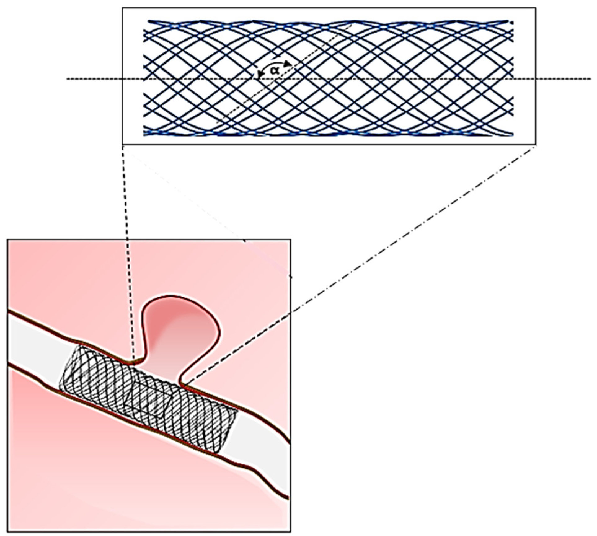
3.3. Braiding
| Trade Name | Manufacturer | Application | Material | Design Feature |
|---|---|---|---|---|
| PIPELINE® | ev3 Inc. | Flow diverter stent | Cobalt-Chromium + Platinum | Single layer braided tube |
| p64® | Phenox GmbH | Nitinol | ||
| LEO® PLUS | Balt Extrusion | Nitinol | ||
| SILK® | Nitinol + Platinum | |||
| LVIS Device® | MicroVention Inc. | Nitinol | ||
| WALLSTENT™ | Boston Scientific Co. | Carotid stent | Elgiloy® | |
| ROADSAVER® | Terumo | Nitinol | ||
| SUPERA® | Abbott Vascular | Peripheral stent | Nitinol | |
| Agili-D® | Altura Medical | Abdominal endograft | Metal alloy |

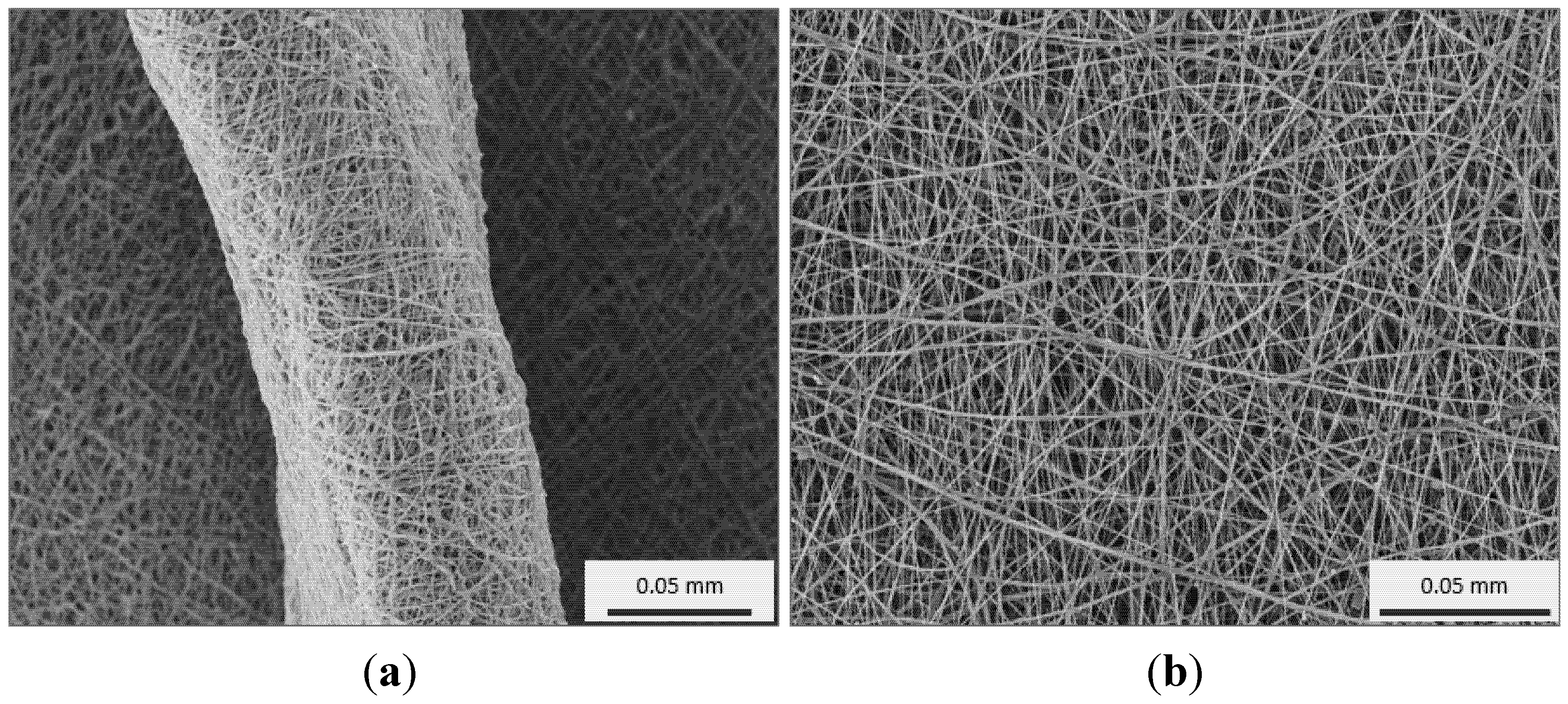
3.4. Electrospinning
| Graft Type | Compliance (% mmHg × 10−2) | Structure | Patency % (30/180 days) | Patency % (1/2 years) |
|---|---|---|---|---|
| Human femoral artery | 5.9 | – | – | – |
| Saphenous vein | 4.4 | Natural tissue | 94/93 | 88/84 |
| Umbilical vein | 3.7 | Natural tissue | 97/93 | 83/80 |
| PTFE | 1.6 | Extruded (non-textile) | 85/81 | 60/42 |
| Dacron® | 1.9 | Woven | 88/72 | 65/42 |

| Technique | Material | Scaffold Dimensions | Biological Response | Mechanical Testing | Ref. |
|---|---|---|---|---|---|
| Knitted | PET | 4 mm diameter | ECs: Better cell attachment was observed on precoated grafts in the following order: collagen (3.5 × 10⁵ cells/cm2) > fibrin (2.8 × 10⁵ cells/cm2) > fibronectin (2.4 × 10⁵ cells/cm2) > laminin = untreated (1.3 × 10⁵ cells/cm2) | – | [126] |
| Knitted | PET | 4 mm diameter cut into fusiform patches of 5 cm length × 8 mm width | In vivo: Implanted in sheep for 4 weeks and intimal hyperplasia assessed. Fluoropolymer coated PET sealed with gelatin produced the least amount of hyperplasia followed by PTFE, carbonlined PTFE and gelatin sealed PET | – | [127] |
| Knitted | PET | – | In vivo: Randomised clinical trial of 209 patients (femoropopliteal bypass). Patency at 3 years of collagen-coated heparin bonded PET (54%) was better than PTFE (44%). No difference in patency at 5 years between PET and PTFE | – | [128] |
| Woven and Electrospinning | PET and PU | Flat | In vitro (HUVECs): All 3 materials showed better cell attachment when coated with Collagen Type I/III as compared to their uncoated counterparts. Cell coverage on coated PTFE (34.6%) > PET (19.6%) > PU (17.5%); When exposed to shear stress of 1 Pa for 1 h, cell retention was highest on coated PTFE. No difference was observed across the 3 materials when shear stress increased to 2 Pa | – | [129] |
| Electrospinning | PCL and PU | NS | In vitro (HUVECs): Good cell attachment (~ 61%). Cells produced proteins such as PECAM and vWF, indicating normal phenotype and function | – | [130] |
| Electrospinning | Silk fibroin | 1.5 mm diameter | In vivo: Implanted in rats for 7 days to 6 months. No graft degradation or foreign body reaction observed. 95% of grafts remained unblocked. After 1 month implantation, ECs were observed on the luminal surface of the grafts. Cell coverage continue to increase at 6 months | – | [131] |
| Electrospinning | Silk | 5 mm diameter | In vitro: ECs and SMCs attached and proliferated on the scaffold. ECs were observed on the surface of the scaffold while SMCs migrated into the scaffold | Tensile strength: 2.42 MPa; Elastic modulus: 2.45 MPa; Mean burst pressure: 811 mmHg | [132] |
| Electrospinning | PCL | 2 mm diameter | In vivo: Implanted in rats for 24 weeks. No narrowing of the grafts (stenosis) in the PCL group. ECs coverage confluent at 12 weeks in the PCL group vs. ePTFE group (incomplete at 24 weeks). | – | [133] |
| Electrospinning | PCL | NS | In vitro: A confluent layer of oriented SMCs in the direction of aligned fibres after 7 days culture | – | [134] |
| Electrospinning | Collagen Type 1, elastin and PLGA | Tubular (4.75 mm diameter, 12 cm long) | In vitro: Mean of 72% for ECs and 82% for SMCs viability over 7-day culture period; In vivo (mice): No systemic or neurological toxicity, normal blood count, transient local inflammation at implantation site | Burst pressure: 1425 mm Hg; Compliance: 12%–14% for scaffold vs. 9% for native vessel; Maximal axial and circumferential strain: 40% strain | [119] |
| Electrospinning | Collagen and PCL | Tubular (4.75 mm diameter, 12 cm long) | ECs: Cytoskeletal organisation and focal adhesion via actin and vinculin staining respectively were better developed when cultured on smaller sized fibres; SMCs: Infiltration of cells into scaffolds with fibres > 1 µm in diameter during a 4-week culture | Tensile strength: Increasing fibre diameter (0.27 µm to 4.45 µm) decreased tensile strength from 3.15 MPa to 0.75 MPa; Elongation at break: Increased with increasing fibre diameter (90% for 0.27 µm fibres to 734% for 4.45 µm fibres); Maximum load: Decreased from 25.75 N (0.27 µm fibres) to 8.63 N (4.45 µm fibres) | [135] |
| Knitting | Elastin solubilised proteins and PET | Flat | HUVECs: No cytotoxicity, 43% cell attachment for elastin solubilised protein-PET vs. 94% for PET | – | [136] |
| Electrospinning | Elastin and PDO | 6 mm diameter | In vitro: Fibroblasts cultured for 7 days on PDO:Elastin graft showed migration into the fibrous materials vs. no migration in PDO graft | PDO:Elastin ratio of 50:50 produced compliance that mimics native femoral artery | [137] |
| Electrospinning | PCL, PDO and Silk | NS | In vitro: Risk of clotting using human monocytes – PCL < Silk < PDO. The risk in PCL is comparable to ePTFE (currently used grafts in clinics) | – | [138] |
| Electrospinning | Chitosan and PVA | NS | In vitro: Good fibroblast growth was observed with continual proliferation up to 21 days | – | [139] |
4. Discussion
| Structure | Material | Trade Name | Special Design Feature | Intended Improvement | Manufa-cturer | Application Area |
|---|---|---|---|---|---|---|
| Woven | Dacron® & PTFE | FUSION BIOLINE® | Two layer, Heparin coated | Improves patency and healing response | Macquet | Peripheral |
| Dacron® | HEMASHIELD® PLATINUM | Multiple branched, Double velour, Collagen coated | Enhances healing response | Aortic | ||
| VASCUTEK® GELWEAVE™ Pre-curved | Pre-curved design | Matches aortic arch anatomy | Terumo | |||
| VASCUTEK® SIENA™ | Extended trunk and collar design | Suits hybrid surgery procedures | ||||
| VASCUTEK® GELWEAVE™ Plexus | Multiple branched, Gelatin impregnated | Suits complete aortic arch surgery | ||||
| VASCUTEK® GELWEAVE™ Valsalva | Extended skirt design | Matches aortic root anatomy | ||||
| VASCUTEK® GELWEAVE™ Ante-Flo | Extra branch | Reduces surgery time, Lowers risk of neurological deficits | ||||
| E-VITA™ OPEN PLUS | Extended stented trunk | Suits hybrid surgery procedures | Jotec | |||
| Knitted | INTEGRAD® SILVER | Silver impregnated | Reduces graft infection | Macquet | Aortic, Peripheral | |
| HEMAGARD® Ultrathin | Collagen coated, Wall thickness = 0.35 mm | Improves healing response, Reduces dilatation, Increases suture strength | Aortic | |||
| HEMASHIELD® GOLD | Collagen coated, Double velour surface | Improves healing response, Reduces dilatation, Increases suture strength | ||||
| VASCUTEK® GELSEAL™ | Gelatin impregnated | Improves healing | Terumo | Aortic, Peripheral | ||
| VASCUTEK® GELSOFT™ ERS | Gelatin impregnated, Radially supported | Improves healing and handling | ||||
| FLOWNIT BIOSEAL® | Texturised yarn, Collagen impregnated | Low dilatation, Enhances tissue incorporation | Jotec | Aortic |
5. Conclusions
Author Contributions
Conflicts of Interest
References
- Roach, M.R.; Burton, A.C. The reason for the shape of the distensibility curves of arteries. Can. J. Biochem. Physiol. 1957, 35, 681–690. [Google Scholar] [CrossRef] [PubMed]
- Shadwick, R.E. Elasticity in Arteries. Am. Sci. 1998, 86, 535–541. [Google Scholar] [CrossRef]
- Shadwick, R.E. Mechanical design in arteries. J. Exp. Biol. 1999, 202, 3305–3313. [Google Scholar] [PubMed]
- Abbott, W.M.; Megerman, J.; Hasson, J.E.; L’Italien, G.; Warnock, D.F. Effect of compliance mismatch on vascular graft patency. J. Vasc. Surg. 1987, 5, 376–382. [Google Scholar] [CrossRef]
- Weston, M.W.; Rhee, K.; Tarbell, J.M. Compliance and diameter mismatch affect the wall shear rate distribution near an end-to-end anastomosis. J. Biomech. 1996, 29, 187–198. [Google Scholar] [CrossRef]
- Chlupác, J.; Filová, E.; Bačáková, L. Blood vessel replacement: 50 years of development and tissue engineering paradigms in vascular surgery. Physiol. Res. 2009, 58, 119–140. [Google Scholar]
- Kannan, R.Y.; Salacinski, H.J.; Butler, P.E.; Hamilton, G.; Seifalian, A.M. Current status of prosthetic bypass grafts: A review. J. Biomed. Mater. Res. B. 2005, 74, 570–581. [Google Scholar] [CrossRef] [PubMed]
- Salacinski, H.J.; Goldner, S.; Giudiceandrea, A.; Hamilton, G.; Seifalian, A.M.; Edwards, A.; Carson, R.J. The mechanical behavior of vascular grafts: A review. J. Biomater. Appl. 2001, 15, 241–278. [Google Scholar] [CrossRef] [PubMed]
- Pourdeyhimi, B.; Text, C. A review of structural and material properties of vascular grafts. J. Biomater. Appl. 1987, 2, 163–204. [Google Scholar] [CrossRef] [PubMed]
- Pourdeyhimi, B.; Wagner, D. On the correlation between the failure of vascular grafts and their structural and material properties: A critical analysis. J. Biomed. Mater. Res. 1986, 20, 375–409. [Google Scholar] [CrossRef] [PubMed]
- Silver, F.; Snowhill, P.; Foran, D. Mechanical behavior of vessel wall: A comparative study of aorta, vena cava, and carotid artery. Ann. Biomed. Eng. 2003, 31, 793–803. [Google Scholar] [CrossRef] [PubMed]
- Fischer, G.M.; Llaurado, J.G. Collagen and elastin content in canine arteries selected from functionally different vascular beds. Circ. Res. 1966, 19, 394–399. [Google Scholar] [CrossRef] [PubMed]
- Kassab, G.S. Biomechanics of the cardiovascular system: The aorta as an illustratory example. J. R. Soc. Interface 2006, 3, 719–740. [Google Scholar] [CrossRef] [PubMed]
- Belz, G.G. Elastic properties and Windkessel function of the human aorta. Cardiovasc. Drugs Ther. 1995, 9, 73–83. [Google Scholar] [CrossRef] [PubMed]
- Greenfield, J.C.; Patel, D.J. Relation between pressure and diameter in the ascending aorta of man. Circ. Res. 1962, 10, 778–781. [Google Scholar] [CrossRef] [PubMed]
- Lillie, M.A.; Shadwick, R.E.; Gosline, J.M. Mechanical anisotropy of inflated elastic tissue from the pig aorta. J. Biomech. 2010, 43, 2070–2078. [Google Scholar] [CrossRef] [PubMed]
- Zhang, W.; Liu, Y.; Kassab, G.S. Viscoelasticity reduces the dynamic stresses and strains in the vessel wall: Implications for vessel fatigue. Am. J. Physiol. 2007, 293, H2355–H2360. [Google Scholar] [CrossRef] [PubMed]
- Blakemore, A.H.; Voorhees, A.B. The use of tubes constructed from vinyon “N” cloth in bridging arterial defects—Experimental and clinical. Ann. Surg. 1954, 140, 324–333. [Google Scholar] [CrossRef] [PubMed]
- Voorhees, A.B.J.; Jaretzki, A.I.; Blakemore, A.H. The use of tubes constructed from Vinyon “N” cloth in bridging arterial defects: A preliminary report. Ann. Surg. 1952, 135, 332–336. [Google Scholar] [CrossRef] [PubMed]
- Harris, E.J.; Shumacker, H.B., Jr.; Siderys, H.; Moore, T.C.; Grice, P.F. Pliable plastic aortic grafts: Experimental comparison of a number of materials. AMA Arch. Surg. 1955, 71, 449–459. [Google Scholar] [CrossRef] [PubMed]
- Hufnagel, C.A.; Rabil, P. Replacement of arterial segments, utilizing flexible orlon prostheses. AMA Arch. Surg. 1955, 70, 105–110. [Google Scholar] [CrossRef] [PubMed]
- Deterling, R.A., Jr.; Bhonslay, S.B. Use of vessel grafts and plastic prostheses for relief of superior vena caval obstruction. Surgery. 1955, 38, 1008–1026. [Google Scholar] [PubMed]
- Harrison, J.H. Synthetic materials as vascular prostheses. I. A comparative study in small vessels of nylon, dacron, orlon, ivalon sponge and teflon. Am. J. Surg. 1958, 95, 3–15. [Google Scholar] [CrossRef]
- Julian, O.C.; Deterling, R.A., Jr.; Su, H.H.; Dye, W.S.; Belio, M.L. Dacron tube and bifurcation arterial prostheses produced to specification. Experimental and clinical use. Surgery 1957, 41, 50–61. [Google Scholar]
- Knox, G.; Begg, C.F. Evaluation of the need for porosity in synthetic arterial prostheses. A case report and evaluation of dacron aortic grafts in dogs. Surgery 1957, 42, 922–927. [Google Scholar] [PubMed]
- Harrison, J.H. Synthetic materials as vascular prostheses: II. A comparative study of nylon, dacron, orlon, ivalon sponge and teflon in large blood vessels with tensile strength studies. Am. J. Surg. 1958, 95, 16–24. [Google Scholar] [CrossRef]
- Tremblay, D.; Zigras, T.; Cartier, R.; Leduc, L.; Butany, J.; Mongrain, R.; Leask, R.L. A comparison of mechanical properties of materials used in aortic arch reconstruction. Ann. Thorac. Surg. 2009, 88, 1484–1491. [Google Scholar] [CrossRef] [PubMed]
- Lantelme, P.; Dzudie, A.; Milon, H.; Bricca, G.; Legedz, L.; Chevalier, J.M.; Feugier, P. Effect of abdominal aortic grafts on aortic stiffness and central hemodynamics. J. Hypertens. 2009, 27, 1268–1276. [Google Scholar] [CrossRef] [PubMed]
- Kim, S.Y.; Hinkamp, T.J.; Jacobs, W.R.; Lichtenberg, R.C.; Posniak, H.; Pifarré, R. Effect of an inelastic aortic synthetic vascular graft on exercise hemodynamics. Ann. Thorac. Surg. 1995, 59, 981–989. [Google Scholar] [CrossRef]
- Obrien, T.; Morris, L.; McGloughlin, T. Evidence suggests rigid aortic grafts increase systolic blood pressure: Results of a preliminary study. Med. Eng. Phys. 2008, 30, 109–115. [Google Scholar] [CrossRef] [PubMed]
- Fung, Y.C. Biomechanics: Mechanical Properties of Living Tissues; Springer: New York, NY, USA, 2013. [Google Scholar]
- Tai, N.R.; Salacinski, H.J.; Edwards, A.; Hamilton, G.; Seifalian, A.M. Compliance properties of conduits used in vascular reconstruction. Br. J. Surg. 2000, 87, 1516–1524. [Google Scholar] [CrossRef] [PubMed]
- Kidson, I.G. The effect of wall mechanical properties on patency of arterial grafts. Ann. R. Coll. Surg. Engl. 1983, 65, 24–29. [Google Scholar] [PubMed]
- Anderson, K.; Seyam, A. Developing seamless shaped woven medical products. J. Med. Eng. Technol. 2004, 28, 110–116. [Google Scholar] [CrossRef] [PubMed]
- Kotsuka, Y.; Ezure, M.; Tanaka, K.; Takamoto, S.; Kuwahara, K.; Ikeda, H. Ultrathin-wall vascular grafts for endovascular surgery. J. Artif. Organs 2002, 5, 108–112. [Google Scholar] [CrossRef]
- De Paulis, R.; Scaffa, R.; Maselli, D.; Salica, A.; Bellisario, A.; Weltert, L. A third generation of ascending aorta dacron graft: Preliminary experience. Ann. Thorac. Surg. 2008, 85, 305–309. [Google Scholar]
- Abdessalem, S.B.; Durand, B.; Akesbi, S.; Chakfe, N. Blood flow in a polyester textile vascular prosthesis: Experimental and numerical study. Text. Res. J. 2001, 71, 178–183. [Google Scholar] [CrossRef]
- Hajjaji, R.; Abdessalem, S.B.; Ganghoffer, J.F. The influence of textile vascular prosthesis crimping on graft longitudinal elasticity and flexibility. J. Mech. Behav. Biomed. Mat. 2012, 16, 73–80. [Google Scholar] [CrossRef] [PubMed]
- Moghe, A.K.; Gupta, B.S. Small-diameter blood vessels by weaving: Prototyping and modelling. J. Text. Inst. 2008, 99, 467–477. [Google Scholar] [CrossRef]
- Hasegawa, M.; Azuma, T. Mechanical properties of synthetic arterial grafts. J. Biomech. 1979, 12, 509–517. [Google Scholar] [CrossRef]
- Wagner, M.; Reul, G.; Teresi, J.; Kayser, K.L. Experimental observations on a new and inherently elastic material for sutures and vascular prostheses: Lycra. Am. J. Sur. 1966, 111, 838–841. [Google Scholar] [CrossRef]
- Szilagyi, D.; France, L.C.; Smith, R.F.; Whitcomb, J.G. The clinical use of an elastic dacron prosthesis. AMA Arch. Surg. 1958, 77, 538–551. [Google Scholar] [CrossRef] [PubMed]
- Szilagyi, D.; Whitcomb, J.G.; Shonnard, C.P. Replacement of long and narrow arterial segments: II. Experimental studies with an elastic (“Helanca”) seamless woven nylon prosthesis. AMA Arch. Surg. 1957, 74, 944–953. [Google Scholar] [CrossRef] [PubMed]
- Gupta, B.S.; Kasyanov, V.A. Biomechanics of human common carotid artery and design of novel hybrid textile compliant vascular grafts. J. Biomed. Mater. Res. 1997, 34, 341–349. [Google Scholar] [CrossRef]
- Rosenberg, N.; Simpson, A.N.; Brown, R.E. A circumferentially elastic arterial prosthesis: Three-year studies of a dacron-spandex graft in the dog. J. Surg. Res. 1983, 34, 7–16. [Google Scholar] [CrossRef]
- Chen, Y.; Ding, X.; Li, Y.; King, M.W.; Gao, J.; Zhao, X. A bilayer prototype woven vascular prosthesis with improved radial compliance. J. Text. Inst. 2011, 103, 106–111. [Google Scholar] [CrossRef]
- Sonoda, H.; Takamizawa, K.; Nakayama, Y.; Yasui, H.; Matsuda, T. Small-diameter compliant arterial graft prosthesis: Design concept of coaxial double tubular graft and its fabrication. J. Biomed. Mater. Res. 2001, 55, 266–276. [Google Scholar] [CrossRef]
- Sanger, P.W.; Taylor, F.H.; McCall, R.E.; Duchesne, R.; Lepage, G. Seamless synthetic arterial grafts; preliminary report on experimental and clinical experiences. J. Am. Med. Assoc. 1956, 160, 1403–1404. [Google Scholar] [PubMed]
- De Bakey, M.; Cooley, D.A. Successful resection of aneurysm of distal aortic arch and replacement by graft. J. Am. Med. Assoc. 1954, 155, 1398–1403. [Google Scholar]
- De Bakey, M.E.; Cooley, D.A.; Crawford, E.; Morris, G.C., Jr. Clinical application of a new flexible knitted dacron arterial substitute. AMA Arch. Surg. 1958, 77, 713–724. [Google Scholar]
- Chakfe, N.; Dieval, F.; Wang, L.; Thaveau, F.; Rinckenbach, S.; Edah-Tally, S.; Mathieu, D.; Le Magnen, J.F.; Riepe, G.; Kretz, J.G.; Durand, B. In vitro approach to the dilative behavior of knitted vascular prosthetic grafts. Ann. Vasc. Surg. 2008, 22, 402–411. [Google Scholar] [CrossRef] [PubMed]
- Chakfé, N.; Riepe, G.; Dieval, F.; Le Magnen, J.F.; Wang, L.; Urban, E.; Beaufigeau, M.; Durand, B.; Imig, H.; Kretz, J.G. Longitudinal ruptures of polyester knitted vascular prostheses. J. Vasc. Surg. 2001, 33, 1015–1021. [Google Scholar] [CrossRef] [PubMed]
- Dieval, F.; Chakfé, N.; Wang, L.; Riepe, G.; Thaveau, F.; Heintz, C.; Mathieu, D.; Le Magnen, J.F.; Kretz, J.G.; Durand, B. Mechanisms of rupture of knitted polyester vascular prostheses: An in vitro analysis of virgin prostheses. Eur. J. Vasc. Endovasc. Surg. 2003, 26, 429–436. [Google Scholar] [CrossRef]
- Ichikawa, H.; Ishikawa, S.; Ohtaki, A.; Otani, Y.; Sakata, K.; Takahashi, T.; Aizaki, M.; Sato, Y.; Morishita, Y. Clinical experience with a knitted Dacron graft impregnated with gelatin (Gelseal Triaxial®). Artif. Organs 1996, 5, 59–63. [Google Scholar]
- Kudo, F.A.; Nishibe, T.; Miyazaki, K.; Flores, J.; Yasuda, K. Albumin-coated knitted Dacron aortic prostheses. Study of prosperative inflammatory reactions. Int. Angiol. 2002, 21, 214–217. [Google Scholar] [PubMed]
- Marais, Y.; Guidoin, R.; Deng, X.; King, M.W.; Martin, L.; Roy, R. The Dialine II graft: A new collagen-impregnated warp-knitted polyester arterial prosthesis. Ann. Vasc. Surg. 1997, 11, 133–140. [Google Scholar] [CrossRef] [PubMed]
- Mary, C.; Marois, Y.; King, M.W.; Hong, T.; Laroche, G.; Douville, Y.; Martin, L.; Guidoin, R. In vitro and in vivo studies of a polyester arterial prosthesis with a warp-knitted sharkskin structure. J. Biomed. Mater. Res. 1997, 35, 459–472. [Google Scholar] [CrossRef]
- Meister, R.H.; Schweiger, H.; Lang, W. Knitted double-velour Dacron prostheses in aortobifemoral position—Long-term performance of different coating materials. Vasa J. Vasc. Disease. 1998, 27, 236–239. [Google Scholar]
- Phaneuf, M.D.; Dempsey, D.J.; Bide, M.J.; Quist, W.C.; LoGerfo, F.W. Coating of Dacron vascular grafts with an ionic polyurethane: a novel sealant with protein binding properties. Biomaterials 2001, 22, 463–469. [Google Scholar] [CrossRef]
- Sirry, M.S.; Zilla, P.; Franz, T. A computational study of structural designs for a small-diameter composite vascular graft promoting tissue regeneration. Cardiovasc. Eng. Technol. 2010, 1, 269–281. [Google Scholar] [CrossRef]
- Wang, F.J.; Mohammed, A.; Li, C.J.; Wang, L. Promising poly(ε-caprolactone) composite reinforced with weft-knitted polyester for small-diameter vascular graft application. Adv. Mater. Sci. Eng. 2014, 2014, 1–9. [Google Scholar] [CrossRef]
- Xu, W.; Zhou, F.; Ouyang, C.; Ye, W.; Yao, M.; Xu, B. Mechanical properties of small-diameter polyurethane vascular grafts reinforced by weft-knitted tubular fabric. J. Biomed. Mater. Res. 2010, 92, 1–8. [Google Scholar] [CrossRef] [PubMed]
- Yagi, T.; Sato, M.; Nakazawa, Y.; Tanaka, K.; Sata, M.; Itoh, K.; Takagi, Y.; Asakura, T. Preparation of double-raschel knitted silk vascular grafts and evaluation of short-term function in a rat abdominal aorta. J. Artif. Organs 2011, 14, 89–99. [Google Scholar] [CrossRef] [PubMed]
- Yang, H.; Zhu, G.; Zhang, Z.; Wang, Z.; Fang, J.; Xu, W. Influence of weft-knitted tubular fabric on radial mechanical property of coaxial three-layer small-diameter vascular graft. J. Biomed. Mater. Res. B 2012, 100, 342–349. [Google Scholar] [CrossRef] [PubMed]
- Freitas, A.F.D.P.; de Araujo, M.D.; Zu, W.W.; Fangueiro, R.M.E. Development of weft-knitted and braided polypropylene stents for arterial implant. J. Text. Inst. 2010, 101, 1027–1034. [Google Scholar] [CrossRef] [Green Version]
- Li, G.; Li, Y.; Lan, P.; He, X.; Hu, H. Polydioxanone weft-knitted intestinal stents: fabrication and mechanics optimization. Text. Res. J. 2013, 83, 2129–2141. [Google Scholar] [CrossRef]
- Moodley, L.; Franz, T.; Human, P.; Wolf, M.F.; Bezuidenhout, D.; Scherman, J.; Zilla, P. Protective constriction of coronary vein grafts with knitted nitinol. Eur. J. Cardiothorac. Surg. 2013, 44, 64–71. [Google Scholar] [CrossRef] [PubMed]
- Weinandy, S.; Rongen, L.; Schreiber, F.; Cornelissen, C.; Flanagan, T.C.; Mahnken, A.; Gries, T.; Schmitz-Rode, T.; Jockenhoevel, S. The BioStent: Novel concept for a viable stent structure. Tissue Eng. A 2012, 18, 1818–1826. [Google Scholar] [CrossRef] [PubMed]
- Zilla, P.; Moodley, L.; Wolf, M.F.; Bezuidenhout, D.; Sirry, M.S.; Rafiee, N.; Lichtenberg, W.; Black, M.; Franz, T. Knitted nitinol represents a new generation of constrictive external vein graft meshes. J. Vasc. Surg. 2011, 54, 1439–1450. [Google Scholar] [CrossRef] [PubMed]
- Singh, C.; Wang, X. A biomimetic approach for designing stent-graft structures: Caterpillar cuticle as design model. J. Mech. Behav. Biomed. Mater. 2014, 30, 16–29. [Google Scholar] [CrossRef] [PubMed]
- Singh, C.; Wang, X. A new design concept for knitted external vein-graft support mesh. J. Mech. Behav. Biomed. Mater. 2015, 48, 125–133. [Google Scholar] [CrossRef] [PubMed]
- Self, M.M.; Cooley, D.A.; Debakey, M.E.; Creech, O., Jr. The use of braided nylon tubes for aortic replacement. Ann. Surg. 1955, 142, 836–843. [Google Scholar] [CrossRef] [PubMed]
- Edwards, W.S.; Tapp, J.S. Braided textiles tubes as arterial grafts. Surgery 1995, 38, 61–67. [Google Scholar]
- Dale, W.; Niguidula, F.N. Study of elasticized dacron as arterial prosthesis: Experimental comparison with other plastics, homologous arteries, and autogenous veins. AMA Arch. Surg. 1959, 78, 246–259. [Google Scholar] [CrossRef] [PubMed]
- Whittlesey, R.H.; Sekerak, N.M.; Blunt, J.W., Jr.; Hudack, S.S. Observations of elastic synthetic fabric sleeves as vascular prostheses. AMA Arch. Surg. 1956, 73, 440–454. [Google Scholar] [CrossRef]
- Parodi, J.C.; Palmaz, J.C.; Barone, H.D. Transfemoral intraluminal graft implantation for abdominal aortic aneurysms. Ann. Vasc. Surg. 1991, 5, 491–499. [Google Scholar] [CrossRef] [PubMed]
- Wilson, G.; Klement, P.; Kato, Y.P.; Martin, J.B.; Khan, I.J.; Alcime, R.; Dereume, J.-P.; Macgregor, D.C.; Pinchuk, L. A self-expanding bifurcated endovascular graft for abdominal Aortic aneurysm repair an initial study in a canine model. ASAIO J. 1996, 42, M386–M393. [Google Scholar] [CrossRef] [PubMed]
- Georg, Y.; Settembre, N.; Marchand, C.; Lejay, A.; Thaveau, F.; Durand, B.; Chakfe, N. Poor long-term stability of the Corvita abdominal stentgraft. Eur. J. Vasc. Endovasc. Surg. 2014, 47, 160–163. [Google Scholar] [CrossRef] [PubMed]
- Raillat, C.; Rousseau, H.; Joffre, F.; Roux, D. Treatment of iliac artery stenoses with the Wallstent endoprosthesis. Am. J. Roentgenol. 1990, 154, 613–616. [Google Scholar] [CrossRef] [PubMed]
- Kallmes, D.F.; Ding, Y.H.; Dai, D.; Kadirvel, R.; Lewis, D.A.; Cloft, H.J. A new endoluminal, flow-disrupting device for treatment of saccular aneurysms. Stroke 2007, 38, 2346–2352. [Google Scholar] [CrossRef] [PubMed]
- Kallmes, D.F.; Ding, Y.H.; Dai, D.; Kadirvel, R.; Lewis, D.A.; Cloft, H.J. A Second-Generation, Endoluminal, Flow-Disrupting Device for Treatment of Saccular Aneurysms. Am. J. Neuroradiol. 2009, 30, 1153–1158. [Google Scholar] [CrossRef] [PubMed]
- Lieber, B.; Stancampiano, A.; Wakhloo, A. Alteration of hemodynamics in aneurysm models by stenting: Influence of stent porosity. Ann. Biomed. Eng. 1997, 25, 460–469. [Google Scholar] [CrossRef] [PubMed]
- Mallik, A.S.; Nuss, K.; Kronen, P.W.; Klein, K.; Karol, A.; von Rechenberg, B.; Rüfenacht, D.A.; Wanke, I.; Kulcsár, Z. A new-generation, low-permeability flow diverting device for treatment of saccular aneurysms. Eur. Radiol. 2014, 24, 12–18. [Google Scholar] [CrossRef] [PubMed]
- Alderson, H.; Zamir, M. Effects of stent stiffness on local haemodynamics with particular reference to wave reflections. J. Biomech. 2004, 37, 339–348. [Google Scholar] [CrossRef]
- Nii, K.; Tsutsumi, M.; Aikawa, H.; Hamaguchi, S.; Etou, H.; Sakamoto, K.; Kazekawa, K. Incidence of hemodynamic depression after carotid artery stenting using different self-expandable stent types. Neurol. Med. Chir. 2011, 51, 556–560. [Google Scholar] [CrossRef]
- Tanaka, N.; Martin, J.B.; Tokunaga, K.; Abe, T.; Uchiyama, Y.; Hayabuchi, N.; Berkefeld, J.; Rüfenacht, D.A. Conformity of carotid stents with vascular anatomy: Evaluation in carotid Models. Am. J. Neuroradiol. 2004, 25, 604–607. [Google Scholar] [PubMed]
- Hyun Kim, J.; Jin Kang, T.; Yu, W.-R. Simulation of mechanical behavior of temperature-responsive braided stents made of shape memory polyurethanes. J. Biomech. 2010, 43, 632–643. [Google Scholar] [CrossRef] [PubMed]
- Irsale, S.; Adanur, S. Design and characterization of polymeric stents. J. Ind. Text. 2006, 35, 189–200. [Google Scholar] [CrossRef]
- Lin, J.H.; Wen, S.P.; Lou, C.W.; Ueng, K.C. Compression behaviors of stainless steel braided coronary stents and polyvinyl alcohol/stainless steel braided coronary stents. Adv. Mater. Res. 2014, 910, 274–278. [Google Scholar] [CrossRef]
- Mikkonen, J.; Uurto, I.; Isotalo, T.; Kotsar, A.; Tammela, T.L.J.; Talja, M.; Salenius, J.P.; Törmälä, P.; Kellomäki, M. Drug-eluting bioabsorbable stents—An in vitro study. Acta Biomater. 2009, 5, 2894–2900. [Google Scholar] [CrossRef] [PubMed]
- Nuutinen, J.P.; Välimaa, T.; Clerc, C.; Törmälä, P. Mechanical properties and in vitro degradation of bioresorbable knitted stents. J. Biomater. Sci. Polym. Ed. 2002, 13, 1313–1323. [Google Scholar] [CrossRef] [PubMed]
- Rebelo, R.; Vila, N.; Fangueiro, R.; Carvalho, S.; Henriques, M. Development of braided fiber-based stents. Stud. Health Technol. Inform. 2014, 207, 135–144. [Google Scholar] [PubMed]
- Ueng, K.-C.; Wen, S.-P.; Lou, C.-W.; Lin, J.-H. Braiding structure stability and section treatment evaluations of braided coronary stents made of stainless steel and bio-absorbable polyvinyl alcohol via a braiding technique. Fib. Polym. 2015, 16, 675–684. [Google Scholar] [CrossRef]
- van der Giessen, W.J.; Slager, C.J.; Van Beusekom, H.M.M.; Van Ingen Schenau, D.S.; Huijts, R.A.; Schuurbiers, J.C.; de Klein, W.J.; Serruys, P.W.; Verdouw, P.D. Development of a Polymer endovascular prosthesis and its implantation in porcine arteries. J. Interv. Cardiol. 1992, 5, 175–186. [Google Scholar]
- Wang, X.; Li, Q.; Hu, X.; Ma, L.; You, C.; Zheng, Y.; Sun, H.; Han, C.; Gao, C. Fabrication and characterization of poly(L-lactide-co-glycolide) knitted mesh-reinforced collagen-chitosan hybrid scaffolds for dermal tissue engineering. J. Mech. Behav. Biomed. Mater. 2012, 8, 204–215. [Google Scholar] [CrossRef] [PubMed]
- Yuksekkaya, M.E.; Adanur, S. Analysis of polymeric braided tubular structures intended for medical applications. Text. Res. J. 2009, 79, 99–109. [Google Scholar] [CrossRef]
- De Beule, M.; Van Cauter, S.; Mortier, P.; Van Loo, D.; Van Impe, R.; Verdonck, P.; Verhegghe, B. Virtual optimization of self-expandable braided wire stents. Med. Eng. Phys. 2009, 31, 448–453. [Google Scholar] [CrossRef] [PubMed]
- Kim, J.H.; Kang, T.J.; Yu, W.R. Mechanical modeling of self-expandable stent fabricated using braiding technology. J. Biomech. 2008, 41, 3202–3212. [Google Scholar] [CrossRef] [PubMed]
- Makoyeva, A.; Bing, F.; Darsaut, T.E.; Salazkin, I.; Raymond, J. The varying porosity of braided self-expanding stents and flow diverters: An experimental study. Am. J. Neuroradiol. 2013, 34, 596–602. [Google Scholar] [CrossRef] [PubMed]
- Sui, W.; Jiang, J.; Chen, N. Effects of braiding parameters on radial compressive property of intraluminal stents. Appl. Mech. Mater. 2013, 268, 213–216. [Google Scholar] [CrossRef]
- Balderi, A.; Antonietti, A.; Pedrazzini, F.; Ferro, L.; Leotta, L.; Peano, E.; Grosso, M. Treatment of a hepatic artery aneurysm by endovascular exclusion using the multilayer cardiatis stent. Cardiovasc. Intervent. Radiol. 2010, 33, 1282–1286. [Google Scholar] [CrossRef] [PubMed]
- Henry, M.; Polydorou, A.; Frid, N.; Gruffaz, P.; Cavet, A.; Henry, I.; Hugel, M.; Rüfenacht, D.A.; Augsburger, L.; De Beule, M.; et al. Treatment of renal artery aneurysm with the multilayer stent. J. Endovasc. Ther. 2008, 15, 231–236. [Google Scholar] [CrossRef] [PubMed]
- Müller-Eschner, M.; Kortes, N.; Rehnitz, C.; Sumkauskaite, M.; Rengier, F.; Böckler, D.; Kauczor, H.-U.; Radeleff, B. Endovascular repair of a complex splenic artery aneurysm using a multilayer stent. Cardiovasc. Intervent. Radiol. 2015, 38, 494–497. [Google Scholar] [CrossRef] [PubMed]
- Ahlhelm, F.; Kaufmann, R.; Ahlhelm, D.; Ong, M.; Roth, C.; Reith, W. Carotid artery stenting using a novel self-expanding braided nickel–titanium stent: Feasibility and safety porcine trial. Cardiovasc. Intervent. Radiol. 2009, 32, 1019–1027. [Google Scholar] [CrossRef] [PubMed]
- Ahlhelm, F.; Roth, C.; Kaufmann, R.; Schulte-Altedorneburg, G.; Romeike, B.M.; Reith, W. Treatment of wide-necked intracranial aneurysms with a novel self-expanding two-zonal endovascular stent device. Neuroradiology 2007, 49, 1023–1028. [Google Scholar] [CrossRef] [PubMed]
- Marchand, C.; Heim, F.; Durand, B.; Chafke, N. Nitinol stent for percutaneous heart valve implantation: Material shape setting. Mater. Manuf. Process. 2011, 26, 181–187. [Google Scholar] [CrossRef]
- Massell, T.B.; Heringman, E.; Greenstone, S.M. Woven Dacron and woven Teflon prostheses: Use for small artery replacement. Arch. Surg. 1962, 84, 73–79. [Google Scholar] [CrossRef] [PubMed]
- Cate, W.R., Jr. Bypass grafts in small arteries: An experimental comparison of freeze-dried arterial homografts, autogenous vein and crimped dacron. Am. Surg. 1959, 25, 523–527. [Google Scholar] [PubMed]
- Desai, M.; Seifalian, A.M.; Hamilton, G. Role of prosthetic conduits in coronary artery bypass grafting. Eur. J. Cardiothorac. Surg. 2011, 40, 394–398. [Google Scholar] [CrossRef] [PubMed]
- Seifalian, A.M.; Tiwari, A.; Hamilton, G.; Salacinski, H.J. Improving the clinical patency of prosthetic vascular and coronary bypass grafts: The role of seeding and tissue engineering. Artif. Organs. 2002, 26, 307–320. [Google Scholar] [CrossRef] [PubMed]
- Burkel, W.E.; Vinter, D.W.; Ford, J.W.; Kahn, R.H.; Graham, L.M.; Stanley, J.C. Sequential studies of healing in endothelial seeded vascular prostheses: Histologic and ultrastructure characteristics of graft incorporation. J. Surg. Res. 1981, 30, 305–324. [Google Scholar] [CrossRef]
- Fujita, Y.; Wu, M.H.D.; Ishida, A.; Shi, Q.; Walker, M.; Hammond, W.P.; Sauvage, L.R. Accelerated healing of Dacron grafts seeded by preclotting with autologous bone marrow blood. Ann. Vasc. Surg. 1999, 13, 402–412. [Google Scholar] [CrossRef] [PubMed]
- Pasquinelli, G.; Freyrie, A.; Preda, P.; Curti, T.; D’Addato, M.; Laschi, R. Healing of prosthetic arterial grafts. Scanning Microsc. 1990, 4, 351–362. [Google Scholar] [PubMed]
- Tolan, M.; Wells, F.; Kendall, S.; Large, S.; Wallwork, J. Clinical experience with a collagen impregnated woven Dacron graft. J. Cardiovasc. Surg. 1995, 36, 323–327. [Google Scholar]
- Walden, R.; L’Italien, G.J.; Megerman, J.; Abbott, W.M. Matched elastic properties and successful arterial grafting. Arch. Surg. 1980, 115, 1166–1169. [Google Scholar] [CrossRef] [PubMed]
- Li, W.-J.; Laurencin, C.T.; Caterson, E.J.; Tuan, R.S.; Ko, F.K. Electrospun nanofibrous structure: A novel scaffold for tissue engineering. J. Biomed. Mater. Res. 2002, 60, 613–621. [Google Scholar] [CrossRef] [PubMed]
- Xu, C.Y.; Inai, R.; Kotaki, M.; Ramakrishna, S. Aligned biodegradable nanofibrous structure: A potential scaffold for blood vessel engineering. Biomaterials. 2004, 25, 877–886. [Google Scholar] [CrossRef]
- Agarwal, S.; Wendorff, J.H.; Greiner, A. Use of electrospinning technique for biomedical applications. Polymer 2008, 49, 5603–5621. [Google Scholar] [CrossRef]
- Stitzel, J.; Liu, J.; Lee, S.J.; Komura, M.; Berry, J.; Soker, S.; Lim, G.; Van Dyke, M.; Czerw, R.; Yoo, J.J.; Atala, A. Controlled fabrication of a biological vascular substitute. Biomaterials 2006, 27, 1088–1094. [Google Scholar] [CrossRef] [PubMed]
- Buttafoco, L.; Kolkman, N.G.; Engbers-Buijtenhuijs, P.; Poot, A.A.; Dijkstra, P.J.; Vermes, I.; Feijen, J. Electrospinning of collagen and elastin for tissue engineering applications. Biomaterials 2006, 27, 724–734. [Google Scholar] [CrossRef] [PubMed]
- Wong, C.; Liu, X.; Xu, Z.; Lin, T.; Wang, X. Elastin and collagen enhances electrospun aligned polyurethane as scaffolds for vascular graft. J. Mater. Sci. Mater. Med. 2013, 24, 1865–1874. [Google Scholar] [CrossRef] [PubMed]
- McClure, M.J.; Simpson, D.G.; Bowlin, G.L. Tri-layered vascular grafts composed of polycaprolactone, elastin, collagen, and silk: Optimization of graft properties. J. Mech. Behav. Biomed. Mater. 2012, 10, 48–61. [Google Scholar] [CrossRef] [PubMed]
- McClure, M.J.; Sell, S.A.; Simpson, D.G.; Walpoth, B.H.; Bowlin, G.L. A three-layered electrospun matrix to mimic native arterial architecture using polycaprolactone, elastin, and collagen: A preliminary study. Acta Biomater. 2010, 6, 2422–2433. [Google Scholar] [CrossRef] [PubMed]
- Soletti, L.; Hong, Y.; Guan, J.; Stankus, J.J.; El-Kurdi, M.S.; Wagner, W.R.; Vorp, D.A. A bilayered elastomeric scaffold for tissue engineering of small diameter vascular grafts. Acta Biomater. 2010, 6, 110–122. [Google Scholar] [CrossRef] [PubMed]
- Bonani, W.; Maniglio, D.; Motta, A.; Tan, W.; Migliaresi, C. Biohybrid nanofiber constructs with anisotropic biomechanical properties. J. Biomed. Mater. Res. B 2011, 96, 276–286. [Google Scholar] [CrossRef] [PubMed]
- Anderson, J.S.; Price, T.M.; Hanson, S.R.; Harker, L.A. In vitro endothelialization of small-caliber vascular grafts. Surgery 1987, 101, 577–586. [Google Scholar] [PubMed]
- Ao, P.Y.; Hawthorne, W.J.; Vicaretti, M.; Fletcher, J.P. Development of intimal hyperplasia in six different vascular prostheses. Eur. J. Vasc. Endovasc. Surg. 2000, 20, 241–249. [Google Scholar] [CrossRef] [PubMed]
- Devine, C.; McCollum, C. Heparin-bonded Dacron or polytetrafluorethylene for femoropopliteal bypass: five-year results of a prospective randomized multicenter clinical trial. J. Vasc. Surg. 2004, 40, 924–931. [Google Scholar] [CrossRef] [PubMed]
- Feugier, P.; Black, R.A.; Hunt, J.A.; How, T.V. Attachment, morphology and adherence of human endothelial cells to vascular prosthesis materials under the action of shear stress. Biomaterials 2005, 26, 1457–1466. [Google Scholar] [CrossRef] [PubMed]
- Williamson, M.R.; Black, R.; Kielty, C. PCL-PU composite vascular scaffold production for vascular tissue engineering: attachment, proliferation and bioactivity of human vascular endothelial cells. Biomaterials 2006, 27, 3608–3616. [Google Scholar] [CrossRef] [PubMed]
- Bergmeister, H.; Grasl, C.; Walter, I.; Plasenzotti, R.; Stoiber, M.; Schreiber, C.; Losert, U.; Weigel, G.; Schima, H. Electrospun small-diameter polyurethane vascular grafts: ingrowth and differentiation of vascular-specific host cells. Artif. Organs 2012, 36, 54–61. [Google Scholar] [CrossRef] [PubMed]
- Soffer, L.; Wang, X.; Zhang, X.; Kluge, J.; Dorfmann, L.; Kaplan, D.L.; Leisk, G. Silk-based electrospun tubular scaffolds for tissue-engineered vascular grafts. J. Biomater. Sci. Polym. Ed. 2008, 19, 653–664. [Google Scholar] [CrossRef] [PubMed]
- Pektok, E.; Nottelet, B.; Tille, J.-C.; Gurny, R.; Kalangos, A.; Moeller, M.; Walpoth, B.H. Degradation and healing characteristics of small-diameter poly(ε-Caprolactone) vascular grafts in the rat systemic arterial circulation. Circulation 2008, 118, 2563–2570. [Google Scholar] [CrossRef] [PubMed]
- Zhu, Y.; Cao, Y.; Pan, J.; Liu, Y. Macro-alignment of electrospun fibers for vascular tissue engineering. J. Biomed. Mater. Res. B 2010, 92, 508–516. [Google Scholar] [CrossRef] [PubMed]
- Ju, Y.M.; Choi, J.S.; Atala, A.; Yoo, J.J.; Lee, S.J. Bilayered scaffold for engineering cellularized blood vessels. Biomaterials 2010, 31, 4313–4321. [Google Scholar] [CrossRef] [PubMed]
- Dutoya, S.; Verna, A.; Lefèbvre, F.; Rabaud, M. Elastin-derived protein coating onto poly(ethylene terephthalate). Technical, microstructural and biological studies. Biomaterials 2000, 21, 1521–1529. [Google Scholar] [CrossRef]
- Sell, S.A.; McClure, M.J.; Barnes, C.P.; Knapp, D.C.; Walpoth, B.H.; Simpson, D.G.; Bowlin, G.L. Electrospun polydioxanone-elastin blends: potential for bioresorbable vascular grafts. Biomed Mater. 2006, 1, 72–80. [Google Scholar] [CrossRef] [PubMed]
- Wolfe, P.S.; Madurantakam, P.; Garg, K.; Sell, S.A.; Beckman, M.J.; Bowlin, G.L. Evaluation of thrombogenic potential of electrospun bioresorbable vascular graft materials: Acute monocyte tissue factor expression. J. Biomed. Mater. Res. A 2010, 92, 1321–1328. [Google Scholar] [CrossRef] [PubMed]
- Liu, Y.; Xiang, K.; Chen, H.; Li, Y.; Hu, Q. Composite vascular repair grafts via micro-imprinting and electrospinning. AIP Adv. 2015, 5. [Google Scholar] [CrossRef]
© 2015 by the authors. Licensee MDPI, Basel, Switzerland. This article is an open access article distributed under the terms and conditions of the Creative Commons Attribution license ( http://creativecommons.org/licenses/by/4.0/).
Share and Cite
Singh, C.; Wong, C.S.; Wang, X. Medical Textiles as Vascular Implants and Their Success to Mimic Natural Arteries. J. Funct. Biomater. 2015, 6, 500-525. https://doi.org/10.3390/jfb6030500
Singh C, Wong CS, Wang X. Medical Textiles as Vascular Implants and Their Success to Mimic Natural Arteries. Journal of Functional Biomaterials. 2015; 6(3):500-525. https://doi.org/10.3390/jfb6030500
Chicago/Turabian StyleSingh, Charanpreet, Cynthia S. Wong, and Xungai Wang. 2015. "Medical Textiles as Vascular Implants and Their Success to Mimic Natural Arteries" Journal of Functional Biomaterials 6, no. 3: 500-525. https://doi.org/10.3390/jfb6030500