pH-Sensitive Hydrogel for Micro-Fluidic Valve

Abstract
:1. Introduction
2. Inhomogeneous Deformation Theory of pH Sensitive Hydrogel
2.1. Hydrogel Deformation

 are the network coordinates of a gel system at reference state and
  is the network coordinate of a gel system at a current or deformed state [24,25,26].
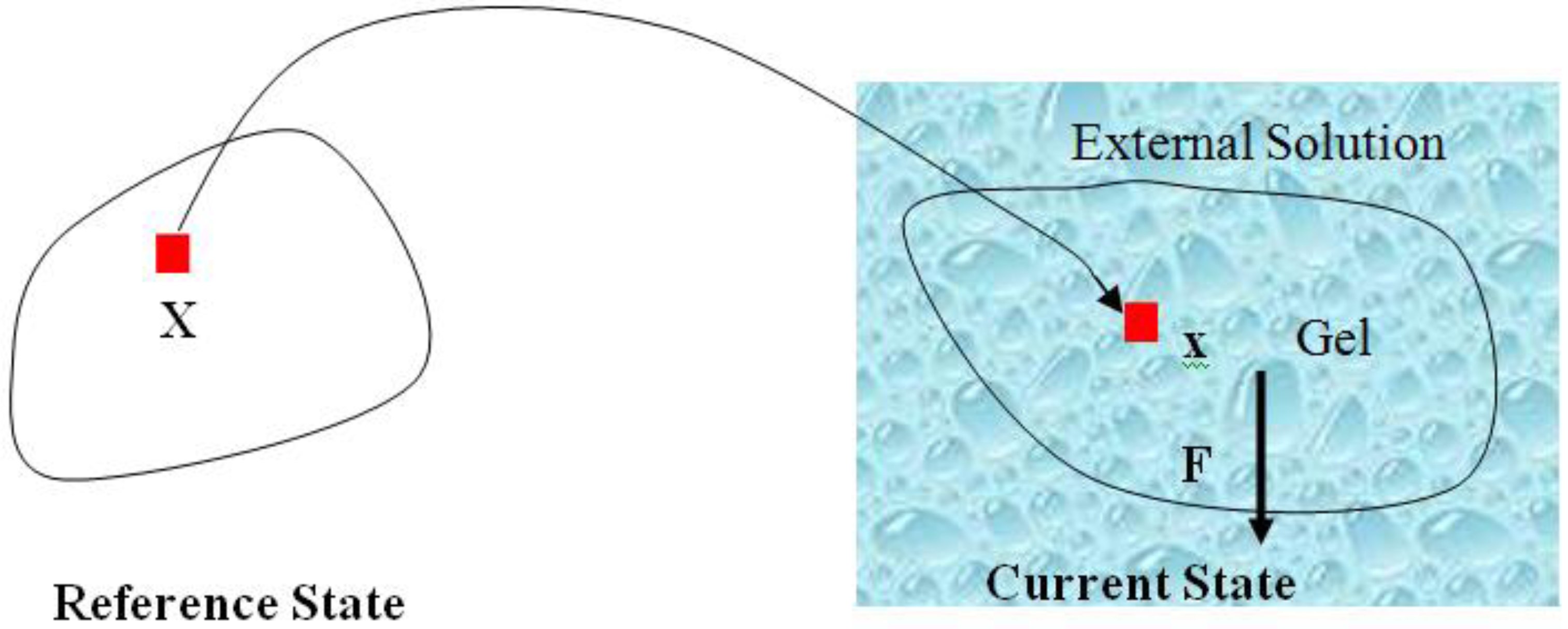
 denotes the number of solvent molecules in an elemental volume
  with a solvent concentration in the gel,
  . The combination of the two fields and describes the state of the gel system in which the field describes the deformation of the network, while describes the distribution of the solvent molecules in the gel system [24,25]. Let
  be the external mechanical body force applied on the elemental volume, and
  the external mechanical force applied on an elemental area. When the network deforms by a small amount,
  , (a small virtual displacement), the field of mechanical load does work
  . The integrals extend over the volume and the surface of the network in the reference state. If we assume
  to be the Helmholtz free energy density, the gel free energy in the elemental volume
  will be
  When the field of concentration in the gel changes by
  the external solution does work
  , where
  is the chemical potential of the solvent molecules. Thermodynamics dictates that the change in the free energy of the gel should equal the sum of the work done by the external mechanical force and the external solvent:
 and . The free energy density of the gel, W, is a function of the deformation gradient of the network, F, and the concentration of the solvent in the gel, C. When the gel equilibrates with the solvent and the mechanical load, the chemical potential, µ, of the solvent molecules is homogeneous in the external solvent and in the gel [24]. Hence the chemical potential will be:

 by using a Legendre transformation:

 is a function of the deformation gradient of the network and the chemical potential of the solvent molecules, that is (F, µ). Combining Equations 2 and 4 gives us:
 (µ) is prescribed, it can be solved via finite element method [24].
 is due to the network stretch, and
  results from the solvent-network blending. The constraint between the deformation field and concentration field can be derived from the assumption of the incompressibility of individual polymeric and water molecules. This constraint is written as
  , where
  is the volume per solvent molecule [24]. The free energies of stretching the network and mixing the solvent with the network are:


 is the number of polymeric chains per reference volumn and
  is a dimensionless measure of the enthalpy of mixing. When
  , the solvent molecules’ diffusion is less energetically favorable. For pH-sensitive gel, the detailed energy form is derived by Marcombe et al. [21]. Following previous work [21,22,23,24], an idealized model is adopted, assuming that the free-energy density of the gel is a sum of several contributions:

 is the energy due to solvent-ion mixing, and
  is derive from the acidic group dissociation.
  and
and  , where
  is the nominal concentration of the hydrogen ions,
  is the nominal concentration of the counter-ion that carries charge of sign opposite to the fixed charge,
  is the nominal concentration of the co-ion that bears a charge of the same sign as the fixed charge. We stipulate that the nominal density of free energy is
  . According to Marcombe et al. [21], the concentrations of the mobile ions are taken to be low, so that their contribution to the free energy is due to the entropy of mixing, namely,

 is a reference value of the concentration of
  species.
 and
and  are the nominal concentrations of the fixed charge and of the associated acidic group. They are constrained by
  , where
  is the ratio between acidic groups on a polymer chain and the total number of monomers on the chain and
  is the volume per monomer. and can be expressed using independent fields as
  (electroneutrality) and
  .
. . Recall that when the number of particles is counted in units of the Avogadro number, NA = 6.023 × 10²³, the molar concentration of the species α is designated by [α]; for example,
 :
:  , for pH-sensitive hydrogel it can be derived as [21]

 as specified above, equation (12) becomes


 is the osmotic pressure due to the imbalance of the number of ions in the gel and in the external solution,
  is the osmotic pressure due to the mixing of the network and the solvent. Using the above governing equations, the free-energy function can be coded into subroutine UHYPER for ABAQUS simulation. More complex boundary value problems can also be solved with the same subroutine.
  , and the following parameters and values are used in the simulation. The number f is the number of acidic groups on a polymer chain divided by the total number of monomers on the chain, f = 0.05;
  is the number of polymer chains per unit volume of the dry network, v is the volume per monomer, 1/Nv is the number of monomers per polymer chain, and Nv = 0.001; χ is a dimensionless measure of the enthalpy of mixing, an indicator of the ease of polymer-solvent interaction, χ = 0.1; dissociation constant pKa = −log10Ka = 4.3, initial stretch
  = 3.39;
  is the concentration in external solution,
  = 6.02 × 10⁻⁵. Besides these basic parameters, the following parameters are involved: kT is the temperature in the unit of energy, kT = 4 × 10⁻²¹ J and kT/v = 4 × 10⁷ Pa at room temperature. A representative value of the volume per molecule is v = 10−28 m3. The elastic modulus of the dry network is NkT. For Nv = 10−3, the elastic modulus is NkT = 4 × 10⁴ Pa. These values are adopted to study the behavior of hydrogel as a microfluidic valve elaborated in section 3.
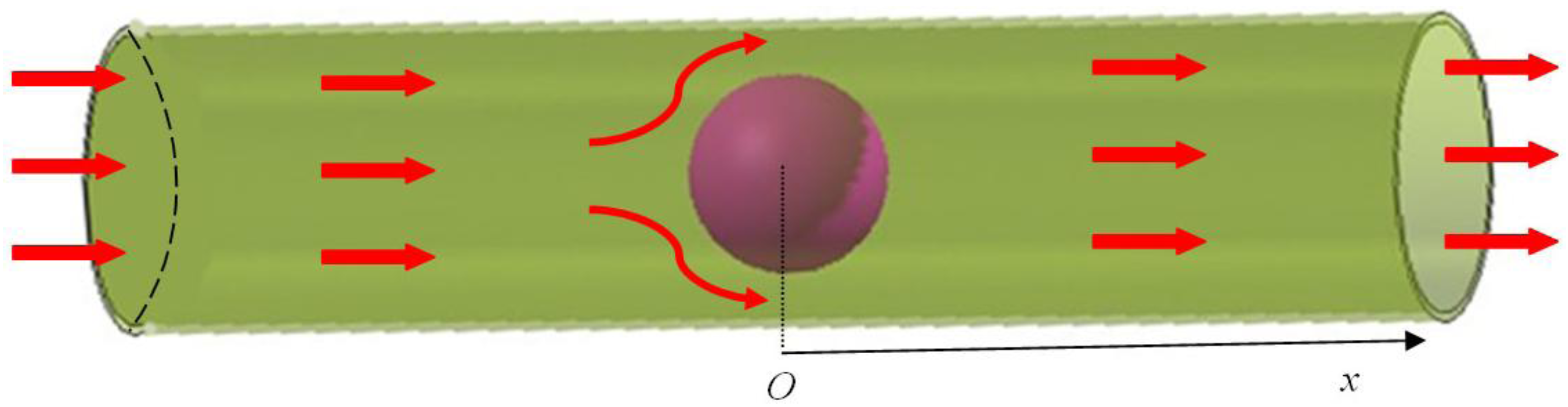
2.2. Fluid-Structure Interaction Models of Hydrogel and Fluid


 ,
,  and
and  denote the fluid velocity, grid velocity and gravitational acceleration respectively. The stress tensor
  is defined as
  , and e denotes the velocity strain tensor, which is in the form of
  . In these formulae, p and
  denote pressure and dynamic viscosity respectively.

 denotes the fluid stresses, and
  and
and  denotes the solid gel displacement and stress respectively at the FSI interface.
 denotes the increment of the displacement. The latest displacement is then updated by adding the incremental solutions.
 3. Results and Discussion
3.1. Free Swelling of pH-sensitive Hydrogel

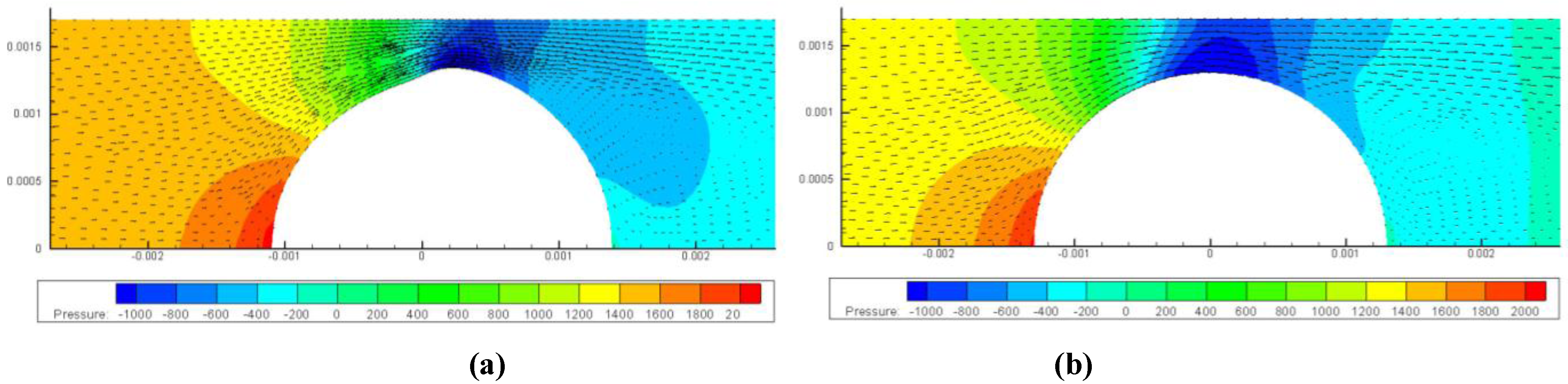
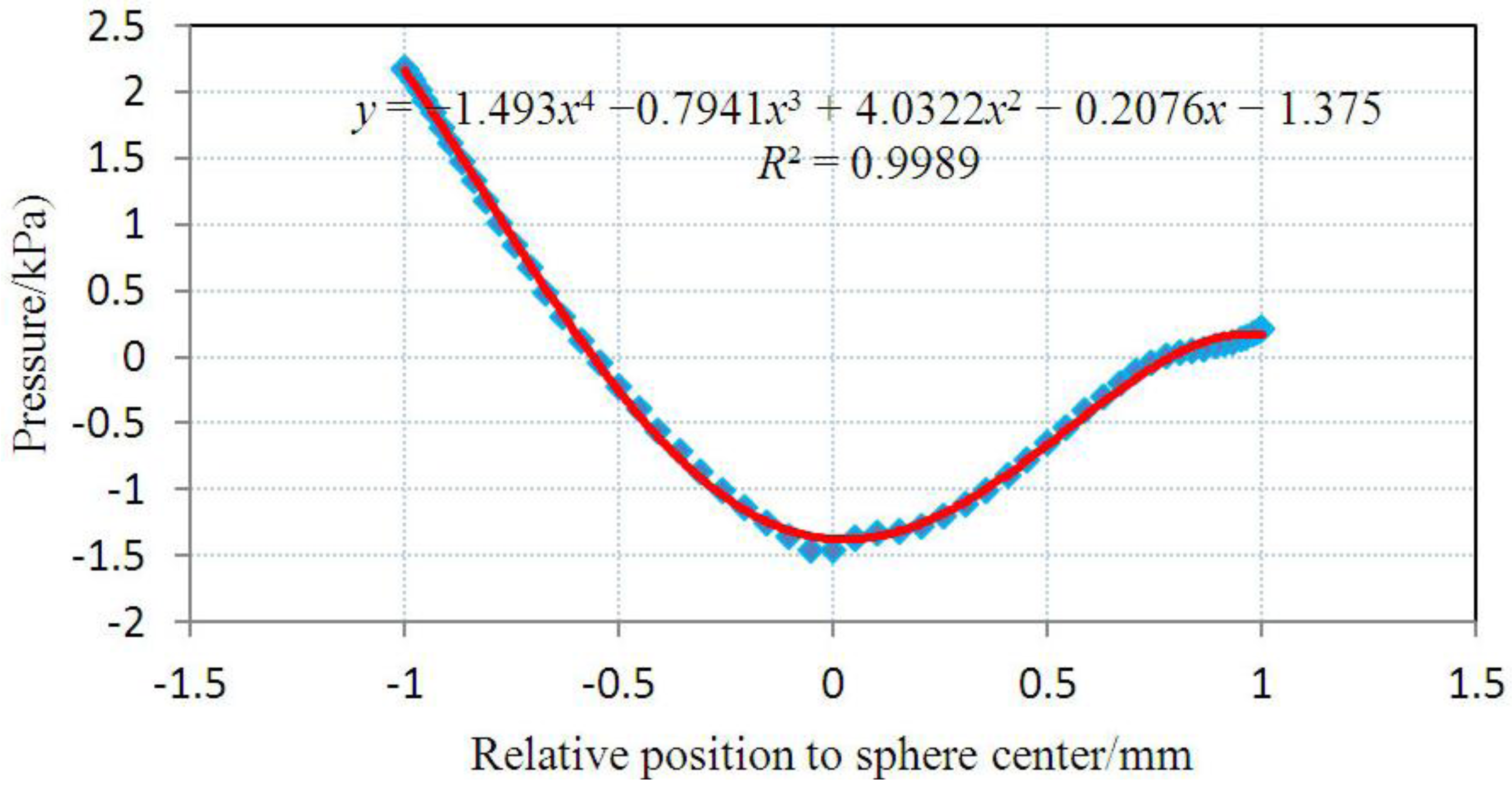
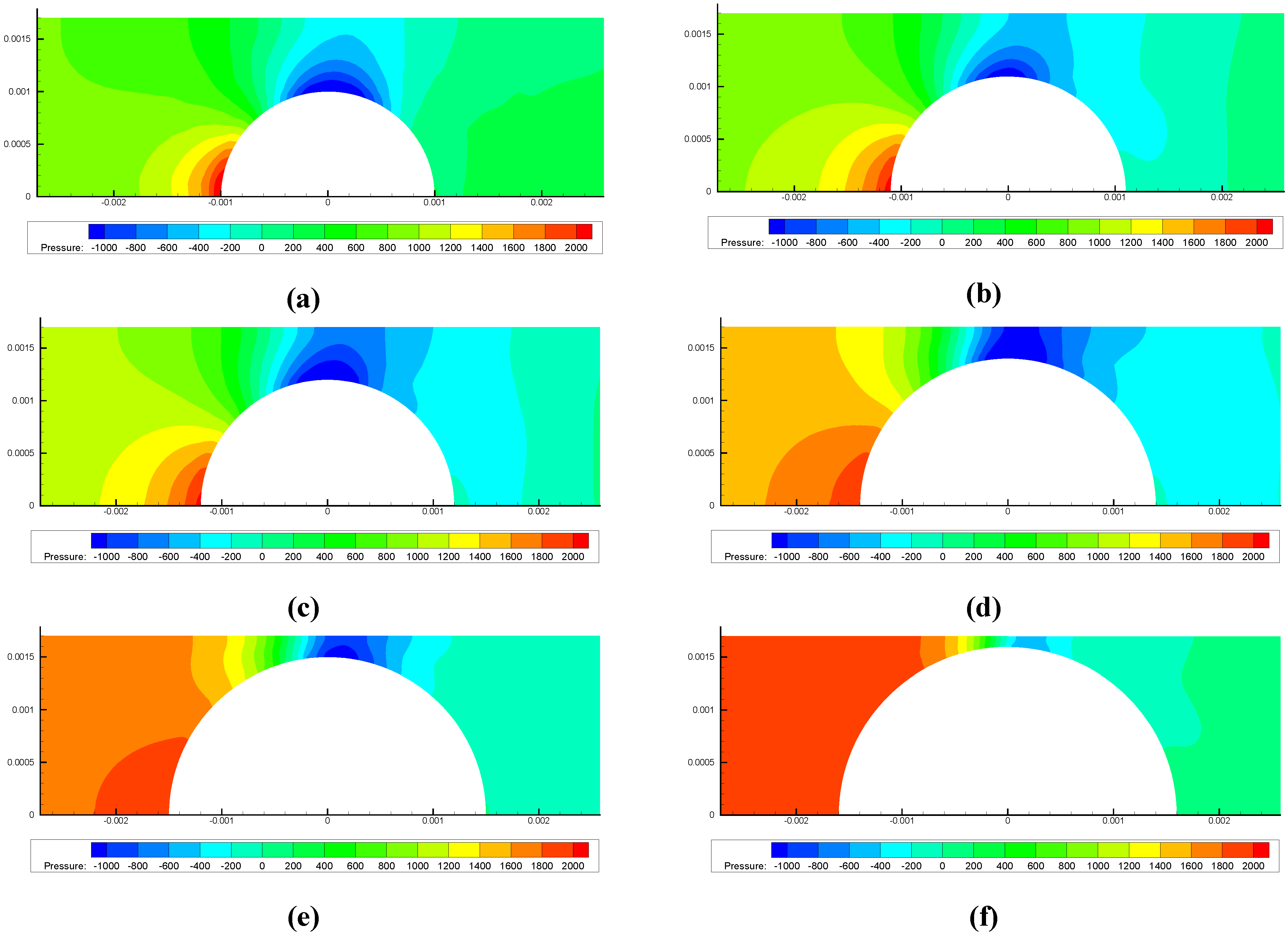
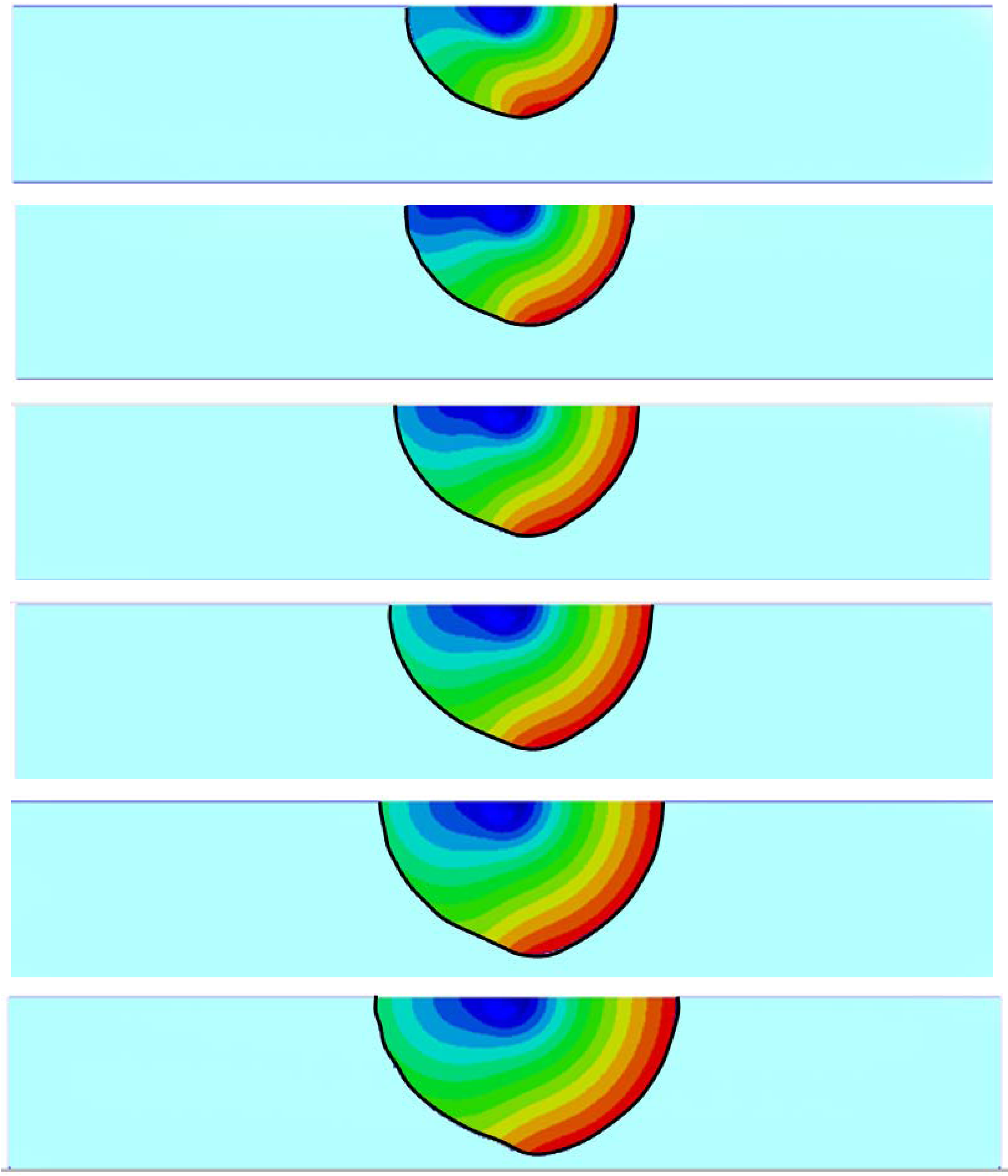
3.2. Inhomogeneous Swelling of Hydrogel as Microfluidic Valve

| Stages | Six stages | Effective radius(mm) | Velocity | FAR | ||
|---|---|---|---|---|---|---|
| Without FSI | With FSI | Without FSI | With FSI | |||
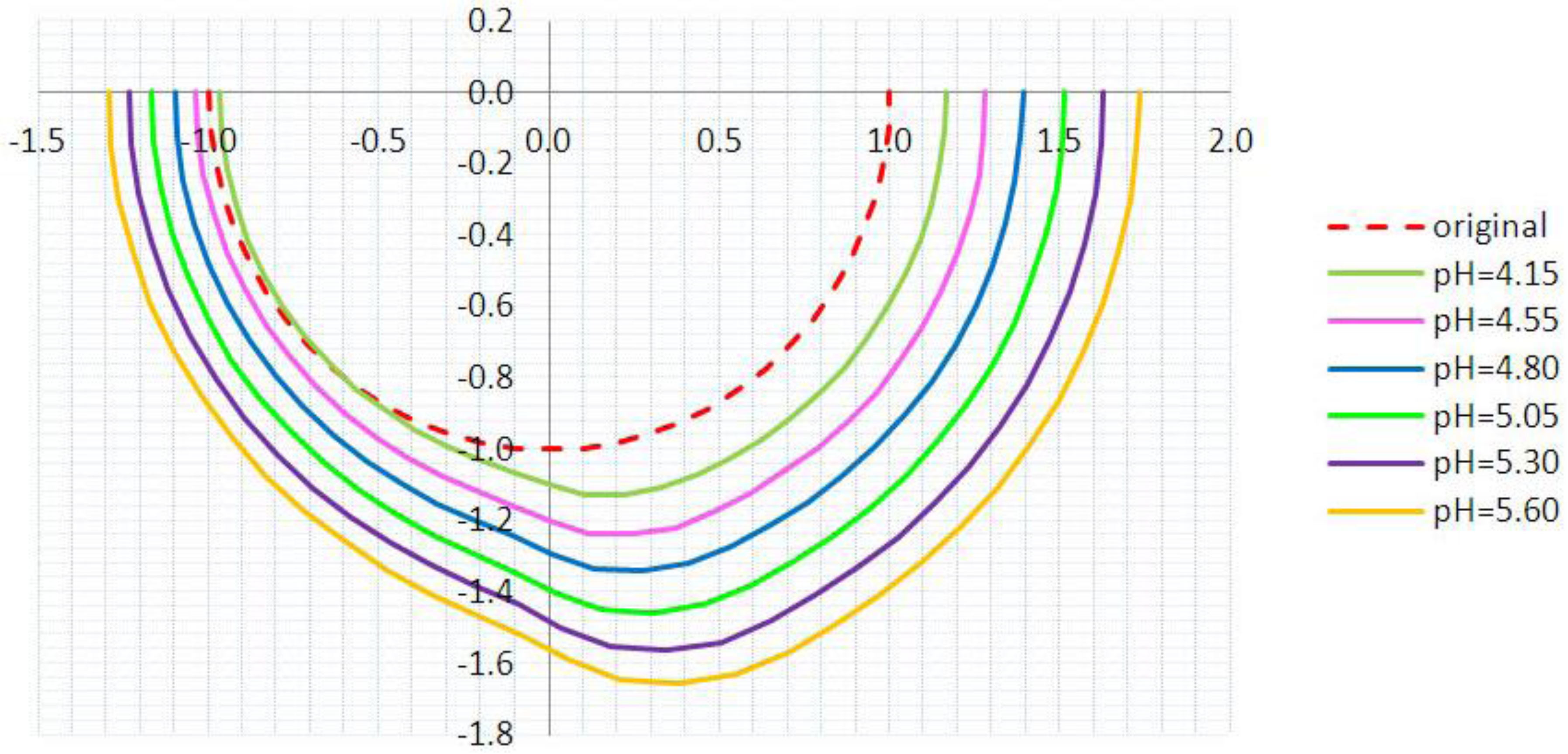
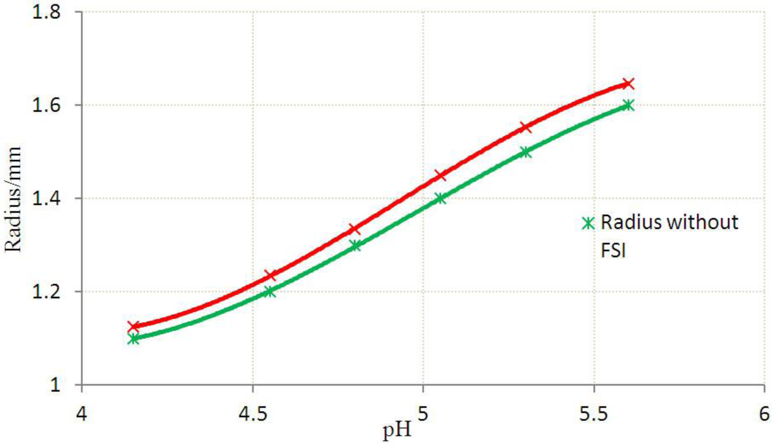
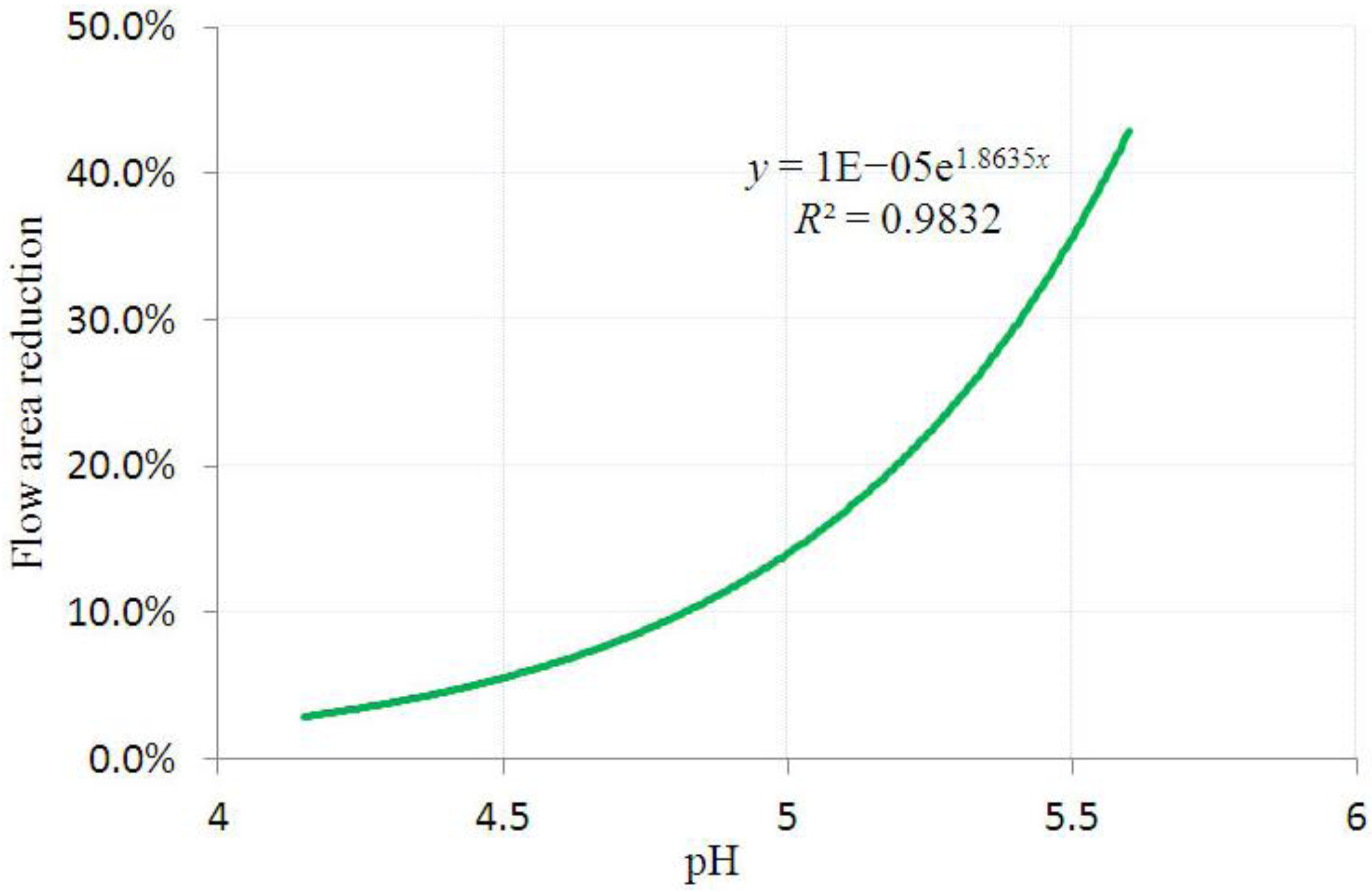
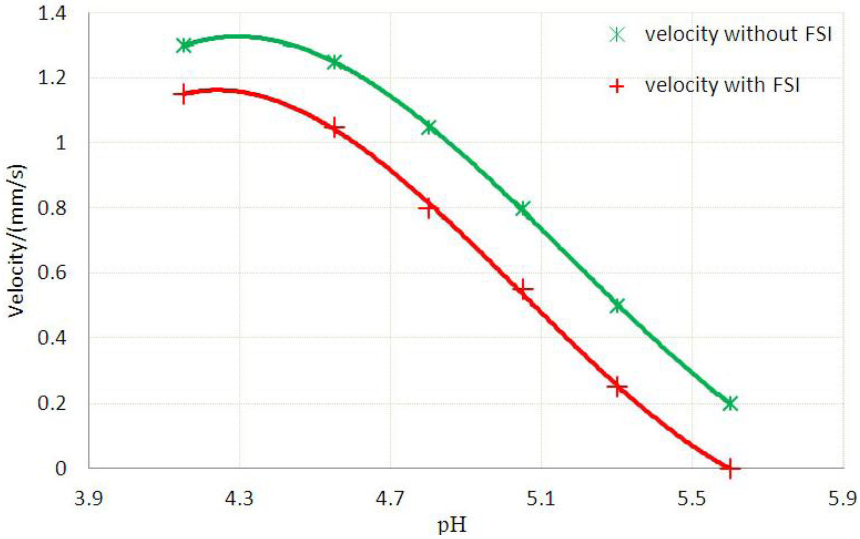
| 1 | pH = 4.15 | 1.100 | 1.125 | 1.30 | 1.15 | 3.3% |
| 2 | pH = 4.55 | 1.200 | 1.235 | 1.25 | 1.05 | 5.9% |
| 3 | pH = 4.80 | 1.300 | 1.335 | 1.05 | 0.80 | 7.7% |
| 4 | pH = 5.05 | 1.400 | 1.450 | 0.80 | 0.55 | 15.3% |
| 5 | pH = 5.30 | 1.500 | 1.554 | 0.50 | 0.25 | 25.8% |
| 6 | pH = 5.60 | 1.600 | 1.647 | 0.20 | 0 | 46.2% |


4. Concluding Remarks
Acknowledgments
References
- Beebe, D.J.; Mensing, G.A.; Walker, G.M. Physics and applications of microfluidics in biology. Annu. Rev. Biomed. Eng. 2002, 4, 261–286. [Google Scholar] [CrossRef]
- Beebe, D.J.; Moore, J.J.S.; Bauer, J.M.; Yu, Q.; Liu, R.H.; Devadoss, C.; Jo, R.-H. Functional hydrogel structures for autonomous flow control inside microfluidic channels. Nature 2000, 404, 588–590. [Google Scholar]
- Hoffmann, J.; Plötner, M.; Kuckling, D.; Fischer, W.J. Photopatterning of thermally sensitive hydrogels useful for microactuators. Sens. Actuat. A 1999, 77(2), 139–144. [Google Scholar]
- Wang, J.; Chen, Z.; Mauk, M.; Mauk, M.; Hong, K.S.; Li, M.; Yang, S.; Bau, H.H. Self-actuated, thermo-responsive hydrogel valves for lab on a chip. Biomed. Microdevices 2005, 7, 313–322. [Google Scholar] [CrossRef]
- Osada, Y.; Rossmurphy, S.B. Intelligent gels. Sci. Amer. 1993, 268, 82–87. [Google Scholar]
- Baldi, A.; Gu, Y.; Loftness, P.E.; Siegel, R.A.; Ziaie, B. A hydrogel-actuated environmentally sensitive microvalve for active flow control. J. Microelectromech. Syst. 2003, 12, 613–621. [Google Scholar] [CrossRef] [Green Version]
- Richter, A.; Paschew, G.; Klatt, S.; Lienig, J.; Arndt, K.-F.; Adler, H.-J.P. Review on hydrogel-based pH sensors and microsensors. Sensors 2008, 8(1), 561–581. [Google Scholar] [CrossRef]
- Seitz, W.R.; Rooney, M.T.V.; Miele, E.W.; Wang, H.; Kaval, N.; Zhang, L.; Doherty, S.; Milde, S.; Lenda, J. Derivatized, swellable polymer microspheres for chemical transduction. Anal. Chim. Acta. 1999, 400, 55–64. [Google Scholar] [CrossRef]
- De, S.K.; Aluru, N.R. A chemo-electro-mechanical mathematical model for simulation of pH sensitive hydrogels. Mech. Mater. 2004, 36, 395–410. [Google Scholar] [CrossRef]
- Hong, W.; Zhao, X.H.; Zhou, J.X.; Suo, Z.G. A theory of coupled diffusion and large deformation in polymeric gels. J. Mech. Phys. Solids 2008, 56, 1779–1793. [Google Scholar] [CrossRef]
- Seigel, R.A. Implantable, Self-Regulating Mechanochemical Insulin Pump. The Regents of the University of California: Berkeley, CA, USA, 1991. [Google Scholar]
- Shahinpoor, M. Microelectromechanics of ionic polymeric gels as electrically controllable artificial muscles. J. Intell. Mater. Syst. Struct. 1995, 6, 307–314. [Google Scholar] [CrossRef]
- Chen, G.P.; Takashi, U.; Tetsuya, T. Scaffold design for tissue engineering. Macromol. Biosci. 2002, 2, 67–77. [Google Scholar] [CrossRef]
- Chan, A.W.; Neufeld, R.J. Modeling the controllable ph-responsive swelling and pore size of networked alginate based biomaterials. Biomaterials 2009, 30, 6119–6129. [Google Scholar] [CrossRef]
- Dong, L.; Jiang, H.R. Autonomous microfluidics with stimuli-responsive hydrogels. Soft matter. 2007, 3, 1223–1230. [Google Scholar] [CrossRef]
- Eddington, D.T.; Beebe, D.J. Flow control with hydrogels. Adv. Drug Rev. 2004, 56, 199–210. [Google Scholar] [CrossRef]
- Yi, C.Q.; Li, C.W.; Ji, S.L.; Yang, M.S. Microfluidics technology for manipulation and analysis of biological cells. Anal. Chim. Acta. 2006, 560, 1–23. [Google Scholar] [CrossRef]
- Johnson, B.; Niedermaier, D.J.; Crone, W.C.; Moorthy, J.; Beebe, D.J. Mechanical properties of a pH sensitive hydrogel. In Proceedings of the 2002 Society for Experimental Mechanics (SEM) Annual Conference, Milwaukee, WI, USA, 10–12 June 2002; pp. 1–2.
- Zhao, B.; Moore, J.S. Fast pH and ionic strength-responsive hydrogels in microchannels. Langmuir 2001, 17, 4758–4763. [Google Scholar] [CrossRef]
- Kurnia, J.C.; Erik-Birgersson, E; Mujumdar, A.S. Computational study of pH-sensitive hydrogel-based microfluidic flow controllers. J. Funct. Biomater. 2011, 2, 195–212. [Google Scholar] [CrossRef]
- Marcombe, R.; Cai, S.; Hong, W.; Zhao, X.; Lapusta, Y.; Suo, Z. A theory of constrained swelling of a pH-sensitive hydrogel. Soft Matter. 2010, 6, 784–793. [Google Scholar]
- De, S.K.; Aluru, N.R.; Jhonson, B; Crone, W.C.; Beebe, D.J.; Moore, J. Equilibrium swelling and kinetics of pH-responsive hydrogels: Models, experiments and simulations. J. Microelectromech. Syst. 2002, 11, 544–555. [Google Scholar] [CrossRef]
- Hu, Y.H.; You, J.O.; Auguste, D.T.; Suo, Z.; Vlassak, J.J. Indentation: A simple, nondestructive method for characterizing the mechanical and transport propertie of pH-sensitive hydrogels. J. Mater. Res. 2012, 27, 152–160. [Google Scholar] [CrossRef]
- Hong, W.; Liu, Z.S.; Suo, Z.G. Inhomogeneous swelling of a gel in equilibrium with a solvent mechanical load. Int. J. Solids Struct. 2009, 46, 3282–3289. [Google Scholar] [CrossRef]
- Liu, Z.S.; Hong, W.; Suo, Z.G.; Swaddiwudhipong, S.; Zhang, Y.W. Modeling and simulation of buckling of polymeric membrane thin film gel. Comput. Mater. Sci. 2010, 49, S60–S64. [Google Scholar] [CrossRef]
- Liu, Z.S.; Swaddiwudhipong, S.; Cui, F.S.; Hong, W.; Zhang, Y.W. Analytical solutions of polymer gel structures under buckling and wrinkle. Int. J. Appl. Mech. 2011, 3, 235–257. [Google Scholar] [CrossRef]
- Flory, P.J.; Rehner, J. Statistical mechanics of cross-linked polymer networks I. Rubber elasticity. J. Chem. Phys. 1943, 11, 512–520. [Google Scholar] [CrossRef]
- Flory, P.J.; Rehner, J. Statistical mechanics of cross-linked polymer networks II. Swelling. J. Chem. Phys. 1943, 11, 521–526. [Google Scholar] [CrossRef]
- Ricka, J.; Tanaka, T. Swelling of ionic gels: Quantitative performance of the Donnan Theory. Macromolecules 1984, 17, 2916–2921. [Google Scholar] [CrossRef]
- Brannon-Peppas, L.; Peppas, N.A. Equilibrium swelling behavior of dilute ionic hydrogels in electrolytic solutions. Chem. Eng. Sci. 1991, 46, 715–722. [Google Scholar] [CrossRef]
© 2012 by the authors; licensee MDPI, Basel, Switzerland. This article is an open access article distributed under the terms and conditions of the Creative Commons Attribution license (http://creativecommons.org/licenses/by/3.0/).
Share and Cite
Zhang, Y.; Liu, Z.; Swaddiwudhipong, S.; Miao, H.; Ding, Z.; Yang, Z. pH-Sensitive Hydrogel for Micro-Fluidic Valve. J. Funct. Biomater. 2012, 3, 464-479. https://doi.org/10.3390/jfb3030464
Zhang Y, Liu Z, Swaddiwudhipong S, Miao H, Ding Z, Yang Z. pH-Sensitive Hydrogel for Micro-Fluidic Valve. Journal of Functional Biomaterials. 2012; 3(3):464-479. https://doi.org/10.3390/jfb3030464
Chicago/Turabian StyleZhang, Yan, Zishun Liu, Somsak Swaddiwudhipong, Haiyan Miao, Zhiwei Ding, and Zhengzhi Yang. 2012. "pH-Sensitive Hydrogel for Micro-Fluidic Valve" Journal of Functional Biomaterials 3, no. 3: 464-479. https://doi.org/10.3390/jfb3030464