Reducing JPEG False Contour Using Visual Illumination


1
Department of Informatics, Universitas Sebelas Maret (UNS), Surakarta 57126, Indonesia
2
Department of Informatics, Universitas Maritim Raja Ali Haji (UMRAH), Kepulauan Riau 29115, Indonesia
*
Author to whom correspondence should be addressed.
Information 2018, 9(2), 41; https://doi.org/10.3390/info9020041
Submission received: 28 December 2017
/
Revised: 12 February 2018
/
Accepted: 13 February 2018
/
Published: 20 February 2018
Abstract
:This paper presents an efficient and simple technique on reducing the false contour problem which often occurs in the JPEG decoded image. The false contour appears on JPEG decoded image while applying small quality factor. This problem induces unpleasant visual appearance. The proposed scheme exploits the usability of Halftoning-Based Block Truncation Coding (HBTC) approach on generating visual illumination to reduce the aforementioned problem. Three HBTC techniques, namely Ordered Dither Block Truncation Coding (ODBTC), Error Diffusion Block Truncation Coding (EDBTC) and Dot Diffused Block Truncation Coding (DDBTC), modify the DC components of all Discrete Cosine Transform (DCT) processed image on JPEG encoding stage. Experimental results show the proposed method superiority on JPEG false contour reduction. To further improve the JPEG decoded image quality, the proposed method utilizes the Gaussian kernel on replacing the DDBTC diffused kernel on spreading the error term. It assumes that the adjacent image blocks have a strong correlation in which high diffused coefficient should be applied on nearest adjacent neighbor. This paper extends the HBTC usability on JPEG false contour suppression.
1. Introduction
Reducing the required storage space for recording digital image in computer has attracted many attentions for image processing researchers. Some research efforts have been devoted for image compression fields to develop a new compression technique and to further reduce the required storage of compressed image. Several image compression techniques have been proposed and documented in literatures such as JPEG scheme and HBTC method [1,2,3]. Among of them, the JPEG scheme yields a promising result on decoded image quality as well as required storage bits. The JPEG gives a good result on decoded image while applying a high JPEG quality factor. However, the false contour problem occurs on a JPEG decoded image when applying the low-quality factor. This problem induces unpleasant visual effect.
The JPEG false contour can be easily reduced by modifying the DC components of DCT-transformed image. This modification is only performed on the encoding stage, whereas the decoding module simply performs the original JPEG inverse process without additional operation related to DC values. A simple approach has been proposed in [4] for modifying the DC components. This method de-correlates the adjacency criterion and neighbor correlation in DC components using EDBTC approach. It performs the thresholding operation and diffuses error term of processed DC components into its neighbor to generate illumination effect. Using this simple method, the quality of JPEG decoded image can be improved. At the same time, it reduces the appearance of false contour in the decoded image. As reported in the literature, this method achieves better performance compared to that of the former existing scheme.
To further reduce the false contour problem occurring in JPEG decompression stage, some simple techniques are proposed in this paper. These techniques exploit the HBTC effectiveness for generating the visual illumination. Herein, the DC components are modified using the HBTC on the JPEG encoding process. Using this strategy, the visual illumination helps the JPEG on suppressing false contour in the decoding stage. The HBTC methods have been proven to give a promising result for image compression as reported in [1,2,3]. Due to its simplicity, several applications have been developed under the HBTC framework such as image watermarking [5], image retrieval [4,6,7,8,9], inverse half toning method [10,11,12], data hiding [13] and image security [14]. As reported in the experimental result section, the proposed method effectively reduces the JPEG false contour artifacts.
At the end, this paper is organized as follow: Section 2 delivers the related works on JPEG image compression and the former scheme on reducing the JPEG false contour. Section 3 presents the proposed method on reducing the JPEG false contour using two HBTC techniques. The first technique employs the ODBTC approach on generating the visual illumination, whereas the second technique utilizes the DDBTC to obtain better result on JPEG false contour reduction. An improvement version of the proposed DDBTC scheme is also presented in this section by modifying the Gaussian filtering to further generate better visual illumination. Some extensive experiments are reported in Section 3 along with the discussion on the finding results. Finally, the conclusion is drawn in Section 4.
2. Related Works
This section presents a brief introduction of JPEG image compression under a specific quality factor. It gives an example of JPEG false contour problem which often appear on JPEG decoded image with low value of quality factor. The former method on reducing JPEG false contour is also presented in this section.
2.1. JPEG Image Compression
The JPEG image compression scheme is firstly introduced in this section. The JPEG reduces the required bit for storing a given image by utilizing the usability of quantization process. The quantization process enforces most of the image pixels into lower entropy. The JPEG utilizes the quantization matrix determined by quality factor. Quantization matrix determines the decompressed image quality. In the JPEG compression, the quantization factor lies in the interval [0, 100] in which the zero value denotes the poorest decompressed image quality, whereas the 100 value indicates the best decompressed image quality. The false contour often occurs at the JPEG decompressed image by choosing a small quality factor such as 5, 8, 10, etc.
In JPEG image compression, an input image (subtracted with 128) is firstly transformed using the Discrete Cosine Transformation (DCT). The quantization process is subsequently performed in this transformed image before lossless entropy coding. Let be an image of size . In the JPEG encoding stage, this image is divided into several non-overlapping image blocks of size . A set of image blocks are then denoted as , where . The symbol denotes the image block position in row and column. Each image block is firstly subtracted with the mean pixel distribution, i.e. 128, as indicated with . This substracted image block is further transformed using DCT as follow:
where and denote the transformed image block and DCT operator, respectively. The DCT operator produces the DC and AC components of an image. The DCT transformed coefficient of each image block is then defined as:
where and are the DC and AC components, respectively, of DCT transformed image block at position . By setting the quality factor , the quantization process enforces the DCT transformed coefficients into zero values as much as possible. The quantization process is formally defined as:
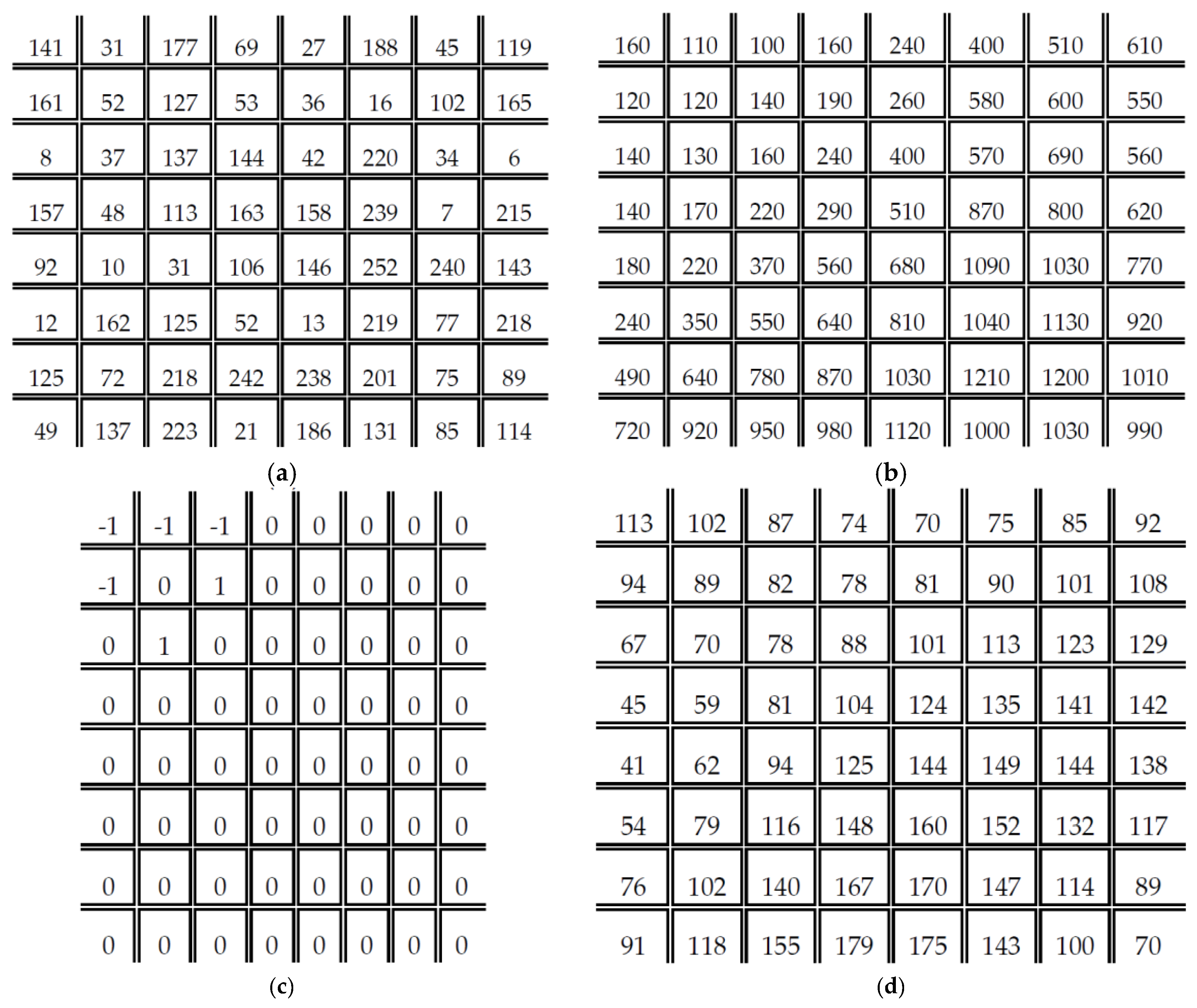
where represents the quantization matrix of the same size with the image block size. The symbol denotes the truncation operator to force the quantized DCT coefficient into the nearest integer. The image block is subsequently encoded using the entropy coding. The DC and AC coefficients are processed using the Differential Pulse Code Modulation (DPCM) and lossless Huffman coding, respectively. Figure 1 illustrates an example of JPEG image compression by choosing the quality factor . As shown in Figure 1c, the zero values dominate the encoded image block . This phenomenon is caused by the quantization process as formulated in Equation (3). By applying the JPEG decoding process, one may obtain the decoded image block as shown in Figure 1d. The pixel values in an input image are almost different with the pixel values of decoded image. This phenomenon induces the false contour problem in the JPEG decoding stage when utilizing a small quality factor.
To alleviate the JPEG false contour appearance, the proposed method utilizes the visual illumination by exploiting the Halftoning-based Block Truncation Coding (HBTC) approaches, i.e. ODBTC and DDBTC scheme. These schemes are applied on the DC coefficient of DCT transformed image block. Herein, all DC components over all image blocks are firstly collected into a single matrix as follow:
for . The HBTC performs the dithering and diffused operation in the matrix to gives the visual illumination. Specifically, the HBCT operation on is conducted as follow:
where and denote the modified DC components and HBTC operator, respectively. The modified DC coefficient replaces the original DC component as:
The last step is quantized this modified image block before performing the entropy coding as follow:
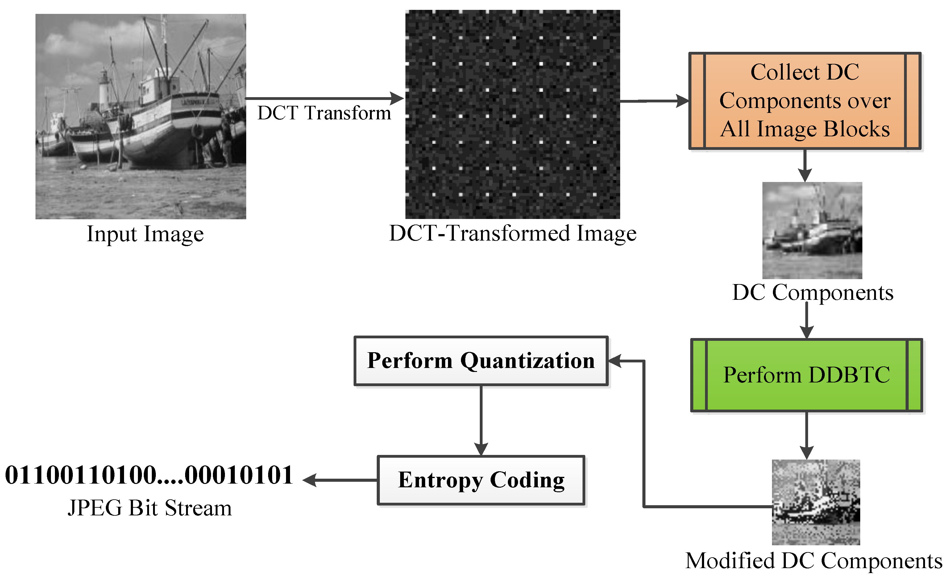
Figure 2 shows the schematic diagram of JPEG false contour reduction using HBTC operation, namely DDBTC approach. This simple strategy effectively suppresses the false contour problem which often occurs in the JPEG image compression. It is noteworthy that the proposed method is only applied on JPEG encoding scheme, while the additional post processing is not required at the decoding side. Thus, we can use the standard JPEG decoding process for the proposed scheme.
2.2. Error Diffused Method
The error diffusion approach has been proposed in Reference [15] to modify the DC components and introduce the visual illumination on the JPEG decoded image. Herein, the HBTC performs the modification on DC components using the EDBTC approach. The EDBTC approach on JPEG false contour reduction can be formally defined as:
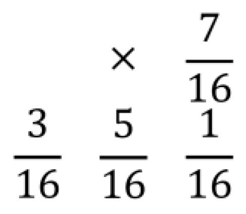
The EDBTC operation produces the visual illumination by exploiting the usability of the error kernel. In this research, we simply use the Floyd-Steinberg error kernel for performing the EDBTC thresholding stage. Figure 3 depicts Floyd-Steinberg error kernel utilized in this research. The symbol in this error kernel denotes the current processed pixel, i.e. the center of error kernel.
In the EDBTC approach, an input image/matrix is firstly decomposed into several non-overlapping image blocks of size . Let be an image block size. The EDBTC requires the threshold value for performing the thresholding process. Herein, the mean value of each image block is regarded as threshold value which can be easily computed as:
By utilizing this threshold value, the EDBTC modifies the DC components by using the following thresholding strategy:
The EDBTC replaces the original DC components with the minimum or maximum value found on the image block using the simple thresholding method. Beside of thresholding operation, the EDBTC needs to diffuse the error caused by this thresholding process. It can be regarded as the most important step in EDBTC approach. The error of a given pixel/element can be calculated as:
This error calculation simply measures the degree of difference between the actual pixel/element value with the replaced value (minimum or maximum value). The error should be diffused or spread out into its neighbor to create the illumination effect. The error diffusion around its surrounding neighbors can be easily computed as follow:
where and represent the error term caused by thresholding operation and the error kernel, respectively. The symbol denotes the convolution operation. At the end, all DC components are replaced with the modified DC coefficients . Using this approach, the JPEG false contour can be reduced such that the JPEG decoded image becomes more satisfied for human vision.
3. Proposed Method for Reducing JPEG False Contour
This section presents the proposed method on reducing the JPEG false contour. The proposed method exploits the effectiveness and usability of ODBTC and DDBTC schemes to reduce the aforementioned problem. The ODBTC and DDBTC methods produce the visual illumination which is very useful to suppress the false contour artifacts. To further improve the performance, a slight modification is proposed on DDBTC method by employing the Gaussian kernel in the DDBTC process. This simple modification offers a better result, at the same time, it simply requires low computational burden.
3.1. Ordered Dither Method
The simple approach on reducing the JPEG false contour is with the dithering method. The DC components of all image blocks, i.e. the matrix is fed into the HBTC module to yield the modified DC coefficients. In the dithering approach, the ODBTC performs the DC coefficients modification as follow:
The ODBTC has been proved to yield a good illumination effect by exploiting the dither array. The ODBTC performs the dithering operation on block-wise of an input image/matrix.
In the ODBTC processing, the matrix is firstly divided into several non-overlapping image blocks of size . Let be an image block. The minimum and maximum values of this image block are required in the ODBTC process which can be computed as follow:
where and denote the minimum and maximum values of each image block, respectively. The symbol represent the pixel/matrix position.
The ODBTC employs the dither array of the same size image block, i.e. , to generate the illumination effect. This dither array can be offline pre-trained over several training images. However, the determination of dither array coefficients is out of paper scope. Figure 4a shows an example of dither array . The scaled dither array can be easily computed as follow:
where is the scaled value which can be calculated as Figure 4b–f gives some examples of scaled dither array over various . These scaled dither array can be stored in the Look-Up-Table (LUT) for later usage in order to speed up the computational time. The ODBTC subsequently modifies the DC components using the simple thresholding approach as follow:
for all . Using this scenario, the modified DC components can be obtained. The ODBTC perform the dithering operation over all image blocks. All image blocks are then combined into a single matrix using the following operation:
The matrix is used to replace and modify the original DC coefficients as indicated in (6). The ODBTC can effectively reduce the JPEG false contour by introducing the dithering-based visual illumination.
3.2. Dot Diffused Method
The more sophisticated approach for creating the visual illumination on JPEG false contour reduction is by utilizing the dot diffused method. Herein, the false contour is reduced using the HBTC approach, i.e. DDBTC. The DDBTC is almost similar to EDBTC in which the error value caused by thresholding approach are delivered into its surrounding neighbors. However, the processing order between these two aforementioned methods is totally different. The DDBTC requires the fix processing order to generate dot-like visual illumination. Specifically, the DDBTC process on JPEG false contour reduction can be defined as follow:
Figure 2 depicts the schematic diagram of the DDBTC method for reducing the JPEG false contour. In contrast to EDBTC, the DDBTC needs the class matrix for indicating the processing order as shown in Figure 5. Herein, different image block requires different class matrix. In addition, the DDBTC also employs the diffused kernel as given in Figure 6 in which different image block uses different diffused kernel.
Let be an image block of size as defined in the previous subsection. The pixel/element of is processed based on the processing order given in the class matrix . Suppose be a processing order. The is the processed pixel/element, i.e. one pixel is processed after completing the other pixel. The DDBTC method performs the thresholding operation on generating the visual illumination by incorporating the mean value as threshold value. The DDBTC thresholding approach can be performed as follow:
where and are the minimum and maximum value computed on an image block, respectively. This thresholding process is only workable on non-concurrent condition, i.e. one pixel processing must be finished before going to another pixel. Similar to EDBTC, the DDBTC thresholding approach induces the error term which is the different between the original pixel/element value with the threshold value. The error computation for each pixel/element can be defined as:
To generate better illumination result, this error term is diffused into its surrounding neighbors using the following strategy:
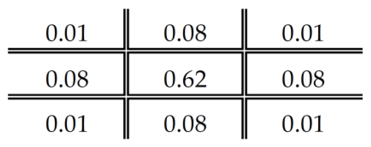
where denotes the diffused kernel. Since the adjacent pixel values have higher degree of correlation, the simple diffused kernel is not enough to spread the error after DC components thresholding. The Gaussian diffused kernel offers better kernel coefficient for diffusing the error term. The Gaussian diffused kernel can be easily computed as:
where denotes the standard deviation of Gaussian diffused kernel. Figure 7 shows an example of Gaussian diffused kernel for generating visual illumination. Using this kernel, the JPEG false contour can be easily reduced to yield more pleasant JPEG decoded image. The DDBTC Gaussian approach utilizes the class matrix which is similar to that of the classical DDBTC method as shown in Figure 5, whereas the main different between these two approaches are simply on diffused kernel.
The key aspects of the proposed method in the JPEG false contour reduction are summarized in Table 1. Different HBTC methods utilize different strategies for modifying the DC-components. The HBTC techniques are only applied on encoder side, however, the standard JPEG decoding module can be directly used to obtain the decoded image. This decoded image is with the JPEG false contour reduction result.
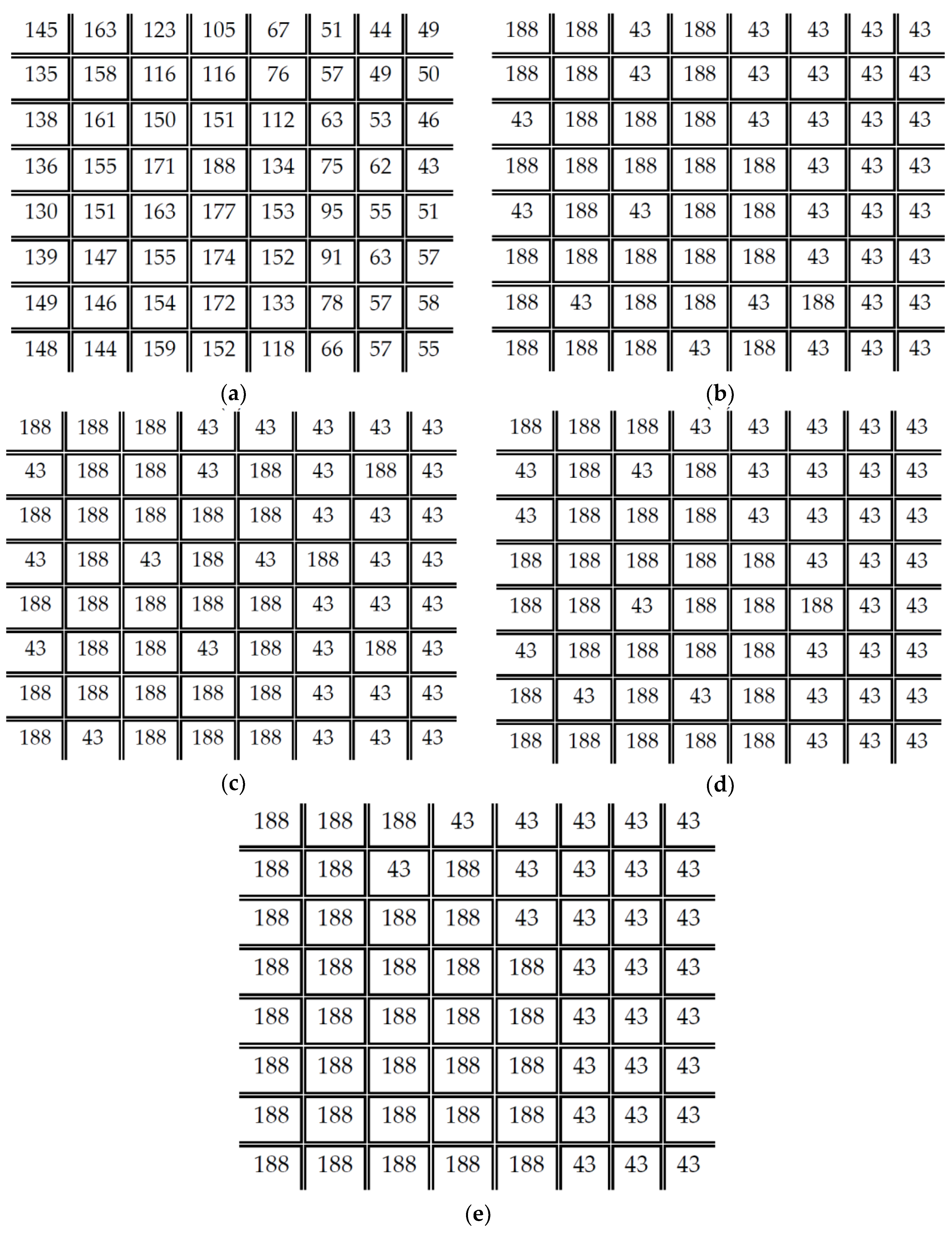
Figure 8 gives some numerical examples of HBTC processes. Herein, Figure 8a shows input image in grayscale. Figure 8b is the processed image using EDBTC method, while Figure 8c is the result of after appying ODBTC. Figure 8d–e show the image with DDBTC and DDBTC Gaussian respectively. As it can be seen from these figures, different HBTC methods produce different visual illumination of .
4. Experimental Results
Some extensive experiments were conducted to examine the proposed method performance. Several images are turned as testing data to investigate the usability of the proposed method for reducing JPEG false contour. This section firstly presents the experimental condition. The subsequent discussion reports some experimental results of the proposed method under visual investigation. The next subsection discusses the block size effect on the overall performances of the proposed method. At last, the superiority of the proposed method is compared to the former existing scheme in the JPEG false contour reduction application.
4.1. Experimental Setup
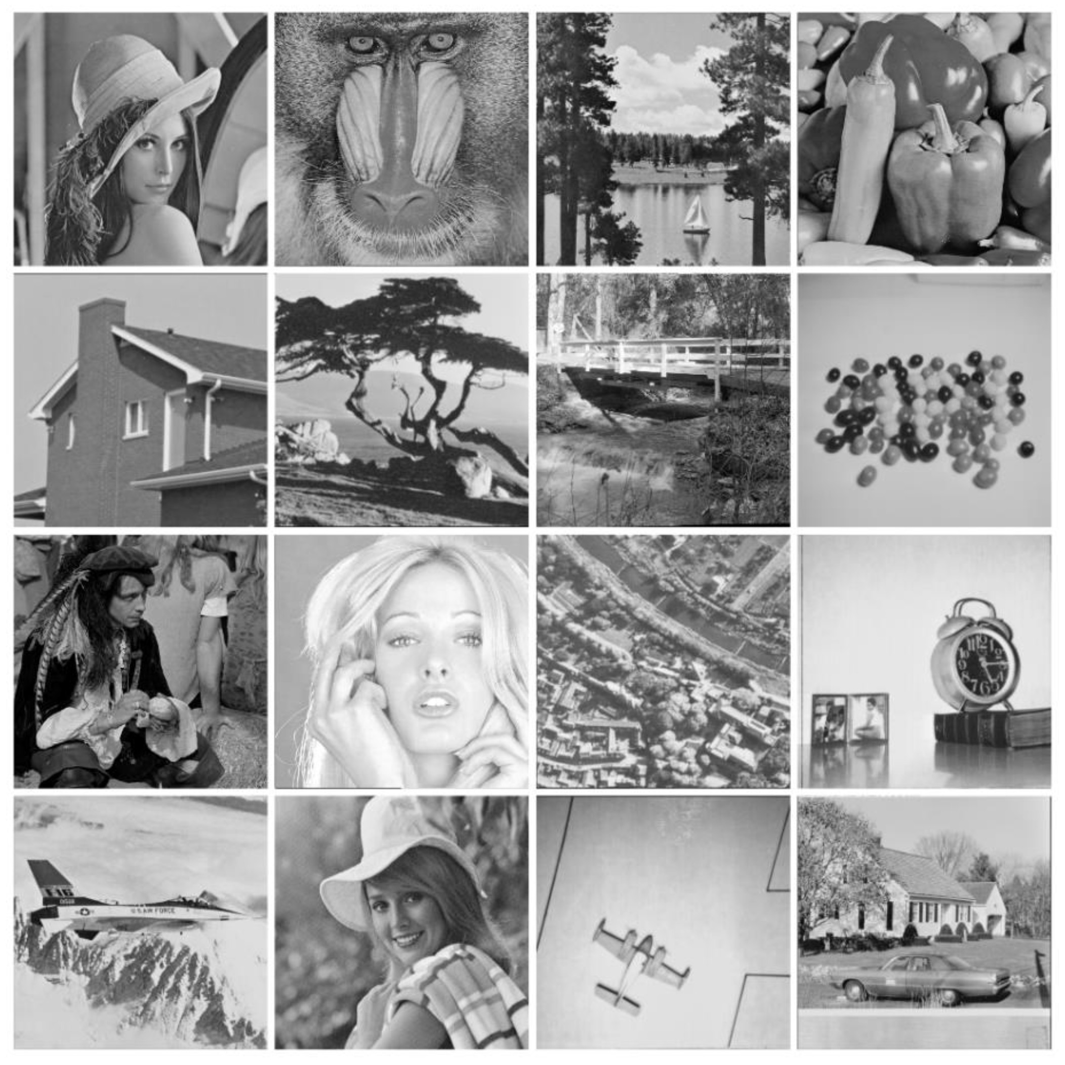
In this research, the performance of the proposed method is evaluated under two image datasets, namely Image Set 1 and Image Set 2. These two image datasets consist of 16 grayscale images under various image content, complexity, brightness, flatness, different conditions, etc. Each image is of size . Figure 9 and Figure 10 show all images on Image Set 1 and Image Set 2, respectively. In spite of using the images of size , the performance of the proposed method is also investigated under higher image sizes such as . Herein, a set of images with higher size are the upsampled version of a given image set. This paper utilizes bicubic interpolation to obtain the upsampled image of size , where denotes the upsampled factor.
The proposed method performance is evaluated under subjectively visual investigation and objectively image quality assessment. In subjective image quality assessment, the correctness and usability of the proposed method are simply examined using human visual observation. While the proposed method produces a pleasant JPEG decoded image, it is said the proposed method yield a good performance on reducing the JPEG false contour. On the other hand, the proposed method performance is further measured with objectively image quality assessment metric, namely Peak-Signal-to-Noise Ratio (PSNR) as previously used in [15]. Higher PSNR value indicate better image quality.
4.2. Visual Investigation of the Proposed Method
This subsection presents the proposed method performance under human visual investigation. In this experiment, the effectiveness and usability of the proposed method for reducing the false contour are investigated on the visual quality of JPEG decoded image. Firstly, an input image is transformed using DCT to obtain the DC and AC components. The DC components over all image blocks are subsequently modified using the ODBTC, EDBTC and DDBTC techniques to examine the proposed method performance. Two images from Image Set 1 and Image Set 2 are chosen in this experiment. Herein, the JPEG image compression encodes these two images using the small quality factor, i.e. . This quality factor induces the false contour on decoded images.
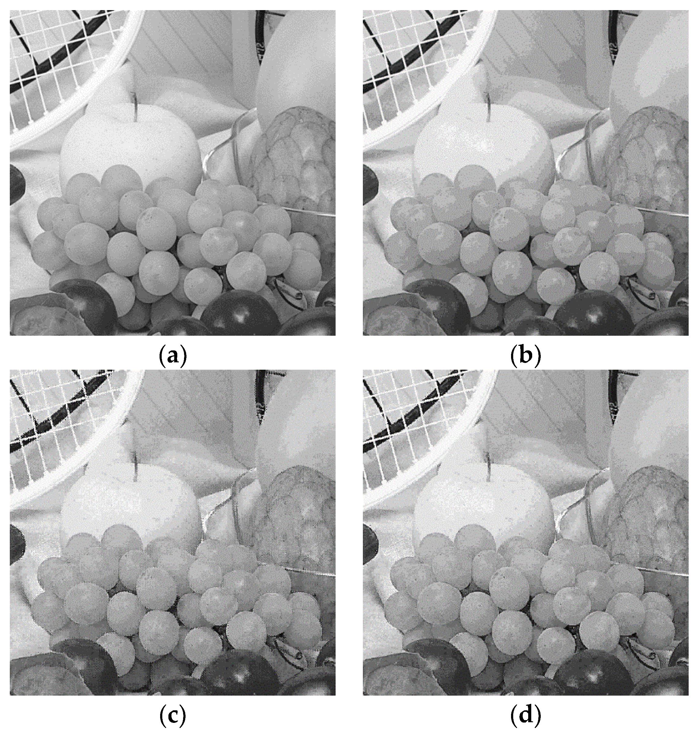
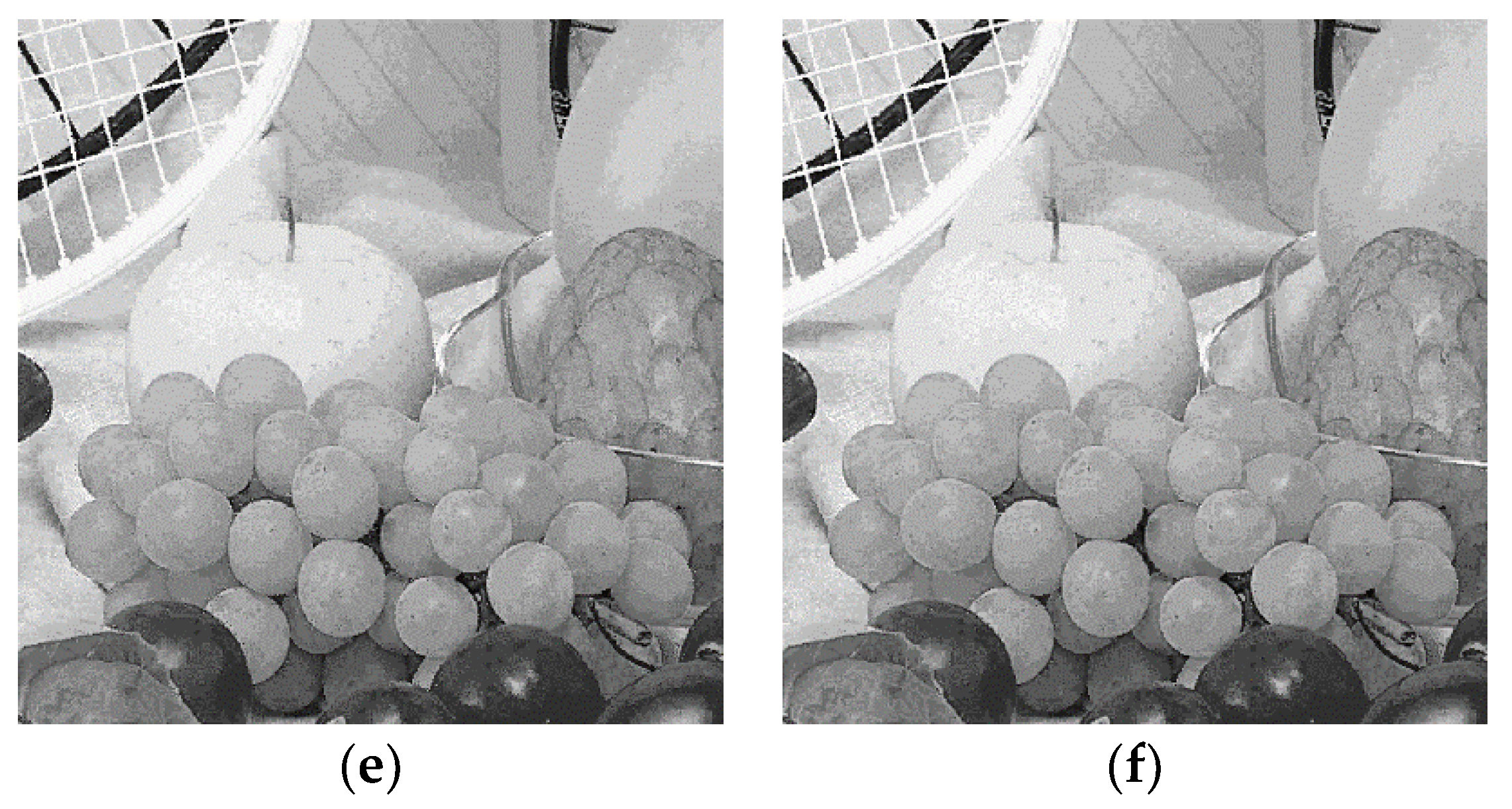
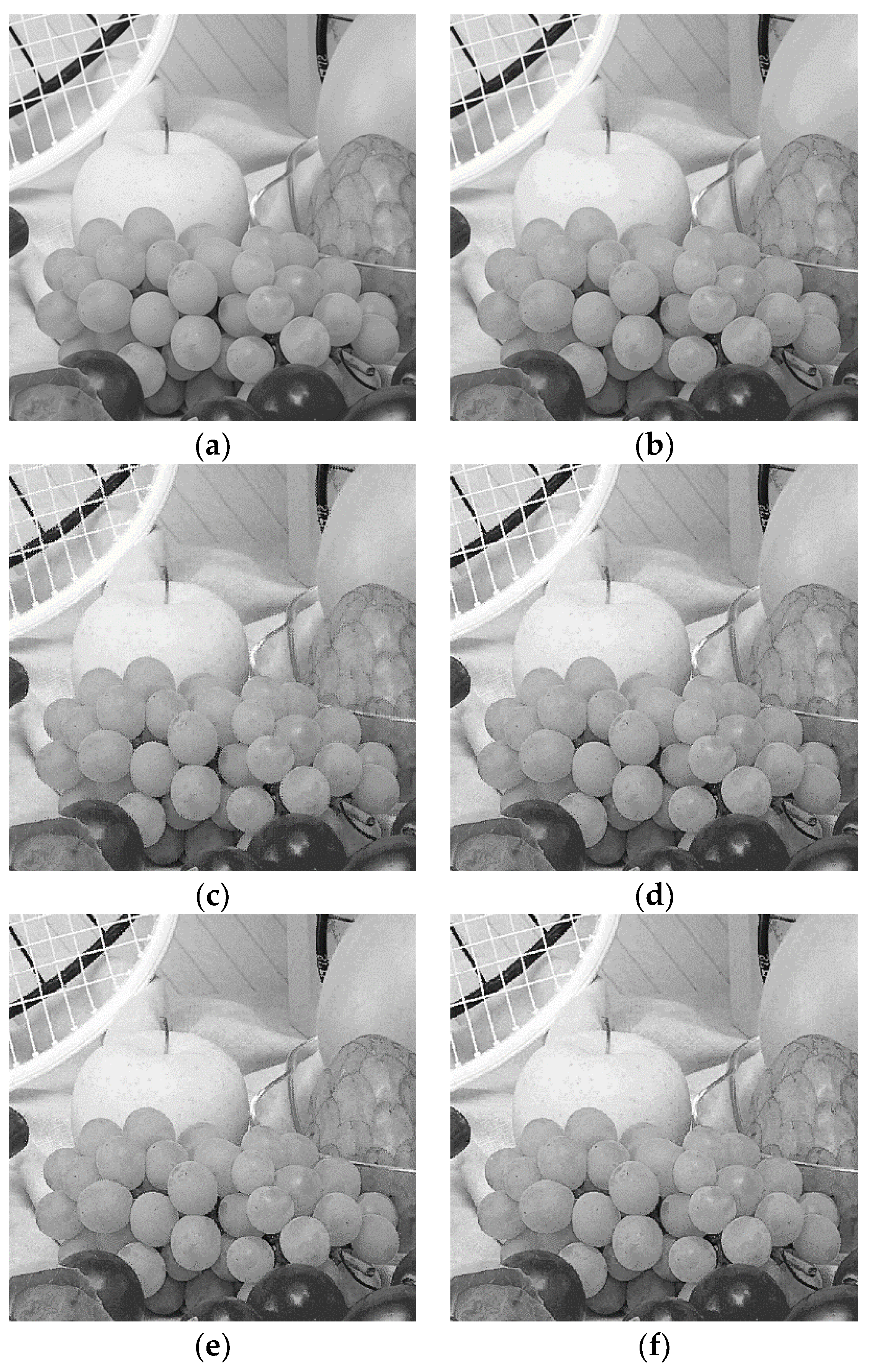
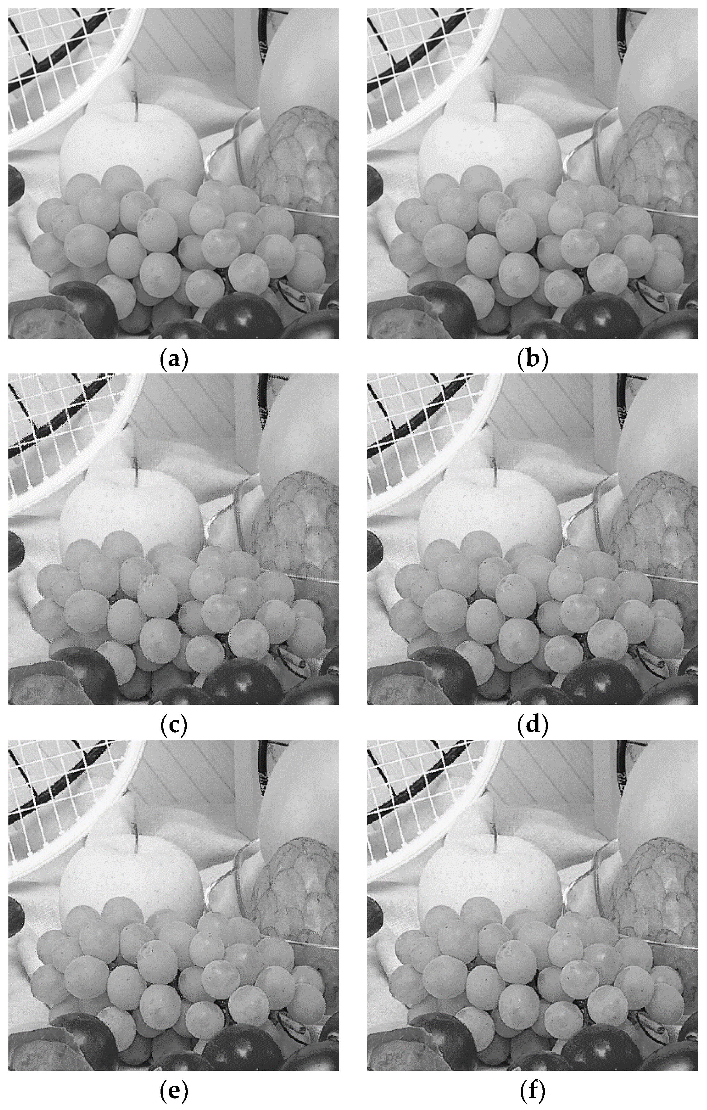
The ODBTC, EDBTC, DDBTC and DDBTC Gaussian utilize the image block processing of size . Figure 11, Figure 12 and Figure 13 show the proposed method performances under Image Set 1 on reducing JPEG false contour over various quality factors, i.e. . As shown in these figures, low quality factor yields unpleasant JPEG decoded image quality indicating with appearing the false contour. The false contour problem can be easily perceived in the grape images. By employing the proposed method, the JPEG false contour can be reduced. In these figures, the DDBTC Gaussian scheme gives the best visual effect on reducing JPEG false contour.
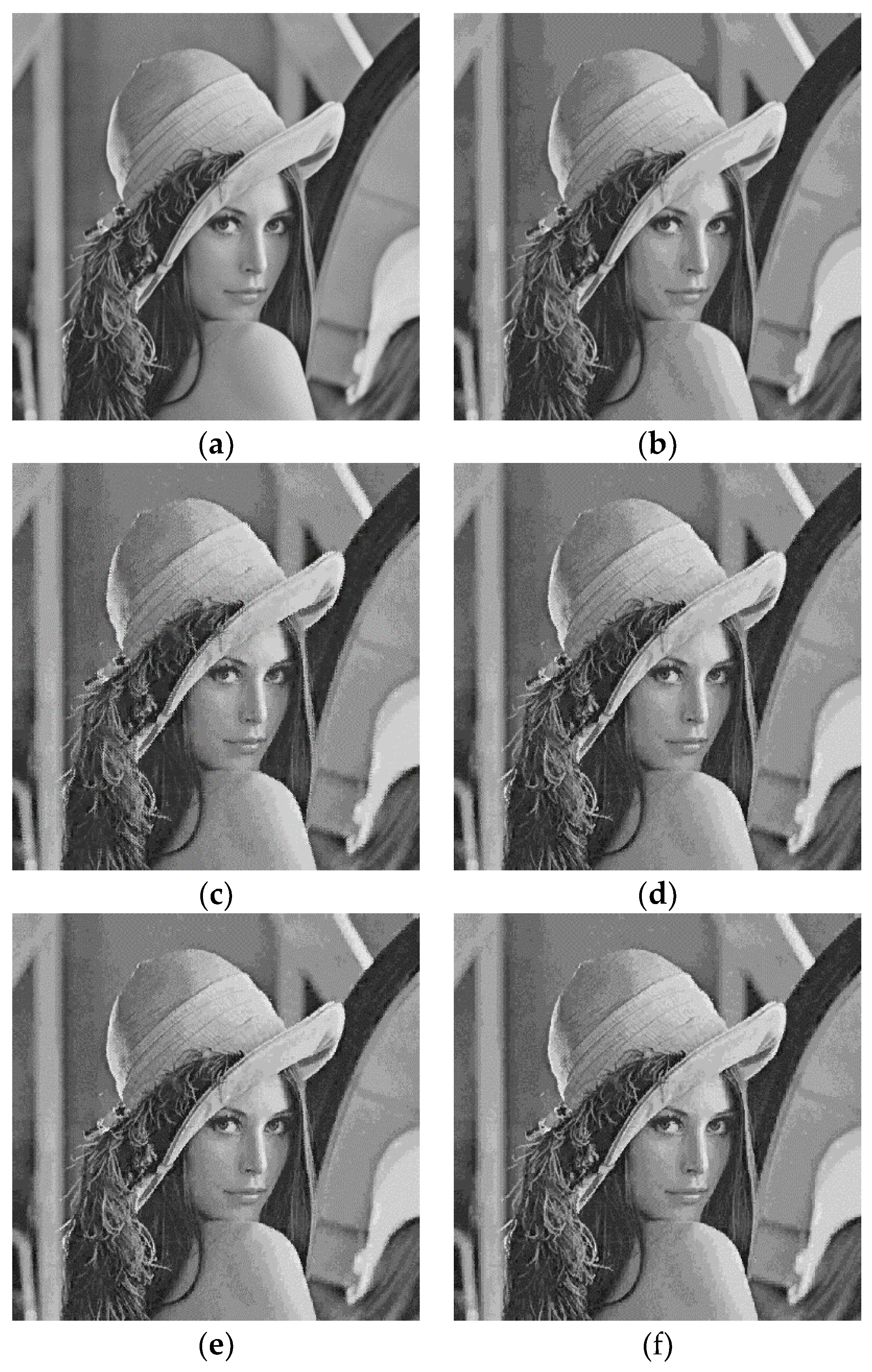
Figure 14, Figure 15 and Figure 16 delivers the proposed method results for Image Set 2 in the JPEG false reduction task. Herein, the JPEG compresses an input image using several quality factors, i.e. . These quality factor induces the false contour. For example, the false contour appears on the Lena shoulder which can be easily seen in these figures. As reported in these figures, the proposed method effectively reduces the JPEG false contour using the HBTC approach. The EDBTC method gives better performance compared to that of ODBTC scheme. Whereas the DDBTC yields better result compared to that of the EDBTC method in suppressing the unpleasant contour. Yet, the DDBTC Gaussian shows the best result among of them. Thus, the proposed method is very effective to reduce the JPEG false contour especially in low quality factor. It broads the usability of HBTC approaches on JPEG image compression.
4.3. Effects of Different Block Sizes
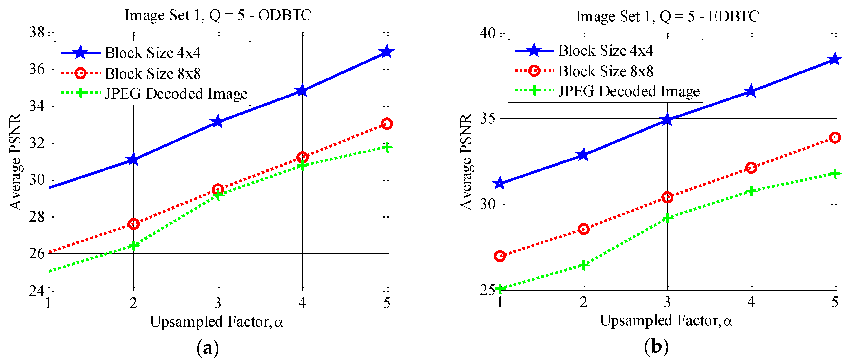
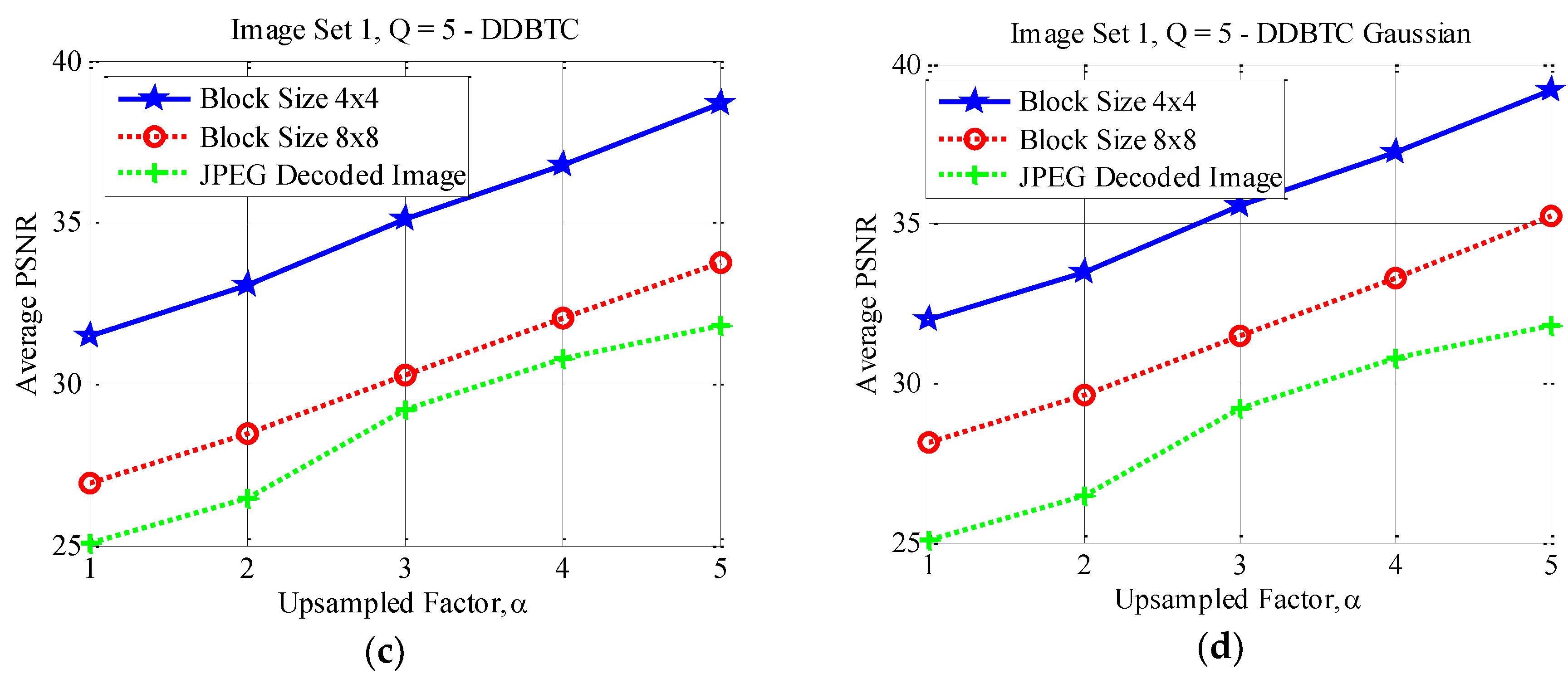
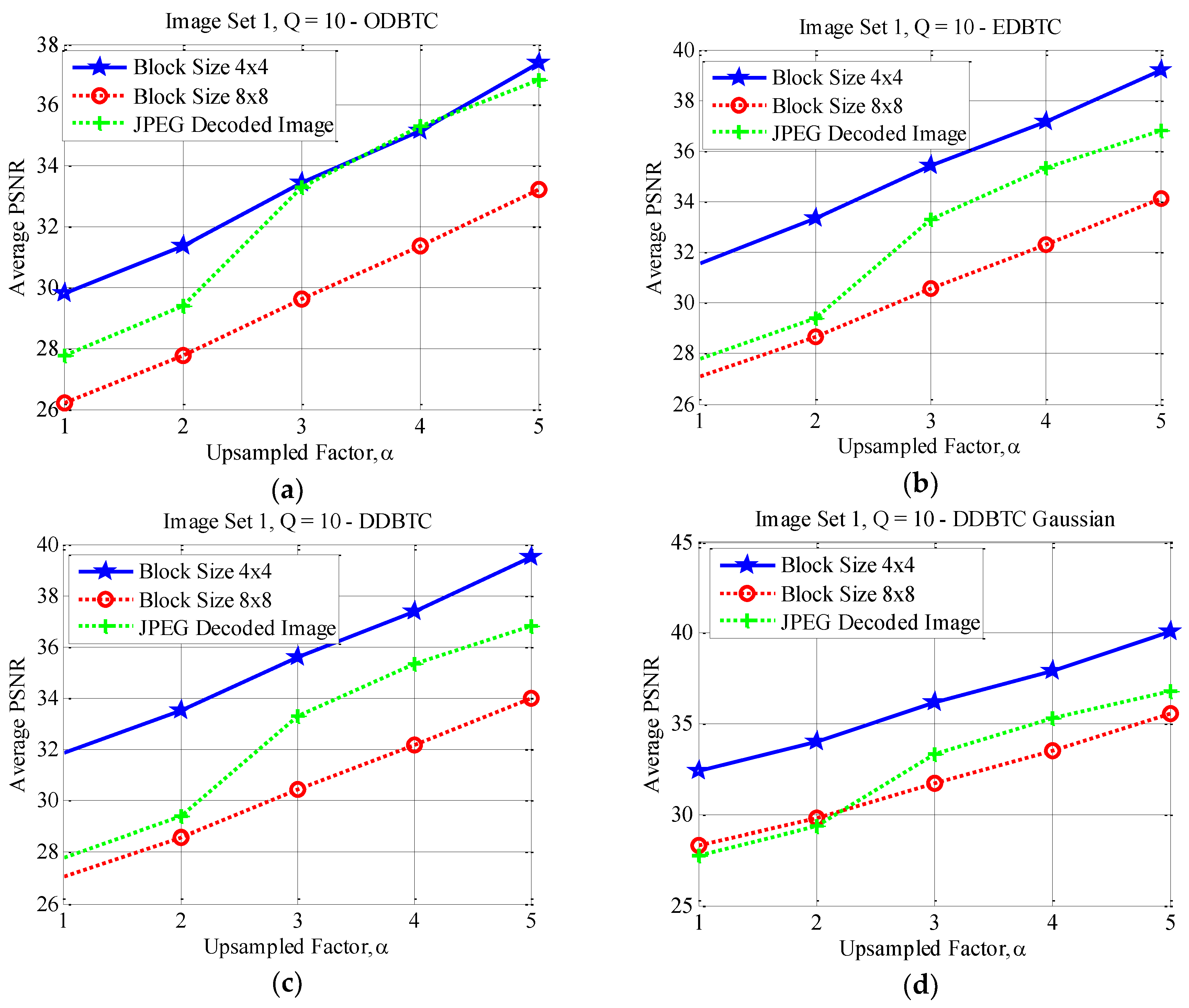
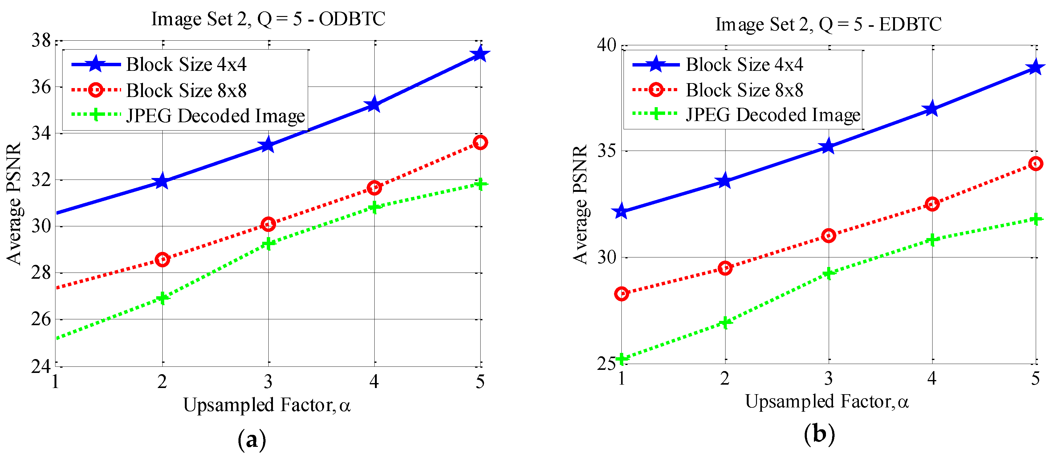
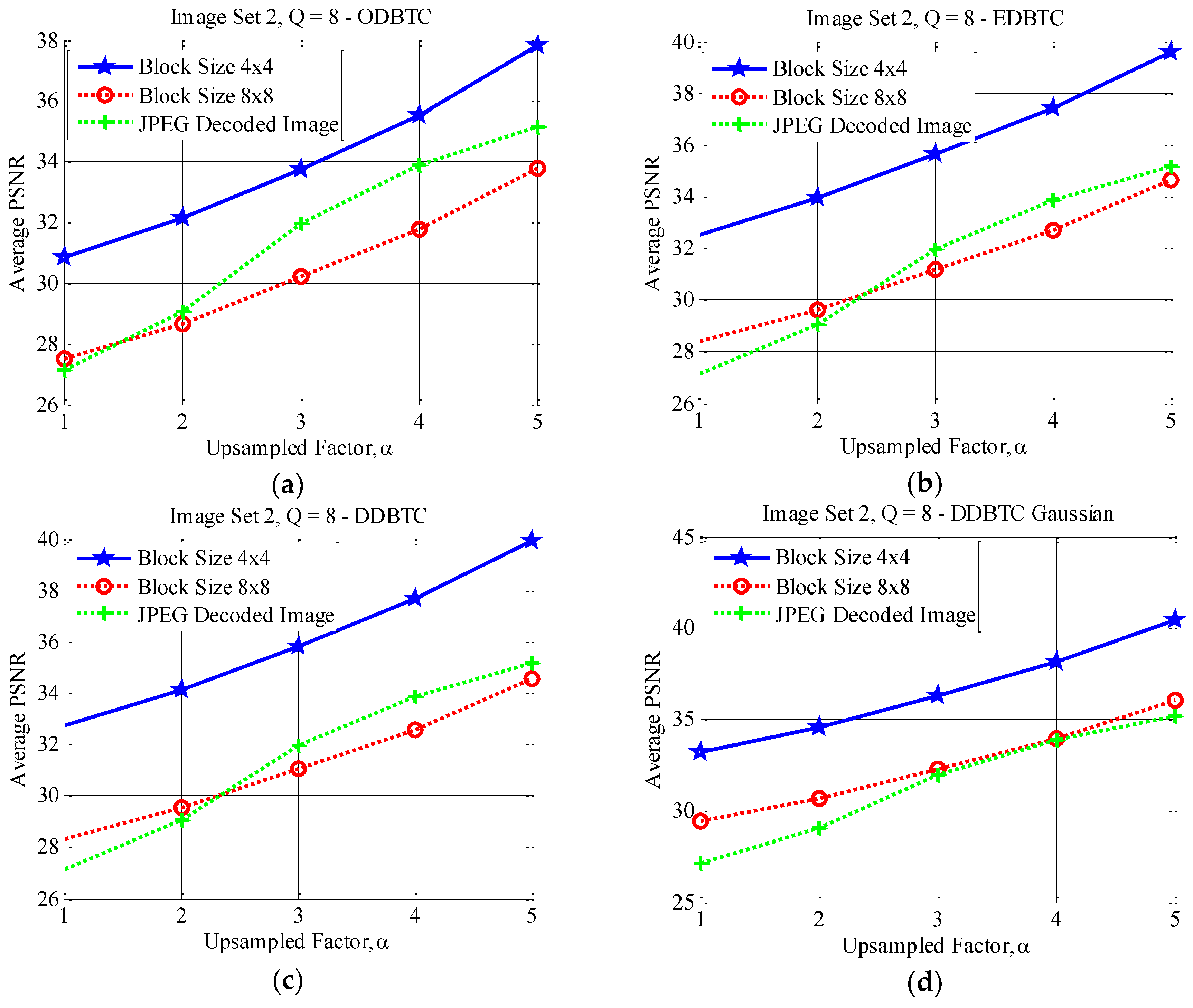
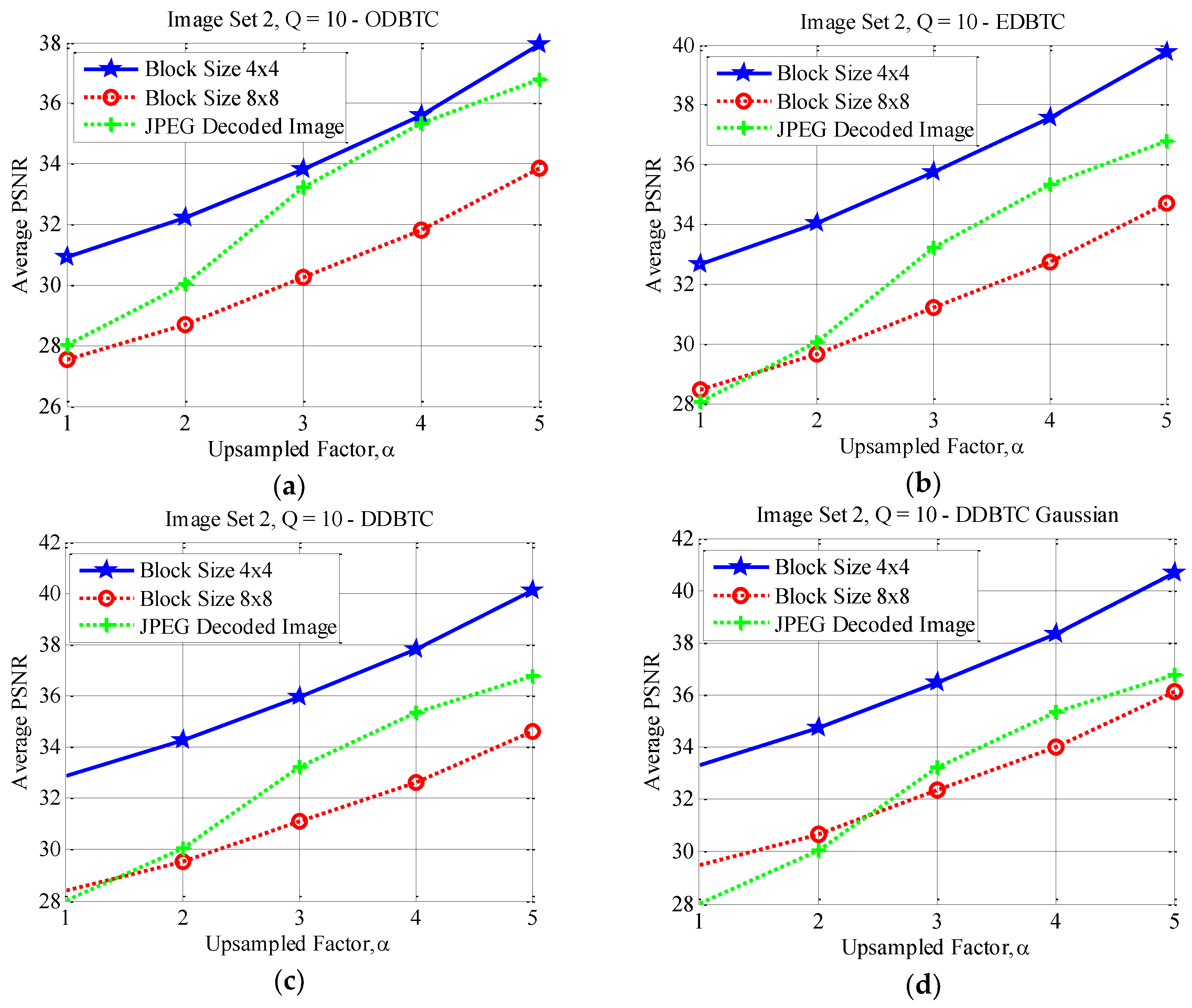
This subsection reports the effect of using different image block sizes. Some experimental results of the proposed method under various image block sizes are detail presented in this subsection. The proposed ODBTC, EDBTC, DDBTC and DDBTC Gaussian utilize the image block size for modifying the DC components. Different image block size yields different performance. Herein, two image block sizes are investigated and compared for the proposed method, i.e. . In this experiment, the proposed method performance is examined in terms of average PSNR values on Image Set 1 and Image Set 2 over two aforementioned image block sizes. All images in Image Set 1 and Image Set 2 are bicubic interpolated using . The quality factors of JPEG image compression are set as .
Figure 17, Figure 18 and Figure 19 show the average PSNR comparison of the proposed method for Image Set 1 under the image block sizes and with different quality factor. As depicted in these figures, the proposed method with yields better performance compared to that of over all JPEG quality factors. For Image Set 2, the proposed method with also gives better performance compared to that of using indicating with higher average PSNR values. These results are confirmed in Figure 20, Figure 21 and Figure 22. Thus, the image block can be regarded as a good parameter setting for the proposed method in reducing JPEG false contour.
4.4. Performance Comparison
The proposed method superiority is further investigated by comparing its performance against the former existing scheme in the JPEG false contour reduction. Herein, the proposed method is compared with the former scheme [15] in terms of average PNSR value. Both methods employ the image block of size . The JPEG quality factor is set as . The comparison is conducted over various bicubic upsampled factor, i.e. over Image Set 1 and Image Set 2.
Table 2 summarizes the performance comparison between the proposed method and former scheme on Image Set 1 over various quality factors. As reported in this table, the proposed method gives the better performance compared to that of [15]. The proposed DDBTC Gaussian scheme yields the best performance for Image Set 1 as indicated with highest PSNR scores over all JPEG quality factors. In addition, higher quality factor also gives better average PSNR since the higher quality factor produces less false contour in JPEG decoded image.
The similar finding also appears on the performance comparison between the proposed method and former scheme under Image Set 2. Table 3 tabulates the average PSNR value comparison between these two methods for Image Set 2. Again, the proposed DDBTC method beats the former scheme performance as indicated with higher average PSNR score. In addition, the proposed DDBTC Gaussian method yields the best performance among the other schemes over various upsampled factors, . From this experiment, it can be concluded that the proposed method is very effective on reducing JPEG false contour with simple and efficient approach. Yet, the proposed method simply modifies the JPEG encoding process, especially for modifying DC components. The proposed method does not require some modification at the decoding process. The modified DC components resulted from the proposed method can be opened with the standard JPEG decoding module.
4.5. JPEG False Contour Reduction for Color Image
The subsection investigates the proposed method effectiveness on JPEG false contour reduction task over color image. Herein, the color image is compressed using JPEG by firstly converting the color image from Red-Green-Blue (RGB) color space into the Luminance-Chrominance (YCbCr) color channel. This approach employs chrominance subsampling before applying the JPEG, i.e. DCT process and quantization. Similar to the grayscale processing, the JPEG false contour reduction modifies the DC-components of color image using the proposed HBTC method.
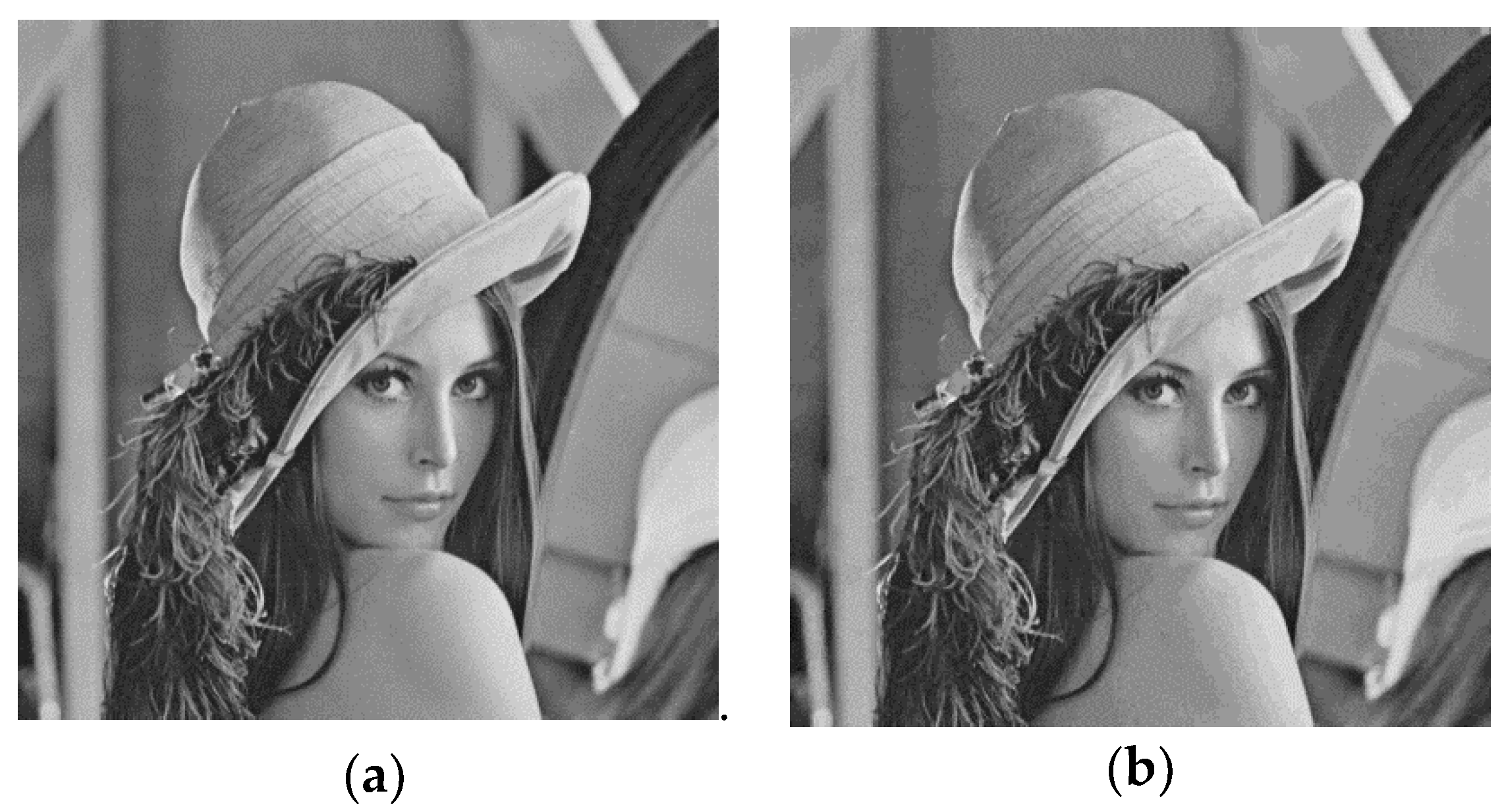
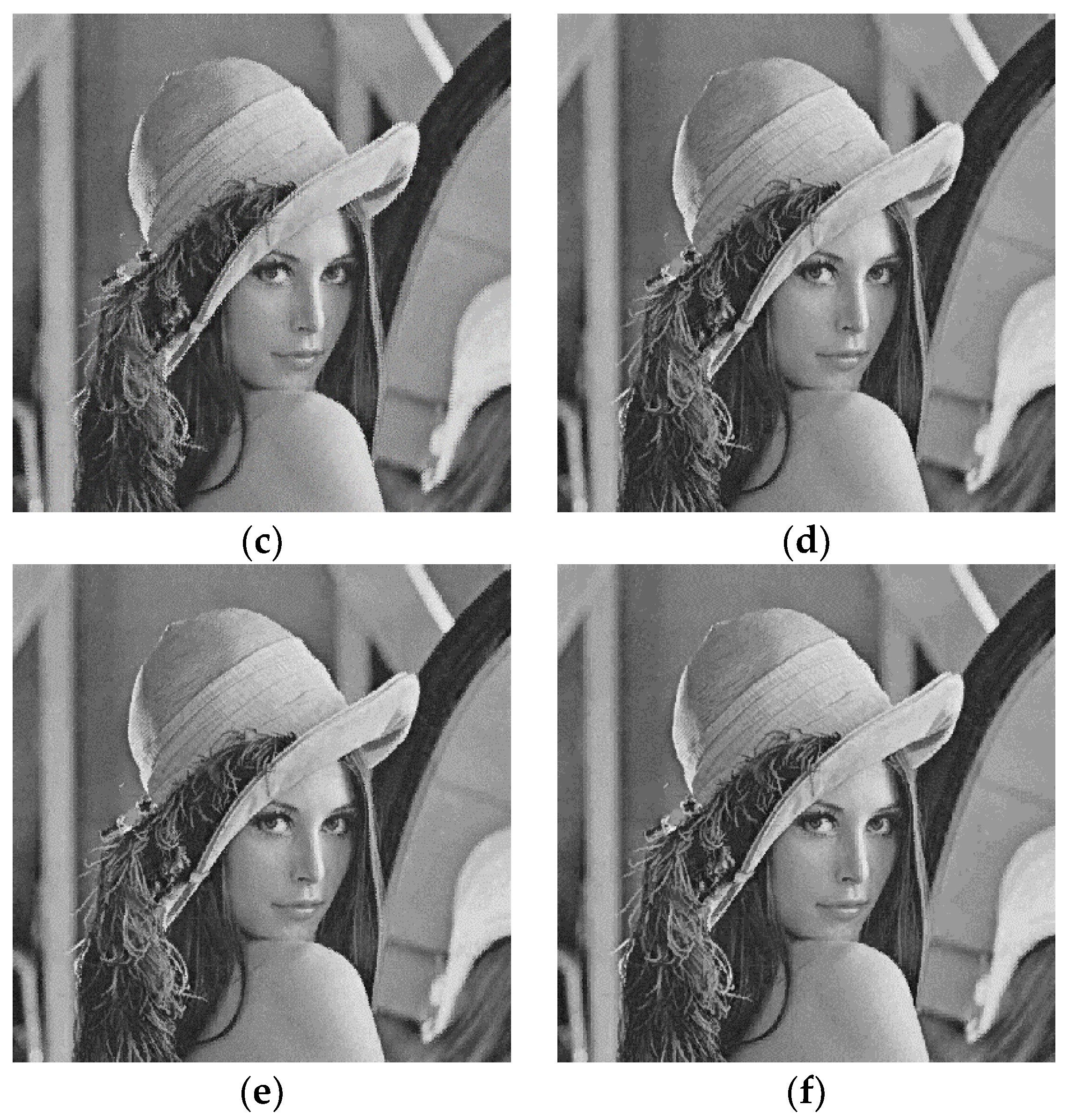
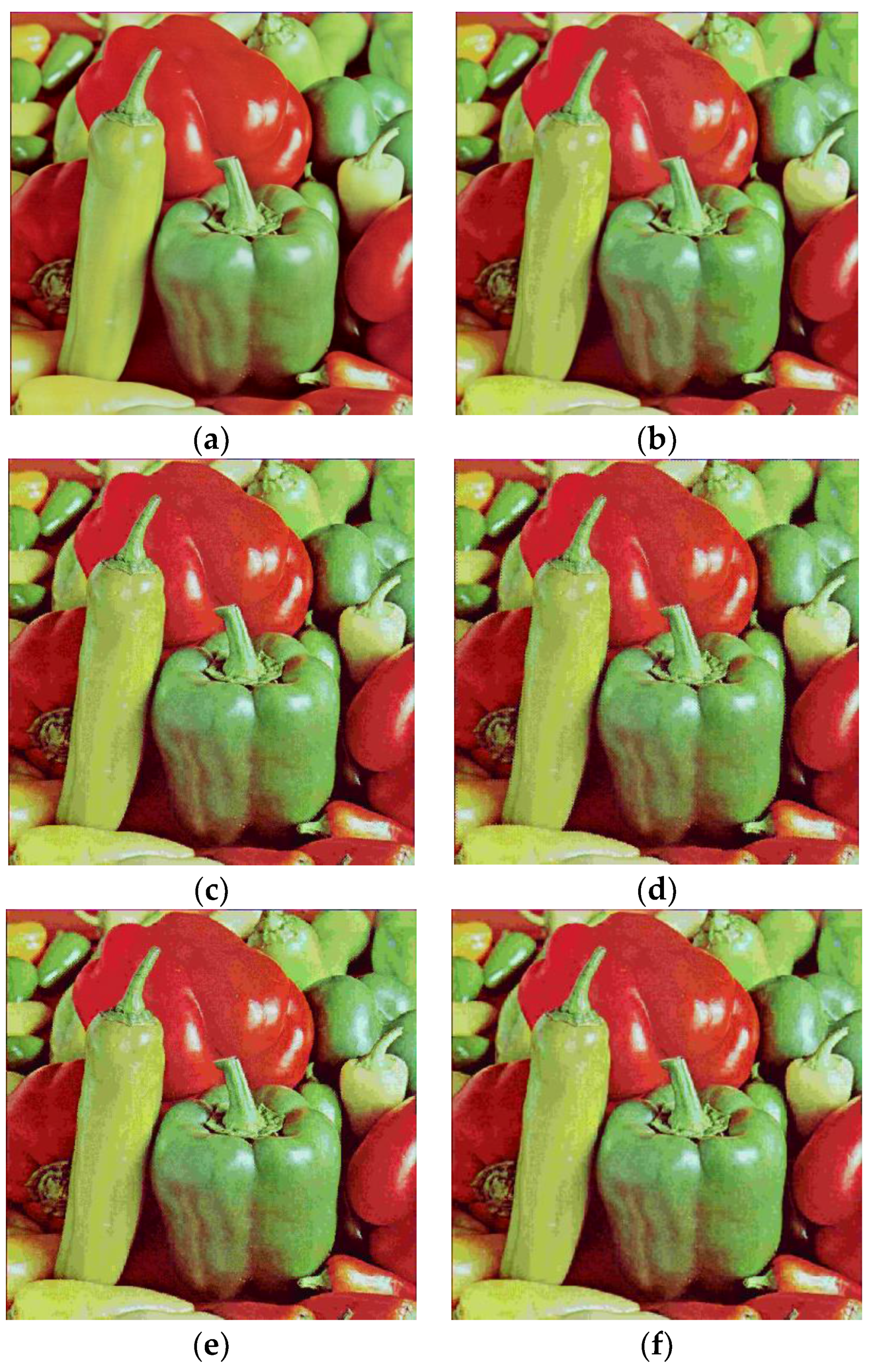
Figure 23 reports the JPEG false contour reduction using the proposed HBTC method. The JPEG quality factor is set as to produce the false contour on the decoded image. Figure 23a,b show the input image and the corresponding JPEG decoded image, respectively. As shown in these figures, the JPEG compression yields unpleasant decoded image in which the false contour can be easily perceived as shown in Figure 23b. Figure 23c–f deliver some JPEG false contour reduction under various HBTC techniques, i.e. (c) ODBTC; (d) EDBTC; (e) DDBTC; and (f) DDBTC Gaussian. The HBTC approaches effectively suppress the JPEG false contour for color image by modifying the DC components. Thus, the proposed method offers a promising result on JPEG false contour for grayscale and color image with effective and efficient approaches. The proposed method can be also directly applied to the other color spaces.
5. Conclusions
An effective way for reducing the JPEG false contour has been presented in this paper. It exploits the HBTC usability for modifying the DCT components of all image blocks. The HBTC produces visual illumination which is very useful on suppressing the JPEG false contour. As reported in experimental results, the proposed method offers promising results on JPEG decoded image. This paper proves that HBTC is not only suitable for half toning and compressing an image but it is also powerful for subtracting the unpleasant false contour noise.
For the future works, some additional techniques can be carried out to bring the proposed method into the color image and video processing. The performance of the proposed method can be extended into the other color spaces such as Hue-Saturation-Intensity (HSI), Luminance-Chrominance (YCbCr), CIE 1931 XYZ color space, CIELUV, CIEUVW, CIELAB, etc., to further investigate the proposed method usability. In this current work, the HBTC simply employs extreme quantizers for generating the visual illumination. The number of HBTC extreme quantizers can be increased, not only two, to improve the proposed method performance. It can be viewed to bring the multi toning approach for HBTC. In addition, a slight modification should be carried out for the proposed method on dealing with the wavelet-based JPEG image compression. Thus, the proposed method can work well on several types of JPEG compression, not only DCT-based JPEG. Special consideration should be taken into account on implementing the proposed method for the video processing. Herein, the proposed method can be simply performed on image sequences of video file or modified under visual effect of video processing.
Acknowledgments
This work was fully supported by Universitas Sebelas Maret (UNS), Surakarta, Indonesia under the research grant for international collaboration, and Soft Computing Research Group (SCRG), M08101348.
Author Contributions
Both authors have contributed, conceived and designed the experiments; performed the experiments; analyzed the data; contributed reagents/materials/analysis tools; and wrote the paper.
Conflicts of Interest
The authors declare no conflict of interest.
References
- Guo, J.M. High efficiency ordered dither block truncation with dither array LUT and its scalable coding application. Digit. Signal Process. 2010, 20, 97–110. [Google Scholar] [CrossRef]
- Guo, J.M. Improved block truncation coding using modified error diffusion. Electron. Lett. 2008, 44, 7. [Google Scholar] [CrossRef]
- Guo, J.M.; Liu, Y.F. Improved Block Truncation Coding using Optimized Dot Diffusion. IEEE Trans. Image Process. 2014, 23, 1269–1275. [Google Scholar]
- Guo, J.M.; Prasetyo, H.; Lee, H.; Yao, C.C. Image retrieval using indexed histogram of void-and-cluster block truncation coding. Signal Process. 2016, 123, 143–156. [Google Scholar] [CrossRef]
- Guo, J.M.; Wu, M.F.; Kang, Y.C. Watermarking in conjugate ordered dither block truncation coding images. Signal Process. 2009, 89, 1864–1882. [Google Scholar] [CrossRef]
- Guo, J.M.; Prasetyo, H.; Su, H.S. Image indexing using the color and bit pattern feature fusion. J. Vis. Commun. Image Represent. 2013, 24, 1360–1379. [Google Scholar] [CrossRef]
- Guo, J.M.; Prasetyo, H. Content-Based Image Retrieval Using Features Extracted From Halftoning-Based Block Truncation Coding. IEEE Trans. Image Process. 2015, 24, 1010–1024. [Google Scholar] [PubMed]
- Guo, J.M.; Prasetyo, H.; Chen, J.H. Content-based image retrieval using error diffusion block truncation coding features. IEEE Trans. Circuits Syst. Video Technol. 2015, 25, 466–481. [Google Scholar]
- Guo, J.M.; Prasetyo, H.; Wang, N.J. Effective image retrieval system using dot-diffused block truncation coding features. IEEE Trans. Multimed. 2015, 17, 1576–1590. [Google Scholar] [CrossRef]
- Liu, Y.F.; Guo, J.M.; Lee, J.D. Inverse halftoning based on the Bayesian theorem. IEEE Trans. Image Process. 2011, 20, 1077–1084. [Google Scholar] [PubMed]
- Liu, Y.F.; Guo, J.M. Dot-diffused halftoning with improved homogeneity. IEEE Trans. Image Process. 2015, 24, 4581–4591. [Google Scholar] [CrossRef] [PubMed]
- Liu, Y.F.; Guo, J.M. New class tilling design for dot-diffused halftoning. IEEE Trans. Image Process. 2013, 22, 1199–1208. [Google Scholar] [CrossRef] [PubMed]
- Guo, J.M.; Liu, Y.F. High capacity data hiding for error-diffused block truncation coding. IEEE Trans. Image Process. 2012, 21, 4808–4818. [Google Scholar] [PubMed]
- Guo, J.M.; Liu, Y.F. Halftone-image security improving using overall minimal-error searching. IEEE Trans. Image Process. 2011, 20, 2800–2812. [Google Scholar] [PubMed]
- Guo, J.M.; Hsia, C.H.; Chang, C.H. JPEG false contour reduction using error diffusion. Inform. Process. Lett. 2015, 115, 403–407. [Google Scholar] [CrossRef]
Figure 1.
Example of JPEG compression with : (a) input image block ; (b) quantization matrix ; (c) encoded image ; and (d) decoded image.
Figure 1.
Example of JPEG compression with : (a) input image block ; (b) quantization matrix ; (c) encoded image ; and (d) decoded image.

Figure 2.
Schematic diagram of the proposed method.

Figure 3.
Example of Floyd-Steinberg error kernel.

Figure 4.
Examples of (a) ODBTC dither array, and its scaled version (stored as LUT for latter usage): (b) ; (c) ; (d) ; (e) ; and (f) .
Figure 4.
Examples of (a) ODBTC dither array, and its scaled version (stored as LUT for latter usage): (b) ; (c) ; (d) ; (e) ; and (f) .
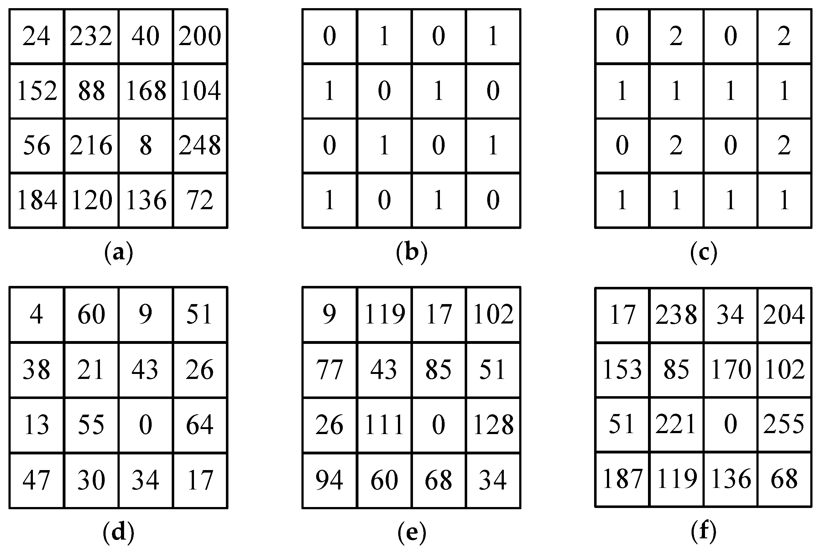
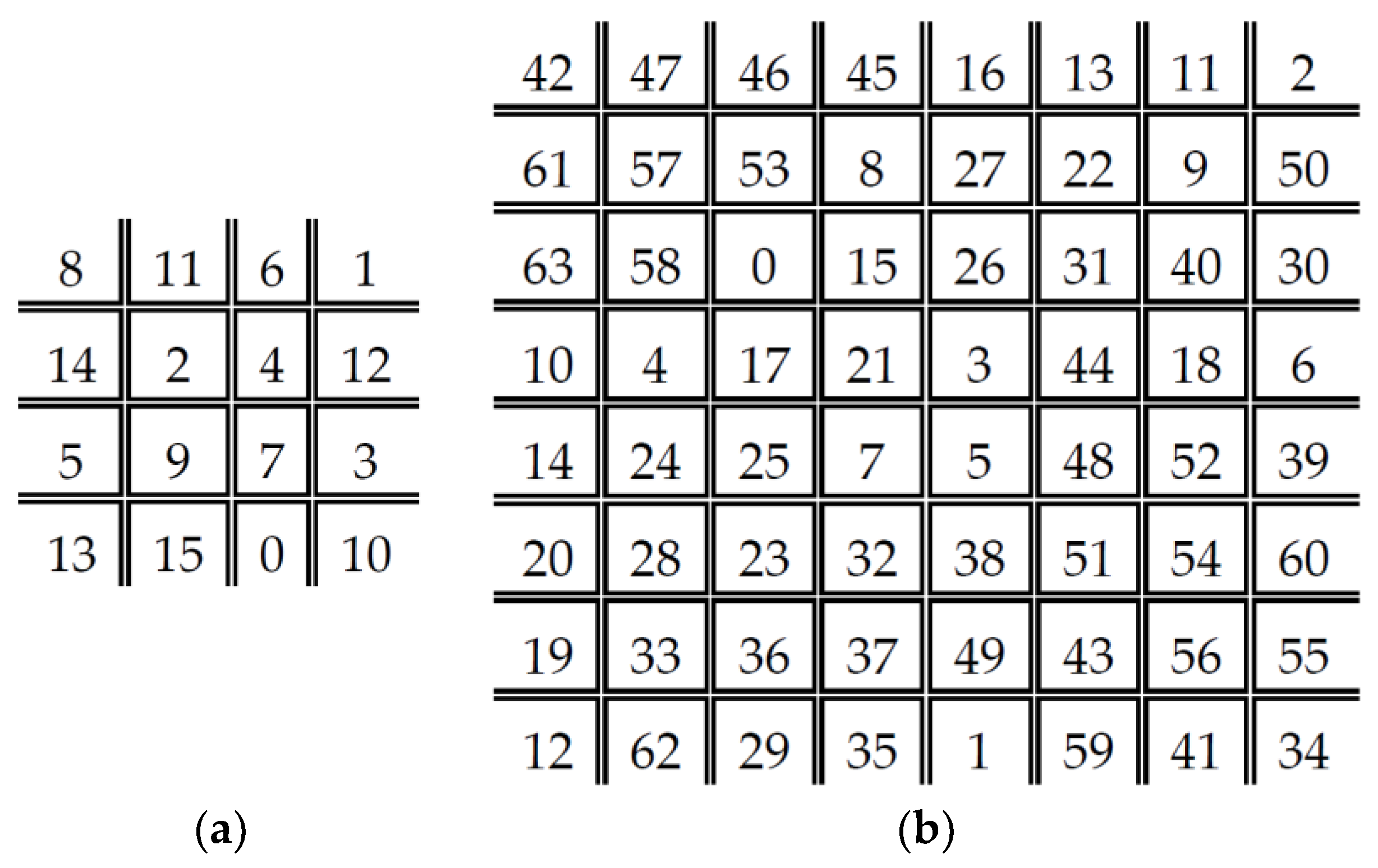
Figure 5.
DDBTC class matrix for image block size: (a) ; and (b) .

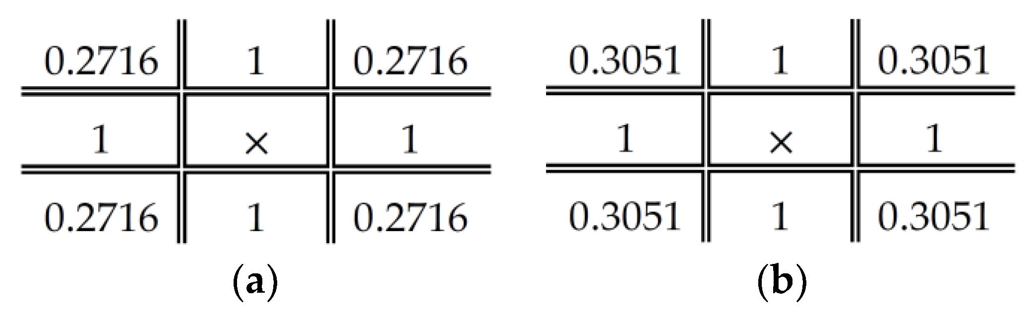
Figure 6.
DDBTC diffused kernel for image block size: (a); and (b) .

Figure 7.
DDBTC Gaussian diffused kernel.

Figure 8.
Numerical examples of HBTC process: (a) input image; (b–e) are using EDBTC, ODBTC, DDBTC and DDBTC Gaussian, respectively.
Figure 8.
Numerical examples of HBTC process: (a) input image; (b–e) are using EDBTC, ODBTC, DDBTC and DDBTC Gaussian, respectively.

Figure 9.
A set of images, named as Image Set 1, used to validate proposed method performance.

Figure 10.
A set of images, named as Image Set 2, for experiment.

Figure 11.
Visual investigation on Image Set 1 with quality factor : (a) input image; (b) JPEG decoded image; (c) ODBTC; (d) EDBTC; (e) DDBTC; and (f) DDBTC Gaussian method.
Figure 11.
Visual investigation on Image Set 1 with quality factor : (a) input image; (b) JPEG decoded image; (c) ODBTC; (d) EDBTC; (e) DDBTC; and (f) DDBTC Gaussian method.


Figure 12.
Visual investigation on Image Set 1 with quality factor : (a) input image; (b) JPEG decoded image; (c) ODBTC; (d) EDBTC; (e) DDBTC; and (f) DDBTC Gaussian method.
Figure 12.
Visual investigation on Image Set 1 with quality factor : (a) input image; (b) JPEG decoded image; (c) ODBTC; (d) EDBTC; (e) DDBTC; and (f) DDBTC Gaussian method.

Figure 13.
Visual investigation on Image Set 1 with quality factor : (a) input image; (b) JPEG decoded image; (c) ODBTC; (d) EDBTC; (e) DDBTC; and (f) DDBTC Gaussian method.
Figure 13.
Visual investigation on Image Set 1 with quality factor : (a) input image; (b) JPEG decoded image; (c) ODBTC; (d) EDBTC; (e) DDBTC; and (f) DDBTC Gaussian method.

Figure 14.
Visual investigation on Image Set 2 with quality factor : (a) input image; (b) JPEG decoded image; (c) ODBTC; (d) EDBTC; (e) DDBTC; and (f) DDBTC Gaussian method.
Figure 14.
Visual investigation on Image Set 2 with quality factor : (a) input image; (b) JPEG decoded image; (c) ODBTC; (d) EDBTC; (e) DDBTC; and (f) DDBTC Gaussian method.

Figure 15.
Visual investigation on Image Set 2 with quality factor : (a) input image; (b) JPEG decoded image; (c) ODBTC; (d) EDBTC; (e) DDBTC; and (f) DDBTC Gaussian method.
Figure 15.
Visual investigation on Image Set 2 with quality factor : (a) input image; (b) JPEG decoded image; (c) ODBTC; (d) EDBTC; (e) DDBTC; and (f) DDBTC Gaussian method.


Figure 16.
Visual investigation on Image Set 2 with quality factor : (a) input image; (b) JPEG decoded image; (c) ODBTC; (d) EDBTC; (e) DDBTC; and (f) DDBTC Gaussian method.
Figure 16.
Visual investigation on Image Set 2 with quality factor : (a) input image; (b) JPEG decoded image; (c) ODBTC; (d) EDBTC; (e) DDBTC; and (f) DDBTC Gaussian method.
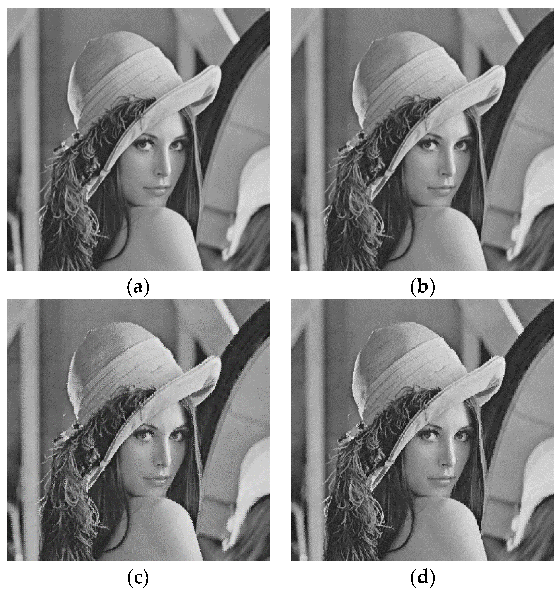
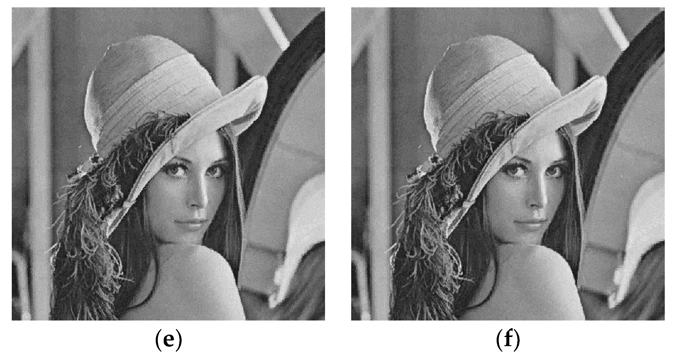
Figure 17.
Effect of image block sizes on Image Set 1 with over (a) ODBTC; (b) EDBTC; (c) DDBTC; and (d) DDBTC Gaussian scheme.
Figure 17.
Effect of image block sizes on Image Set 1 with over (a) ODBTC; (b) EDBTC; (c) DDBTC; and (d) DDBTC Gaussian scheme.


Figure 18.
Effect of image block sizes on Image Set 1 with over (a) ODBTC; (b) EDBTC; (c) DDBTC; and (d) DDBTC Gaussian scheme.
Figure 18.
Effect of image block sizes on Image Set 1 with over (a) ODBTC; (b) EDBTC; (c) DDBTC; and (d) DDBTC Gaussian scheme.
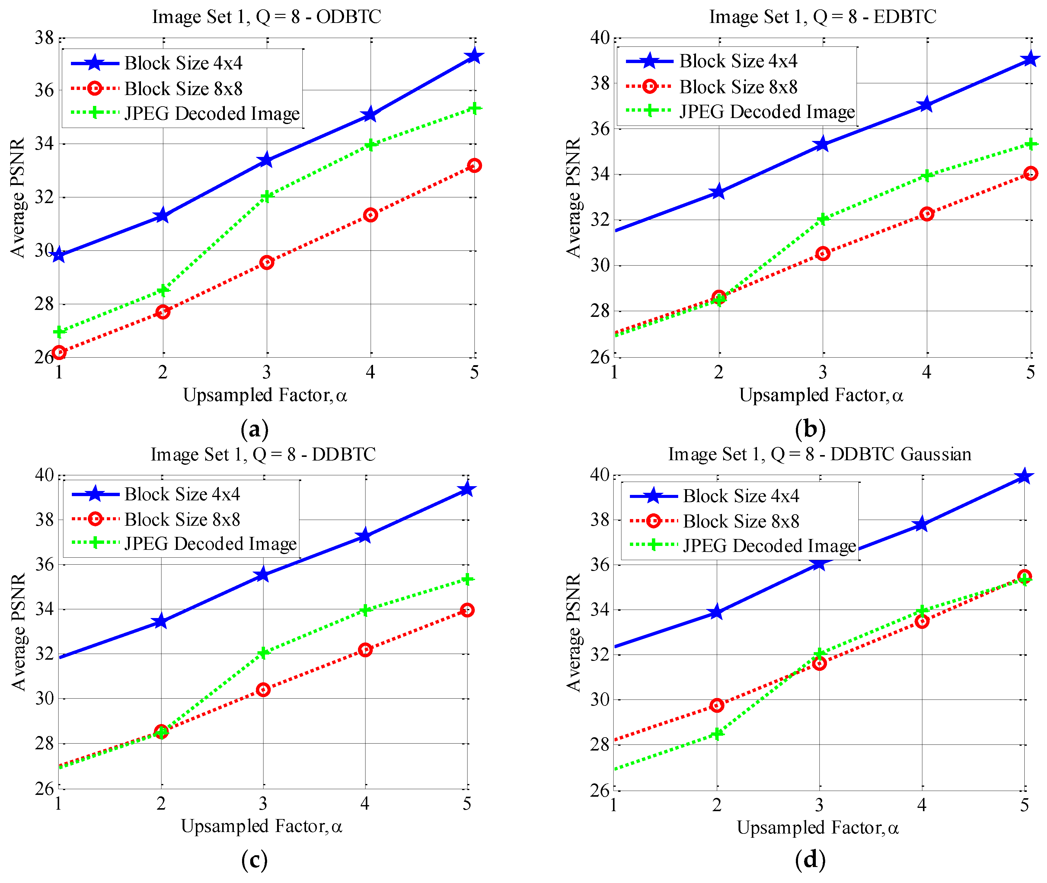
Figure 19.
Effect of image block sizes on Image Set 1 with over (a) ODBTC; (b) EDBTC; (c) DDBTC; and (d) DDBTC Gaussian scheme.
Figure 19.
Effect of image block sizes on Image Set 1 with over (a) ODBTC; (b) EDBTC; (c) DDBTC; and (d) DDBTC Gaussian scheme.

Figure 20.
Effect of image block sizes on Image Set 2 with over (a) ODBTC; (b) EDBTC; (c) DDBTC; and (d) DDBTC Gaussian scheme.
Figure 20.
Effect of image block sizes on Image Set 2 with over (a) ODBTC; (b) EDBTC; (c) DDBTC; and (d) DDBTC Gaussian scheme.

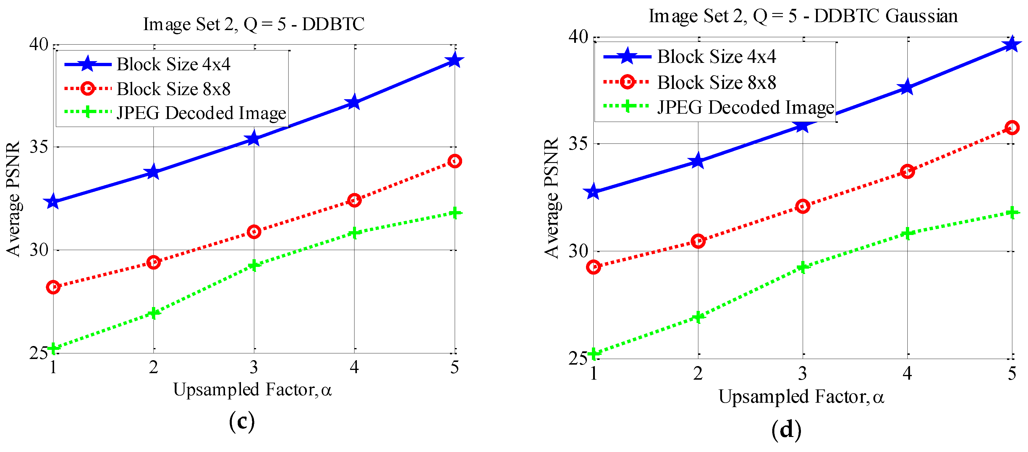
Figure 21.
Effect of image block sizes on Image Set 2 with over (a) ODBTC; (b) EDBTC; (c) DDBTC; and (d) DDBTC Gaussian scheme.
Figure 21.
Effect of image block sizes on Image Set 2 with over (a) ODBTC; (b) EDBTC; (c) DDBTC; and (d) DDBTC Gaussian scheme.

Figure 22.
Effect of image block sizes on Image Set 2 with over (a) ODBTC; (b) EDBTC; (c) DDBTC; and (d) DDBTC Gaussian scheme.
Figure 22.
Effect of image block sizes on Image Set 2 with over (a) ODBTC; (b) EDBTC; (c) DDBTC; and (d) DDBTC Gaussian scheme.

Figure 23.
Result of JPEG false contour reduction on color image with quality factor : (a) input image; (b) JPEG decoded image. The reconstructed images using: (c) ODBTC; (d) EDBTC; (e) DDBTC; and (f) DDBTC Gaussian methods.
Figure 23.
Result of JPEG false contour reduction on color image with quality factor : (a) input image; (b) JPEG decoded image. The reconstructed images using: (c) ODBTC; (d) EDBTC; (e) DDBTC; and (f) DDBTC Gaussian methods.


Table 1.
Summary of key aspects over various HBTC techniques.
| HBTC Methods | Key Aspects of Algorithm |
|---|---|
| EDBTC | Employing the error kernel as shown in Figure 3 |
| ODBTC | Utilizing the dither arrays as shown in Figure 4 |
| DDBTC | Exploiting the class matrix and diffused kernel as given in Figure 5 and Figure 6, respectively |
| DDBTC Gaussian | Combining the class matrix as shown in Figure 5 with Gaussian diffused kernel in Figure 7 |
Table 2.
PSNR Comparison on Image Set 1.
| Quality Factor | Downsampled Factor | JPEG Decoded Image | ODBTC | EDBTC [15] | DDBTC | DDBTC Gaussian |
|---|---|---|---|---|---|---|
| 25.07 | 29.59 | 31.21 | 31.49 | 31.99 | ||
| 26.44 | 31.08 | 32.88 | 33.05 | 33.49 | ||
| 29.19 | 33.11 | 34.91 | 35.10 | 35.57 | ||
| 30.79 | 34.82 | 36.60 | 36.80 | 37.25 | ||
| 31.78 | 36.88 | 38.45 | 38.69 | 39.18 | ||
| Average | 28.66 | 33.09 | 34.81 | 35.03 | 35.49 | |
| 26.93 | 29.79 | 31.51 | 31.82 | 32.35 | ||
| 28.49 | 31.30 | 33.23 | 33.41 | 33.89 | ||
| 32.05 | 33.36 | 35.30 | 35.51 | 36.03 | ||
| 33.97 | 35.10 | 37.03 | 37.25 | 37.76 | ||
| 35.34 | 37.28 | 39.04 | 39.31 | 39.88 | ||
| Average | 31.36 | 33.37 | 35.22 | 35.46 | 35.98 | |
| 27.78 | 29.82 | 31.57 | 31.89 | 32.43 | ||
| 29.38 | 31.38 | 33.34 | 33.54 | 34.02 | ||
| 33.32 | 33.43 | 35.41 | 35.62 | 36.16 | ||
| 35.32 | 35.17 | 37.15 | 37.37 | 37.90 | ||
| 36.82 | 37.39 | 39.20 | 39.49 | 40.08 | ||
| Average | 32.53 | 33.44 | 35.34 | 35.58 | 36.12 |
Table 3.
PSNR Comparison on Image Set 2.
| Quality Factor | Downsampled Factor | JPEG Decoded Image | ODBTC | EDBTC [15] | DDBTC | DDBTC Gaussian |
|---|---|---|---|---|---|---|
| 25.20 | 30.58 | 32.15 | 32.33 | 32.73 | ||
| 26.91 | 31.89 | 33.56 | 33.75 | 34.16 | ||
| 29.26 | 33.46 | 35.21 | 35.40 | 35.83 | ||
| 30.82 | 35.20 | 36.94 | 37.16 | 37.59 | ||
| 31.81 | 37.37 | 38.90 | 39.19 | 39.62 | ||
| Average | 28.80 | 33.70 | 35.35 | 35.57 | 35.99 | |
| 27.13 | 30.86 | 32.54 | 32.74 | 33.18 | ||
| 29.06 | 32.14 | 33.94 | 34.15 | 34.59 | ||
| 31.96 | 33.74 | 35.63 | 35.83 | 36.32 | ||
| 33.89 | 35.52 | 37.44 | 37.68 | 38.17 | ||
| 35.17 | 37.83 | 39.57 | 39.91 | 40.42 | ||
| Average | 31.44 | 34.02 | 35.82 | 36.06 | 36.54 | |
| 28.04 | 30.94 | 32.66 | 32.88 | 33.32 | ||
| 30.05 | 32.22 | 34.06 | 34.27 | 34.73 | ||
| 33.23 | 33.82 | 35.75 | 35.96 | 36.46 | ||
| 35.34 | 35.61 | 37.57 | 37.83 | 38.33 | ||
| 36.79 | 37.96 | 39.78 | 40.13 | 40.67 | ||
| Average | 32.69 | 34.11 | 35.96 | 36.21 | 36.70 |
© 2018 by the authors. Licensee MDPI, Basel, Switzerland. This article is an open access article distributed under the terms and conditions of the Creative Commons Attribution (CC BY) license (http://creativecommons.org/licenses/by/4.0/).
Share and Cite
MDPI and ACS Style
Prasetyo, H.; Kurniawan, H. Reducing JPEG False Contour Using Visual Illumination. Information 2018, 9, 41. https://doi.org/10.3390/info9020041
AMA Style
Prasetyo H, Kurniawan H. Reducing JPEG False Contour Using Visual Illumination. Information. 2018; 9(2):41. https://doi.org/10.3390/info9020041
Chicago/Turabian StylePrasetyo, Heri, and Hendra Kurniawan. 2018. "Reducing JPEG False Contour Using Visual Illumination" Information 9, no. 2: 41. https://doi.org/10.3390/info9020041
Note that from the first issue of 2016, this journal uses article numbers instead of page numbers. See further details here.