1. Introduction
Due to the openness of the wireless transmission medium, information faces serious security threats in wireless networks. Physical layer security, based on information theory, utilizes the physical characteristics of channels to achieve secure transmission [
1,
2]. Secrecy rate is an important parameter to measure the confidential performance of a secure system [
3]. Much literature has showed that relay cooperation can enhance the performance of physical layer security effectively. The cooperation protocols include amplify-and-forward (AF), decode-and-forward (DF), and cooperative jamming (CJ). In [
4], the security performances of three cooperation protocols have been analyzed when there are one or more eavesdroppers. In [
5], AF and artificial noise (AN) are simultaneously employed to improve the secrecy rate under the condition of imperfect channel state information (CSI). In [
6], multiple relays are used, one of which is selected for CJ relay and others for AF relay. In [
7], two cooperation schemes are proposed in AF relay networks, in which jamming signals can be sent by the destination or a relay.
With the rapid development of wireless network technology, energy consumption in wireless communication networks is also increasing. Energy harvesting is an effective way to prolong the lifetime of wireless nodes. Furthermore, wireless energy transmission is a method to realize energy harvesting and overcome the limitation of energy stored in the battery of a node [
8]. Some references have researched the application of wireless energy transmission in relay networks, e.g., [
9,
10,
11,
12]. In [
9,
10], an energy cooperation protocol is proposed to promote throughput. In [
11], a multi-antenna relay uses different antennas to receive information and harvest energy simultaneously. The throughput maximization of a wireless powered communication network with cooperation is studied in [
12].
The issue of the secure information transmission also exists in energy harvesting networks, and some researchers have studied the physical layer security in them. Two kinds of receivers, i.e., energy receiver and information receiver, are considered in [
13,
14] and [
15]. In these articles, energy and secrecy information are transmitted simultaneously, and energy receivers are treated as eavesdroppers. Some strategies of optimizing secrecy rates have been proposed when the CSIs are both perfect and imperfect. Ref. [
16] is an overview of the security problem in wireless powered systems, and the physical security techniques for wireless information and power transfer in relaying systems are reviewed. The security problem in wireless powered relaying systems is studied in [
17,
18]. Ref. [
17] focuses on the beamforming of signal and artificial noise. Ref. [
18] studies the wireless transmission for both secure information and power in a large-scale relaying system with imperfect CSI.
In this paper, we focus on the physical layer security in an energy harvesting relay network. There are two receivers in the network, and the information sent to a receiver needs to be kept secret from the other receiver, so each is the eavesdropper of the other. When there are some obstacles between the source and the receivers, since no direct communication link exists, the information should be forwarded by a relay. The power supply of the relay is limited because of its location, so it needs to harvest energy from the received RF signals to increase the forwarding power. In our scheme, the relay’s antennas are divided into two groups, with one group amplifying and forwarding the source’s signal, and the other converting the received signal to energy for the forwarding. With the constraint of the source transmitting power, we propose a low complexity antenna grouping scheme, and optimize the beamforming vector of AF to achieve the maximal secrecy rate.
The remainder of this paper is organized as follows. The second section describes the system model. In the third section, we give the mathematical model of the optimization problem, antenna grouping schemes and the beamforming vector. The simulation results are given in the fourth section. The last section is the conclusion.
2. System Model
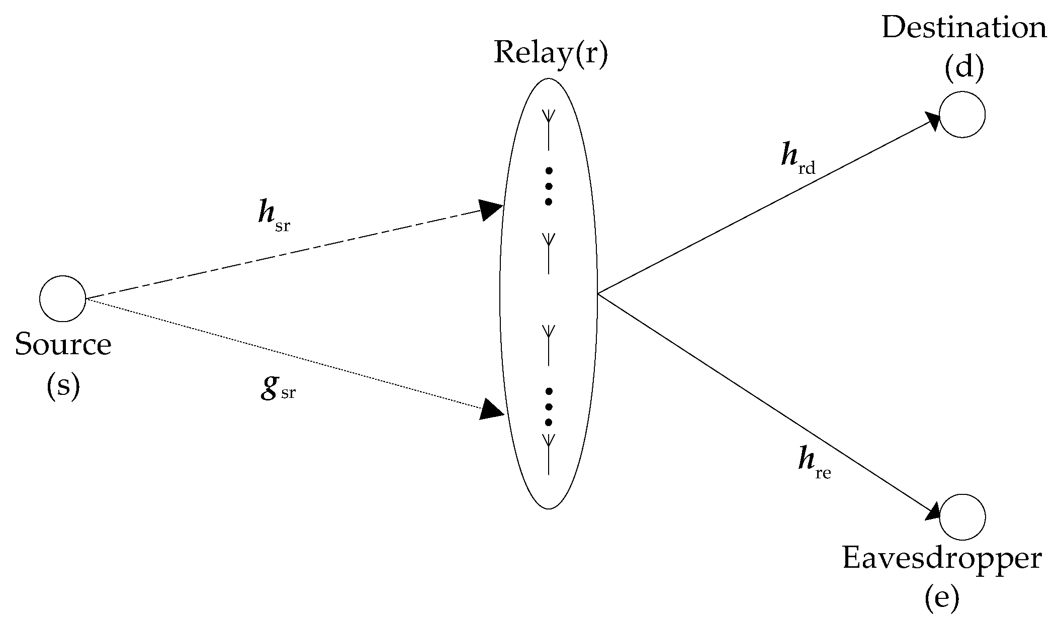
A source (s) transmits information to two receiving nodes, but the information transmitted to one node needs to be kept secret from the other node. Hence, for one receiver, the other receiver is an eavesdropper. Without loss of generality, in a timeslot, the node that receives information is called the destination (d), and the other node is called eavesdropper (e). Since obstacles are present between the source and the receivers, there is no direct link between the source and any receiving node, and, as a result, the information must be forwarded by a relay (r). The system model is shown in
Figure 1. The relay is equipped with
M antennas. Since the signal sent to both receivers needs to be forwarded by the relay, and the relay may ask them to feedback CSI, we assume that the relay can obtain all the CSIs. All channels are unrelated to each other, and they are quasi-static, memoryless, and undergo flat Rayleigh fading. In addition, the noise at any node is additive white complex Gaussian noise with zero-mean and variance
.
With the constraints of location and environment, in our model, the relay cannot be powered by power lines. Because the energy stored in relay’s battery is limited, the power used for information forwarding is very small, so the data rate will be very low. The rate system will be restricted by the rate of the second hop, in spite of the high achievable rate of the first hop. To alleviate the limit of power supply, we propose an “energy harvesting-AF” strategy. The process of transmission from the source to the destination is divided into two stages. In the first stage, the source sends information; one group of the relay’s antennas receives the confidential information, while the other group receives RF signals and converts it into energy. In the second stage, the relay amplifies and forwards signals with the energy both harvested in the first stage and stored in its battery. In this way, more power is focused on the antennas that are better for forwarding. Although the achievable rate of the first hop will decrease, the rate of the second hop will obviously increase, so that the rate of the system will be promoted.
is defined as the set of relay antennas and , wherein represents the amount of antennas in the set. The set is divided into two subsets of and , and satisfies , , and . The antennas in the subset are used to relay information, while the antennas in the subset are used to harvest energy. We denote the channel coefficient vector between the source and the antennas in the subset as , and the channel coefficient vector between the source and the antennas in the subset as . The channel coefficient vectors from the antennas in the subset to the destination and the eavesdropper are denoted by and , respectively: , , , .
In the first stage, the source transmits symbol
with unit power, i.e.,
, where
denotes expectation. The source has a transmit power constraint
. The received signal of the relay can be expressed as:
where
are the additive noises received by the antennas in the subset
. Meanwhile, the relay harvests energy through the antennas in the subset
. We assume that
is the power constraint of the relay when only the energy stored in its battery can be used. When
, all antennas of the relay are used to forward signals. In this case, the practical power constraint of the relay is
. If
, the received signal of the
-th
antenna in the subset
can be expressed as:
where
denotes the additive noise received by antenna
. Assume that the signal is converted to energy with the efficiency of
, and
. As the harvested energy is also used in AF, the total power of forwarding signals in the second stage will be:
In the second stage, the relay forwards information by the antennas in the subset
. The transmitted signal of the relay is denoted by
, where
is a diagonal matrix composed of a beamforming vector
, i.e.
.
can be rewritten as:
The transmission power of the relay should satisfy the constraint Equation (5) as follows:
The received signals at the destination and the eavesdropper are:
where the superscript T denotes matrix transpose,
and
, respectively, represent the noise at the destination and the eavesdropper. The SNRs (Signal to Noise Ratios) at the destination and the eavesdropper can be calculated as:
3. Optimization Analysis
In information-theoretical security, the secrecy rate is defined as
, where
and
are, respectively, the rates at the destination and the eavesdropper. In our model, they can be formulated as:
In the formulae, the coefficient 1/2 means the relay forwards data in half the time of a time slot. Thus, the secrecy rate is:
The beamforming vector
is constrained by Equation (10) as follows:
where
is an
identity matrix. The optimization problem can be formulated as:
As the channels are quasi-static, the channel coefficients over a period of time will be constant. The maximum Rs can be obtained by optimizing four optimization variables: , , , and . The first three variables determine the antenna grouping. If the antenna grouping has been determined, i.e., the variables , and are known, the original optimization problem can be simplified into the optimization of the beamforming vector . Therefore, the original optimization problem of formula (11) can be split into two parts. The first part is the optimization of under a certain , and , and the second is to determine the antenna grouping. An exhaustive antenna grouping scheme, which tries all the possible combinations of , , and and obtains corresponding and secrecy rate , can be used to get the optimal solution. This scheme has the optimal performance, but with a very high complexity. Therefore, we propose a low complexity antenna grouping scheme. and are determined according to an antenna choosing rule at a given , and then is calculated. secrecy rate will be obtained as increases from 1 to . The , , and that correspond to the maximum are the optimized antenna grouping and beamforming scheme we are looking for. The performance of this scheme is sub-optimal because we have not tried all the possible grouping of the antennas, but its computational complexity is significantly lower than that of the previous grouping scheme.
3.2. Antenna Grouping Scheme
As the number of relay antennas is limited, the optimal antenna grouping scheme can be obtained by trying all possible subsets . The number of the subset is when . The total number of subset is when varies from 1 to . A subset corresponds to a beamforming vector and secrecy rate . The , , and corresponding to the maximal are the solutions of the optimization problem. The computation amount of and is also . Although this antenna grouping scheme can obtain the optimal solution, its computation complexity is too high. Here, we give a low complexity antenna grouping scheme with the acceptable performance loss.
We find that the change of and will lead to the change of channel coefficients , , and in Equation (9). Thus, we design a rule to determine and in a given . Define as the channel coefficient between the source and the -th antenna of the relay, and , respectively, as the channel coefficients from the -th antenna of the relay to the destination and the eavesdropper, . and have a great impact on the secrecy transmission performance in the second stage. Obviously, in order to enhance security performance, we should choose the antenna that has a preferable channel performance to the destination but a poorer channel performance to eavesdropper to receive and forward information. Thus, we use as a metric to choose the AF antennas. Antenna with a lower value of is more suitable for the forwarding. On the other hand, the amount of the energy harvested in the first stage will determine the transmitting power in the second stage, which has significant impact on secrecy performance, and it is determined by . Therefore, in theory, we should give priority to the antenna with large to harvest energy and the antenna with small to forward information.
From the two aspects above, the antennas of the relay can be grouped according to the channel parameter . We sort the antennas according to the descending order of . The first antennas are the members of subset , and remaining antennas are the members of subset . As varies from 1 to , there are subsets , , and corresponding . The and antenna grouping corresponding to the maximum of secrecy rates will be the sub-optimal antenna grouping scheme.
Here, we compare the complexity between the optimal and the sub-optimal antenna grouping schemes. The former searches and computes times, and the latter computes only times. The sub-optimal antenna grouping scheme has evidently lower computational complexity.
4. Simulation Results
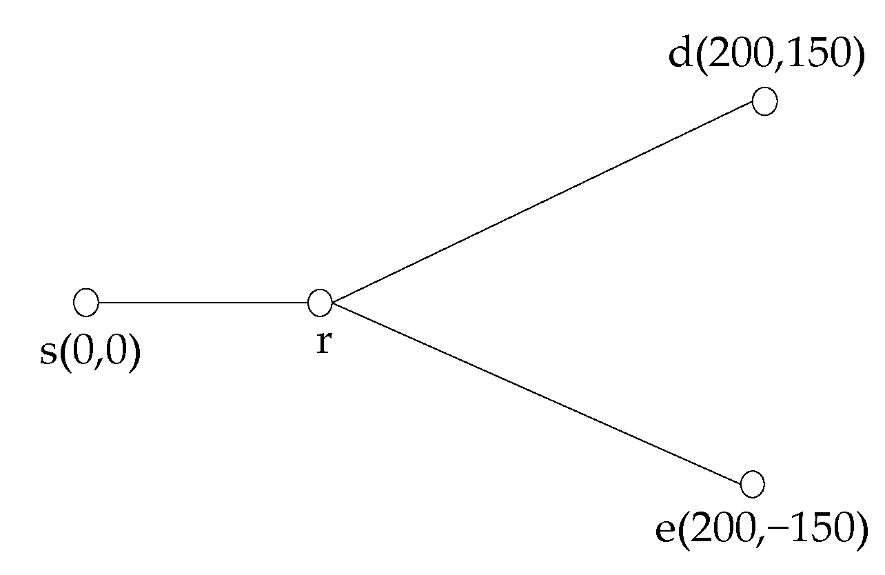
The performance of the proposed scheme is simulated in this section. The coordinates of the nodes are shown in
Figure 2. We set the source (s), the destination (d) and the eavesdropper (e), respectively, at
,
,
(Unit: m). For all channels, path loss and small-scale fading that obey Rayleigh distribution are considered, i.e.
. Where,
is the path loss exponent,
(unit: m) represents the distance between two nodes, and
is the path loss (amplitude). In addition,
is the zero-mean complex Gaussian variable with unit variance, and it represents the small-scale fading factor. We set the variance of noise at all nodes to
. In the process of energy harvesting, the received signal power is converted to DC power with the efficiency
[
19]. The results showed in this section are the average values of the data obtained in 5000 independent trials.
We compare our strategy with the traditional AF relay strategy, where the relay uses all antennas to forward information. Furthermore, the same beamforming as that in our strategy is used in the traditional AF strategy.
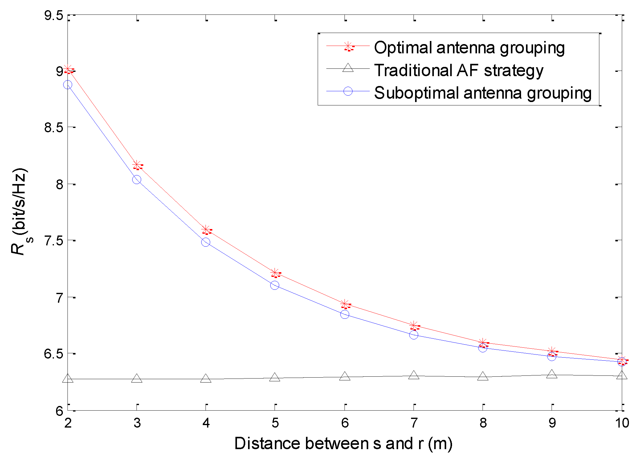
Figure 3 shows the relationship between the relay position and secrecy rate. We set
,
and
. The simulation results show that the security performance of the proposed “energy harvesting–AF” strategy is better than the traditional AF strategy. In the traditional AF strategy, the relay forwards information only with the battery energy, so the forwarding power will be very low. Although the relay uses all antennas to forward information, the secrecy rate is still limited. In the proposed “energy harvesting–AF” strategy, the relay can supplement energy through energy harvesting; therefore, it will have higher forwarding power. Because of the logarithmic relationship between the transmission rate and SNR, the increase of transmission power can bring significant improvement of the transmission rate in the low power region. On the other hand, with the increase of distance between the source and the relay, the path loss is also increasing, so the harvested energy is exponentially decreasing, and, consequently, the secrecy rate of the system decreases. Although the relay is closer to the destination, its influence is far less than that of the decrease of the relay forwarding power, so the secrecy rate of the system declines. It also can be seen from
Figure 3 that the secrecy rate of the optimal antenna grouping scheme is higher than that of the sub-optimal one, but the gap is not obvious. Therefore, the sub-optimal antenna grouping scheme significantly reduces the computational complexity at only the cost of acceptable performance loss.
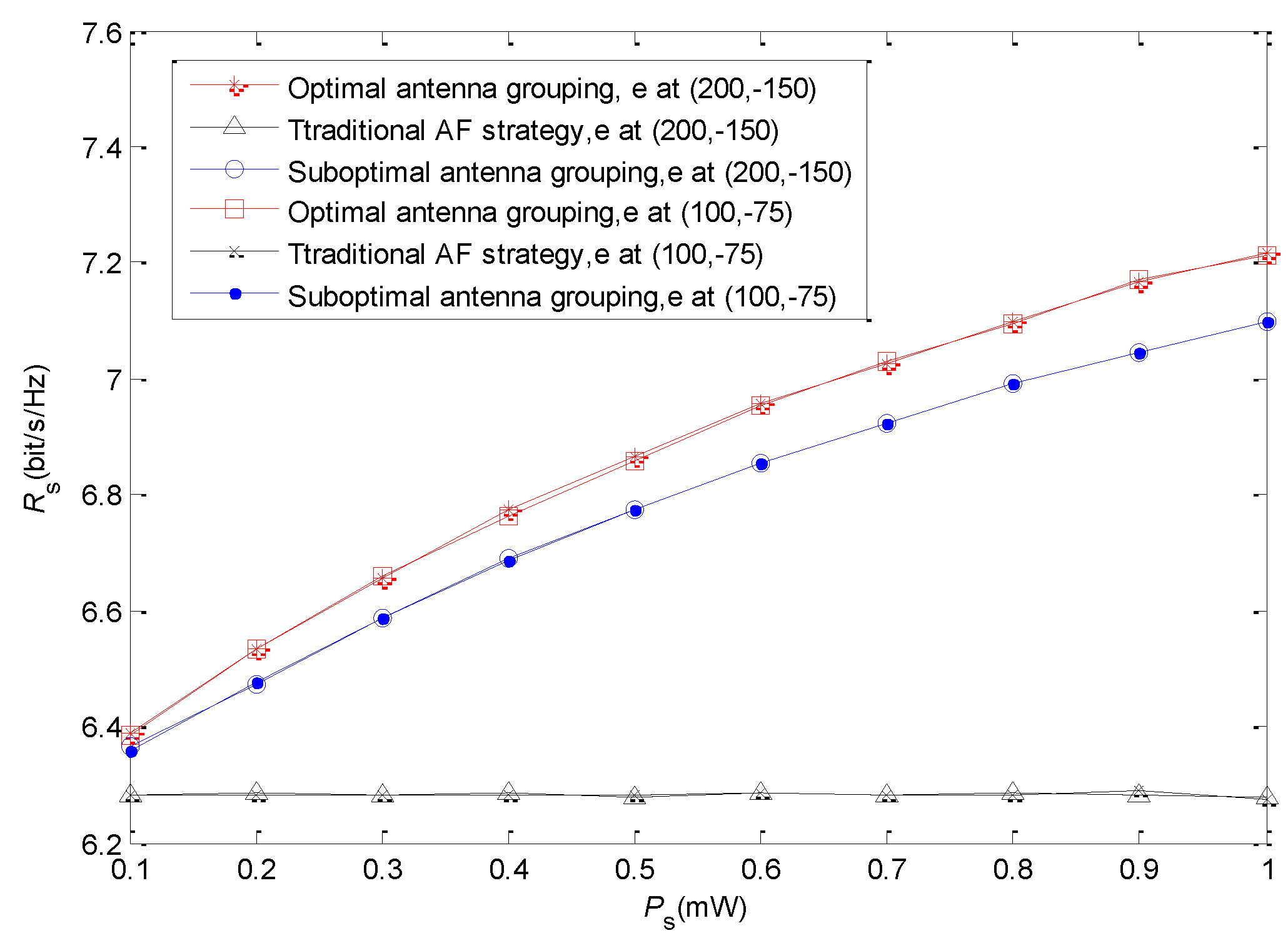
Figure 4 shows the secrecy rate with different source transmission power. We also set
and
, while the coordinate of the relay is fixed at
. The source transmission power
increases from 0.1 mW to 1 mW. We find that the secrecy rates of the proposed strategy with two antenna grouping schemes are both increasing when the source transmission power gets higher. This is because the increase of source transmission power on the one hand is beneficial to the improvement of the receiving SNR of the relay, and, on the other hand, can increase the harvested energy of the relay. However, in the traditional AF strategy, although the receiving SNR of the relay can also be improved by increasing source transmission power, the secrecy rate is not obviously improved due to the low forwarding power of the relay. In addition, it can also be found that the secrecy rate gap between the two antenna grouping schemes increases with the increase of source transmission power. The increase of the source transmission power leads to the increase of the receiving SNR and the harvested energy of the relay. The sub-optimal antenna grouping scheme prefers the antennas with better link quality to the source to harvest energy, and the effect of receiving signal SNR of the relay is not considered adequately. This will not have an obvious influence when source transmission power is low, but it will become serious when source transmission power is high. We also give the secrecy rate when the location of the eavesdropper is
, closer to the relay than the destination. As the eavesdropper only receives a signal in the second stage, where the secure beamforming is used, the secrecy rates are nearly the same.
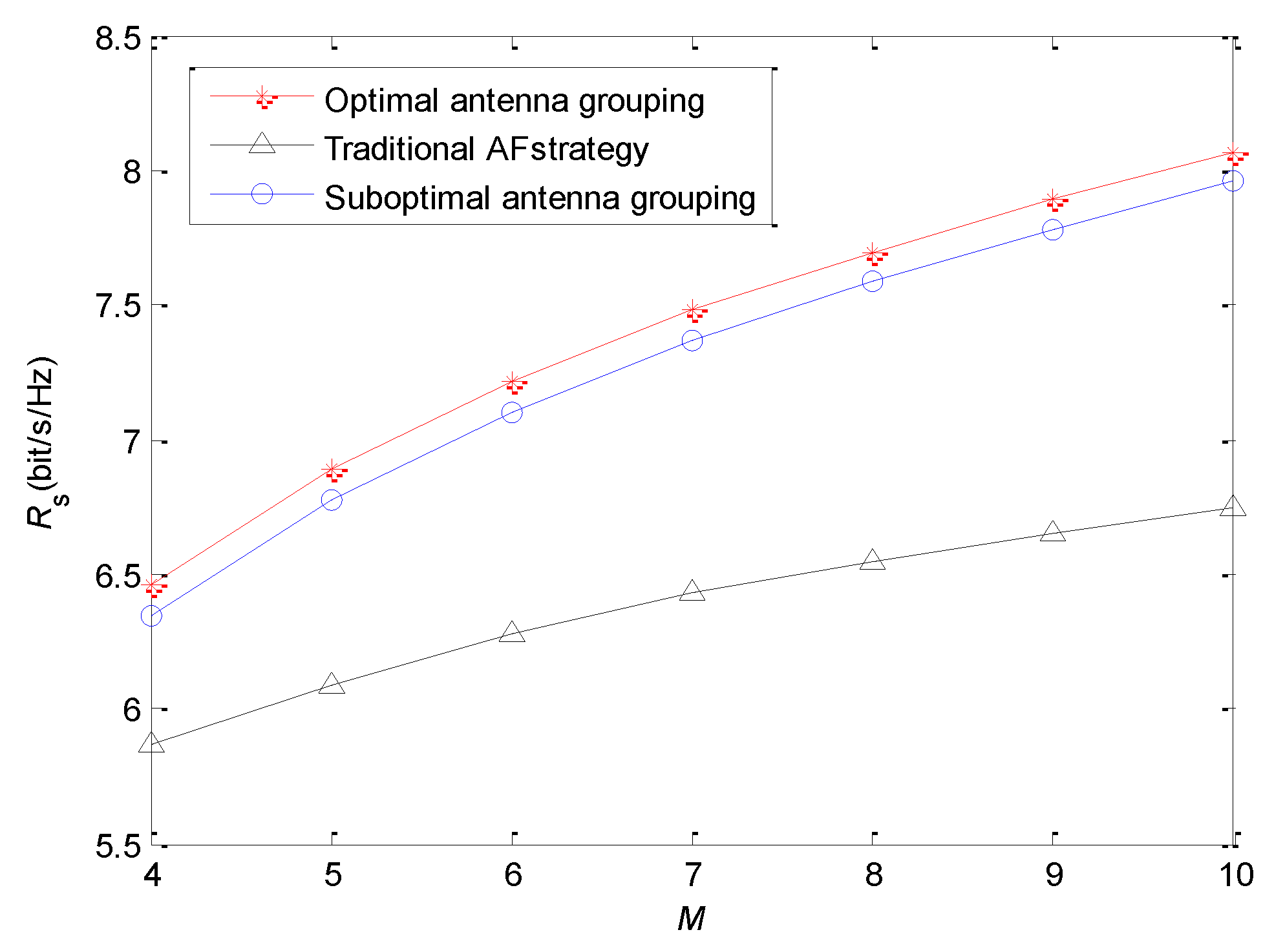
The relationship between antenna number of the relay and secrecy rate is shown in
Figure 5. We set the coordinate of the relay at
, and set
and
.
increases from four to 10. For the traditional AF strategy, the increase of
will enhance beamforming gain, so the achievable secrecy rate can be improved. However, in the proposed “energy harvesting–AF” strategy, the increase of
has two benefits. One is that more antennas can be selected into the subset
, which means that there are more antennas receiving and forwarding signals. In this case, the beamforming gain of the second stage will improve. The other is that more antennas can be assigned to the subset
. Thus, the forwarding power will increase because more energy is harvested by the relay. They are both conducive to enhancing the security performance of the system. Therefore, with the increase of
, the secrecy rate of “energy harvesting–AF” strategy increases significantly. In addition, the “energy harvesting-AF” strategy can use the antennas more flexibly, so its performance is higher than that of the traditional AF strategy.
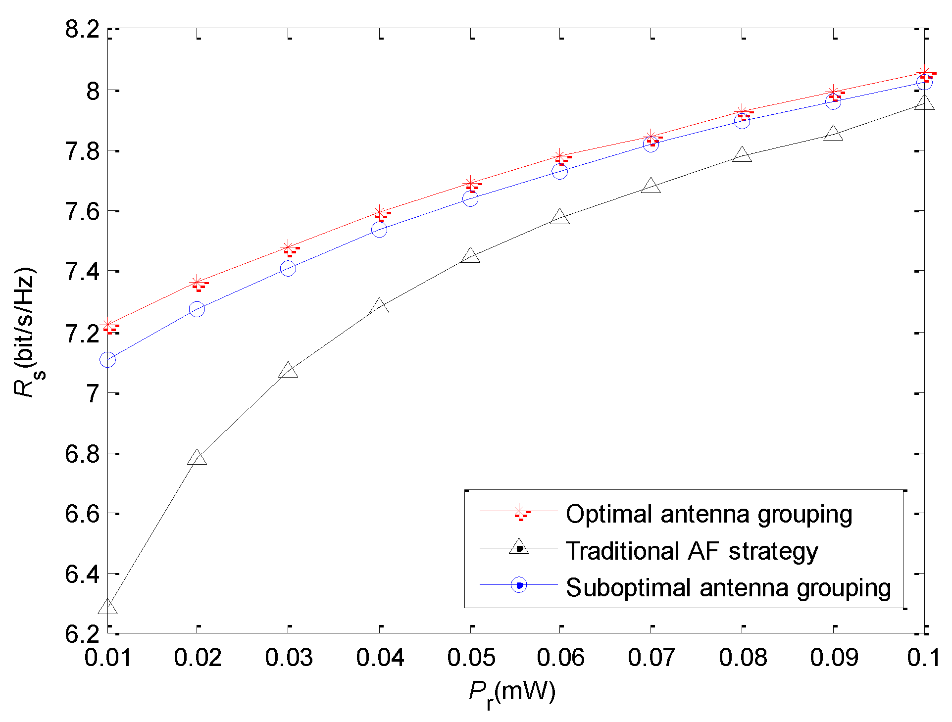
Figure 6 illustrates the relationship between
and secrecy rate. We set the coordinate of the relay at
, and set
and
.
increases from 0.01 mW to 0.1 mW. Obviously, the forwarding power of the relay affects directly the receiving SNR of the destination. Although the receiving SNR of the eavesdropper is also affected, its promotion is less than that at the destination due to the beamforming. Thus, the secrecy rate increases with the raise of
. From
Figure 6, we find that the gap of the secrecy rate between the “energy harvesting–AF” strategy and the traditional AF strategy is reduced when
increases. Due to the logarithmic relationship between transmission rate and SNR, the performance improvement induced by energy harvesting becomes less evident when
becomes higher.


