Article

Standard Compliant Hazard and Threat Analysis for the Automotive Domain

by
Kristian Beckers
1,*,
Jürgen Dürrwang
2,* and
Dominik Holling
1,*
1
Software Engineering, Technical University Munich (TUM), Boltzmannstr. 3, Garching bei Muenchen 85748, Germany
2
Institute of Energy Efficient Mobility, University of Applied Sciences, Moltkestrasse 30, Karlsruhe 76133, Germany
*
Authors to whom correspondence should be addressed.
Information 2016, 7(3), 36; https://doi.org/10.3390/info7030036
Submission received: 14 February 2016 / Revised: 5 May 2016 / Accepted: 14 June 2016 / Published: 23 June 2016
(This article belongs to the Special Issue Evaluating the Security of Complex Systems)

Abstract

:
The automotive industry has successfully collaborated to release the ISO 26262 standard for developing safe software for cars. The standard describes in detail how to conduct hazard analysis and risk assessments to determine the necessary safety measures for each feature. However, the standard does not concern threat analysis for malicious attackers or how to select appropriate security countermeasures. We propose the application of ISO 27001 for this purpose and show how it can be applied together with ISO 26262. We show how ISO 26262 documentation can be re-used and enhanced to satisfy the analysis and documentation demands of the ISO 27001 standard. We illustrate our approach based on an electronic steering column lock system.

Graphical Abstract

KWPKeyword Protocol 2000 UDSUnified Diagnostic Services OBDOn-board diagnostics CANController Area Network LINLocal Interconnect Network MOSTMedia Oriented Systems Transport ECUElectronic Control Unit TPMSTire Pressure Monitoring System RPMRevolutions Per Minute VANETVehicular Ad Hoc Network TPTransport Protocol IPInternet Protocol OSIOpen Systems Interconnection ABSAntilock Break System ESCElectronic Stability Control OEMOriginal Equipment Manufacturer ASILAutomotive Safety Integrity Level AUTOSARAUTomotive Open System ARchitecture CPUCentral Processing Unit USBUniversal Serial Bus HMACKeyed-Hash Message Authentication Code TMCTraffic Message Channel WMAWindows Media Audio ASDLAutomotive Security Development Lifecycle FMEAFailure Mode and Effects Analysis FTAFault Tree Analysis UMLUnified Modeling Language ISOInternational Organization for Standardisation CIAConfidentiality, Integrity, and Availability HAZOPHazard and Operability Study

1. Introduction

Since the invention of the automobile, safety is an essential concern in its success story. Implementing safety in vehicles and protecting the passengers inside as well as road users from physical harm lead to a drastic reduction of traffic fatalities [1]. Revolutionary safety measures such as seat belts, anti-lock braking systems and airbags are only a few to contribute to this protection. All of these measures aim mitigating the risks of human error or technical failure. In 2011, the automotive industry successfully collaborated on the International Organization for Standardisation (ISO) 26262 [2] standard for the safety of electronic systems in passenger cars produced in series. These electronic systems are software-intensive driving-comfort systems including drive-by-wire, adaptive cruise control and lane departure warning systems among others.
Without the use of (distributed) software solutions, the comfort and fuel economy of today’s cars cannot be achieved. Particularly, state-of-the-art safety functionality like collision prediction is impossible without intelligent software solutions. However, while passenger vehicles have previously contained software systems, the connectivity of vehicles is increasing and security increasingly becomes a concern. Particularly through the use of internet and Car2X services, scalable remote attacks by skilled attackers seem plausible. The biggest fear is the interference with safety in such an attack. Most critical would be the deactivation of the breaks [3], steering [4] or other vital systems endangering a vehicle’s roadworthiness leading to fatal consequences. Note that, previous attacks on safety-critical systems required the attacker to have physical access to the vehicle at least once before being able to execute a remote attack on a safety-critical system. Recent attacks [3] have shown to not require physical access.
To combat these threats, measures to encrypt bus communication and bring trusted computing to all electronic control units (ECUs) running software solutions are needed [5]. These solutions do not require changes to the deployed functional software or its development process, but to the underlying AUTomotive Open System ARchitecture (AUTOSAR)-compliant basic software. They are able to mitigate many security risks and raise the bar for attackers. However, these solutions face the same key management problems present in IT systems [5] and increase the cost of each ECU by an order of magnitude. Since manufacturing cars is driven utmost by the unit price, the deployment cost of trusted computing hardware may be very costly. In addition, selling a vehicle security package against remote attackers may be hard to justify to the customer as customers expect inherent security.
Instead of using a one size fits all solution hardware solution to address the security, we propose a comprehensive and holistic approach for the security of safety-critical systems in vehicles developed using the ISO 26262. We aim to combine the ISO 26262 with a security standard of worldwide significant impact. The ISO 27001 standard [6] and the Common Criteria [7] are two commonly accepted security standards. In 2014, the ISO [8] registered 23 972 ISO 27001 certifications, which represents an increase of 7 % as compared to 2013. The ISO also registered 275 Common Criteria certifications in 2015, a 15 % increase compared to 2014 [9]. These numbers cover certifications worldwide and show the relevance of security standards. Thus, our approach follows the state-of-the-art security standard ISO 27001 to analyze threats, perform a security risk analysis and reason about controls to specifically address threats. This research is based on previous work regarding ISO 26262 [10] and ISO 27001 [11]. By re-using existing artefacts required by the safety lifecycle in the security lifecycle, it is compliant to both ISO standards and enables the security certification of these safety-critical systems. Nevertheless, we do not enforce the certification option within our method. It can also be applied without the aim of certifications and just the aim to consider security in the safety engineering lifecycle. Our approach provides cost-effective and appropriate measures for security requirements based on existing knowledge. It provides an overview that is able to identify if a security problem is addressed multiple times or with too excessive and thus costly measures. It is able to provide specific measures for the automotive domain such as plausibility checks or hardening of gateways between different buses for example, which has been shown to prevent attacks in the past [12].
We contribute a structured, standard compliant approach to support security reasoning in the automotive domain. The approach is based on our previous research, which requires the overhead of a dedicated security process possibly performable by (safety) engineers. The systematic and structured approach we present here helps experts in safety to consider security, as well. There is no need to change every functional software, every development process or every underlying basic software. Specific security measures similar to the ASIL levels (see Section 1.2) in safety will have to be taken to specific parts of the system based on particular automotive attacker models. Analogous to ISO 262626, the security goals and measures derived from our approach can later be refined into a conceptual and technical security concept as well as hardware and software security requirements. The cost of this overhead is analogue to the overhead required by using ECUs lacking a floating point module or floating point modules in the automotive domain. While this make the development of software more complicated, it reduces the cost of hardware and evidently enables unit price savings. Particularly our proposed automotive control measures such as plausibility check or gateway hardening are well-known and implementable with a low effort.
Obviously, automotive security also encompasses further systems other than safety-critical systems including privacy-sensitive (e.g., extraction of location data from the telematics ECU) or infotainment systems (e.g., setting audio volume to maximum in the entertainment ECU). However, we see the mitigation of security risks for safety-critical systems as a top priority and broaden the safety scope of ISO 26262 to form the security scope of ISO 27001 accordingly. Thus, our aim in terms of the Confidentiality, Integrity, and Availability (CIA) triad is to ensure data integrity of the signals exchanged while availability is already ensured by the safety considerations and confidentiality is disregarded. Our approach is an instantiation of the secure by design paradigm for safety-critical systems and derives high level security goals to be refined. This refinement will have to be based on security best practices and existing knowledge in the security engineering domain.
Problem: Security is a new concern in the area of safety-critical automotive systems developed according to ISO 26262. Proposed security measures for automotive security are a one size fits all hardware-based solution. These solutions miss the security overview and are costly and may not be required in all cases.
Solution: We create a comprehensive and holistic approach compliant to ISO 26262 for safety and ISO 27001 for security for safety-critical automotive software systems. It re-uses existing safety lifecycle artifacts as basis for the security lifecycle with little overhead by the derivation of specific measures for automotive security. We set up an ISO 27001 compliant information security management system (ISMS), which does not only find reasonable security countermeasures for identified threats, but also enforces processes that check over time if attacker assumptions still hold and enforce periodic security checks of the countermeasures during runtime. That being said, in this publication we focus on how to establish the ISMS within the ISO 26262 approach. An advantage of our approach is that the security part is an appendix to the ISO 26262 process and only gathers inputs from it. This way the safety process can be left unchanged and carry out isolated from the security part. A strong intertwining between these two processes might cause severe efforts when the ISO 26262 standard changes. In our way we only need to check that the output of the process is still the needed one, even though the underlying process might have changed in the standard.
Contribution: We contribute a structured, standard compliant approach possibly performable by (safety) engineers yielding specific threat-based measures to be taken. We included automotive attacker models specifically tailored to the bus systems commonly used in the automotive domain and automotive security controls well-known and implementable with low effort. We limit our scope of automotive security to the scope of ISO 26262 safety-critical systems and the data integrity of the signals exchanged.

1.1. Requirements Analysis

We use a requirements engineering method inspired by Jackson [13]. Requirements can only be guaranteed for a certain context. Therefore, it is important to describe the environment, because we build a system to improve something in the world. The environment in which the system to be built (called machine) will operate is represented by a context diagram.
We use the Unified Modeling Language (UML) [14] notation with stereotypes defined in the UML profile UML4PF [15] to create a context diagram. Stereotypes give a specific meaning to the elements of a UML diagram they are attached to, and they are represented by labels surrounded by double angle brackets.
A class with the stereotype ≪machine≫ represents the thing to be developed, i.e., the machine. The other classes with a ≪domain≫ stereotype represent elements in the application environment that already exist.
Domains are connected by interfaces consisting of shared phenomena. Shared phenomena may be events, operation calls, messages, and the like. They are observable by at least two domains, but controlled by only one domain, as indicated by an exclamation mark. These interfaces are represented as associations with the stereotype ≪connection≫, and the name of the associations contain the phenomena and the domains controlling the phenomena.
When we state a requirement, we want to change something in the world with the machine to be developed. Therefore, each requirement constrains at least one domain. This is expressed by a dependency from the requirement to a domain with the stereotype ≪constrains≫. Such a constrained domain is the core of any problem description, because it has to be controlled according to the requirements. Hence, a constrained domain triggers the need for developing a new system (the machine), which provides the desired control. A requirement may refer to several domains in the environment of the machine. This is expressed by a dependency from the requirement to a domain with the stereotype ≪refersTo≫. The referred domains are also given in the requirement’s description.

1.2. ISO 26262

ISO 26262 is a risk-based functional safety standard intended to be applied to safety-related systems that include one or more E/E systems and that are installed in series productions of passenger cars with a max gross weight up to 3500 kg. It addresses possible hazards caused by malfunctions of E/E safety-related systems, including the interaction of these systems.
ISO 26262 was derived from the generic functional safety standard ISO/IEC 61508 [16] and was published on 11 November 2011. It is aligned with the automotive safety lifecycle including specification, design, implementation, integration, verification, validation, configuration, production, operation, service, decommissioning, and management. ISO 26262 provides an automotive-specific risk-based approach for determining risk classes that describe the necessary risk reduction for achieving an acceptable residual risk, called automotive safety integrity level (ASIL).
The possible ASILs are QM, ASIL A, ASIL B, ASIL C, and ASIL D. The ASIL requiring the highest risk reduction is called ASIL D. For functions with ASIL A, ASIL B, or ASIL C, fewer requirements on the development processes, safety mechanisms, and evidences are given in ISO 26262. In case of a QM rating, the normal quality measures applied in the automotive industry are sufficient.

1.3. The ISO 27000 Series of Standards

The ISO 27000 series of standards addresses information security matters and the subsequent Information Security Management System (ISMS). This is a system independent of vendors, technologies or the size/type of organization that is part of the management system of an organization [17].
The central standard in the series is the ISO 27001, which defines the requirements for an ISMS. A certification of an implementation of the ISO 27001 process is possible. All the other standards of the series are specifications of this standard and describe parts or usage scenarios of the ISMS in detail [18].
The ISO 27000 standard [18] divides the standards of the ISO 27000 series of standards into four categories. The ISO 27000 standard itself defines the terminology of the series, the ISO 27001 states the general requirements for an ISMS. General guidelines specify parts of the ISMS e.g., the ISO 27005 specifies risk management. Sector-specific guidelines describe how an ISMS is to be implemented in a specific kind of organization, e.g., ISO 27011 concerns telecommunication organizations.
The ISO 27007 describes the auditing and certification of the ISO 27001 standard, while the ISO 27006 lists the certification body requirements. Organizations can get accreditation for certifying ISO 27001 realizations.
The remaining standards of the series describe a specific topic in relation to the ISMS. For instance, ISO 27010 describes how to combine different ISMS within one company, ISO 27031 describes business continuity management. However, even though numerous standards in the ISO 27000 series exist, that specify parts of the ISO 27001, it is not mandatory to use these specifications. The standard also allows to use different specifications, as long as they fulfill the requirements of the ISO 27001 [19]. Hence, we focus in our work on the ISO 27001 standard.

1.4. The ISO 27001 Standard
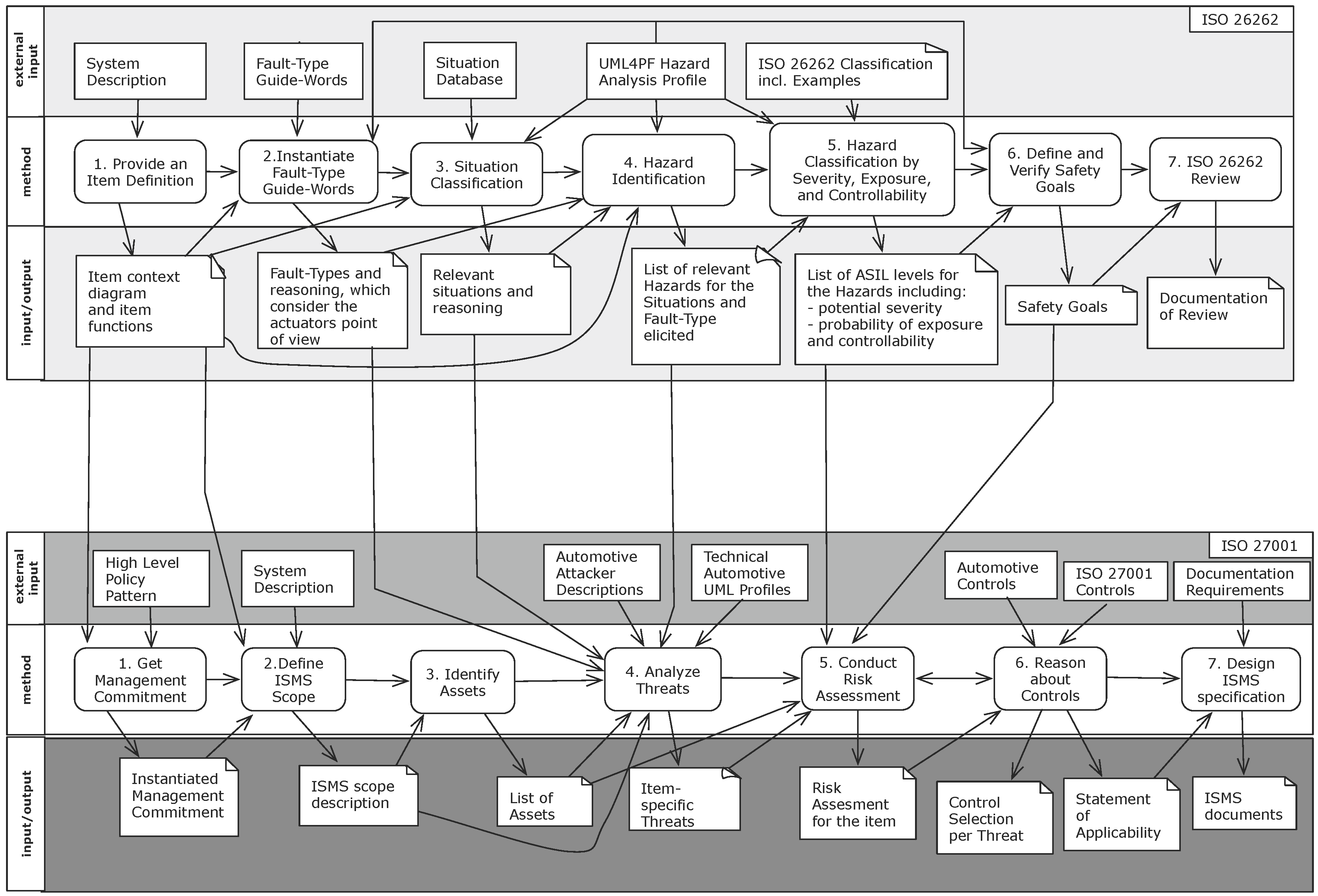
The ISO 27001 defines the requirements for establishing and maintaining an ISMS [6]. In particular, the standard describes the process of creating a model of the entire business risks of a given organization and specific requirements for the implementation of security controls. The ISO 27001 standard is structured according to a process that describes how to establish an ISMS, how to operate the ISMS and how an ISMS is monitored and reviewed, as well as maintained and improved. Initially, the scope and boundaries of the ISMS, its interested parties, environment, and all the technology involved are defined. Afterwards, ISMS policies, threat identification, risk assessments, evaluations, and controls are defined. Controls in the ISO 27001 are measures to modify risk.
Changes in the organization or technology also have to comply with the documented ISMS requirements. Furthermore, the standard demands periodic audits towards the effectiveness of an ISMS. These audits are also conducted using documented ISMS requirements. In addition, the ISO 27001 standard demands that management decisions, providing support for establishing and maintaining an ISMS, are documented as well. This support has to be documented via management decisions. This has to be proven as part of a detailed documentation of how each decision was reached and how many resources are committed to implement this decision.

2. Methodology

2.1. Hazard Analysis and Risk Management Compliant to ISO 26262

We propose a method for creating a hazard analysis and risk assessment according to ISO 26262. The aim of the analysis is to identify and classify the potential hazards of the item and to formulate safety goals related to the prevention or mitigation of these hazards in order to achieve an acceptable residual risk. The method consists of the following steps, depicted in Figure 1.

2.1.1. Safety-Step 1: Provide an Item Definition

ISO 26262 demands a definition of the item, its basic functionality, and its environment. We use the UML4PF profile extension for ISO 26262 to represent this description. The initial description of the item is provided in a context diagram that presents the item and the domains surrounding it, e.g., the driver.
The functions of the item are defined by requirements referring to or constraining domains in its environment (see Section 1.1). Instead of using the stereotype ≪machine≫, for the ISO 26262 item definition we use the stereotype ≪item≫ to define the domain to be developed.
It is also important to ensure that this step is performed on the right level of detail. It should be avoided to have a too detailed level with too many functions/sub-functions in order to make the hazard analysis assessable. As a rule of thumb the abstraction should reflect all relevant components and what information is exchanged on an abstract level, but not the technical specification of these data flows. For example, it is enough to know that a car light should be switched on with a message, the details of the encoding of the message is not relevant at this level of abstraction.

2.1.2. Safety-Step 2: Instantiate Fault-Type Guide-Words

We propose a set of so-called fault-type guide-words inspired by the Hazard and Operability Study (HAZOP) standard [20]. The guide-words help the developer to consider all relevant faults. Typical guide words are no, unintended, early, late, more, less, inverted and intermittent. Each guide-word has to be instantiated for the functions specified in the item definition in the previous step. In the context of a certain function, not all fault-types have to be considered. For example the fault-type “more” is not relevant for a function with a boolean output. For many time-critical functions, a fault-type “late” leads to the same hazard as the fault-type “no”. Usually, it is helpful to start the fault-type consideration from the actuator’s point of view and not from the sensor’s, because the task of the fault-type consideration is not a verification of an existing design. This will be done with appropriate safety analyses, e.g., Failure Mode and Effects Analysis (FMEA) [21] and Fault Tree Analysis (FTA) (Section 7.9, [22]), which take place after the ISO 26262 hazard analysis. For all combinations of function and fault, we describe how the system behaves in presence of the malfunction.
We support this step with a UML profile that can be used to express the different artefacts. Figure 2 shows the part of the profile that is used to express the faults of an actuator constrained by a functional requirement. A class with the stereotype is used to describe the faults. Each fault may be in one of the fault-types no, unintended, early, late, more, less, inverted and intermittent. For each requirement, all fault-types are checked if they have to be considered, are not possible, or are covered by other faults. A dependency with the stereotype is used to show the relation between requirements and faults. Additionally, fault constraints can be described. For each considered fault, we describe the effect on the system level and not on component or vehicle level. On the system level, the elements of the item are visible, e.g., actuators. In vehicle level descriptions, only phenomena that can be observed or controlled by the driver or other persons are used. The component level contains descriptions of internal interfaces, e.g., Controller Area Network (CAN) [23] messages. We consider only faults at the system level at this step, because considering all types of fault at once would raise the complexity of this step significantly. We assume that the lower level faults are detected by later refinement steps. For faults rated not to be considered, either a description why it is not relevant or a reference to at least one other fault using the attribute “covered by” has to be specified.

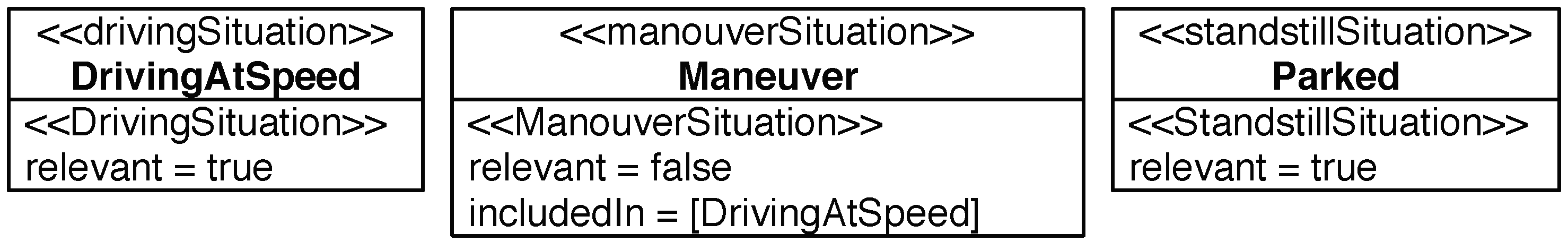
2.1.3. Safety-Step 3: Situation Classification

From project-experience, examples in the ISO 26262, national and international working groups, a hierarchically organized list of situations is created. Using this list, we rate if a situation is relevant for the described item with its requirements or not. If a more abstract situation is rated, it is not necessary to rate the special situations. If a situation is rated as not being relevant, either a reference to another situation that includes this situation is given, or a rationale that explains why the situation is not relevant (e.g., a maintenance device is only attached when the vehicle is parking and other situations are therefore not relevant) is provided. The hierarchically organized list of situations is updated if new aspects are identified in projects in order to reduce the risk of forgetting hazardous situations.
In the UML profile, a number of situations are defined as stereotypes. Situations are e.g., ≪standstillSituation≫, ≪maneuverSituation≫, and ≪drivingSituation≫. Special standstill situations are ≪standstillEngineOffSituation≫ (e.g., in parking lot) and ≪standstillEngineOnSituation≫. Special maneuver situations are, e.g., ≪parkingManeuverSituation≫ and ≪drivingBackwardSituation≫. Special driving situations are on the one hand driving activities like ≪brakingSituation≫, ≪accelerationSituation≫, ≪steeringSituation≫, and ≪rollingSituation≫, and on the other hand driving areas like ≪citySituation≫, ≪countryRoadSituation≫, and ≪highwaySituation≫. For the sake of brevity, we do not report all existing situations.

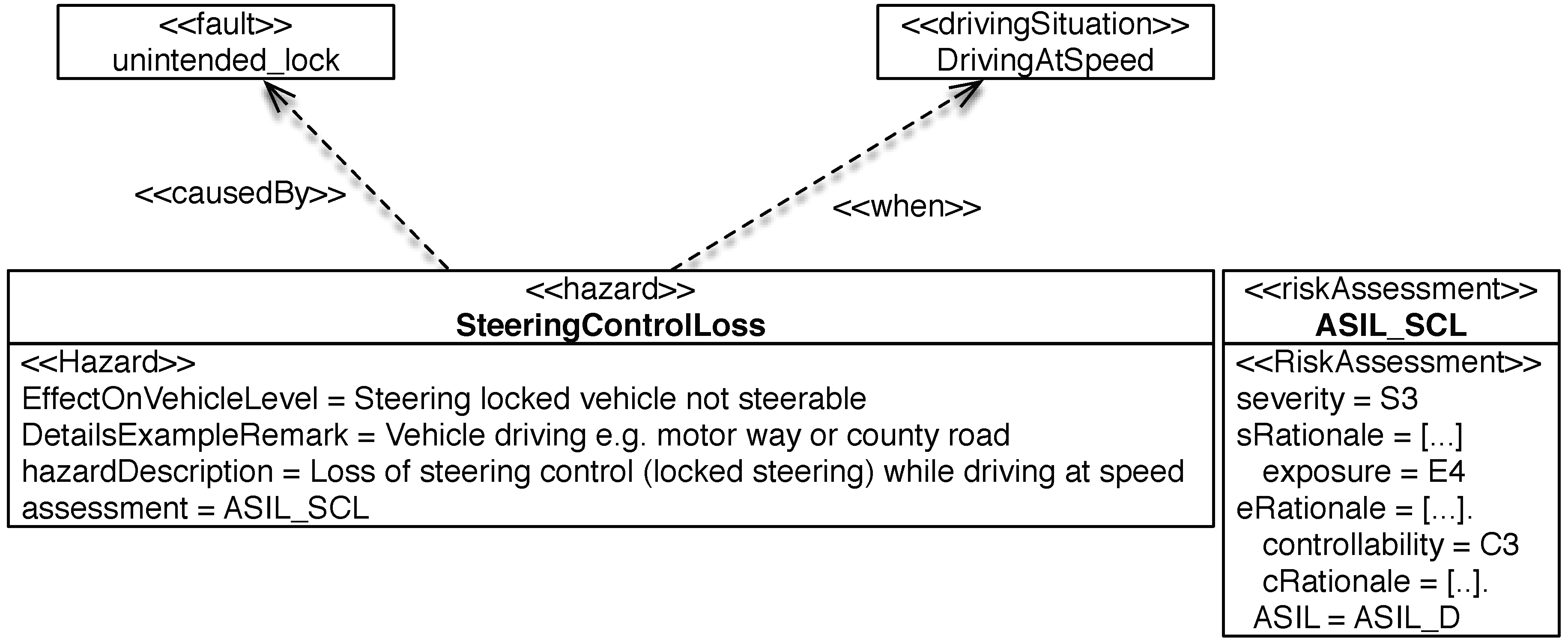
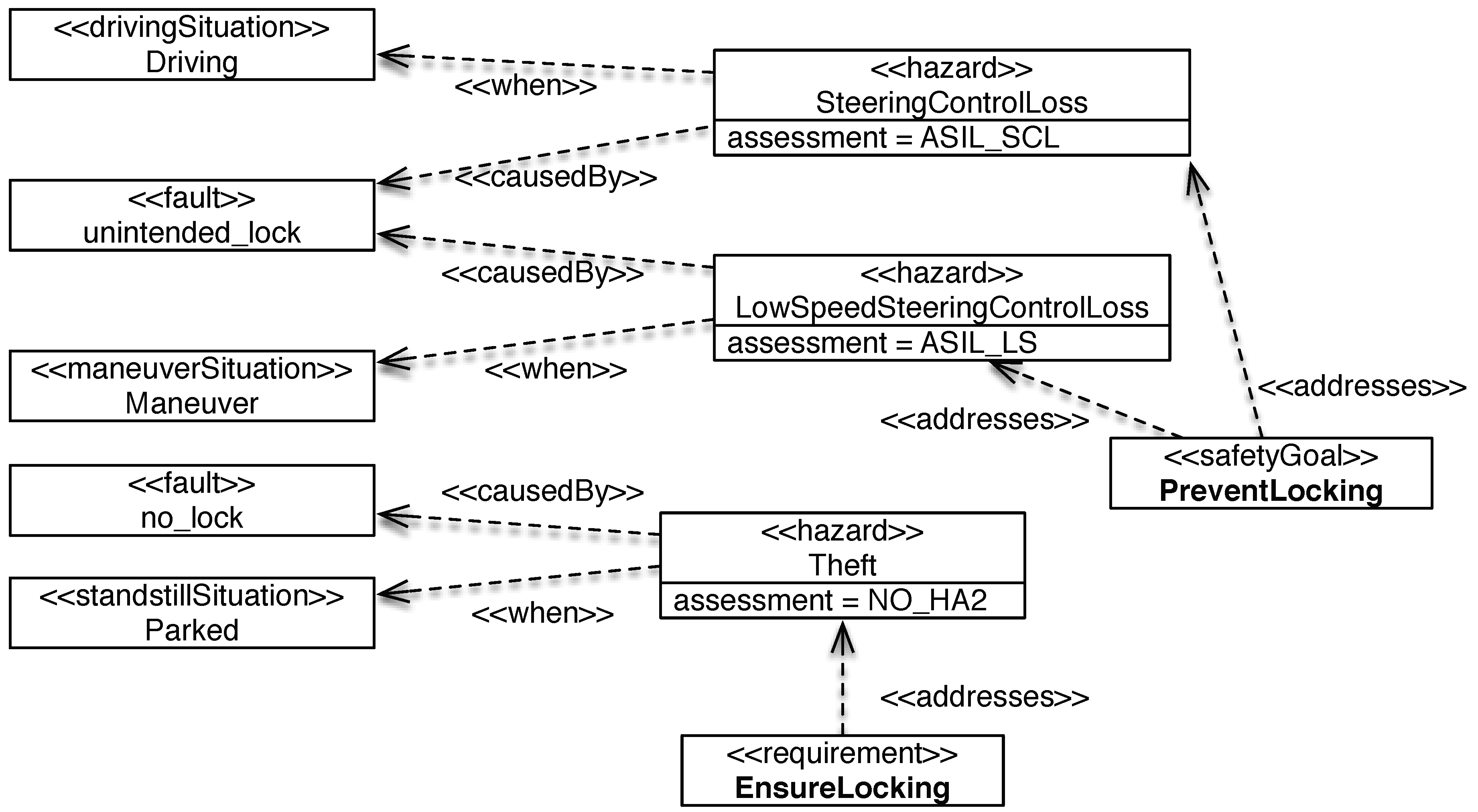
2.1.4. Safety-Step 4: Hazard Identification

For each fault/function combination, all situations that could lead to a potential hazard are identified in the list of situations being relevant. We describe the effect on the vehicle level, i.e., what behaviour could occur in case of a potential item malfunction. Based on the effect on the vehicle level, we describe the hazards and possible consequences. Hazards are defined in terms of the conditions or events that can be observed at the vehicle level (e.g., by the driver). A verbal description of consequences without ranking is given. In this step, also assumptions (e.g., on driver actions to maintain controllability) should be considered. Due to the complexity of documenting assumptions, we do not discuss assumptions in this paper.
A hazard is ≪causedBy≫ a set of faults and refers to situations ≪when≫ it can occur. This is expressed by stereotyped dependencies. It is important that each relevant situation is referenced by at least one hazard, and each of the faults of a domain that has to be considered is referenced by at least one hazard. Additionally, each Hazard has at least one ≪when≫-dependency and at least one ≪causedBy≫-dependency.
To describe the hazard, we use the stereotype ≪hazard≫ as depicted in Figure 2 and start with the description of the effect on vehicle level. We may give details, examples, or remarks, and provide a description of the hazard that includes the situations and the fault effect. The hazard refers to the risk assessment to be performed as described in the next paragraph.

2.1.5. Safety-Step 5: Hazard Classification by Severity, Exposure, and Controllability

The objective of the hazard classification is to assess the level of risk reduction required for the hazards. To classify the hazard, the following steps need to be performed according ISO 26262:
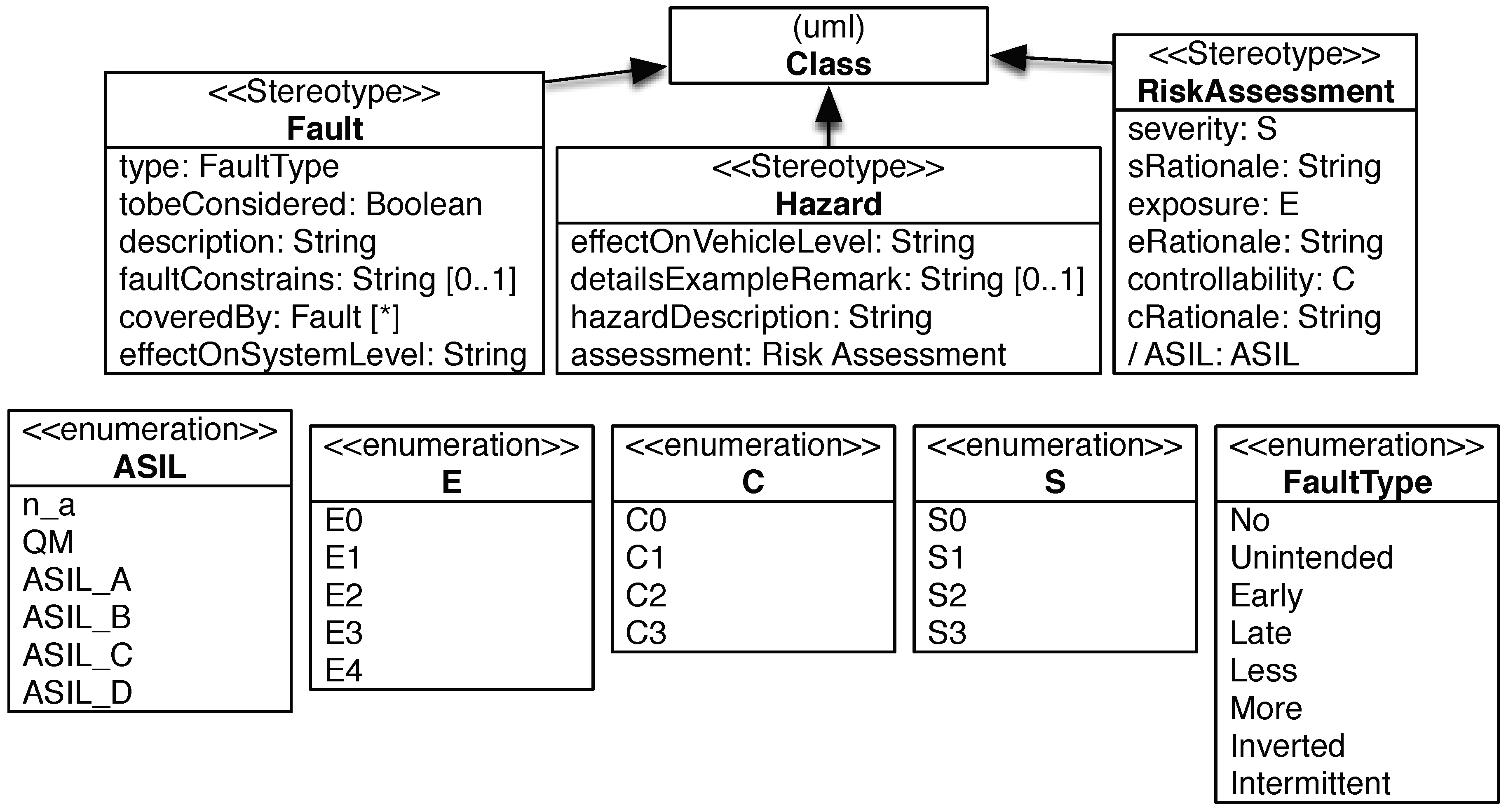
  • Estimate the potential severity and provide a rationale. ISO 26262 classifies the potential severity with the classes S0 (no injuries), S1 (light and moderate injuries), S2 (severe and life-threatening injuries, survival probable), and S3 (life-threatening injuries, fatal injuries).
  • Estimate the probability of exposure and provide a rationale. ISO 26262 classifies the exposure with the classes E0 (incredible, e.g., earthquake), E1 (very low probability, e.g., vehicle being towed), E2 (low probability, e.g., snow and ice on road), E3 (medium probability, e.g., heavy traffic with stop and go), E4 (high probability, e.g., highway).
  • Estimate the controllability and provide a rationale. ISO 26262 classifies the controllability with the classes C0 (controllable in general, e.g., maintain intended driving path in case of unexpected radio volume increase), C1 (simply controllable, e.g., brake to slow down/stop the vehicle in case of blocked steering column when starting the vehicle), C2 (normally controllable, e.g., maintain intended driving path in case of failure of ABS during emergency braking, C3 (difficult to control or uncontrollable, e.g., stay in lane in case of failure of ABS when braking on low friction road surface while executing a turn).
The description of and examples for the classes are taken from the standard [2] (Part 3, Appendix B). The risk assessment is documented in a class with the stereotype ≪RiskAssessment≫ as depicted in Figure 2. This stereotype has the attributes S, E, and C, each of them typed with enumerations representing the classes. Additionally, it has the attributes sRationale, eRationale, and cRationale of type String that are used to provide a rationale for the selected class. For a severity below S3, an exposure below E4, and a controllability below C3, a rationale has to be provided. The same rationale cannot lead to a different rating in other assessments. For example, the controllability rationale “no lateral control by steering is possible” cannot lead to C3 in one assessment and to C2 in another assessment.
Based on these estimations, the ASIL is determined automatically according to the corresponding ISO 26262 table. For example, a rating of S3, E4, and C3 leads to ASIL D. If one of the parameters is reduced to the lower class, ASIL C is derived. If the parameters are reduced more, ASIL B, ASIL A or QM is derived. In case of S0, E0, or C0, no ASIL is assigned and n_a is inserted into the rating attribute ASIL. Note that n_a is not part of the ISO 26262 standard, but our addition in order to have an identifier for the case that no ASIL rating is needed.

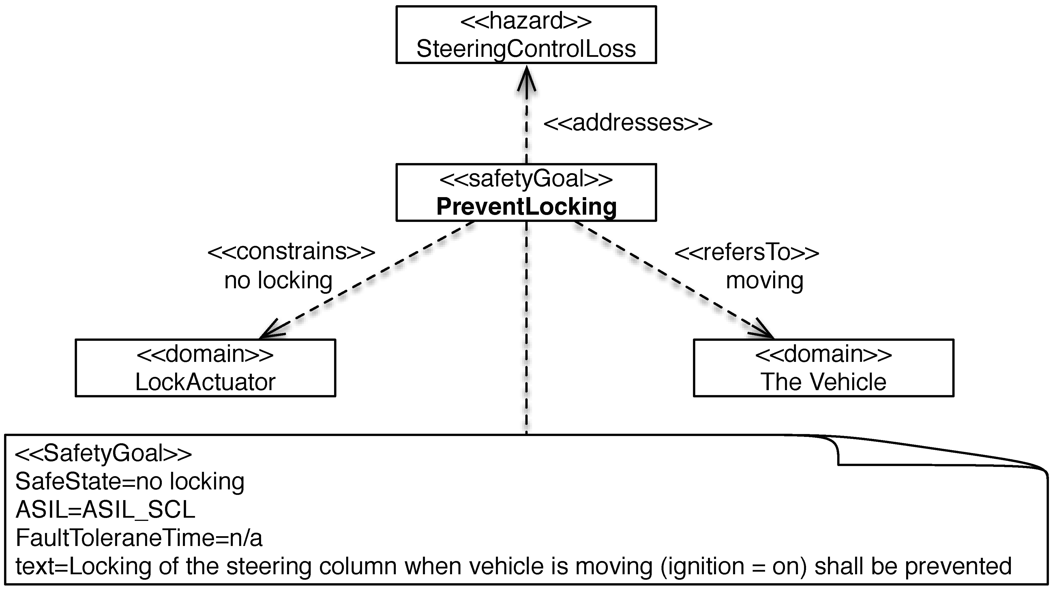
2.1.6. Safety-Step 6: Define and Verify Safety Goals

Safety requirements are special requirements with the attributes ASIL, safe state, and fault tolerance time (see Figure 3). The ASIL is a measure of necessary risk reduction. The safe state is a state that shall be entered to avoid a hazard. The fault tolerance time is the time an actuator state can be unsafe before the situation becomes hazardous, e.g., an undue brake intervention may have a fault tolerance time of 100 ms in certain situations. Safety requirements are defined on different levels. A safety goal is a top-level safety requirement based on the hazards identified in this analysis. Functional safety requirements are derived from the safety goals. Technical safety requirements are derived from the functional safety requirements and specified for all components of the item considering the concrete architecture.
Safety goals have to be clear and precise, do not contain technical details, but have to be implementable by technical means (e.g., avoid referring to non-measurable data). Like functional requirements, safety goals refer to domains and constrain at least one domain.
ISO 26262 requires that at least one safety goal is assigned to each hazard rated as ASIL A, B, C or D. It is not necessary to define safety goals for hazards rated as “QM” or “no assignment”, but hazards rated with QM shall be addressed by at least one requirement. Hazards with “no assignment” are documented and the safety engineers can address them with requirements, but do not have to. In reviews these are checked with particular care to avoid missing requirements.
One safety goal can address several hazards. A hazard can be addressed by more than one safety goal. ISO 26262 requires that if a safety goal can be achieved by transitioning to or by maintaining one or more safe states, then the corresponding safe states are specified.
In our tool, the ASIL of the safety goal is set automatically to the highest ASIL of the addressed hazards, as required by ISO 26262. For each safety requirement, and therefore also for the safety goals, additionally the fault tolerance time has to be specified.

2.1.7. Safety-Step 7: ISO 26262 Review

ISO 26262 requires that the results of the hazard analysis and risk assessment shall be reviewed by an independent person from a different department or organization, i.e., independent from the department responsible for the hazard analysis regarding management, resources and release authority.

2.2. Threat Analysis and Risk Management Compliant to ISO 27001

We present an overview of our method for establishing an ISMS in this section. In the remainder of the section we provide detailed descriptions of each step of our method. We begin by describing the steps concerning security.

2.2.1. Security-Step 1: Get Management Commitment

The precondition for building an ISMS is that the management commits to it. Thus, we dedicate the first step of our method to get management commitment for the ISMS and the provision of adequate resources to establish it. Although some management commitment has likely already been acquired concerning security, we use management templates to describe the characteristics of the business in this step. This information is based on the functions described during the ISO 26262 item definition in Step 1 of our hazard analysis method. The management templates have to be instantiate with relevant information for building the ISMS, e.g., high level security goals, management concerns, and resource management. These are generic versions of the cloud-specific templates introduced in [24].

2.2.2. Security-Step 2: Define ISMS Scope

The scope for building the ISMS shall be described using the item description and the instantiated management templates of Step 1. We refine the UML diagram used in the item definition and extended it with further details about the environment of the item and its technical connections. The reason is that attackers can come from the environment and all the entry points are required and more technical details are needed to cover the description of attackers from the inside in the following steps.

2.2.3. Security-Step 3: Identify Assets

The entire ISMS scope description is the input for the asset identification. We identify all items of value to the stakeholders documented in the ISMS scope by iterating over all scope elements. This results in a list of assets and the stakeholders that own them as an output of this step of the method. We consider humans as secondary assets. Secondary assets are assets that can be harmed by the harming assets.

2.2.4. Security-Step 4: Analyze Threats

We require a more detailed model of the item and its environment for our threat analysis. The reason is that vulnerabilities, which are exploited by threats are often found in technical details. That is why our first step is to refine the models of the item description by using our technical Automotive UML profiles introduced in Section 3. In addition, we rely on several generic automotive threat descriptions, which help to identify item-specific threats in our refined UML models. This activity includes an investigation of vulnerabilities of automotive components.

2.2.5. Security-Step 5: Conduct Risk Assessment

The assets, threats, and vulnerabilities serve as input for our risk assessment. We conduct an asset-based method that uses the previously elicited knowledge to derive likelihood and consequences scales, as well as acceptable risk levels. This information is used to determine, which automotive threats cause unacceptable risks.

2.2.6. Security-Step 6: Reason about Controls

Controls in the ISO 27001 standard reduce risks to assets. The reasoning about controls considers the risks to each assets and supports the decision if a control is needed or not. For each asset, we propose to compile a list that states why a control in the normative ANNEX A of the ISO 27001 should or should not be applied to that asset. These controls are accompanied by automotive-specific controls, which refine the ISO 27001 controls. In this work, we do a manual matching of threats to controls, but we are looking into the possibility to provide automated suggestions of controls using recommender systems in the future. If the decision is made that a control has to be introduced, we go back to the previous step of our method in order to adjust the risk assessment for that particular asset. This information is in turn used to check if the control already results in an acceptable risk level or if it has to be modified or another control should be introduced. The resulting information is used to compile the so-called Statement of Applicability, which is a mandatory document for reasoning about the ISO 27001 controls. Note that the introduction of countermeasures can cause further risks, these have to be considered in the risk analysis, as well. Furthermore, residual risks have to be explicitly documented and confirmed by risk owners (responsible stakeholders for the risk). The ISO 27001 does not include further risk treatment options such as the transference of risks to an insurance company, but if our method is not applied as part of an ISO 27001 certification this can be included at this point. However, due to the risk that security issues can cause hazards we recommend not to consider this option.

2.2.7. Security-Step 7: Design ISMS Specification

The final step of our method concerns the ISO 27001 specification, an implementable description of the ISMS. We consider the ISO 27001 documentation demands and use the information elicited and documented in the previous steps of our method. This information is mapped to the required document types. These documents are also the basis for a certification of an ISO 27001 compliant ISMS.

3. Foundations for Automotive Threat Analysis

Threats exploit vulnerabilities of systems and we need more technical details for our threat analysis than we have elicited in our item definition. Hence, we introduce the following UML profiles, which we use to refine our item definition.

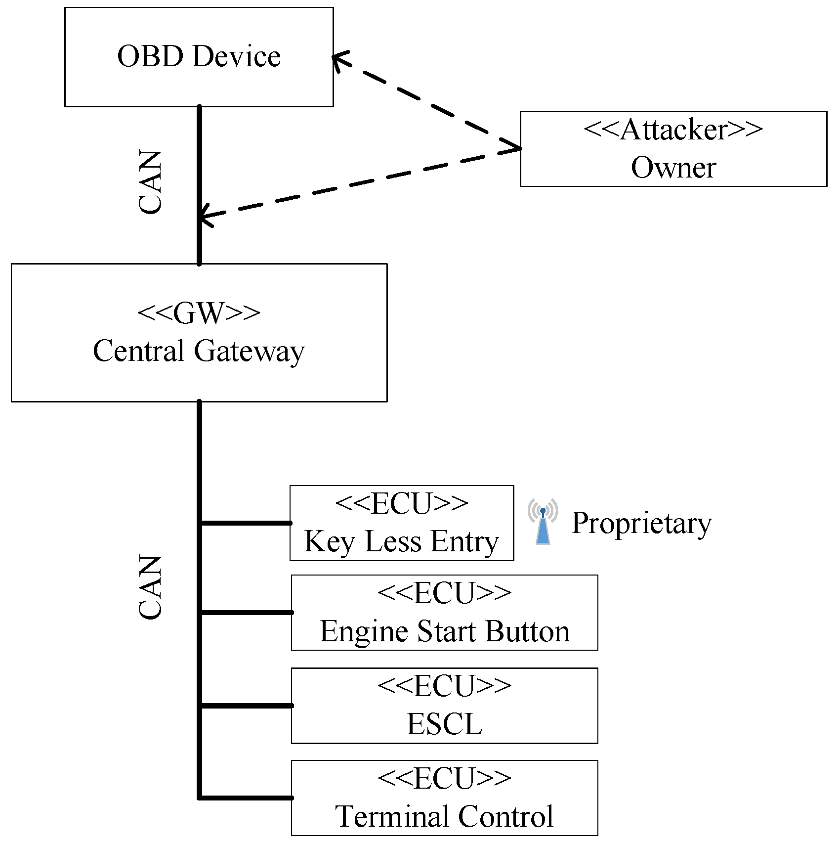
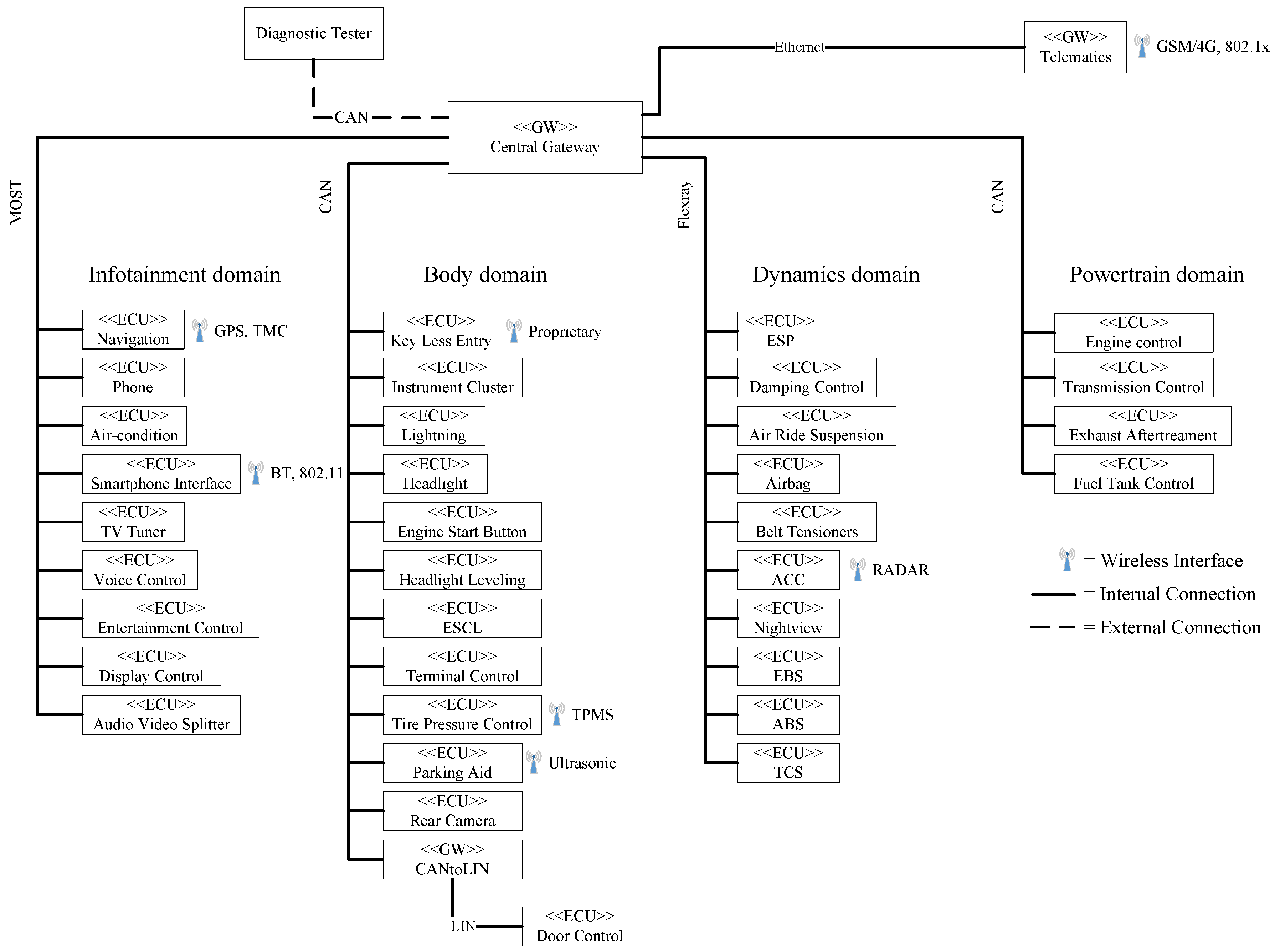
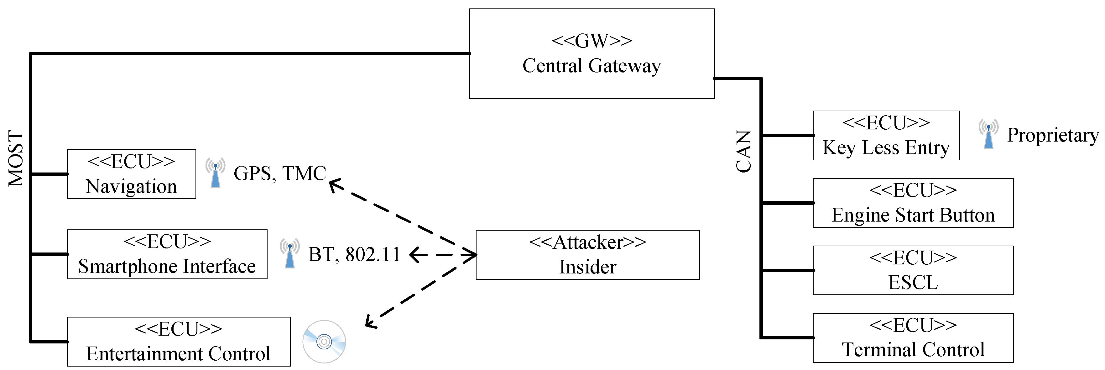
3.1. Conceptual Automotive Architecture

For an accurate mapping of the ISO 27001 to automotive, a conceptual architecture is needed. To achieve this, we divided relevant components into four main classes of systems. Hence our proposed architecture is able to model the underlying relations between different systems in a modern car, on an abstract level. Figure 4 conveys these relationships between the different systems. Particularly, these are the bus systems, control units and gateways. The diagram uses a UML2 notation with stereotypes.
Control units or Electronic Control Units (ECUs) represent the major part of electronic systems in cars. They always include a Central Processing Unit (CPU) to process information and possess sensors for gathering informations of their environment. Additionally, they control actuators to influence the vehicle’s condition, like triggering brakes. Whereas GW describes an embedded system, which operates as gateway. They are primarily used to translate bus systems and take particular importance, if the involved bus systems differ. To translate from one to another bus type, gateways apply translation matrices. These tables describe how to translate informations embedded in protocols. Besides, advanced GWs possess a firewall which controls the routing of messages between different domains.
Although ECU and GW are differing, they belong to one type of system, which we call an automotive embedded system. This membership is shown in Figure 4 by the inheritance between the class AutomotiveEmbeddedSystem an their subclasses ECU and GW. The major difference of automotive embedded systems conceming other embedded systems are characteristic features like Automotive Safety Integrity Level (ASIL) or AUTOSAR based operation systems.
Further ECUs and GWs are interconnected by means of various bus systems. To properly map these connections we propose the class BusSytem which illustrates interconnections between ECUs and between ECU and GWs. For managing of special data, like diagnostic informations, they also use protocols. Diagnostic data offer initial approaches for mechanics to diagnose and fix problems. Typical protocols for diagnostic sessions are Unified Diagnostic Services (UDS), On-board diagnostics (OBD) and Keyword Protocol 2000 (KWP). Moreover, bus systems are often standardized by ISO, for example CAN is defined in ISO 11898 and Flexray in ISO 17458. In addition, bus systems use some topology, commonly star topology and bus topology. In particular, the most used bus system CAN uses bus topology and has some main disadvantage in case of security, mainly of its topology and broadcast nature. In the same way, real time capability is also important. Especially safety relevant functions communicate exclusively over bus systems, which offer real time capability. CAN is one choice in such a context. To instantiate different bus systems in a vehicle, we create Figure 5. The hierarchical structure shows primary applied bus systems such as CAN, Media Oriented Systems Transport (MOST), Flexray and Local Interconnect Network (LIN).
Moreover, we can further structure the CAN bus in Body-CAN, Powertrain-CAN and Diagnostic-CAN. In the same way, the term Wirless is derived from Connection in Figure 5. These types of connections describes links between the vehicle itself and its environment. Exemplary, Bluetooth is used to pair smartphones with radio or navigation systems, whereby smartphones normally are in the vehicle. 802.1x connections are utilized to connect to the outside world. Particularly relevant in this context is Car2X (802.11p), where self-organizing and distributed networks are used to communicate. The concept of Car2X includes links to other vehicles or to infrastructure, like base stations on the road side. The main objective of Car2X is increasing vehicle safety. In summary, we can provide an exemplary conceptual automotive architecture in Figure 6, to which our methodology will be applied.
Although this architecture is not implemented in a car and was created by reviewing/abstracting several real-world conceptual automotive architectures, we deem it intuitive for practitioners to make the necessary adjustment to fit their architecture. Hence, the architecture directly re-uses the types ECUs and GWs of Figure 4. Additionally, we marked some ECUs with a wireless symbol in order to illustrate optional wireless interfaces. The reason for this is, we deem that wireless interfaces are the most important scope for security currently and in the future.

3.2. Automotive Attacker Model

For advanced risk management, we need a suited attacker model. The model serves to identify the significance of gathered threats. In particular, attacker models support a matching between possible attacks and the class of attacker, who is able to perform these. Although attacker models are useful to generate generic attack patterns (e.g., OWASP [25]) useful in practice, we treat vehicles as cyber-physical systems bringing together safety critical embedded system functionality and information system attack vectors. Thus, our intention is to create a domain-specific taxonomy supporting the reasoning about attacks on automotive systems. Therefore, we define an attacker model, which allows reasoning about achievable goals of attackers in vehicular networks. Our attacker model (see Table 1) identifies five different classes of attackers defined by their knowledge and skills with levels from L0 to L3 (low to high).
These levels are a qualitative measurement and can be treated as an <<enumeration>> class similar to Figure 2. Level 0 (L0) denotes no capability or no knowledge about the target. Level 1 (L1) denotes few capabilities or few knowledge. The next level (L2) denotes intermediate capabilities or knowledge. Lastly, L3 describes advanced capabilities or full knowledge about the target.
Knowledge about the target is represented by System knowledge and attack skills represented in Table 1 by Physical attack, Non-physical attack, Complexity of attack and Scaled attack. System knowledge describes any information about the target. This may be informations about a simple ECU, a complex vehicular network or complete E/E architecture. Furthermore, attack skills consist of access level to the target and abilities which an attacker could possess. For example, the access level Physical attack describes any attack which uses a wire-bound interfaces such as OBD-Port or Universal Serial Bus (USB) interface on an infotainment system. In contrast a Non-physical attack is performed on wireless interfaces like 802.1x, Bluetooth, etc. For the abilities part, the category Complexity of attack characterizes the attack complexity by the length of the respective attack vectors. In particular, a simple attack complexity means performing direct attacks, where no preconditions are required. For instance, sending a CAN message to trigger some action. Conversely, a complex attack includes multi-stage attack vectors, where an adversary must overcome a number of ECUs or security measures. Lastly, a Scaled attack enables attacking more than one vehicle, even if minor modifications of the attack are required for each vehicle.
Similarly to knowledge levels and skills, we propose five adversary types where Owner means the holder of the attacked vehicle. We do not believe he has bad intentions but he can unintentionally trigger an attack by connecting malicious hardware. Additionally, an attack can be triggered by him, in case of misuse. Thus, we deem the owner to be incapable of performing a scalable attack. In the same way, a Beginner is a person having no bad intentions and is only interested in knowing his car. Nevertheless, he can also be a relevant adversary. He differs from the previous attacker type in level of knowledge and attack complexity. Contrary to the class Owner, he is able to perform attacks, where defined entry points are used (e.g., the OBD-Port).
The third attacker type is the Tuner or thief. This attacker class has bad intentions and wants to gain a benefit from its attack. On the one hand, a tuner tries to change the vehicle’s states by adding hardware or modifying software components which are used to gain profit by selling them. On the other hand, a thief tries to break in to remove vehicle components or stealing the whole car. To achieve their goals, thief and tuner have a moderate knowledge about vehicle systems and are able to start complex attacks on wire-bound or wireless interfaces. As an example, a common attack is cracking rear lights, gaining access to the CAN and sending a message to open the doors. Additionally, they are able to perform simple attacks, which scale on a vehicle fleet.
Likewise, the class of Insider is able to perform scalable attacks, whereas he can start advanced attacks on physical or non-physical interfaces. Further, he can implement complex attacks having long attack vectors. Therefore, he can perform multi-stage attacks where several ECUs or GWs are involved. Consequently, he has a deep knowledge of vehicle systems, which is the reason as to why the class of Insider has expert knowledge and skill (i.e., Level 3 in Table 1).
The class of Organized group represents a black hat team. They have nearly unlimited resources and possess information channels where secret details of vehicle systems can be obtained. Hence, they are able to perform complex attacks on every interfaces, which can scale on different vehicle fleets. An organized group can be represented by hacker collectives or governmental agencies.

3.3. Automotive Controls

Without doubt, the vehicular attack surface is special and hence we want to propose adapted countermeasures which can be applied. In particular we deem to propose lightweight measures which can be applied on low performance devices. These devices are common to the automotive domain and not always able to handle cryptographic algorithms like AES or RSA. Additionally, bus systems like CAN have to fulfil real-time capability. This feature can be violated if intensive computation of bus data is needed.

3.3.1. Plausibility Checks

Plausibility checks are one measure which can help in some situations. They are applicable if attack success is linked to a vehicle condition and thus to a physical value, like vehicle speed. For instance, execution of diagnostic functions are such a case. Here, a vehicle speed of v = 0 is assumed to successfully trigger a function. In other terms, this means that functions should not be able to trigger if v 0 . For these situations, we deem the listed concept can be applied. Table 2 presents requirements for values which are used to implement plausibility checks.
Obviously, the recommended concept is adapted to ASIL. We believe this is necessary to address safety requirements. In case of QM we guess, a value read out from local bus is sufficient to apply plausibility checks. We only propose that the value should be taken from same vehicle domain. This means, the used value should be created or measured in the same domain as the plausibility check. Thus, translation faults between bus systems can be excluded.
If ASIL A has to be observed, we deem it necessary to demand an integrity check for the taken value. Consequently, the attack surface of malicious value modification is reduced, since the attacker needs the calculation rule for computing a checksum. In contrast, replay attacks are not preventable using checksums. Hence, we deem to claim integrity and authenticity checks if ASIL B has to be implemented. Accordingly, cryptographic algorithms have to be applied for obtaining trusted authenticity. Fortunately, only the checksum is needed for computation in our case. As a result, the impact of complex computations are reduced and make the concept suitable to the automotive domain. As an example for obtaining integrity and authenticity, Keyed-Hash Message Authentication Codes (HMACs) are a possible choice.
Switching to the next higher ASIL, we propose the use of integrity and authenticity checks and also a second value. The second value should also be checked for integrity and authenticity. Furthermore, it should be taken from a different bus as the first value. This concept reduces likelihood of bypassing plausibility checks if attackers are able to compute valid HMACs for the first value. Indeed, the second HMAC has to be created by a second key.
Lastly, we propose integrity and authenticity checks in combination with a second local value for ASIL D. This approach offers a second bus independent value which prevents bypassing plausibility checks. Significant is this approach, if attackers are able to emulate bus systems and their security features. A second value will then prevent a successful attack by delivering further information. Since attackers are able to emulate bus systems, we deem it necessary to evaluate a none-bus value. Fortunately, we can derive such comparable values. In case of the value speed, we can derive replacement values from sources like GPS, camshaft speed, rpm with gearbox setting, wheel speed, etc.

3.3.2. Cryptographic Counters

Similarly to the measures before, cryptographic counters are able to improve attack resistance. For instance, they can prevent replay attacks representing one important attack class in vehicular networks. The importance of this class, is justified with CAN’s broadcast nature and its lack of authenticity checks. As a result, bus members are not able to detect forged messages or the presence of an invader. Thus messages can be eavesdropped and replayed at any time. If message-counters are embedded in the CAN frame, sender and receiver can compare the number of received or sent messages to detect discrepancies. This information will give the ability to identify illegal send messages which can than be ignored. In case of attackers, who are able to eavesdrop messages and modify embedded counters, we deem to use cryptographic counters to prevent malicious modification. Indeed, selected algorithms should allow integrity and authenticity checks. For example, applying HMAC on counter value can achieve this aim.

3.3.3. Firewall Based on CAN Matrix

As a last measure, we propose firewalls between different networks and/or bus systems. To simplify setting up this measure, we propose to use available CAN matrices. A CAN matrix provides informations about sending or receiving of messages by any ECU or gateway. Consequently, filtering of messages by CAN identifier is feasible. Even though this concept will not avoid replay attacks when attacker gains access to the associated subnet. However, rejecting of none associated messages is possible. In particular, this is relevant in case of multi-stage attacks. Here, different subnets are involved and attackers have to send messages from one to another network or bus system (gateway in-between). Hence, interrupting this attack path can protect from consequences. Furthermore, we deem a combination of matrix based filtering and cryptographic counters as a powerful countermeasure against relevant attacks like replay and malicious message injection.

4. Application of our Methodology

We illustrate the application of our method in the following. Firstly, we show how the ISO 26262 compliant hazard analysis works. Secondly, we present how the artefacts and analysis results from the safety analysis are re-used in a ISO 27001 compliant threat analysis.

4.1. Hazard Analysis Compliant to ISO 26262

We illustrate our method on an example of an electronic steering column lock (ESCL) system, which was presented at the “VDA Automotive SYS Conference 2012”, 18/20 June 2012, in Berlin, Germany.

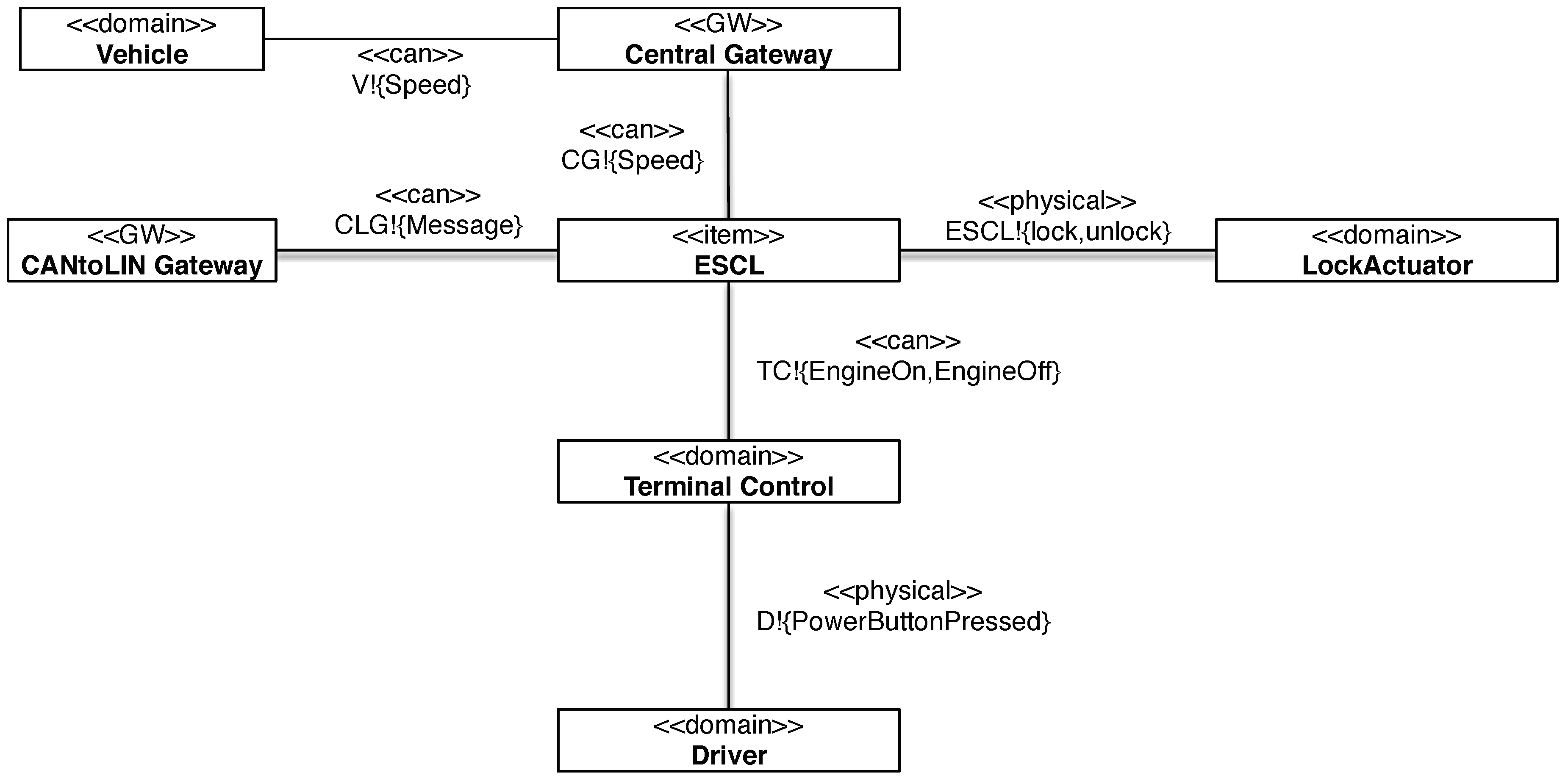
4.1.1. Safety-Step 1: Provide an Item Definition

The main function of the ESCL is to provide lock and unlock commands to the lock actuator automatically to enhance theft protection for vehicles with a power button instead of a standard key. The context diagram in Figure 7 shows the item, i.e., the ESCL and the elements in the environment, namely the the driver, the lock actuator, and the vehicle. The item controls the lock and the unlock commands, and the lock actuator observes these phenomena. The driver presses the power button to crank or stop the engine. The vehicle moves at a certain speed and therefore controls the phenomenon Speed.
Table 3 shows the functional requirements of the ESCL. For both requirements R01 and R02, it shows which domains of the item’s environment are constrained (see column ≪constrains≫) and which domain the requirements are referred to (see column ≪refersTo≫): The lock actuator is constrained. The driver and the vehicle are referred to since they together provide necessary information to deduce if the driver wants to drive or not.

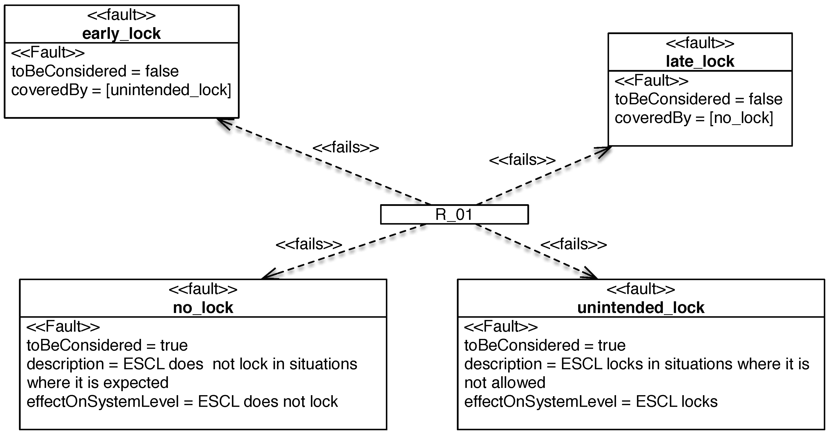
4.1.2. Safety-Step 2: Instantiate Fault-Type Guide-Words

To start with the hazard analysis, we look at the lock actuators constrained by the requirements R 01 and R 02 , and investigate both functional requirements according to the guide-words.
Figure 8 shows some of the fault types assessed for R 01 . For the guide-word “no”, the fault is that the ESCL does not lock in situations where it is expected. For the guide-word “unintended”, the fault is that the ESCL locks in situations where it is not allowed. For the guide-word “early”, the fault is the same as described in fault unintended_lock. For the guide-word “late”, the fault is either no problem, or in case of a long delay the same as described in fault no_lock. The faults related to all other guide-words are either mapped to “no”, “unintended”, or are not relevant since the locking is a binary decision and cannot be “less” or “more”.
Additionally, we have to describe the effect on system level. For example, for unintended locking, the effect on the system level is that the ESCL locks the steering column. The effect on the vehicle level is that the vehicle is not steerable. For R 02 , the procedure is the same.

4.1.3. Safety-Step 3: Situation Classification

The situations are classified according to the item’s functionality. In Figure 9, the situation classification using our profile is depicted.
The situation “driving at speed” is classified as being relevant, because a hazard may occur if the vehicle is moving and the steering column is locked. The situation “maneuver” (including, e.g., parking, driving backwards) is marked as being not relevant, because for the ESCL system the maneuvering hazards are the same as for “driving at speed”. The situation “standstill” is classified as being relevant, because a hazard may occur if the vehicle is “parked”, and the steering column is not locked. The effort necessary for the situation classification is reduced, because it is not necessary to rate these detailed situations. The situations “being towed” and “rolling” are classified as being relevant because they consider the system state where the engine is off.

4.1.4. Safety-Step 4: Hazard Identification

In the next step, the hazards are identified. For this reason, all considered faults are combined with all situations where the fault leads to a problem. These are the ones having the attribute toBeConsidered=true. It is possible to have more than one fault that causes the hazard, and the hazard can be in place in different situations. Some combinations are not needed in the hazard analysis, e.g., the situation standstill does not need to be combined with the fault of unintended locking, because locking is intended in this situation.
Figure 10 shows the hazard that can occur when the vehicle is moving at speed. It may be caused by unintended steering column locking. To describe the hazard, first the effect on vehicle level is described. For the previously described fault, the effect on vehicle level is that the steering is locked and the vehicle is not steerable. The hazard is the “loss of steering control (locked steering) when driving at speed”. The hazard refers to the risk assessment performed in the next step.
Note that we do not introduce additional hazards during the security analysis. We complete the hazard elicitation in this step completes. The security perspective with its attacker perspective just add further causes for hazards. For example, the locking of the steering column wheel while driving at speed can be caused by an attacker.

4.1.5. Safety-Step 5: Hazard Classification by Severity, Exposure, and Controllability

The above-mentioned hazard is rated according to its severity, exposure, and controllability as depicted in Figure 10. The highest severity level S3 is chosen, because a locked steering column lock at speed can lead to death or life-threatening injuries when the vehicle hits, e.g., obstacles near the road, pedestrians, oncoming traffic, or obstacles on the track. The exposure level is E4, because steering is necessary in the mentioned situations and in all situations with high speed, which are more than 10 % of the driving time. The highest controllability level C3 is chosen since no lateral control by steering is possible. The driver can only intervene by braking, but in case of high speed the driver cannot avoid the consequences of the hazard. Hence, ASIL D is automatically deduced from this classification.

4.1.6. Safety-Step 6: Define and Verify Safety Goals

The described hazard can be addressed by a safety goal as depicted in Figure 11. The same safety goal can also address other hazards (not shown here). To prevent the hazard, the safety goal is that “locking of the steering column when the vehicle is moving shall be prevented”. This safety goal refers to the vehicle since it indicates if the vehicle is moving and constrains the steering column lock by preventing the lock. Since we cannot accept steering column locking even for a certain time, the fault tolerance time is not applicable. For other safety goals, e.g., prevention of braking intervention, the fault may be acceptable for a short time period.
We model the relations between faults, hazards, and safety goals, depicted in Figure 12. The information in this model can be converted into a table (see Table 4) for documentation purposes. The safety goals (e.g., PreventLocking) and faults (e.g., unintended_lock) referenced by or referencing multiple other elements will appear in more than one table row. Since the hazard Theft (see Figure 12) has no ASIL A, B, C or D assigned, it is not addressed by a safety goal but by the requirement EnsureLocking.

4.1.7. Safety-Step 7: ISO 26262 Review

To support the reviews, the validation conditions listed are executed on the complete case study. These validation conditions check the consistency and correctness of the model. That is, we check
  • whether each relevant functional requirement in the item definition is considered,
  • whether the hazard and risk assessment is aligned with the supplier’s assessment, and
  • whether the hazard and risk assessment is consistent with ISO 26262 description.

4.2. Threat Analysis Compliant to ISO 27001

We report on how a ISO 27001 compliant threat analysis looks like in the following and provide examples for the second part of our method.

4.2.1. Security-Step 1: Get Management Commitment

The ISO 27001 standard dedicates its entire Section 5 to the importance of management commitment for implementing an ISMS. ISO 27001 Section 5.1 contains demands for management commitment proofs and provisioning of sufficient resources.
The management commitment for implementing an ISMS according to the ISO 27001 standard is important, because without the commitment of sufficient staff and resources the ISMS implementation a satisfactory security level cannot be guaranteed. In addition, the publicly available examples of ISMS documentations, e.g., the so-called ISMS toolkit [26] defines this also as the first step of establishing an ISO 27001 compliant ISMS. Note that the management commitment is based upon our item definition (Step 1 of the Hazard Analysis process).
We provide a template for management approval of the ISMS, presented in Table 5. The template structure is inspired by Section 5.1 of the ISO 27001 standard. The first column in the template lists the management commitment and the second the natural person who is responsible for this concern or the tasks or resources required to address the concern.
The template consists of two parts: Management Commitment states the responsible persons for the overall establishment of the ISMS and vital concerns towards its success, e.g., criteria for risk acceptance. Resource Management states the required resources for establishing an ISMS. We use our running example with the template to show an integrity and an availability goal in Table 5.

4.2.2. Security-Step 2: Define ISMS Scope

The item definition of the ISO 26262 Hazard Analysis already has a scope, that includes all safety relevant domains. To reason about the security of the safety-relevant functionality, we need to expand the scope towards the points of attack used by attackers to access the item.
Since some attack vectors are not interesting to our exemplary analysis, we conduct the analysis under the following assumptions:
A 1
The firmware of all ECUs on all buses (including CAN) is secure from tampering by attackers.
A 2
Updates to the firmware of ECUs have security guarantees enforced by the update mechanisms concerning their integrity (e.g. they are signed).
A 3
The shop and repair garages do not carry out any attacks on the cars while in maintenance. This includes security guarantees towards the tampering of software/hardware used in this maintenance.
A 4
Attackers do not have access to any maintenance or diagnosis tool/software typically only available to shop and repair garages.
A 5
All signals from other buses (including other bus types) must pass through a dedicated gateway (as shown in Figure 6).
Under the assumptions above, we extend the scope of the item to include any communication with ECUs directly on the same bus. If there are gateways on the bus, these are always added. In case any signals relevant for the item are handled via the gateways, these signals are connected to the respective gateways. The extension of the scope using this method is sensible, since an attacker may only directly attach to the bus or must go via a gateway, which may act as a firewall creating a separate zone of devices. Thus, the scope is similar to that of a demilitarized zone (DMZ) of network systems.
In Figure 13, the exemplary item definition of Figure 7 is extended to include any communication with ECUs. This includes the Terminal Control ECU and the Central Gateway, which relays the information of the vehicle speed from the can bus of the powertrain domain. In addition, the CANtoLIN Gateway is added as an attacker may send messages via this gateway. By having this scope, we now have a comprehensive overview of all safety relevant messages and their origins on the bus. However, we neither know their origin on other buses nor if they have been tampered with.

4.2.3. Security-Step 3: Identify Assets

ISO27001 does not consider asset identification as mandatory [28] (p. 4). However, the risk identification in Section 6.1.2 in the standard could be supported by identifying assets and their vulnerabilities and threats. Some controls in Appendix A even refer to assets such as control A8-Asset management.
We propose the following technique to identify assets. We iterate over all domains and the phenomena in the scope shown in Figure 13 and decide for each element if it is an asset or not. Note that we assume the physical devices are outside the reach of an attacker (cf. assumptions listed in Step 2) and that we focus in this work on information assets in the sense of ISO 27005 [29] (p. 11). The reasoning behind this constraint is that we focus on information security issues, in which malicious treatment of information leads to harm of physical devices or even humans. In this sense, the protection of human is achieved by the protection of the information. The threats caused by physical attacks on the car and its inhabitants have to be treated during the establishment of the ISO 26262 process (e.g., the hazard theft in Table 4). We show the results in Table 5.
The ISO 27001 standard [6] (p. 4) demands a rating of all threats with regard to the losses in availability, confidentiality, and integrity they cause. In the automotive domain the main concern of information assets is integrity and availability. Confidentiality is not important for the protection against an attacker, because knowing the content of the messages does not harm any asset or subsequent physical devices of humans. The primary concern in this scenario is subsequent harm to physical devices of humans by malicious behaviour of a cyber attacker. However, integrity is of utmost importance, because changes in messages may result in unwanted behaviour of the vehicle and subsequent harm to passengers, and road users. Note that integrity is also part of a safety analysis, but only the accidental change of a message that results in unreadable content. In security, we address the sending of syntactically correct content with unwanted content, which is not addressed during a hazard analysis. In addition, the absence of messages also cause similar results. Hence, we have to also consider availability issues during the threat analysis. Nevertheless, safety mechanisms may already deal with availability problems, since this is part of the hazard analysis.
We show the results in Table 6, which states the relevant scope element, the answer if this is an asset and a reasoning in case the scope element is not an asset.

4.2.4. Security-Step 4: Analyse Threats

To apply threat assessment, we reuse information provided by hazard identification and the proposed attacker model in Table 1. Consequently, we show security threats which cause hazards depicted in Figure 12. Indeed, we make some assumptions to the proposed architecture in Figure 6. First, we are supposing that key fob is in the car and detected by Key Less Entry ECU. Second, the Engine Start Button ECU is not directly wired to ESCL. Third, relevant information like, key fob is detected, engine start button pressed and ESCL locked/unlocked are embedded in messages. Furthermore, every message is distributed over the entire architecture by the Central Gateway. It means in effect, every message can be seen by each ECU in Figure 6 and on the OBD-Port. In addition, the ESCL gets unlocked when key fob is detected and the engine start button is pressed. Locking of ESCL requires a turn off message from the Engine Start Button ECU only. The absence of key fob does not imply turning off the engine, i.e., key fob has no influence on ESCL locking. Additionally, the default state of ESCL is locked until the unlock message is received.
For further explanations, we use a subset of ECUs from Figure 6 as attack surface and one attacker type. Thus, the first attack vector is presented in Figure 14 by a physical access to the OBD-Port and Owner as attacker type.
As stated before, we do not believe that owners have bad intentions but they can unintentionally trigger an attack. For this purpose, we assume a connected OBD-Device. Such devices are not hypothetical. In particular, insurances offer black boxes connected to the OBD-Port analysing drivers driving style. Furthermore, several OBD-Devices for smartphone applications are freely available. Unfortunately, no costumer can check if such a device is malicious. Therefore, it is not far-fetched, to assume (maliciously) manipulated devices. A sample of possible consequences are listed in Table 7.
Each threat in Table 7 owns a unique ID for mapping it to the risk assessment. Furthermore, a description for each threat is given, enabling experts to understand the relevant threat and its vulnerabilities. Lastly, the third column shows the associated hazard which can be triggered by the relevant threat. For instance, Threat 1 describes a physical attack surface where the owner has connected an OBD-Device to his vehicle. We assume the OBD-Device as malicious, sending Engine Off message over CAN to Central Gateway. Afterwards, the gateway will relay the message to ESCL ECU and ESCL. Similarly to the previous threat, a message from OBD-Device is sent to cause Threat 2. In contrast to Threat 1, a diagnostic message is used which can previously identified. In particular, such messages can be found in freely available sources like the producer’s manual or by extracting informations from diagnostic testers.
Similarly to the first sub-architecture in Figure 14, we present a second attack surface in Figure 15. Here, a second domain is added, compared to the first example. Furthermore, the attack surface shows one wire-bound and two wireless weak points where no physical access is needed.
In this attack surface, Navigation, Smartphone Interface and Entertainment Control are starting points for attackers. Hence this requires more sophisticated persons. Therefore, we believe attacker class Insider is able to exploit the shown vulnerabilities to trigger threats. Although the CD-ROM symbol on Entertainment Control suggests physical access as attack precondition, it is not needed. This can be explained by attackers which sell malicious CD-ROMs over online platforms to vehicle owners. For exploiting vulnerabilities on the Navigation and Entertainment Control ECU, we assume that attackers are able to set up appropriate wireless transmitters. Therefore, we believe the listed threats in Table 8 are feasible.
Table 8 lists three possible threats for the posed attack surface in Figure 15. First, with Threat ID 3 a TMC based attack is described. Therefore, the attacker sets up a TMC transmitter sending modified messages which cause buffer overflow in the Navigation ECU. Afterwards he gains control of the Navigation ECU which enables him to send Engine Off or Lock ESCL messages to lock ESCL. Threat 4, is caused by the same messages but on different wireless interfaces. In particular, Bluetooth and WLAN are used to enter vehicle’s network. Since most of these interfaces are protected by password, we assume he is able to brute force the password. That is not unreasonable in case of performed attacks on this interfaces. The last entry with Threat ID 5, describes an attack consisting of a malicious CD-ROM and an ESCL Reset message. For this, the attacker creates a modified Windows Media Audio (WMA) file which causes an buffer overflow in the Entertainment Control ECU. After this, he can send the ESCL Reset message to the Central Gateway which forwards the message to the ESCL ECU. As a result, ESCL will look.

4.2.5. Security-Step 5: Conduct Risk Assessment

The ISO 27001 standard states that managing risk by implementing security controls as a main goal of the process the standard creates. The standard mentions this already on page 1 and risk assessment is a part of risk management. In particular, ISO 27001 Section 6.1.2 concerns information security risk assessment. Section 6.1.2a) shall establish risk acceptance criteria and criteria for performing risk assessment. Section 6.1.2b) ensures that risk assessment produces comparable results. Risk identification is demanded in Section 6.1.2c), risk analysis in Section 6.1.2d), and risk evaluation in Section 6.1.2e).
We propose the following risk assessment technique. We define scales of likelihoods, consequences, and risk evaluation criteria, which rely on the values assessed during our hazard analysis. Risk assessment can be conducted either quantitatively or qualitatively. Quantitative risk assessment demands that the likelihood and consequences scales contain numeric values. These have to express in which time frame a risk is likely and what the consequences are, e.g., the number of affected persons. The system in our example has not fully being build and deployed in a large scale yet. Meaning that the functionality is only partially available at this point and only implemented in small testbeds. This is the reason why we express the likelihood and consequences tables using qualitative scales that do not contain numbers. These are a starting point for risk assessment, and should the numeric values become available, a quantitative risk assessment should be done. We illustrate our likelihood scale in Table 9 and the consequences in Table 10.
The exposure values defined in ISO 26262 provide a baseline for establishing the likelihood values for the ISO 27001 risk assessment. The reason is that the likelihood of an attack happening during the lifetime of the car is related to the total life time of the car. Therefore, we propose a mapping from the Table 11 to support this task.
The severity values defined in ISO 26262 provide a baseline for establishing the consequences values for the ISO 27001 risk assessment. The values provides the damages to humans that can occur. In addition, we have to consider the values of controllability that state how much of the hazard can be controlled. Therefore, we propose a mapping from the Table 12 to support this task. Note that in case of the combination of severity and controllability does not exist in the table, the worst risk value has to be used.
We use these scales for all assets elicited in the scope, and we use the risk evaluation criteria specified by the matrix in Table 13. The matrix shows the acceptable combinations of likelihoods and consequences in light shading, and unacceptable combinations in dark shading. Afterwards, we map the ASIL values to our consequence and likelihood scales as shown in Table 14.
We assume Threat 1 can be triggered by owner or beginner, Threat 2 by beginner, Threat 3 and 4 by tuner or thief and lastly Threat 5 by insider. Since all threats cause same hazard, namely Steering control loss, we use the same consequence rating for them, i.e., Major. We decided to use the scale Major due to the fact that breaking an ESCL lock is possible for strong people. Hence, an accident could then be prevented. Besides, reducing speed by use of brakes could also prevent accident. We apply the threats from Table 7 and Table 8 to the risk evaluation, shown in Table 15 in the following.

4.2.6. Security-Step 6: Reason about Controls

Section 6.1.3 in the ISO 27001 standard concerns information security risk treatment. ISO 27001 demands in Section 6.1.3a) that controls from all possible sources can be selected, but the standard demands in Section 6.1.3b) that these controls have to be mapped to controls in ANNEX A. We provide refinements of the ANNEX A of ISO 27001 controls in the form of the automotive controls presented in Section 3.3. We illustrate the refinement by mapping the ISO 27001 controls to our automotive controls.
We exemplary focus on Threats 1, 2 and 5 from Step 4. The remaining threats are treated in a similar manner. To counter Threat 1 with its replay nature, an application of cryptographic counters is feasible. Accordingly, ECUs Key Less Entry, Engine Start Button and lastly Terminal Control have to verify the counter value, if message Engine off will be seen on CAN. Furthermore, they have to increase the counter value if they send corresponding messages. Additionally, the counter value has to be protected against malicious manipulation. Therefore, ECUs compute HMAC of the counter value and embed this information in CAN frame. Hence, each ECU can see the counter value and corresponding HMAC for message Engine off. As a result, the attacker can still send message Engine off, but the message will be rejected by the corresponding ECUs. The reason for this is, that the attacker can send the message and perhaps manipulate counter value, but he will not able to create the correct HMAC. Therefore, a discrepancy can been seen by the ECUs and malicious message will be rejected.
To counter Threat 2 which is caused by replaying diagnostic message, an application of plausibility checks is feasible. Therefore, we use the value speed shown in Figure 13 as input for plausibility check. In case of the ASIL D corresponding hazard, we are forced to use integrity and authenticity checks for value speed and also a local physical value. Unfortunately, there exist no such value in our architecture. Hence, we propose to change the architecture in a way where Engine Start Button is directly connected to ESCL ECU. In fact, this change is small in case of the closeness of ESCL and Engine Start Button ECUs and there is a high likelihood of available connectors on both sides. Thus, only the ESCL and Engine Start Button ECUs are minimally affected and other systems are not impacted at all. Afterwards, we are able to fulfil the first part of the requirements in Table 2. Lastly, the second part can be fulfilled by applying HMAC on the value speed. In addition, application of CAN based firewall is feasible to increase protection level. Thus, the firewall is implemented on the central gateway blocking the message Lock ESCL from sending and receiving on OBD-Port. Hence, it will be practically impossible for the attacker to send or see the message Lock ESCL on the OBD interface.
In the same way, Threat 5 can be treated. Here, plausibility checks and firewall is feasible again. Hence, value speed is picked up again to prevent locking ESCL while driving ( v > 0 ). In particular, if vehicle is moving and message ESCL Reset will occur, the message will be rejected by ESCL ECU which is a logical step. Additionally, the CAN based firewall can prevent sending malicious messages like ESCL Reset from one to another domain by filtering traffic which will decrease the attack surface.
We provide an overview in Table 16 of the threats, automotive countermeasures, ISO 27001 controls and the hazard caused by an attacker they should prevent. This table can be used as a basis for reasoning about the cost versus the gain of applying the countermeasures. ISO 27001 demands to the risk estimation for each asset and the established controls to reduce the risk to acceptable levels.

4.2.7. Security-Step 7: Design ISMS Specification

The ISO 27001 standard demands a documentation of the ISMS. In particular, Section 4.3.1 demands a documentation of several parts of the ISMS. A list is provided in the column ISO 27001 Documentation of Table 17. Note that the “documents and records may be in any form or type of medium.” [6] (p. 8). Hence, we do not elaborate on their form in detail. Furthermore, we propose a mapping in Table 17 of the generated artifacts from our method to the documentation demands of the ISO 27001 standard. The column ISO 27001 Documentation states the artifact that relates to a specific part of the ISMS. The column Steps states the steps of our method that describes how to create the artifacts mentioned in the column Support from our Method.
We describe our mapping in Table 17. Here, we use our management commitment template to document the ISMS policies and objectives. The scope and boundaries of the ISMS are documented using our scope description and the assumptions concerning security for that scope. The procedures and controls are documented as part of our chosen security controls. The risk methodology is our described risk approach, and the risk assessment report uses the asset identification, threat analysis, and risk analysis approaches. The risk treatment plan contains the risk estimation for each asset and the established controls to reduce the risk to acceptable levels. Note that we simply provide an overview of the required documentation at this point for the sake of brevity. As is the case with ISO 26262, it must be validated whether threat analysis and risk assessment is aligned with the supplier’s assessment. However, security is not compositional and additional measures may need to be taken to assure the security of the all safety-critical systems.

5. Related Work

We report on existing hazard analysis, ISO 27001 support techniques, threat analysis approaches, and automotive safety and security approaches in the following. We did not discover that shows in a structured and stepwise method how ISO 26262 hazard analysis and ISO 27001 security analysis can be combined.

5.1. Hazard Analysis

Two hazard analysis methods are compared by Törner et al. [30]. The paper shows that the adapted functional failure analysis (FFA) is less time-consuming than the method of the European Space Agency (ESA method). The method presented is this paper is based on the results of [30].
The entire safety lifecycle including hazard analysis and risk assessment is presented by Baumgart [31]. Our method can complement the hazard analysis of Baumgart’s safety lifecycle.
The Safety Management System and Safety Culture Working Group provides guidance on hazard identification by different means, e.g., brainstorming, HAZOP, checklists, FMEA [32]. Their results are considered in the method presented in this paper.
Jesty et al. [33] give a guideline for the safety analysis of vehicle-based systems, including system analysis, hazard identification, hazard analysis, identification of safety integrity levels, FMEA, and fault tree analysis. Their work also uses the HAZOP guide-words, but they focus on the safety integrity level as defined in the IEC 61508 and not on the ASIL from ISO 26262. Jesty et al. additionally address FMEA and fault tree analysis for analysing existing systems, but do not consider a model or validation conditions.
In contrast to our work, which focuses on the determination of necessary risk reduction, following papers describe model-based approaches specific for later development phases, when the system is already designed and not the determination of necessary risk reduction:
Papadopoulos and Grante [34] propose a process that addresses both cost and safety concerns and maximizes the potential for automation to address the problem of increasing technological complexity. It combines automated safety analysis with optimization techniques.
Li and Zhang [35] present a comprehensive software hazard analysis method, which applies a number of hazard analysis techniques, and the proposed method is applied to a software development process of a control system. The described method for hazard analysis is similar but less detailed than ours.
Mehrpouyan [36] proposes a model-based hazard analysis procedure (based on SysML models) for the early identification of potential safety issues caused by unexpected environmental factors and subsystem interactions within a complex safety-critical system. The proposed methodology additionally maps hazard and vulnerability modes to specific components in the designed system and analyzes the hazards.
Zhang et al. [37] propose a comprehensive hazard analysis method based on functional models. It mainly addresses fault tree analysis and FMEA.
Giese et al. [38] present an approach that supports the compositional hazard analysis of UML models described by restricted component and deployment diagrams. It also starts with environment models, but then focuses on the safety analysis of the design.
Hauge and Stølen [39] introduce the SaCS method. The method provides guidance on how to select and use patterns for the development of safety control systems. The patterns are categorized into process and product patterns. This work differs from our own, because we focus on specifically on early hazard analysis and provide detailed guidance.

5.2. ISO 27001

Calder [17] and Kersten et al. [40] provide advice for an ISO 27001 realization. In addition, Klipper [19] focuses on risk management according to ISO 27005. The author also includes an overview of the ISO 27000 series of standards. However, none of these works consider to use security requirements engineering methods.
Cheremushkin et al. [41,42] present a UML-based meta-model for several terms of the ISO 27000, e.g., assets. These meta-models can be instantiated and, thus, support the refinement process. However, the authors do not present a holistic approach to information security. The work mostly constructs models around specific terms in isolation. The CF of Fabian et al. [43], on the other hand, presents a holistic framework for information security.
Mondetino et al. investigate possible automation of controls that are listed in the ISO 27001 and ISO 27002 [44]. Their work can complement our own.
Beckers et al. [45] propose a common pattern for the cloud computing domain to support context establishment and asset identification of the ISO 27000 series. That work can also complement the work presented in this paper.
Fenz et al. [46] introduce an ontology-based framework for preparing ISO/IEC 27001 audits. They provide a rule-based engine which uses a security-ontology to determine if security requirements of a company are fulfilled.

5.3. Automotive Safety and Security

Automotive security and its impact to safety relevant functions is a relatively new area. Fortunately, the interest to this field grows continuously over the last years due to the growing number of software functions and their attack surface in vehicles. There exist several publications, presenting weaknesses in vehicles. One comprehensive collection was carried out by Miller and Valasek [47]. In this publication twenty attacks can be found which exploit different vulnerabilities. In the same way Koscher [48] and its research group uncovered twelve attacks against different automotive functions. Furthermore, Checkoway [49] et al. obtained access to the CAN by using an update feature of the on board CD player. They also showed that a special build WMA file is sufficient to infiltrate a car’s CD player. Additionally, the researchers Studnia [50], Aijaz [51] and Schröder [52] apply attacks using physical and non-physical access to vehicles. In particular Schröder was able to create a ghost car which leads to an emergency braking. He forged position messages on Vehicular Ad Hoc Networks (VANETs) manipulating pre-collision systems. In the same way, we collected and found several vulnerabilities in public and in our research [53,54].
One approach, for improving safety in case of security is given by Glas [55] and its group. They assume a security engineering process fitting functional safety and security together. To do so, they propose misuse cases for security, trying to identify threats which could cause potential hazards. Afterwards, countermeasures are mapped to these identified threats, reducing likelihood of hazards. Regrettably, they only compare safety and security risk models, but do not provide an approach for handling both together.
Klauda [56] et al. try to map security weaknesses to suppliers where they mainly develop and supply core components for modern cars. They provide a proposal for a jointly development process, regarding to safety and security. Therefore, they start with an item definition. Afterwards, they consider for the safety part a hazard and risk analyse with goals and measures. For the security part, they consider a risk analyse with security objectives and measures. Both is done in parallel. Unfortunately, the do not go in details describing each part more precisely.
Lastly, SAE International publishes in January 2016 the J3061 standard [57], as a guideline to automotive security. The standard is called “Cybersecurity Guidebook for Cyber-Physical Vehicle Systems” and offers a comprehensive picture for a complete Automotive Security Development Lifecycle (ASDL). The guidebook starts with a glossary of security terms for common understanding. Therefore, it guides through the entire development process (v-model) to integrate safety and security. To address this integration, safety and security are linked together on defined milestones, like specification of SW requirements, architectural design, etc.. Nevertheless to its completeness, no modelling examples are given to support the guidelines. Furthermore, a practical combination of the most used security standard series ISO 2700x is missing. As a result, security beginners or engineers which have worked with ISO 2700x, had to start form an early stage. Nonetheless, the SAE J3061 is the most comprehensive guideline for security in cars, right now. Unfortunately, the standard is not sufficiently distributed in public so far. Therefore, it is not possible to make a statement of its future.

6. Conclusions and Future Work

In this paper, we have proposed a new comprehensive and holistic approach compliant to ISO 26262 for safety and ISO 27001 for security for safety-critical automotive software systems. Based on our previous work on hazard analysis and risk assessment compliant to ISO 26262 [10], we create a seamlessly integrated security lifecycle for safety lifecycle artifacts. Instead of using a one size fits all solution (e.g. encrypting all bus communication), we create a process to tailor security measures specifically to safety requirements. This process is compliant to the state-of-the-art security standard ISO 27001 and consists of seven consecutive steps that are based on our previous work [11] that supports ISO 27001 establishment, as well. In this work, we focus the automotive domain. Each of the seven steps directly re-uses the safety lifecycle artifacts of the hazard analysis and risk assessment to perform threat analysis and risk assessment for security. All steps can be performed after completely performing safety analysis or intertwined after each step of the safety analysis to allow parallelization and reduce the time required.
The approach uses novel automotive attacker models classifying attacker in the automotive domain for threat assessment and supplementary automotive controls as measures to mitigate/prevent attacks after risk assessment. The attacker models range from the owner of the car accidentally attacking it to organized groups like governments performing large-scale attacks. The automotive controls extend the controls given by ISO 27001 by adding measures to automotive safety including plausibility checks, cryptographic checks and firewalls between buses. The effort to implement such measures is lower than one size fits all solutions and allow the tailoring to safety requirements.
In the future, we plan to evaluate our approach. Using a (large-scale) case study, we aim to demonstrate its efficiency and effectiveness in securing safety-critical automotive software systems. In addition, we want to get industry feedback on our approach to address any issues w.r.t. its practical applicability. We also plan to extend the approach to the development and production/operation phases of the ISO 26262 standard with the aim to cover the complete safety/security lifecycle. In addition, we will provide a method for resolving conflicts between safety and security requirements, as well provide an analysis approach for possible conflicts between security mechanisms and safety mechanisms. Moreover, we are planning to use patterns of successful established ISMS to reduce the effort for realizing the security process in the future. Furthermore, we want to extend the attacker models to capture hardware/side-channel attacks as well as attacks in the garage. For this extension, the respective automotive controls also need to be added.

Acknowledgments

We thank the anonymous reviewers for their inspiring comments. This work is part of TUM Living Lab Connected Mobility (TUM LLCM) project and has been funded by the Bayerisches Staatsministerium for Wirtschaft und Medien, Energie und Technologie (StMWi). Furthermore it is part of the SAFE ME ASAP project (number 03FH011IX5) funded by the German Federal Ministry of Education and Research (BMBF). The work has been supported by ITK Engineering AG as part of two innovation projects.

Author Contributions

All authors contributed equally. All authors have read and approved the final manuscript.

Conflicts of Interest

The authors declare no conflict of interest.

References

  1. Evans, L. Traffic Safety; Science Serving Society: Bloomfield, MI, USA, 2004. [Google Scholar]
  2. ISO. ISO 26262–Road Vehicles–Functional Safety; ISO: Geneva, Switzerland, 2011. [Google Scholar]
  3. Andy Greenberg. Hackers Remotely Kill a Jeep on the Highway With Me in It. Available online: https://www.wired.com/2015/07/hackers-remotely-kill-jeep-highway/ (accessed on 17 June 2016).
  4. Valasek, C.; Miller, C. Adventures in Automotive Networks and Control Units. Available online: http://can-newsletter.org/assets/files/ttmedia/raw/c51e81bf7c09578c37e3f7a1f97c197b.pdf (accessed on 17 June 2016).
  5. Soja, R. Automotive Security: From Standards to Implementation. Available online: http://cache.nxp.com/files/automotive/doc/white_paper/AUTOSECURITYWP.pdf (accessed on 17 June 2016).
  6. ISO/IEC. Information Technology–Security Techniques–Information Security Management Systems–Requirements; ISO/IEC: Geneva, Switzerland, 2013. [Google Scholar]
  7. ISO/IEC. Common Criteria for Information Technology Security Evaluation; ISO/IEC: Geneva, Switzerland, 2012. [Google Scholar]
  8. ISO statistic in 2014. Available online: http://www.iso.org/iso/iso_survey_executive-summary.pdf (accessed on 15 April 2016).
  9. Common Criteria statistic in 2014. Available online: http://www.commoncriteriaportal.org/products/stats/ (accessed on 15 April 2016).
  10. Beckers, K.; Frese, T.; Hatebur, D.; Heisel, M. A Structured and Model-Based Hazard Analysis and Risk Assessment Method for Automotive Systems. In Proceedings of the 24th IEEE International Symposium on Software Reliability Engineering (ISSRE), Pasadena, CA, USA, 4–7 November 2013; pp. 238–247.
  11. Beckers, K.; Cote, I.; Faßbender, S.; Heisel, M.; Hofbauer, S. A pattern-based method for establishing a cloud-specific information security management system. Requir. Eng. 2013, 18, 343–395. [Google Scholar] [CrossRef]
  12. Checkoway, S.; McCoy, D.; Kantor, B.; Anderson, D.; Shacham, H.; Savage, S.; Koscher, K.; Czeskis, A.; Roesner, F.; Kohno, T. Comprehensive Experimental Analyses of Automotive Attack Surfaces. In Proceedings of the 20th USENIX Conference on Security, Berkeley, CA, USA, 2011; p. 6.
  13. Jackson, M. Problem Frames: Analyzing and Structuring Software Development Problems; Addison-Wesley: Boston, MA, USA, 2001. [Google Scholar]
  14. OMG. OMG Unified Modeling Language: Superstructure; Object Management Group: Needham, MA, USA, 2010. [Google Scholar]
  15. Hatebur, D.; Heisel, M. A UML Profile for Requirements Analysis of Dependable Software. In Proceedings of the 29th International Conference, SAFECOMP 2010, Vienna, Austria, 14–17 September 2010; Schoitsch, E., Ed.; Lecture Notes in Computer Science. Springer: Cham, Switzerland, 2010; Volume 6351, pp. 317–331. [Google Scholar]
  16. ISO/IEC. Functional Safety of Electrical/electronic/programmable Electronic Safety-relevant Systems; ISO/IEC: Geneva, Switzerland, 2000. [Google Scholar]
  17. Calder, A. Implementing Information Security Based on ISO 27001/ISO 27002: A Management Guide; Haren Van Publishing: Zaltbommel, The Netherlands, 2009. [Google Scholar]
  18. ISO/IEC. Information Technology–Security Techniques–Information Security Management Systems–Overview and Vocabulary; ISO/IEC: Geneva, Switzerland, 2014. [Google Scholar]
  19. Klipper, S. Information Security Risk Management mit ISO/IEC 27005: Risikomanagement mit ISO/IEC 27001, 27005 und 31010; Vieweg+Teubner: Wiesbaden, Germany, 2010. [Google Scholar]
  20. IET. Hazard and Operability Studies (HAZOP Studies); IET: Stevenage, UK, 2015. [Google Scholar]
  21. Deutsches Institut für Normung. Analysetechniken für die Funktionsfähigkeit von Systemen – Verfahren für die Fehlzustandsart- und -auswirkungsanalyse (FMEA); DIN: Berlin, Germany, 2006. (In German) [Google Scholar]
  22. U. S. Department of Defense. Electronic Reliability Design Handbook; DoD: Arlington County, VA, USA, 1998.
  23. ISO. Road Vehicles–Controller Area Network (CAN); ISO: Geneva, Switzerland, 2003. [Google Scholar]
  24. Beckers, K. Pattern and Security Requirements Engineering-based Establishment of Security Standards, 1st ed.; Springer: Cham, Switzerland, 2015. [Google Scholar]
  25. OWASP. Identify User Roles and Resource Capabilities; OWASP: Baltimore, MD, USA, 2015. [Google Scholar]
  26. ISMS toolkit. Available online: http://www.iso27001security.com/html/iso27k_toolkit.html (accessed on 16 June 2016).
  27. HMAC: Keyed-Hashing for Message Authentication. Available online: https://tools.ietf.org/html/rfc2104 (accessed on 17 June 2016).
  28. ISO/IEC. Information Technology–Security Techniques–Information Security Management Systems–Requirements; ISO/IEC: Geneva, Switzerland, 2013. [Google Scholar]
  29. ISO/IEC. Information Technology–Security Techniques – Information Security Risk Management; ISO/IEC: Geneva, Switzerland, 2011. [Google Scholar]
  30. Törner, F.; Johannessen, P.; Öhman, P. Evaluation of Hazard Identification Methods in the Automotive Domain, SAFECOMP 2006; Górski, J., Ed.; Springer: Cham, Switzerland, 2006; pp. 237–260. [Google Scholar]
  31. Baumgart, S. Investigations on Hazard Analysis Techniques for Safety Critical Product Lines. Available online: http://www.idt.mdh.se/kurser/ct3340/ht12/MINICONFERENCE/FinalPapers/ircse12_submission_14.pdf (accessed on 20 June 2016).
  32. Safety Management System and Safety Culture Working Group. Available online: https://essi.easa.europa.eu/documents/ECASTSMSWG-GuidanceonHazardIdentification.pdf (accessed on 20 June 2016).
  33. Jesty, P.H.; Hobley, K.M.; Evans, R.; Kendal, I. Safety analysis of vehicle-based systems. Available online: http://citeseerx.ist.psu.edu/viewdoc/download?doi=10.1.1.114.4318&rep=rep1&type=pdf (accessed on 20 June 2016).
  34. Papadopoulos, Y.; Grante, C. Evolving car designs using model-based automated safety analysis and optimisation techniques. J. Syst. Softw. 2005, 76, 77–89. [Google Scholar] [CrossRef]
  35. Li, W.; Zhang, H. A software hazard analysis method for automotive control system. In Proceedings of the 2011 IEEE International Conference on Computer Science and Automation Engineering (CSAE), Shanghai, China, 10–12 June 2011; pp. 744–748.
  36. Mehrpouyan, H. Model-Based Hazard Analysis of Undesirable Environmental and Components Interaction. Ph.D. Thesis, Linköping Universitet, Linköping, Sweden, 2011. [Google Scholar]
  37. Zhang, H.; Li, W.; Chen, W. Model-based hazard analysis method on automotive programmable electronic system. In Proceedings of the 3rd International Conference on Biomedical Engineering and Informatics (BMEI), Yantai, China, 16–18 October 2010; pp. 2658–2661.
  38. Giese, H.; Tichy, M.; Schilling, D. Compositional Hazard Analysis of UML Component and Deployment Models, SAFECOMP; Heisel, M., Liggesmeyer, P., Wittmann, S., Eds.; Springer: Cham, Switzerland, 2004; pp. 166–179. [Google Scholar]
  39. Hauge, A.A.; Stølen, K. A Pattern-Based Method for Safe Control Systems Exemplified within Nuclear Power Production, SAFECOMP; Springer: Cham, Switzerland, 2012; pp. 13–24. [Google Scholar]
  40. Kersten, H.; Reuter, J.; Schröder, K.-W. IT-Sicherheitsmanagement nach ISO 27001 und Grundschutz; Vieweg+Teubner: Wiesbaden, Germany, 2011. (In German) [Google Scholar]
  41. Cheremushkin, D.V.; Lyubimov, A.V. An application of integral engineering technique to information security standards analysis and refinement. In Proceedings of the International Conference on Security of Information and Networks, Taganrog, Russia, 7–11 September 2010; pp. 12–18.
  42. Lyubimov, A.; Cheremushkin, D.; Andreeva, N.; Shustikov, S. Information security integral engineering technique and its application in ISMS design. In Proceedings of the 2011 Sixth International Conference on Availability, Reliability and Security (ARES), Vienna, Austria, 22–26 August 2011; pp. 585–590.
  43. Fabian, B.; Gürses, S.; Heisel, M.; Santen, T.; Schmidt, H. A Comparison of Security Requirements Engineering Methods. Requir. Eng. 2010, 15, 7–40. [Google Scholar] [CrossRef]
  44. Montesino, R.; Fenz, S. Information security automation: How far can we go? In Proceedings of the 2011 Sixth International Conference on Availability, Reliability and Security (ARES), Vienna, Austria, 22–26 August 2011; pp. 280–285.
  45. Beckers, K.; Küster, J.C.; Fabender, S.; Schmidt, H. Pattern-Based Support for Context Establishment and Asset Identification of the ISO 27000 in the Field of Cloud Computing. In Proceedings of the 2011 Sixth International Conference on International Conference on Availability, Reliability and Security (ARES), Vienna, Austria, 22–26 August 2011; pp. 327–333.
  46. Fenz, S.; Goluch, G.; Ekelhart, A.; Riedl, B.; Weippl, E. Information Security Fortification by Ontological Mapping of the ISO/IEC 27001 Standard. In Proceedings of the 13th Pacific Rim International Symposium on Dependable Computing, Melbourne, Australia, 17–19 December 2007; pp. 381–388.
  47. Miller, C.; Valasek, C. Adventures in Automotive Networks and Control Units. Available online: http://illmatics.com/car_hacking.pdf (accessed on 17 June 2016).
  48. Koscher, K.; Czeskis, A.; Roesner, F.; Patel, S.; Kohno, T.; Checkoway, S.; McCoy, D.; Kantor, B.; Anderson, D.; Shacham, H.; et al. Experimental Security Analysis of a Modern Automobile. In Proceedings of the 2010 IEEE Symposium on Security and Privacy, Oakland, CA, USA, 16–19 May 2010; pp. 447–462.
  49. Checkoway, S.; McCoy, D.; Kantor, B.; Anderson, D.; Shacham, H.; Savage, S.; Koscher, K.; Czeskis, A.; Roesner, F.; Kohno, T.; et al. Comprehensive Experimental Analyses of Automotive Attack Surfaces. Available online: http://static.usenix.org/events/sec11/tech/full_papers/Checkoway.pdf (accessed on 20 June 2016).
  50. Studnia, I.; Nicomette, V.; Alata, E.; Deswarte, Y.; Kaâniche, M.; Laarouchi, Y. Survey on security threats and protection mechanisms in embedded automotive networks. In Proceedings of the 2013 43rd Annual IEEE/IFIP Conference on Dependable Systems and Networks Workshop (DSN-W), Budapest, Hungary, 24–27 June 2013; pp. 1–12.
  51. Aijaz, A.; Bochow, B.; Dötzer, F.; Festag, A.; Gerlach, M.; Kroh, R.; Leinmüller, T. Attacks on inter vehicle communication systems-an analysis. In Proceedings of the 3rd international workshop on intelligent transportation (WIT 2006), Hamburg, Germany, 14–15 March 2006; pp. 189–194.
  52. Schröder, H. Analysis of Attack Methods on Car-to-X Communication Using Practical Tests: Analyse Von Angriffsmethoden Auf Die Car-to-X Kommunikation Durch Anwendung Praktischer Tests. Master Thesis, TU Darmstadt, Darmstadt, Germany, 2013. [Google Scholar]
  53. Martin, R.; Jürgen, D.; Florian, S.; Reiner, K. Survey on Vehicular Attacks–Building a Vulnerability Database. In Proceedings of the 2015 IEEE International Conference on Vehicular Electronics and Safety (ICVES), Yokohama, Janpan, 5–7 November 2015; pp. 208–212.
  54. Ring, M.; Rensen, T.; Kriesten, R. Evaluation of Vehicle Diagnostics Security: Implementation of a Reproducible Security Access. In Proceedings of The Eighth International Conference on Emerging Security Information, Systems and Technologies (SECURWARE 2014), Lisbon, Portugal, 16–20 November 2014.
  55. Glas, B.; Gebauer, C.; Hänger, J.; Heyl, A.; Klarmann, J.; Kriso, S.; Vembar, P.; Wörz, P. Automotive Safety and Security Integration Challenges. Available online: http://cs.emis.de/LNI/Proceedings/Proceedings240/13.pdf (accessed on 20 June 2016).
  56. Klauda, M.; Kriso, S.; Hamann, R.; Schaffert, M. Automotive Safety und Security aus Sicht eines Zulieferers. Available online: https://www.semanticscholar.org/paper/Automotive-Safety-Und-Security-Aus-Sicht-Eines-Klauda-Kriso/f9d2feca0e4c833dcf5e81b90bdd5df84f1d6b27/pdf (accessed on 20 June 2016).
  57. SAE International. Vehicle Cybersecurity Systems Engineering Committee (SAE. J3061). In Cybersecurity Guidebook for Cyber-Physical Vehicle Systems; SAE International: Warrendale, PA, USA, 2016. [Google Scholar]
Figure 1. Method Overview.
Information 07 00036 g001
Figure 2. Fault, Hazard, Assessment based on [10].
Information 07 00036 g002
Figure 3. Requirements based on [10].
Information 07 00036 g003
Figure 4. Basic relationships between the different systems in automotive.
Information 07 00036 g004
Figure 5. Connections in the Automotive Domain.
Information 07 00036 g005
Figure 6. Exemplary Conceptual Automotive Architecture.
Information 07 00036 g006
Figure 7. Electronic steering column lock (ESCL) Context Diagram based on [10].
Information 07 00036 g007
Figure 8. ESCL faults based on [10].
Information 07 00036 g008
Figure 9. ESCL Situations based on [10].
Information 07 00036 g009
Figure 10. ESCL Hazard Example based on [10].
Information 07 00036 g010
Figure 11. ESCL Safety Goal based on [10].
Information 07 00036 g011
Figure 12. Safety Goal - Hazard - Fault Relataions based on [10].
Information 07 00036 g012
Figure 13. Scope Definition.
Information 07 00036 g013
Figure 14. Sub-architecture and attacker type Owner with physical access.
Information 07 00036 g014
Figure 15. Sub-architecture and attacker type Insider with non-physical access.
Information 07 00036 g015
Table 1. Attacker classification using skill and knowledge ranking.
AttackerSystem KnowledgePhysical AttackNon-physical AttackComplexity of AttackScaled Attack
OwnerL0L1L1L0L0
BeginnerL1L1L1L1L0
Tuner or thiefL2L2L1L2L1
InsiderL3L3L3L2L2
Organized groupL3L3L3L3L3
Table 2. Requirements for values used in plausibility check based countermeasures.
ASILRequirements
QMValue from local bus and value should be created or measured in the same domain as the plausibility check is done.
AValue from local bus and value has to be checked for integrity.
BValue from local bus and value has to be checked for integrity and authenticity.
CValue from local bus and value has to be checked for integrity and authenticity.
Furthermore, a second value from another bus has to be used.
DValue from local bus and value has to be checked for integrity and authenticity.
Furthermore, a second value from a local physical source has to be used.
Table 3. ESCL Requirements based on [10].
NoTextconstrainsrefersTo
R01The steering column shall be locked, when the driver wants to immobilise the vehicle.LockActuatorDriver, Vehicle
R02The steering column shall be unlocked, when the driver wants to drive.LockActuatorDriver, Vehicle
Table 4. Safety Goal-Hazard-Fault Relataions based on [10].
FaultSituationHazardRisk AssessmentSafety Goal/Requirement
unintended_lockDrivingSteeringControlLossASIL_SCLPreventLocking
unintended_lockManouverLowSpeed
SteeringControlLoss
ASIL_LSPreventLocking
no_lockParkedTheftNO_HA2EnsureLocking
Table 5. Instantiated Template for Management Approval of the information security management system (ISMS) based on [11].
Management Commitment
ISMS security goalThe integrity of data transferred to and from the ESCL shall be preserved.
The availability of the transaction data shall be preserved.
Establish responsibilitiesThe responsible person for the fulfillment of all security goals is Mr. Jones from the OEM.
Communicate importance of securityThe employees of the OEM, its subcontractors and maintenance staff receive an education about the consequences to the vehicle caused by a loss of integrity.
Criteria for Risk AcceptanceThe OEM wants to avoid insolvency.
Conduct ISMS AuditsMr. Jones is responsible for building the ISMS, hence he should not be responsible for hiring or conducting the audits. Mr. Smith is responsible for conducting internal and external audits.
ISMS management reviewsNeither Mr. Smith nor Mr. Jones should be responsible for the management reviews, because they are part of it. Instead this tasks is assigned to Mr. Shell.
Resource Management
Provided Resources for the ISMSThe ISMS requires external parties to conduct the checking of the data integrity of transaction information using e.g. Hmac a keyed-hashing for message authentication [27].
The resources for these integrity checks have to be provided.
Security supports business needsThe integrity checking of the files should not make the transactions impossible or decrease the transaction time significantly.
Competent personalList all resources necessary for conducting integrity checks. These are financial resources for hiring security experts to conduct integrity checks.
Provide TrainingThe training program in this case is for internal auditing and the external party that conducts the integrity checks. The bank institute requires skilled parties to conduct these audits.
Effectiveness EvaluationHave an audit that checks all taken measures. In this case, audit training programs and personal. A specific audit for that case has to be taken.
Records of education, training, skills, experience and qualificationMr. Jones is responsible for fulfilling documentation demands, e.g., which external party was hired and the reasons for hiring this particular party.
Table 6. Asset Overview Table.
Scope ElementIs an Asset?Reasoning when not an Asset
VehicleNosee Assumption A5
GatewayNosee Assumption A5
ESCLNosee Assumptions A1-A3
Terminal ControlNosee Assumptions A1-A3
DriverNoThe human is not information in the sense of ISO 27001 / ISO 27005
LockActuatorNosee Assumptions A1-A3
can≫V!{Speed}Yes-
can≫GW!{Speed}Yes-
physical≫ESCL!{lock,unlock}Yes-
can≫TC!{EngineOn,EngineOff}Yes-
physical≫physical!{PowerButtonPressed}Yes-
Table 7. Threats regarding to Figure 14.
Threat IDThreat DescriptionAssociated Hazard
1OBD device is sending CAN message Engine Off which will be relayed by gateway to ESCL ECU. Thereon ESCL will be locked independently of vehicle’s condition.Steering control loss
2OBD device is sending diagnose message Lock ESCL which will be relayed by gateway to ESCL ECU. Thereon ESCL will be locked independently of vehicle’s condition.
Diagnose message is mainly intended for testing ESCL’s actuator in a workshop but can also be triggered while car is moving.
Steering control loss
Table 8. Threats regarding to Figure 15.
Threat IDThreat DescriptionAssociated Hazard
3Attacker sets up Traffic Message Channel (TMC) transmitter, sending malicious TMC messages which cause buffer overflow in the Navigation ECU. This empowers the attacker to send messages like Engine Off or Lock ESCL, locking ESCL.Steering control loss
4Attacker is able to brute force encryption of 802.11 or Bluetooth connection due to the fact of insufficient password length. Afterwards, he is able to take over the Smart Phone ECU which allows sending messages like Engine Off or Lock ESCL, locking ESCL.Steering control loss
5Attacker creates a malicious audio file which cause a buffer overflow in the Entertainment Control ECU. Afterwards, he is able to send a ESCL Reset message.
Consequently, ESCL will reset and default state Locked will be taken which lead to locked ESCL.
Steering control loss
Table 9. Qualitative Likelihood Scale for Vehicles.
Likelihood ValueDescription
CertainOwner or beginner can trigger an attack; the attack can occur in more than one third of all driving situations
LikelyBeginner can execute the attack; the attack can occur at least at five manoeuvres of all driving situations
PossibleA tuner or thief can execute the attack; the attack can occur at least at five manoeuvres of all driving situations
UnlikelyAn insider can execute the attack; the attack can occur at least at two manoeuvres of all driving situations
RareA organized group can execute the attack; Never experienced at most driving situations throughout the total lifetime of the Vehicle
Table 10. Qualitative Consequence Scale for Vehicles.
ConsequenceGeneric Interpretation
CatastrophicDriver cannot prevent the accident; Has a significant potential harm to drivers, passengers and people in the environment
MajorDriver can prevent the accident in a few cases; Has a potential for harm for drivers, passengers and people in the environment
ModerateDriver can prevent the accident in some cases; Can cause limited harm for drivers, passengers and people in the environment
MinorTolerable if easy to recover from harm caused; Driver can prevent the accident with little effort
InsignificantGenerally tolerable and can only cause minimal harm
Table 11. Mapping our Qualitative Likelihood Scale for Vehicles to automotive safety integrity level (ASIL) Exposure Values.
ASIL ExposureLikelihood Value
E4 (high probability, e.g., highway)Certain
E3 (medium probability, e.g., heavy traffic with stop and go)Likely
E2 (low probability, e.g., snow and ice on road)Possible
E1 (very low probability, e.g., vehicle being towed)Unlikely
E0 (incredible, e.g., earthquake)Rare
Table 12. Mapping Qualitative Consequences Scale for Vehicles to ASIL Severity and Controllability values.
ASIL ControllabilityASIL SeverityConsequences Value
C3 (difficult to control or uncontrollable, e.g., stay in lane in case of failure of ABS when braking on low friction road surface while executing a turn)S3 (life-threatening injuries, fatal injuries)Catastrophic
C2 (normally controllable, e.g., maintain intended driving path in case of failure of ABS during emergency brakingS2 (severe and life-threatening injuries, survival probable)Major
C1 (simply controllable, e.g., brake to slow down/stop the vehicle in case of blocked steering column when starting the vehicle)S1 (light and moderate injuries)Moderate
C1 (simply controllable, e.g., brake to slow down/stop the vehicle in case of blocked steering column when starting the vehicle)S1 (light and moderate injuries)Minor
C0 (controllable in general, e.g., maintain intended driving path in case of unexpected radio volume increase)S0 (no injuries)Insignificant
Table 13. Risk Evaluation Matrix.
Consequence
InsignificantMinorModerateMajorCatastrophic
LikelihoodRare
Unlikely
Possible
Likely
Certain
Table 14. Likelihood and Consequences Values for Automotive Threats.
ThreatASIL
(Severity, Exposure, Controllability)
ConsequenceLikelihoodReasoning
(Attacker Type/Prevention)
Threat 1Steering control loss
ASIL D (S3,E4,C3)
MajorCertainOwner or beginner/Breaking ESCL lock or decelerate vehicle
Threat 2Steering control loss
ASIL D (S3,E4,C3)
MajorCertainBeginner/Braking ESCL lock or decelerate vehicle
Threat 3Steering control loss
ASIL D (S3,E4,C3)
MajorPossibleTuner or Thief/Breaking ESCL lock or decelerate vehicle
Threat 4Steering control loss
ASIL D (S3,E4,C3)
MajorPossibleTuner or Thief/Breaking ESCL lock or decelerate vehicle
Threat 5Steering control loss
ASIL D (S3,E4,C3)
MajorUnlikelyInsider/Breaking ESCL lock or decelerate vehicle
Table 15. Application of Risk Evaluation Matrix and threat IDs (T-ID) out of Step 4.
Consequence
InsignificantMinorModerateMajorCatastrophic
LikelihoodRare
Unlikely T-ID 5
Possible T-ID 3, 4
Likely
Certain T-ID 1, 2
Table 16. Relations between Threats, Automotive Security Controls, ISO 27001 Controls, Attacker caused hazards.
ThreatAutomotive CountermeasureISO 27001 CountermeasurePrevented Hazard
Threat 1Cryptographic countersA.10.1.1 Policy on the use of cryptographic controls
A.10.1.2 Key management
Steering control loss
Threat 2Plausibility checks,
Firewall based on CAN matrix
A.13.1.1 Network controlsSteering control loss
Threat 5Plausibility checks,
Firewall based on CAN matrix
A.13.1.1 Network controlsSteering control loss
Table 17. Support of our Method for ISO 27001 Documentation Demands.
ISO 27001 DocumentationSupport from our MethodStep
ISMS policies and objectivesManagement Approval TemplateStep 1
Scope and boundaries of the ISMSISMS Scope Definition and AssumptionsStep 2
Procedures and controlsDocumentation of Security ControlsStep 6
The risk assessment methodologyOur Risk MethodologyStep 5
Risk assessment reportAsset Identification, Threat Analysis, and Risk AssessmentSteps 2–5
Risk treatment planRisk Assessment and Control SelectionSteps 5–6
Information security proceduresPoliciesStep 6
Control and protection of recordsSecurity solution concerning the control A.10.7.4 Security of system documentationStep 6
Statement of ApplicabilityReasoning about ControlsStep 6

