1. Introduction
There have been a number of methodological attempts for energy conservation in image display area for multimedia application. In lighting and image display area, the light emitting diode (LED) system has been studied. Also, conventional fluorescent light sources, as well as incandescent light sources are gradually being replaced by LEDs. An LED light source is often used with a controller for low-power operation. Increasing the LED channel, an LED controller has been required to be operated with a low-power design. In particular, the low power design of a display controller becomes an essential block in a study of 3D image display [
1].
In this paper, we introduce the idea of reducing the power consumption of an LED lighting controller through low-power adiabatic methodology. So far, various attempts have been made in the limited condition of a constant power supply voltage without any control [
2]. However, there has not been a dramatic reduction of power consumption. The general energy consumption of a Complementary Metal Oxide Semiconductor (CMOS) circuit is caused by the channel ON resistance in switching time of transistor.
A typical LED driving system generates a large driving current with analog or pulse width modulation (PWM) dimming to represent the brightness of an LED device [
3]. Because a large current flows through channel resistance R
ON of the MOS transistor, large power consumption occurs. The power consumption of ON resistance degraded the performance of the LED device. An LED device with temperature-sensitive characteristics can make the designed output characteristics worse. In many case, this effect has caused the destruction of LED driving system.
A low power circuit design method using adiabatic operation is to transmit adiabatic signal of ON resistance [
4]. When this method for designing a low power LED application is applied, the power consumption of a large current driving LED system can be reduced. Instability resulting from overheating of an LED system can be overcome. Therefore, in this paper, an adiabatic method for low-power operation is utilized for implementing an LED controller.
2. Adiabatic Operation
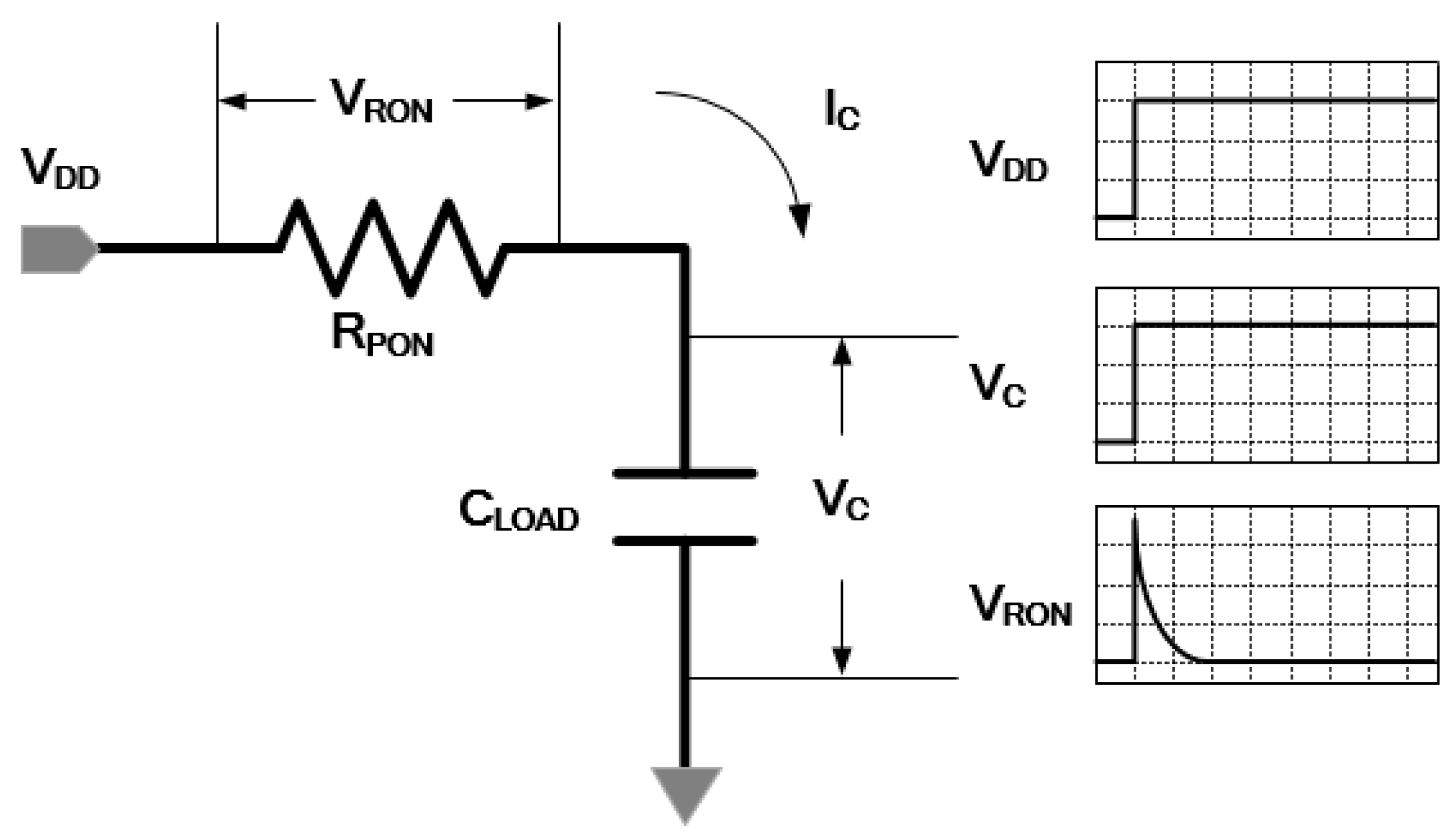
Figure 1 shows the voltage variation of source (V
DD), capacitance (V
C) and resistance (V
RON) respectively, in a conventional MOS pull-up network. A transistor is assumed to be a constant current source that can move the energy of CV
2 on the period of time. V
R represents the variation of the transistor channel voltage supplied from the drain. V
C represents the load voltage variation from the charged voltage. Rapid and large voltage variation at resistance cause a circuit to experience a large power dissipation due to the thermal loss [
5].
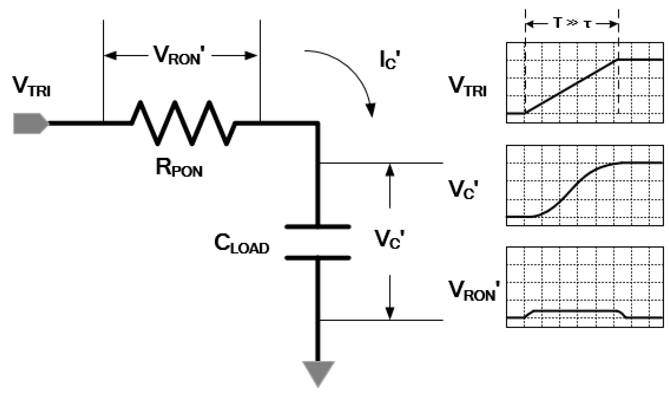
Figure 2 shows the voltage variation of source (V
TRI), capacitance (V
C’) and resistance (V
RON’) respectively, in an adiabatic MOS pull-up network. When a voltage source with a long time constant of τ, such as ramped voltage V
I, was applied to transistor through drain, there was a small voltage variation that shows a little power consumption in the transistor. Theoretically, if the time constant approaches infinity, the energy consumption of resistance converges to zero [
6].
Figure 1.
MOS pull-up network VRON energy consumption.
Figure 2.
Adiabatic pull-up network VRON’ energy consumption.
V
RON is the change of voltage on the channel resistance R
PON from step voltage source V
DD at pull-up network in
Figure 1 V
RON can be expressed as:
where I
C is the displacement current across the load capacitance voltage V
C. I
C can be obtained from:
Load capacitance voltage, V
C and pull-up path current, I
C(t) is calculated as:
Power dissipation at load capacitance can be calculated as V
C(t) × I
C(t). MOS R
ON power dissipation can be expressed as:
Therefore, total energy dissipation of pull-up path can be calculated as:
where total energy dissipation is equal to supply energy.
V
RON' is the change of voltage on the channel resistance R
PON' from the ramped voltage source V
TRI, with the delay time of τ, at pull-up network in
Figure 2. I
C' is the displacement current from load capacitance voltage V
C'. V
C' and I
C' are calculated as:
Therefore, the total energy consumption of adiabatic pull-up path can be expressed as:
where total energy dissipation is equals to supply energy.
When ramped voltage source VTRI with delay time of τ, is supplied to adiabatic circuit design, energy consumption, CV2/2 in conventional MOS RON resistance can be reduced to an amount that can be expressed as CVTRI2.
3. Current LED Controller Using Adiabatic Operation
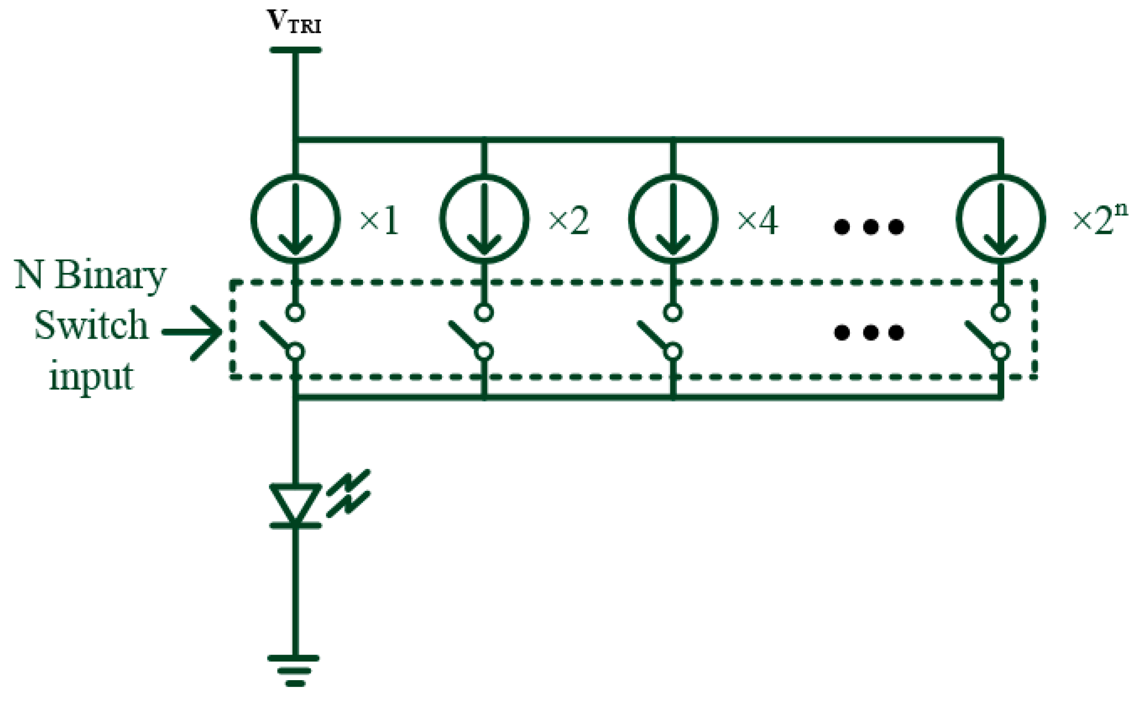
Figure 3 shows the proposed design of the adiabatic digital current LED controller. The current channel columns of the MOSFET are constituted according to the power of two for the LED drive current with an exponential function. Linearity of the output current can be achieved by the ON/OFF switch. The amount of the LED dimming can be determined in each binary switch current. Output current is determined with the LED specification. The current rating of the proposed design is determined with 25 mA by typical intermediate current of LED.
Figure 3.
Current Light Emitting Diode (LED) control design circuit using adiabatic operation.
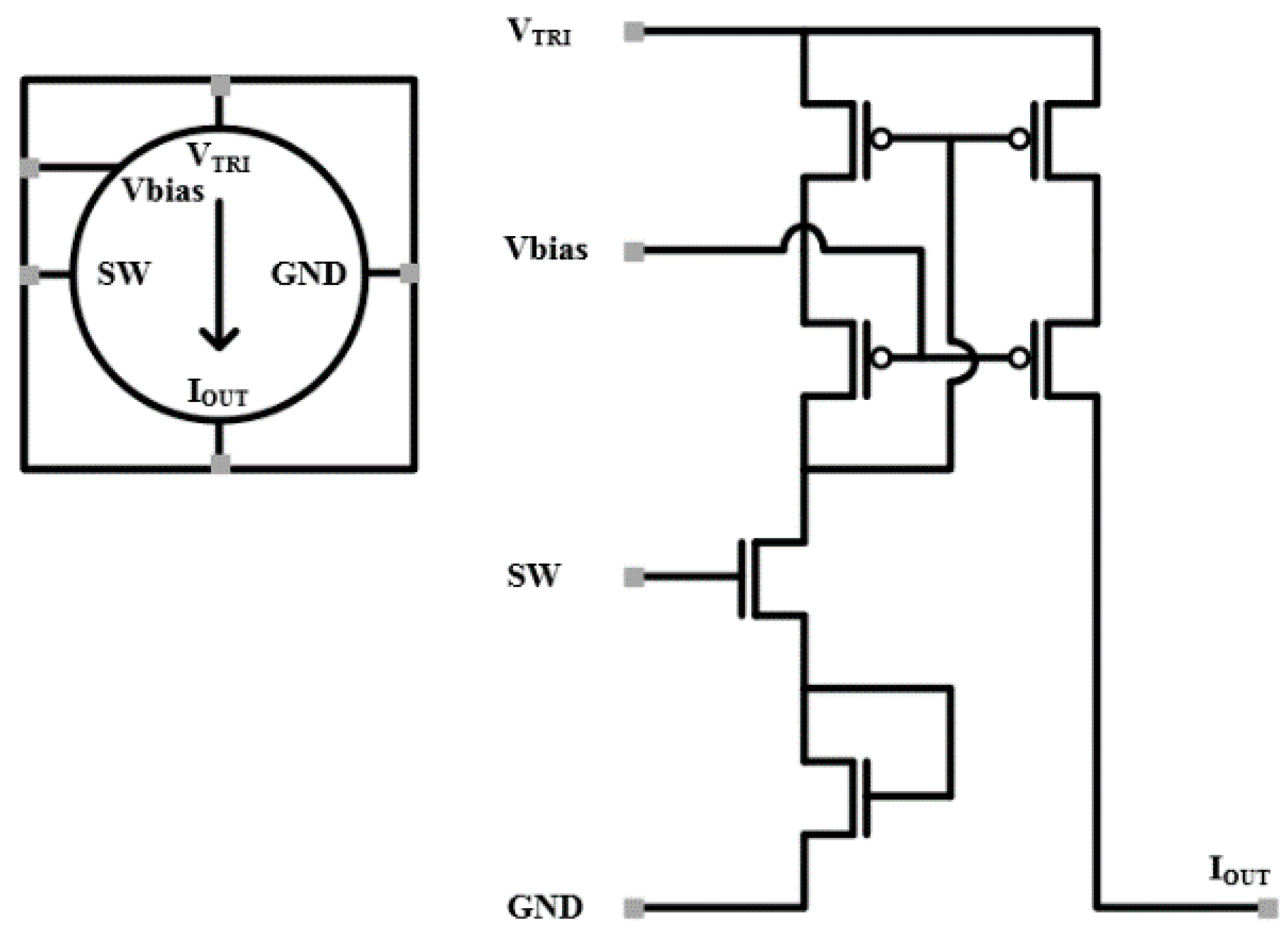
Figure 4 shows the basic circuit of the proposed LED controller with adiabatic operation. The basic circuit was designed with a high output impedance of two-stage PCH. It is a feature of LED that the current is determined with an exponential voltage change. A utilized MOS transistor is saturated when the switch is high. The LED’s utilized load is an equivalent circuit which is constituted with 100 Ω resistance in the condition of a typical voltage of 2.5 V with a current of 25 mA. The zener diode that is used for safe operation of the LED is represented with 1 nF capacitance.
Figure 4.
Basic circuit of LED controller with adiabatic operation.
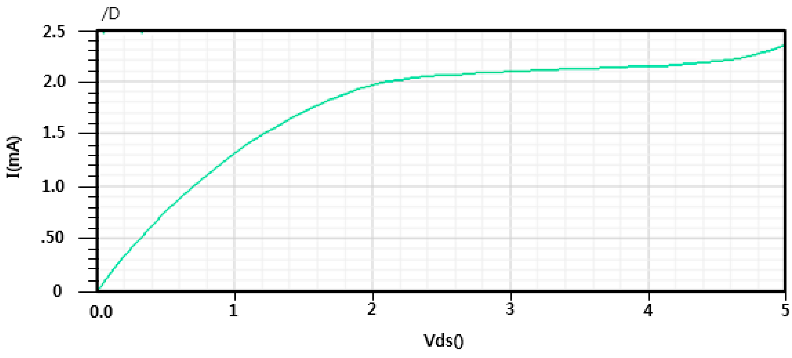
Figure 5 shows the I/V characteristic with 0.35 μm CMOS process technology by the Dong-Bu company.
Figure 5.
I/V characteristic of the used MOS transistor.
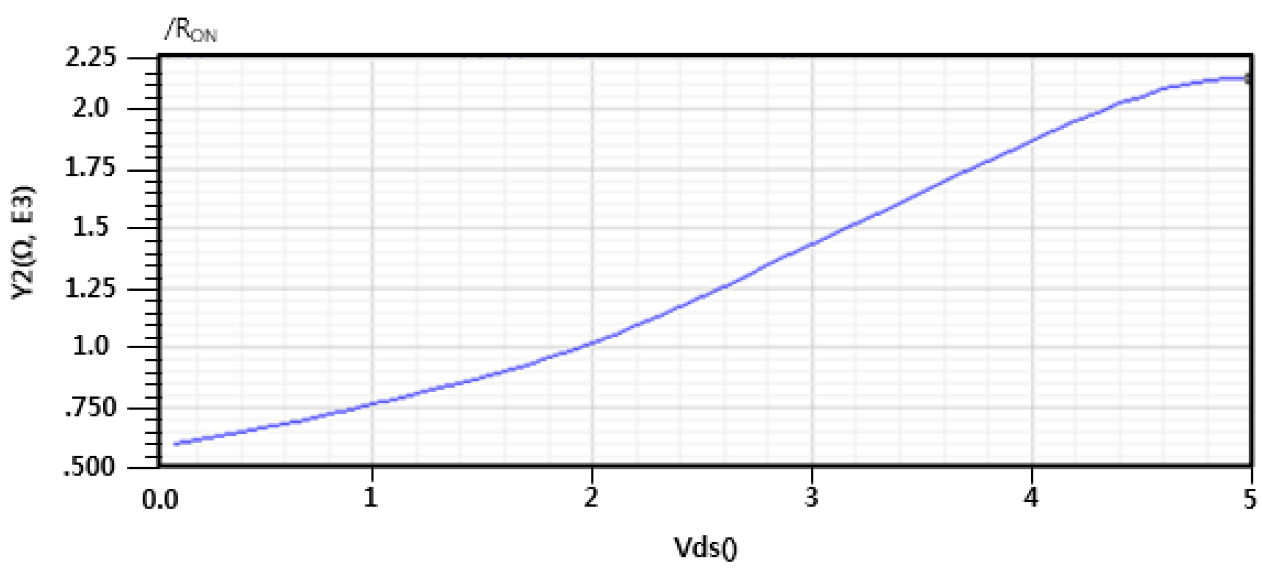
Figure 6 shows the characteristics of V
DS/I
DS = R
ON. The time constant is 2
−15 s in the condition of a constant V
DS = 5V, and the resistance of the MOS transistor is 2 mΩ. Load capacitance is 1 pF. Ramped V
DS is characterized with a cycle with 0.5–6 s and the time constant can be expressed as 0.25–6 s as a maximum value. If V
DS is not a peak value, V
DS is always smaller than 5 V; therefore, the time constant of the ramped voltage of V
DS is calculated as 0.25
−6 s × 63% = 0.15
−6 s.
Figure 6.
RON characteristic of the used MOS transistor.
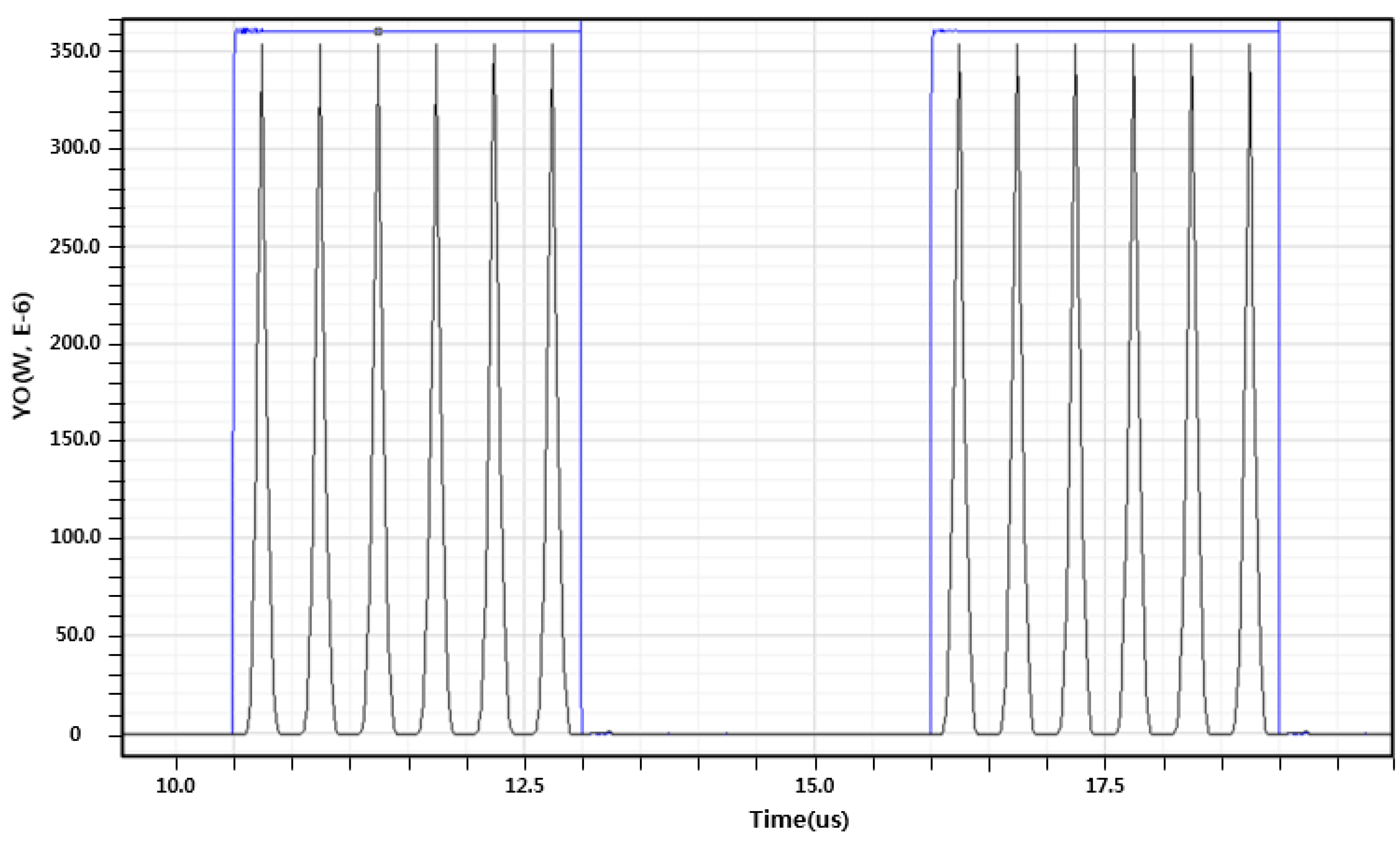
Figure 7 shows the power dissipation in comparison with the constant V
DD and ramped V
DD operation of the designed circuit. The energy dissipation of the constant V
DD operation in the period time of 0~100 μs is 16 μW. Energy dissipation of the ramped V
DD operation is 3 μW. The basic circuit with adiabatic operation in comparison with conventional operation shows an energy reduction of 82%.
Figure 7.
Power consumption comparison between constant VDD operation and ramped VDD.
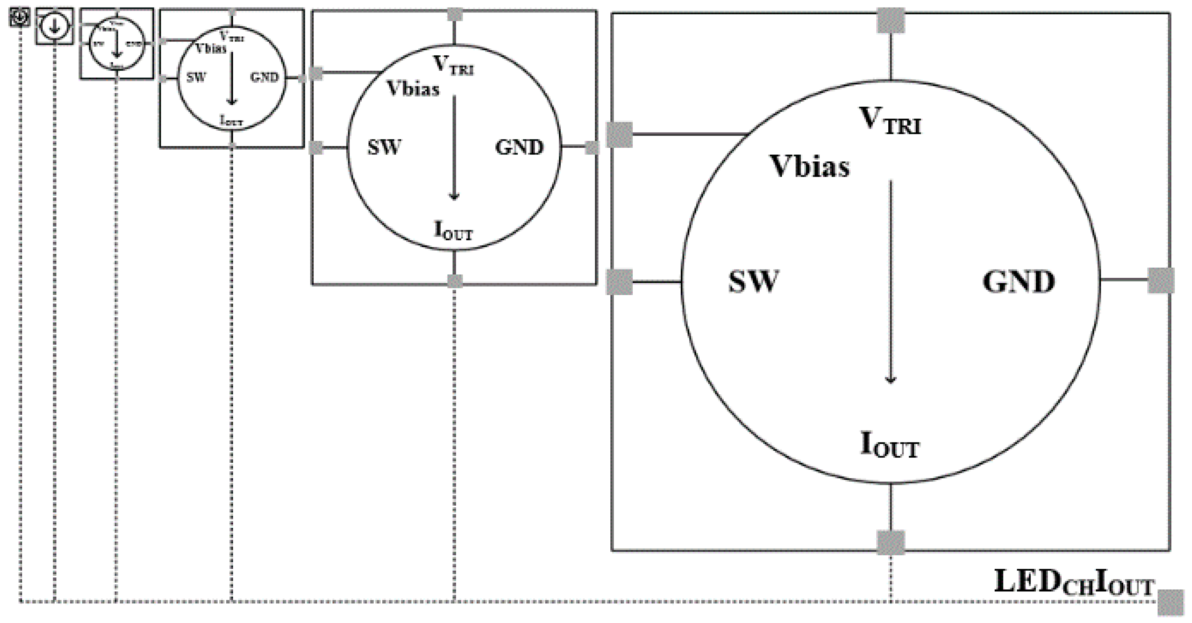
Figure 8 shows the LED controller structure that has 6-channel switches to the 63 basic circuits. Output current, LED
CHI
OUT shows the linear characteristic.
Figure 8.
6-bits current LED controller structure using adiabatic operation.
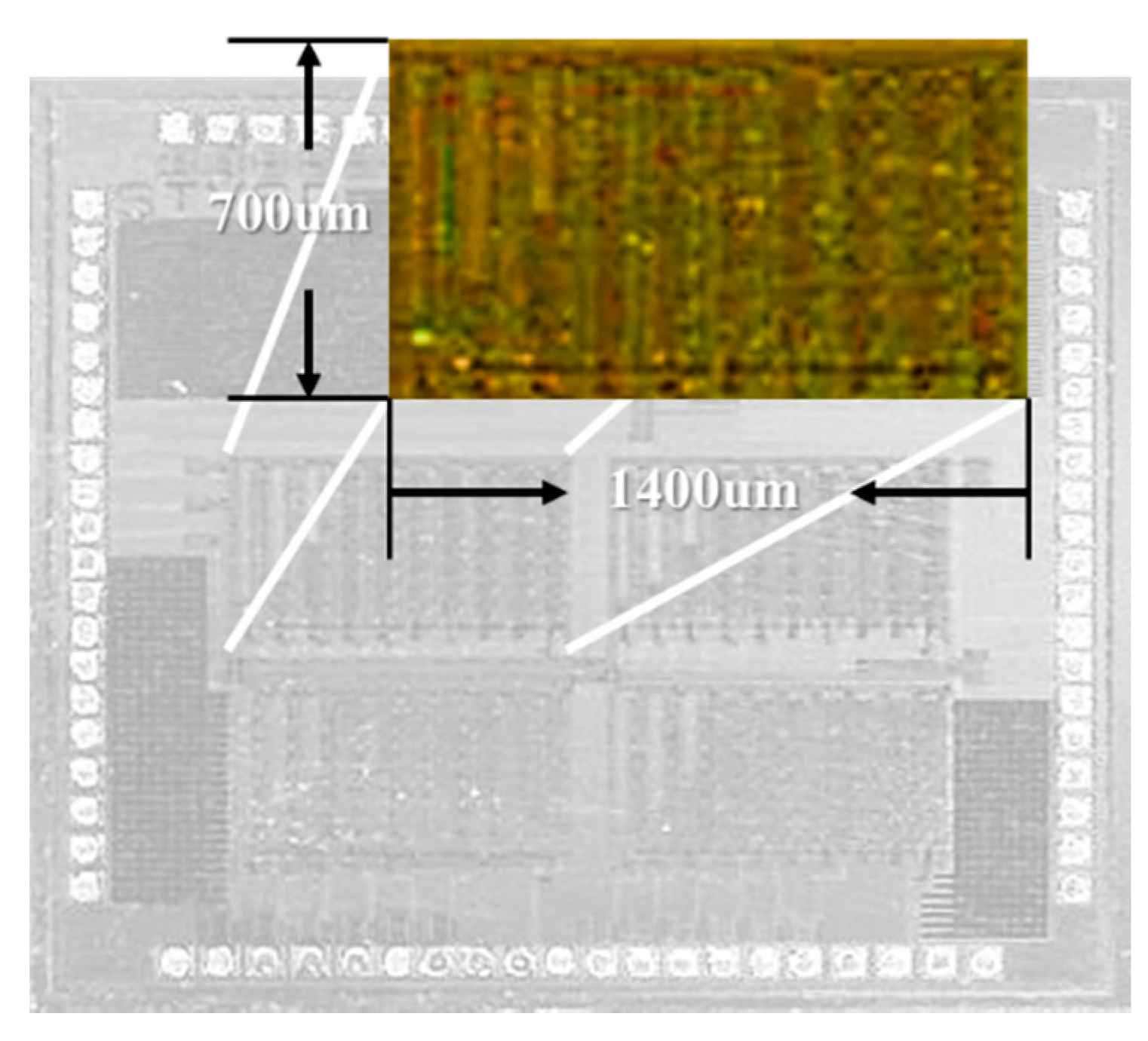
Figure 9 shows the photograph of the designed LED controller. The LED 4-channels with adiabatic operation were implemented with 0.35 μm CMOS process technology by the Dong-Bu company and the size was 1400 μm × 700 μm.
Figure 9.
Photograph of LED controller.
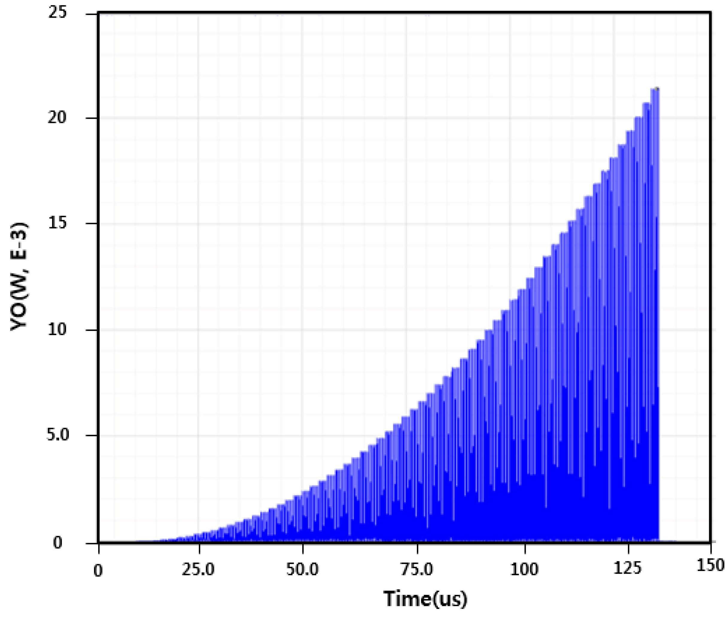
Figure 10 shows the power consumption of the proposed adiabatic design with a constant V
DD. The energy dissipation of the conventional operation is observed with 1.13 μJ in a time period of 150 μs from the simulation result.
Figure 10.
Power consumption of conventional 6-bits LED controller.
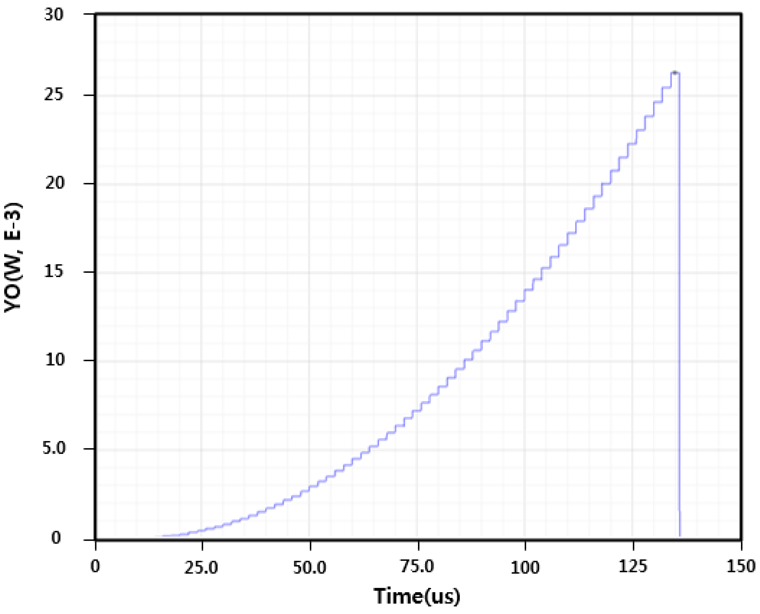
Figure 11 shows the power consumption of the proposed adiabatic design with V
TRI. The energy dissipation of adiabatic operation is evaluated with 0.21 μJ in the period time of 150 μs. From the simulation result, the power consumption of the proposed LED controller using adiabatic operation was reduced to about 87% in comparison with the conventional operation with a constant V
DD.
Figure 11.
Power consumption of adiabatic 6-bits LED controller.
The specific heat of Silicon material as the main component of an LED system is 0.713~0.8 J/gºC [
7]. When an LED channel is used in same condition of proposed design, temperature of the LED controller can be limited to 0.26/1.41 μºC, 18%.
