Lightweight Design and Welding Manufacturing of a Hydrogen Fuel Cell Powered Car’s Chassis
by
 , and
, and
Evangelos Ch. Tsirogiannis
1,* ,
,
Gerasimos I. Siasos
2,
Georgios E. Stavroulakis
3 and
and
Sofoklis S. Makridis
4
1
School of Mechanical Engineering, National Technical University of Athens, GR15780 Athens, Greece
2
Department of Mechanical Engineering, Coventry University, Priory Street, Coventry CV1 5FB, UK
3
School of Production Engineering and Management, Technical University of Crete, GR73100 Chania, Greece
4
Department of Environmental and Natural Resources Management, University of Patras, GR30100 Agrinio, Greece
*
Author to whom correspondence should be addressed.
Challenges 2018, 9(1), 25; https://doi.org/10.3390/challe9010025
Submission received: 13 April 2018
/
Revised: 23 May 2018
/
Accepted: 24 May 2018
/
Published: 27 May 2018
Abstract
:The development of the chassis for the hydrogen fuel cell powered car has been involved in the designing and manufacturing aspects, while taking into consideration the mass, strength, stiffness, centre of gravity (COG), and manufacturing cost requirements. Towards this direction, a chassis design is proposed employing a space frame structure and constructed by an aluminium alloy with great strength. The structural design has been derived through the lightweight engineering approaches in conjunction with the part consolidation, Design for Assembly (DFA) and Design for Manufacture methods. Moreover, it has been performed in compliance with the safety regulations of the Shell Eco Marathon racing competition. The material’s principal characteristics are the great strength, the low mass, as well as the great workability, machinability, and weldability. Following the national and global environmental issues, the recyclable characteristics of the aluminium alloy are an extra asset. Furthermore, the existence of aluminium alloy manufacturers around the fabricating area provides low cost supply and fast delivery benefits. The integration of the fuel cell powered vehicle is obtained through the designing and the manufacturing processes of the chassis and the parts fitted on the chassis. The manufacturing procedures are described thoroughly; mainly consisting of the cutting and welding processes and the assembling of the parts that are fitted on the chassis. Additionally, the proper welding parameters for the custom chassis design are investigated and are selected after deductive reasoning. The quality control of the weld joints is conducted by non-destructive methods (NDT) ensuring the required structural properties of the welds. A combination of the selected material, the specific type of the chassis, and the manufacturing processes lead to construction simplicity in a low manufacturing cost by using the existing laboratory equipment. Furthermore, the designing and manufacturing parameters lead to a stiff with a low centre of gravity, and the most lightweight chassis of the urban concept category at the Shell Eco Marathon race.
Keywords:
chassis; lightweight; welding; cutting; part consolidation; DFMA; DFA; manufacturing; CAD; electric car1. Introduction
Nowadays, automotive manufacturers are focused on the improvement of a car’s efficiency. Particularly, the main objective of the car development is the minimization of its energy consumption and its autonomy maximization. At the same time, countries seek to address future energy requirements and reduce the emissions of pollutants. Consequently, alternative power cars such as electric and fuel cell powered are investigated not only to maximize the cars’ efficiency, but also to meet the emission standards. Thus, since cars with internal combustion (IC) engine are not efficient enough, as well as that they meet low emissions standards; electric and fuel cell powered cars are becoming a promising solution for the near future. Actually, many automotive manufacturers have already begun the production of electric cars. Specifically, China has become the world’s largest electric vehicles market [1].
Undoubtedly, the improvement of car’s efficiency is achieved not only by the proper selection of power, but also by the production of lightweight and stiff car’s structures. In the present work, the car’s power is provided by a hydrogen fuel cell. The main goal is the design and production of a lightweight structure suitable for the fuel cell powered car, in a low production cost. Τhe current work has been revealed through the development of previous works [2,3]. It is worth noting that the chassis is particular designed for the needs of the Shell Eco Marathon racing competition [4]. This implies that it should be designed according to the regulations of Shell Eco Marathon to ensure the driver’s safety during the race [5,6].
The electric vehicle (EV) is one-seated, four wheel car. The body shell is constructed by 1 mm thickness carbon-fiber. The energy system of the car is consisted of a brushless electric motor with 4 Nm max motor torque and 4000 RPM max motor rotational frequency, powered from a 1.2 KW H2 fuel cell. The fuel cell uses a hydrogen 200 bar bottle as a fuel tank. The achieved autonomy is around 70 km/kwh and the CO2 emissions are 0 g. These specifications are adopted by [2,3,7].
The selection of the suitable chassis type for a fuel cell powered car takes into account several factors. In the current study, the most critical are the weight, the strength, the stiffness, the materials, the production difficulty, the production time, and the production cost. The characteristics of each chassis structure have been provided by literature [8,9], and especially for electric cars by [10]. In the current application, the main selection criteria for the proper chassis type are the construction simplicity, the use of easy manufacturing processes, and the low manufacturing cost, which is subject to enough strength and stiffness. Consequently, the space-frame construction has been chosen due to the fact that it combines the aforementioned characteristics. Examples of electric cars with space frame chassis are found in literature for racing car [11] and for autonomous guided vehicle [12]. In addition, chassis designs for fuel cell powered cars suitable for Shell Eco Marathon have developed in previous works using carbon-fiber monocoque type [13] and carbon-fiber monocoque type reinforced with honeycomb [14].
Τhe strength of the space frame is provided by tubes. The design principle is based on the construction of a structure where the tubes are mainly loaded in their strongest direction, in tension and compression loads. Although the strength of the chassis should be considered, however, it should be combined with lightweight, low centre of gravity (in z axis), manufacturing and assembly simplicity, low manufacturing cost, and a short manufacturing time. Thus, the chassis should be designed respecting the part consolidation method and the design for assembly method, as described in literature [15]. Furthermore, approaches for lightweight engineering are referred in [16,17] and were taken into consideration for our study. Lightweight strategies have been already developed for industrial robot arms [18] and for car structures [19,20,21,22]. Moreover, the centre of gravity (COG) of the chassis structure as well as the car should remain low with the driver on seat. The car’s centre of gravity can be calculated with the use of literature [23,24,25,26,27].
Generally, the strength, the mass, the workability, machinability, and weldability are the main selection technical characteristics of the chassis material. Also, the recycling characteristics have been considered for environmental protection reasons. For the selection of the proper material, the material selection methodologies that were applied are described in literature [28,29]. Furthermore, the low supply cost and the low supply time of the received material are of utmost significance. Thus, the material manufacturer should be located near the chassis fabricating area, which is located in Greece. After extensive research, it was found out that the underground of Greece has great amounts of aluminium deposits, as well as many of the national aluminium manufacturers, have great experience in automotive engineering aluminium alloys since they are suppliers in many automotive industries. Consequently, the 6082-T6 aluminium alloy material is selected for the low supply cost and time in conjunction with the great technical and recycling characteristics. Meanwhile, the low supply cost and time could be a major advantage for a pertinent aluminium chassis production in Greece when compared to other automotive industries that receive the aluminium from other countries. An example of an aluminium space frame chassis is presented in this work [30].
Τhe manufacturing of the space frame is complex and it sometimes it entails risk because of the many tubes that need to be cut and welded together accurately. Nevertheless, the production of the whole structure is using easy manufacturing processes. The theory for the machining operations is explained in literature [31] and for the welding in literature [32]. The materials and their behaviour during welding are explained in this work [33]. Particularly, the characteristics of 6082 and especially its performance in welding are described in literature [34]. The welding parameters have been chosen according to the literature [32] and the study on 6082 aluminium alloys [34]. Finally, the fundamentals for non-destructive testing are described in the bibliography [35], and for quality control of the welding processes in [36,37].
The novelty of this work is the achievement of the lightest chassis of the urban concept category at the Shell Eco Marathon race, as well as the extra low centre of gravity. When compared to other similar projects, the detailed description of the manufacturing processes and especially the chosen welding parameters for a custom chassis structure is an asset.
2. Results and Discussion
2.1. Design of the Electric Car’s Chassis
2.1.1. Design for Space Frame Truss Structures
Traditionally, the space frame is usually consisted of many tubes jointed together. It is designed on the principle that the tubes are mainly loaded in their strongest direction. Thus, the structure is designed properly, so as the tubes to be loaded especially in tension and compression loads, therefore the tubes are small and light [9].
Additionally, one of the major designing criteria for the chassis is the structural stiffness. Hence, bracing members are placed to prevent twist and to offer stiffness. The aim is to build a chassis where every single member has a bracing attachment, and it has no twisting forces acting on it, just compression and tension. With this principle the designer is trying to remove torsion, shear, bending and other kind of forces acting on chassis members to make them smaller, thinner and lighter at the same time as building a stiffer overall structure. Obviously, not every gap between tubes can be braced. The designer must take into consideration that the chassis has enough space for the driver and for the mechanical and electrical parts [3,8,38].
The materials and the principles that are used in the space frame are simple, and as a result a stiff and light structure can be assembled without any special techniques. For that reason, the space-frame chassis remains a very popular way of building vehicles with very good performance characteristics.
2.1.2. Lightweight and Part Consolidation Methods
During the designing process of the space frame, lightweight techniques have been taken into consideration [16,17]. Furthermore, the chassis has been designed according to the part consolidation method. Part consolidation is an effective way to reduce part count and the consequential process time and cost. This method has been intensively studied in Design for X (DFX), such as Design for Assembly (DFA), and Design for Manufacture and Assembly (DFMA). Specifically, in the Design for Assembly (DFA) method, the main purpose is to reduce assembly time, cost, and difficulties [15].
Consequently, the objective of the electric car’s chassis design is to minimize the number of tubes and to eliminate the weld joints. Both considerations are implying fewer assembly operations, which is the primary driver to reduce the assembly time and costs. Also, another objective of the structural design is the weight reduction, as mentioned previously.
2.1.3. Chassis Design
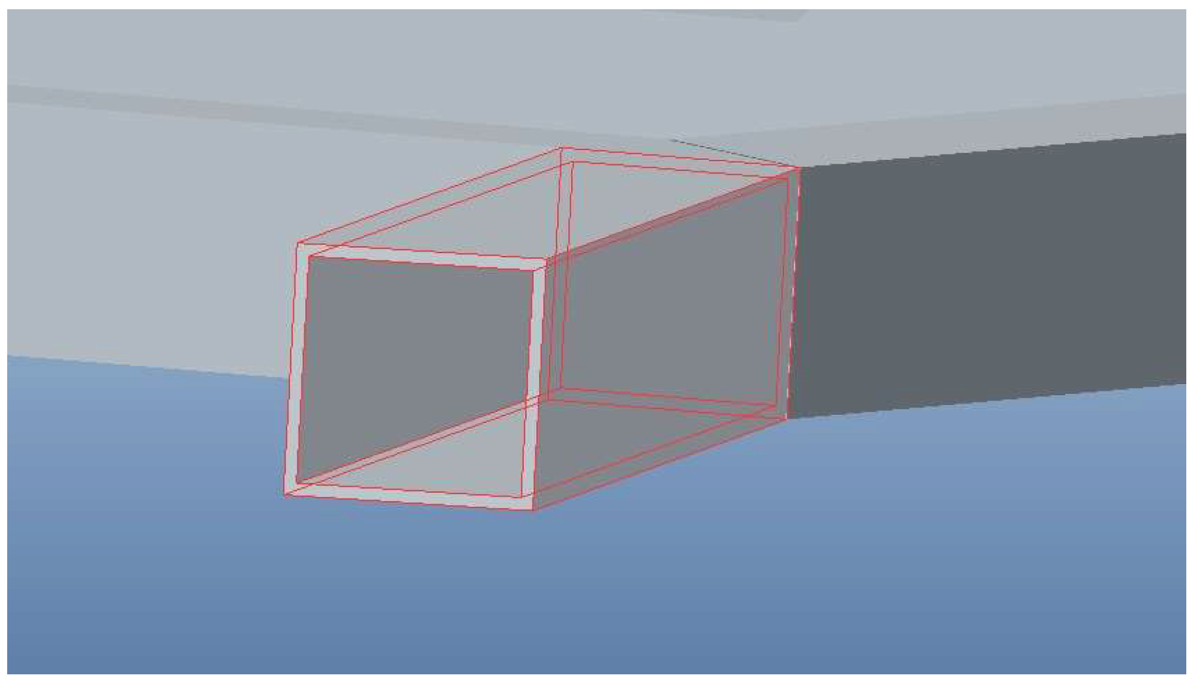
The tubes have been selected to be with square section so as to be cut and welded more easily, resulting in an uncomplicated manufacturing and assembly construction. In particular, they are (30 × 30) mm hollow sections with 1.5 mm wall thickness, as demonstrated in Figure 1.
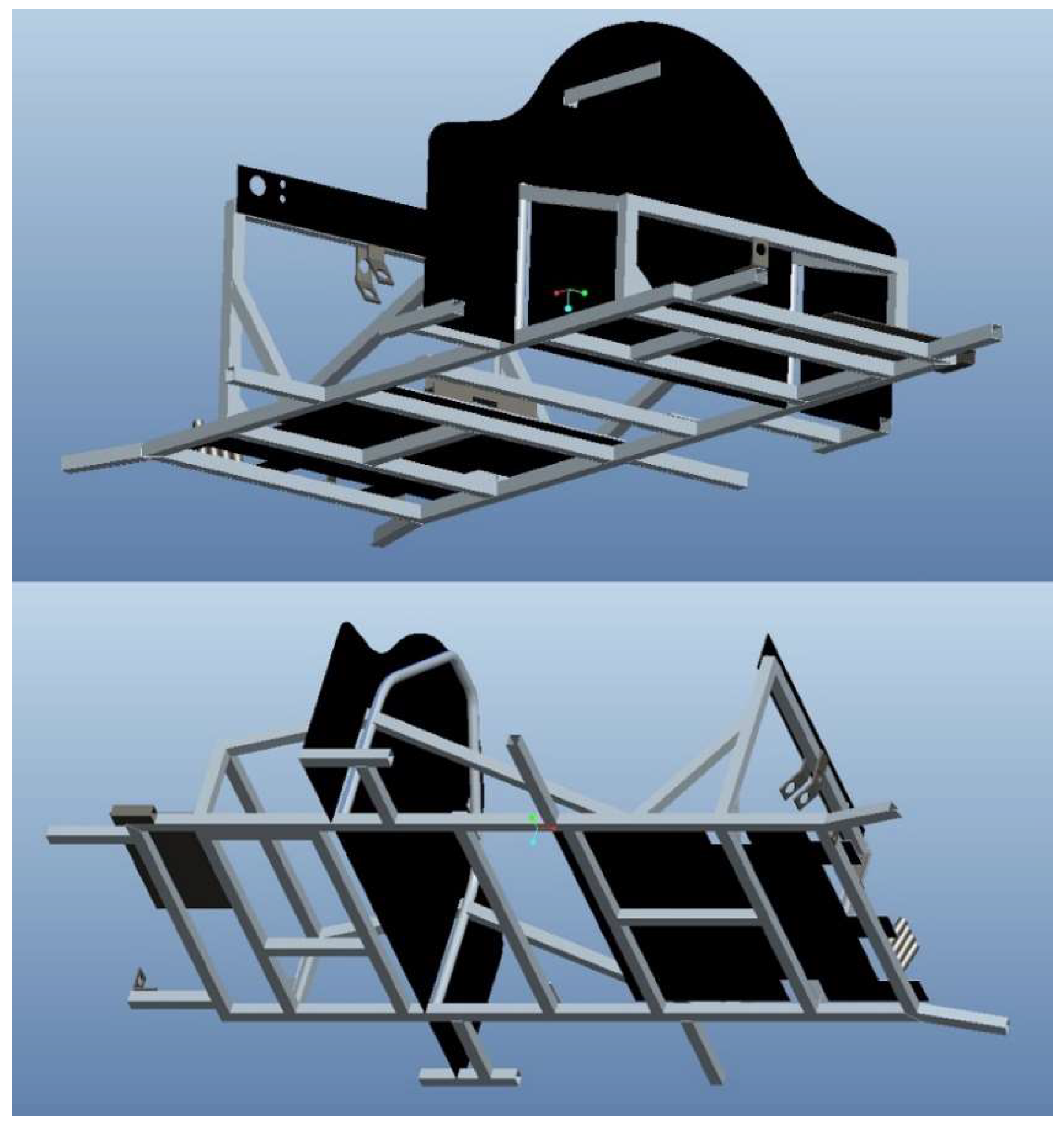
Accordingly, the chassis structure is consisted of thirty-two tubes. These tubes are assembled together properly, and therefore, the space frame chassis design is created, as shown in Figure 2 and Figure 3 [6,39].
Worth mentioning that the chassis design also includes several bases and sockets, especially for the accelerator, the brake pedal, the steering system, the electric motor, and the driver’s seat. Moreover, it includes a floor, a dashboard, and a bulkhead.
2.1.4. Design of the Parts Fited on the Chassis
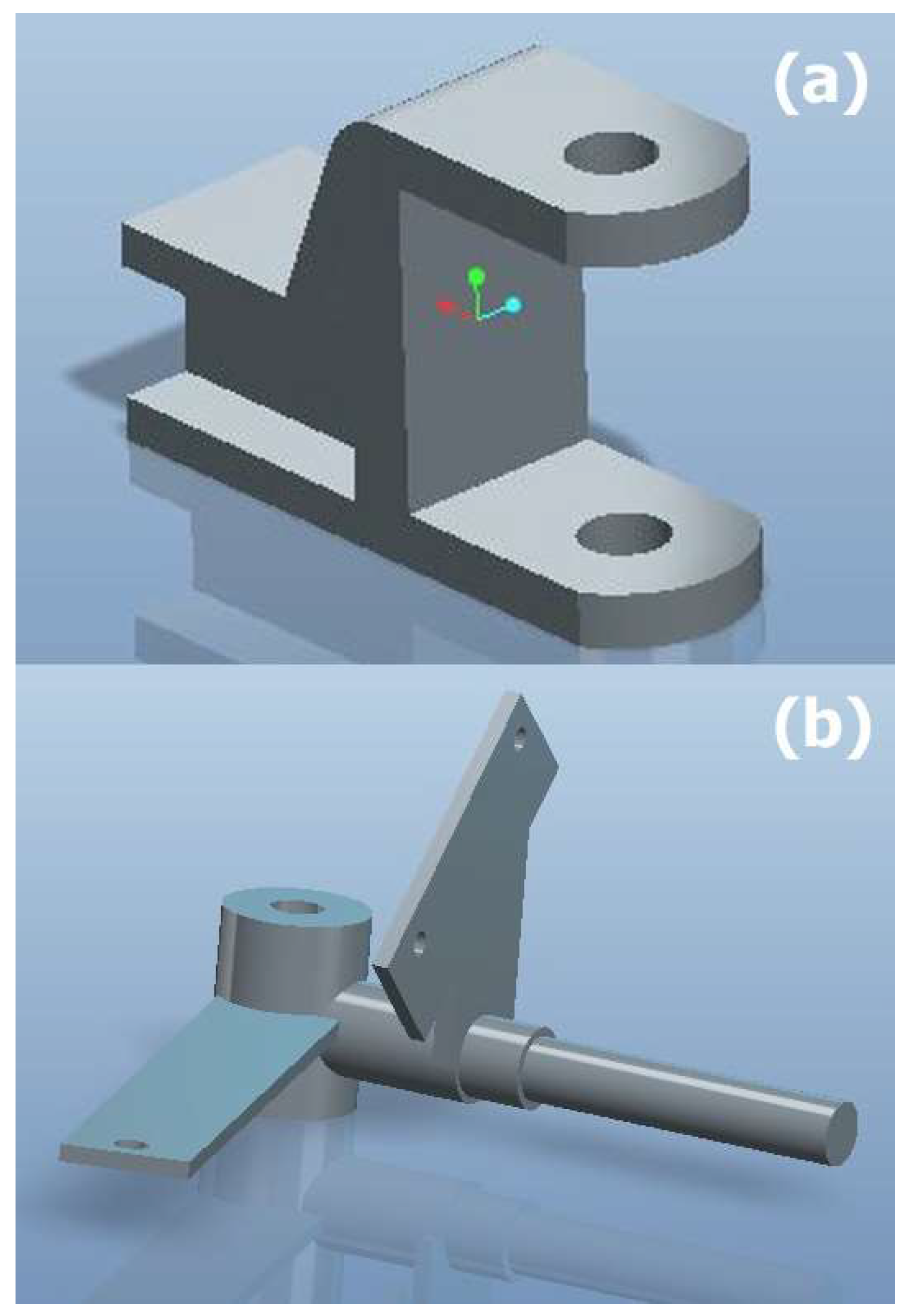
Additionally, the chassis has been jointed with two front semi-axle kits and two rear semi-axle kits. The front semi-axle kit consists of a front spindle base and a front spindle. The three-dimensional designs of the front spindle base, the front spindle, and the rear semi-axle kit are illustrated in Figure 4 and Figure 5.
It is worth to notice that the body of the electric car has been also designed, studied, and manufactured; however, it is outside the scope of this work.
2.1.5. Safety Considerations for the Electric Car’s Chassis
During the designing process, the safety of the electric car’s chassis has been considered. The safety of the driver should be ensured at all times. In fact, many rules should be followed in order to design a safe chassis, and in general, a safe car. In the current study, the space frame has been designed according to the safety regulation of the Shell Eco Marathon competition [4]. In particular, the chassis has been designed wide and long enough to protect the drive’s body. Moreover, specific dimensional demands have been respected to allow for quick driver egress in the case of accidents or fire. Furthermore, the existence of a roll bar was indispensable. Specifically, the roll bar withstands at least 700 N (applied in all directions). Also, it extends 5 cm around driver’s helmet. In addition, a bulkhead has effectively sealed the driver’s compartment from the propulsion and fuel system. Essentially, the electric engine, the fuel cell, the fuel tank, the batteries, the hydrogen cylinders, the super capacitors, etc. have been placed outside the drive’s compartment behind the bulk head [5,14,40].
Nonetheless, the aforementioned safety rules concern the chassis design. Obviously, there are several extra safety criteria that have been applied to the electric car, such as vehicle’s headlamps, reflectors, lights and signals, mirrors, brakes system, steering system, seatbelt, and so on.
2.2. Material Selection and Properties
Undoubtedly, aluminium is lighter than most of the metals. Moreover, alloys that are based on aluminium may have better stiffness-to-weight and strength-to-weight ratios than steel. Therefore, the light weight is a crucial advantage of aluminium alloys [41].
In the current automotive application, the 6082-T6 aluminium alloy type has been selected as the construction material. In general, 6082-T6 is highly applied for cars [42]. The major selection criteria of this alloy were the great strength, the low mass as well as the great workability, machinability, and weldability. The stiffness, the fatigue strength, the corrosion resistence, and the durability characteristics have been also taken into account [33]. When considering the environmental protection the current material has been selected for its recyclable characteristics, as well. Finally, the low supply cost and the low supply time, which are provided by the national aluminium alloy manufacturers, have played a significant role [28].
The aluminium alloy 6082 belongs to 6000 series aluminium alloy and the most common tempers for 6082 aluminium are T6 (solution heat treated and artificially aged), O (Soft), T4 (solution heat treated and naturally aged to a substantially stable condition), and T651 (solution heat treated, stress relieved by stretching then artificially aged). The 6082-T6 is an alloy with very good strength and excellent corrosion resistance. The addition of a large amount of manganese controls the grain structure, which in turn, results in a stronger alloy. Specifically, it has the highest strength of the 6000 series alloys [42]. Furthermore, in terms of yield strength, 6082-T6 outperforms the common aluminium alloy types while maintaining the same mass. The elastic modulus is very good as well. Hence, the elastic deflections can be low [28,29].
In the following, the mechanical properties of the chosen materials will be determined. Initially, for the space frame chassis and thereupon for the parts that are fitted on the chassis.
The mechanical characteristics of the 6082-T6 aluminium alloy are presented in Table 2.
Also, the density of the aluminium alloy is 2.7 × 10⁻⁹ tonne/mm3 [43].
Concerning the parts fitted on the space frame chassis, in the front end structure, the spindle base has been made of Aluminium 6082-T6 and the spindle of AISI 9000 Series Steel. The rear end structure has been made of AISI 9000 Series Steel. The properties of the aluminium alloy were mentioned in Table 2 and the properties of the steel are presented in Table 3.
The density of the steel is 7.8 × 10⁻⁹ tonne/mm3 [43].
Mass and Centre of Gravity Calculation
Subsequently, the mass and the centre of gravity of the chassis, as well as the electric car have been determined The software Pro Engineer gives the result of the chassis mass as 10.85 kg. Therefore, the total vehicle’s weight is only 155.1 kg (including the driver on seat with a weight of 75 kg). Thereafter, the software Pro engineer shows us the centre of gravity depends on the point that is specified by the designer. This point has been positioned in the centre of the axis (0, 0, 0), assuming that the distance on the x axis has been measured from the imaginary line that crosses the front of the chassis. It has been also assumed that the distance of the y axis is measured by the line on the left of the chassis, and on the z axis by the line that crosses the bottom of the chassis. Hence, the centre of gravity (COG) of the chassis is positioned, as shown in Table 4.
Afterwards, the centre of gravity of the electric car will be calculated. The different centres of gravity (battery light, steering system, driver + seat, chassis, fuel cell, electric motor) are added up, and they form the main centre of gravity. The masses of the wheels have been omitted because they have no effect on finding the gravity centre [3,23,24,25,26,27]. The electric car’s centre of gravity is given by:
where represent the different centres of gravity (battery light, steering system, driver + seat, chassis, fuel cell, electric motor) which are added up, and W their weights.
Wt = W1 + W2 + W3 + W4 + W5 + W6
COGx = (Lx1W1 + Lx2W2 + Lx3W3 + Lx4W4 + Lx5W5 + Lx6W6)/Wt
COGy = (Ly1W1 + Ly2W2 + Ly3W3 + Ly4W4 + Ly5W5 + Ly6W6)/Wt
COGz = (Lz1W1 + Lz2W2 + Lz3W3 + Lz4W4 + Lz5W5 + Lz6W6)/Wt
After calculations, the centre of gravity (COG) of the electric car is determined in Table 5.
2.3. Manufacturing of the Electric Car
Space frames are using easy manufacturing techniques in conjunction with affordable cost. However, their construction needs attention, in terms of ensuring that all of the required bracing were cut rightly, as well as all the sections have been jointed together accurately. The following sections are focused on the description of the cutting and welding manufacturing stages, as well as the determination of the specific parameters that are involved in the welding technology.
2.3.1. Cutting Manufacturing of the Chassis’ Tubes
The cutting of the tubes has been obtained by the use of band saw machine. The thirty-two tubes have been cut accurately and in appropriate angles. It is noteworthy that this manufacturing technology is applicable for 6082-T6 aluminium alloy tubes because of their good workability and machinability. At the end of the cutting process, the cut edges have been cleaned with the use of the grinding machine [31].
2.3.2. Welding Manufacturing of the Chassis
As pronounced, the 6082 aluminium alloy has very good weldability. Nevertheless, welding pre-treatment has been required in order to ensure that the quality of the produced welds is sufficient. Particularly, the surfaces have been cleaned from oils or other liquids and the base material has been ensured that it does not have moisture due to the fact that aluminium alloy welding is susceptible to porous creation. Furthermore, a pre-heat temperature of 50 °C has been used. This sort of preheat is useful to drive off condensation and moisture [34]. Also, the electrodes have been properly stored so as to be dry. Otherwise, electrodes with moisture may lead to cracking or porosity. Bevelling was not required because the tubes are of thin thickness. Moreover, before the welding process, the tubes have been properly placed in a welding fixture table in order to be welded accurately.
The Tungsten Inert Gas (TIG) has been selected for the welding joining of the chassis tubes. Principally, the weldability of aluminium alloys with the use of Gas-Metal Arc Welding processes is very good [42]. Also, TIG welding method is commonly used to weld thin sections of non-ferrous metals in all of the welding positions. Due to the fact that it is relatively slow, it is highly maneuverable for welding tubing. It enables excellent penetration control and it can produce welds of excellent soundness. Weld termination craters can be filled easily as the current is tapered down by a foot pedal or electronic control. The economically weldable range of thickness for an aluminium alloy base material is 0.6 to 4.0 mm. Therefore, the TIG method is economically efficient for the current application since the thickness of the base material is 1.5 mm. Moreover, this process is usually selected for engineering applications that require small tolerances; hence, it is suitable for the space frame chassis construction. Additional benefits of the Tungsten Inert Gas method are the low heat input, the stable arc operation, the separate control of heat input and deposition efficiency, the good seam surface without splashes, and the gap bridging ability [32].
Actually, TIG is an arc welding process that uses a non-consumable tungsten electrode to produce the weld. The weld area and the electrode have been protected from oxidation and from other atmospheric contamination by an inert shielding gas. The welding units mainly consist of a welding power supply, a shielding gas bottle with pressure reducer and gas flow meter, a welding torch, and a welding clamp. The power supply is chosen with drooping characteristics, the wire feed is variable and the controlled variable is ΔU so as the welding current to be stable while the welder changes the welding length. The used welding torch is air-cooled (since the present application needs current lower than 250 A) and it includes the tungsten electrode and the gas nozzle.
TIG welding can be used with alternating current AC (~), or direct current DC (−), or direct current DC (+). In the most applications, it is used with DC (−). Negative polarity direct current entails that the electrode represents the negative side of the circuit and the electricity flows from the TIG torch to the base material. The emitted electrons provide too much heat to the base material, and therefore a deep penetration is obtained. In case of positive polarity direct current, the electrode represents the positive side of the circuit and the electricity flows from the base material to the TIG torch. The emitted electrons heat the electrode largely and therefore the electrode is consumed rapidly. The oxide surface area of the base material is destroyed. However, the base material is heated minimum, and therefore a shallow penetration is obtained. This implies that the use of DC (+) is not cost-effective. Several welding methods use this kind of polarity to weld thin plates with thick tungsten electrodes. Nevertheless, it is not usually preferred in aluminium TIG welding. Contrariwise, alternating current AC (~) offers the advantages of both the DC polarities. Particularly, during the positive electrode half of cycle it is provided an arc cleansing action to remove the surface oxide of the aluminium alloy base material and when the electrode is operated at negative polarity it is provided a penetrating arc to penetrate into the base material, while at the same time, the electrode that was heated previously, is cooled. Consequently, the chosen current for the welding of the aluminium alloy space frame was the alternating AC (~) one, for the aforementioned benefits that offers [32].
The quality and the efficiency of the TIG method depend largely on the type of tungsten electrode and the shape of the electrode end. The shape of the end of the electrode has an impact on the arc shape, and therefore in the shape of the heat flow. That affects the achieved penetration and, in general, the weld profile. The end of the electrode has been mainly defined by the current type and the polarity. Regarding the tungsten electrode types, they are composed of either pure tungsten or an alloy of tungsten and other rare-earth elements and oxides. In the present work, the selected type of the non-consumable electrode was the zirconiated tungsten electrode that contains a minimum of 99.10 percent tungsten and 0.15 to 0.40 percent zirconium. Zirconiated tungsten electrode is ideal for AC welding because it retains a balled tip and it has a high resistance to contamination. In addition, it produces an extremely stable arc and it resists tungsten spitting.
As far as the consumable electrode is concerned, a 4043 or a 5356 filler metal could be used. However, the 4043 filler alloy has been selected due to the fact that it provides lower crack sensitivity, less spatter, less smut, smoother surfaces, and it welds with improved appearance in comparison with 5356. The 4043 filler alloy is composed of an aluminium filler alloy with 5% silicon. The diameter of the filler metal is chosen 1.6 mm. Concerning the gas, the Argon has been used for the satisfying width and penetration in conjunction with its reduced cost, as compared to the cost of Helium and Helium-Argon mixtures in Europe. Also, the volumentric flow rate for Argon has been selected as 5 L/min. Furthermore, the welding current was chosen 50–70 A and the welding voltage 11 V. The joint types of the chassis structure were butt and corner welding joints, all of them welded with one pass [32,34].
The automation degree of the used TIG method was the manual welding, since the torque guidance, the filler metal feeding, and the handling of the base material were carried out manually. The manual welding has been selected because it enables low manufacturing cost for a low volume production. However, in the case of future mass production, the robotic TIG welding with mechanised torque guidance, mechanised filler metal feeding, and mechanised handling of the base material can offer less manufacturing cost, faster production, greater accuracy, and better quality [44]. In addition, Lean Manufacturing tools and techniques could be helpful in that case [45].
After the welding process, it is worth mentioning that the welds have been grinded for better appearance. Also, the obtained mechanical properties of the weld areas were sufficient, and therefore it was not needed annealing.
2.3.3. Cutting and Welding Manufacturing of the Parts Fitted on the Chassis
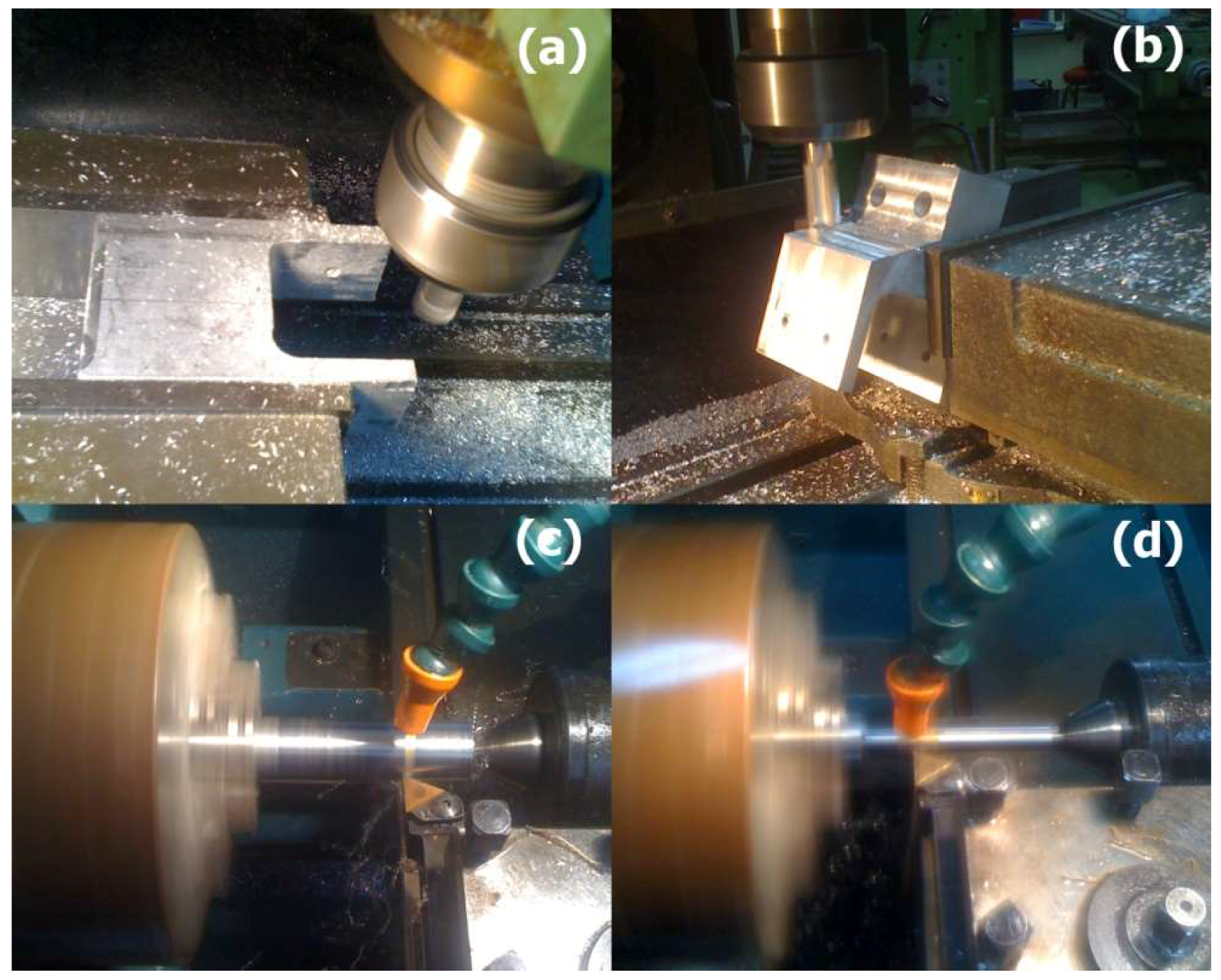
Thereafter, are described all of the necessary manufacturing processes regarding the parts fitted on the chassis. First of all, the front spindle base has been manufactured by milling machine. In the following, the two front spindles have been produced, with each of them consisting of two cylindrical parts and two plates. In particular, the cylindrical parts have been manufactured by turning machine and the plates by milling machine. The integration of each front spindle construction is obtained by the weld joining between the two cylindrical parts and the two plates. Thence, the rear semi-axle kits have been produced, with each of them consisting of one cylindrical part and one plate. The cylindrical parts have been manufactured by turning machine and the plates by milling machine. The integration of each rear semi-axle kit construction is obtained by the weld joining between one cylindrical part and one plate. Some steps from the production of the aforementioned structures are depicted in Figure 8.
2.3.4. Welding and Joining Manufacturing of the Electric Car
In the previous sections, the manufacturing of the chassis and the parts that are fitted on the chassis has been presented. Afterwards, the parts fitted on the chassis have been assembled with the chassis. Particularly, the two front spindle bases have been welded on the chassis and the two rear semi-axle kits have been jointed on the chassis with the use of bolts and flanges. In the following, the two front spindles have been jointed with the front spindle bases. Finally, the assembly of the whole car has been completed with several other parts that are mated on the chassis. Thus, the seat, the seatbelt, the bulkhead, the pedals, the floor, the dashboard, the wheels, the brakes, and the rest parts have also been placed. Τhe chassis, together with the rest parts of the electric car, are shown in Figure 9.
2.3.5. Quality Control
Generally, various types of flaw occur in the weld metal and the heat affected zones of welded joints. The different types of flaw could be crack, porosity, crater pipe, solid inclusions, incomplete fusion, incomplete root penetration, root concavity, undercut, overlap, incomplete filled groove, excess penetration, burn through, misalignment and angular misalignment, excessive cap, arc strike, deformations, and spatter. Moreover, grinding marks, chipping marks, and underflushing are also flaws that could be occurred by excessive grinding or other causes. Essentially, the majority of the TIG welding defects are tungsten inclusions, oxidation, and porosity. In particular, the aluminium welding is very susceptible to porous existence as well as large deformations [35,36].
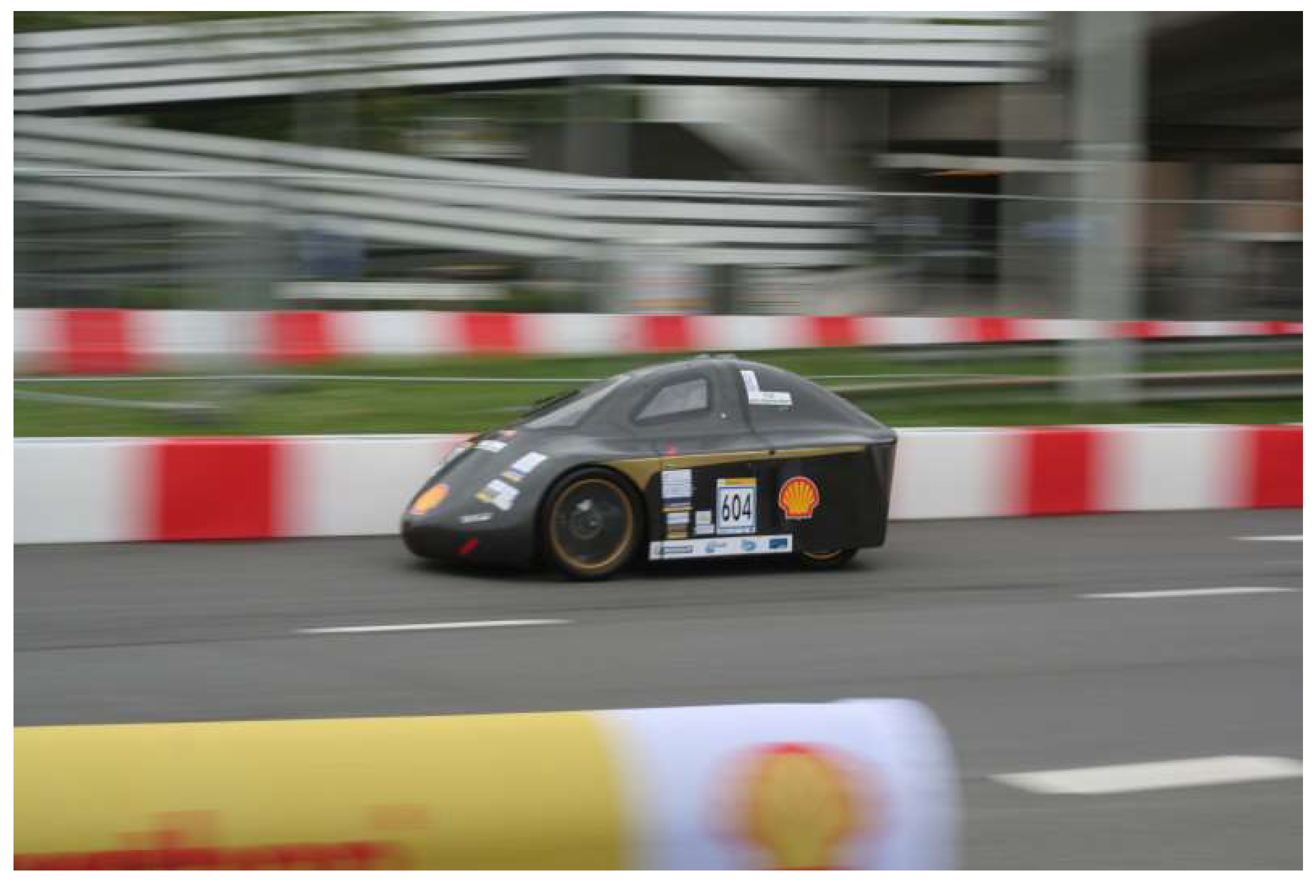
The quality of the welding joints has been examined so as to check if there are any defects. In fact, the existence of flaws is considered to be inevitable. Thus, it is necessary to determine the limits of tolerance in order to classify the flaws as defects or not [37]. For the detection and the evaluation of these flaws, Non-destructive testing (NDT) techniques, specifically the visual and ultrasonic, have been used. After the evaluation procedure, all of the flaws have been within the quality accepted limits. Finally, all of the welding joints pass the checks, which lead to run the car, as depicted in Figure 10.
3. Materials and Methods
The software Pro Engineer Wildfire 5 has been used for the three-dimensional design of the chassis and the parts that are fitted on the chassis, as well as for the calculation of the chassis centre of gravity. A band saw machine has been used for the cutting of the tubes. At the end of the cutting process, a grinding machine has been used for the cleaning of the cut edges. A TIG Machine has been used for the welding of the chassis. Before the welding process, a welding fixture table has been used to place the tubes properly. After the welding process, for the detection and the evaluation of flaws, the equipment of the visual and ultrasonic NDT techniques has been used.
4. Conclusions
Undoubtedly, the electric powered and fuel cell powered cars are the future of automobile industry. However, the processes from design to production of an electric car’s chassis, as well as the parameters that are involved in these processes are missing from literature. Contrariwise, this work thoroughly explains the design to production processes as well as it investigates the proper welding parameters for a custom chassis design.
The electric car’s chassis design has been performed respecting the part consolidation, the design for assembly (DFA), the design for manufacture and assembly (DFMA), and the lightweight engineering methods, while at the same time, complies with the Shell Eco Marathon rules. In the future, it is suggested the chassis members to be designed with more bracing attachments so as to make the tubes smaller and thinner. In parallel, the geometry of the tubes profile could be circle instead of square. Both of the changes could enable a lighter and stiffer structure. In this case, the manufacturing assembly complexity and the production time will be increased. Hence, a compromise between those parameters should be implemented according to the designing and manufacturing specifications.
The novelty of this publication is not only the achievement of the lightest chassis of the urban concept category at the Shell Eco Marathon competition, which only weighs 10.85 kg, but also the attainment of a chassis design with extra low centre of gravity.
Concluding, using easy manufacturing techniques and the know-how of experienced human resources, a Hellenic production line of automotive chassis could be supported. Furthermore, the great amounts of national aluminium deposits in combination with national aluminium alloy manufacturers with expertise in automotive engineering are assets towards this direction.
Author Contributions
E.Ch. Tsirogiannis contributed technical and research work; G.I. Siasos contributed manuscript preparation and discussion; G.E. Stavroulakis and S.S. Makridis contributed discussion and scientific supervision.
Acknowledgments
The authors are grateful to Dimitrios Stergiopoulos, teaching staff of Welding Greek Institute for his assistance in welding process. In addition, they would like to acknowledge Tuc Eco Racing (Tucer) research group. Furthermore, it is worth noting that performance design and numerical optimization are key issues in car industry especially for chassis design. Towards this direction, a new research work has been successfully completed through finite element analysis for the space frame chassis and it is going to be published in the near future.
Conflicts of Interest
The authors declare no conflict of interest.
References
- Chen, J. Prospects for Chinese electric vehicle technologies in 2016–2020: Ambition and rationality. Energy 2016, 120, 584–596. [Google Scholar]
- Tsirogiannis, E.C.; Stavroulakis, G.E.; Makridis, S.S. Design and Modelling Methodologies of an Efficient and Lightweight Carbon-fiber Reinforced Epoxy Monocoque Chassis, Suitable for an Electric Car. Mater. Sci. Eng. Adv. Res. 2017, 2, 5–12. [Google Scholar] [CrossRef]
- Tsirogiannis, E.C. Design of an Efficient and Lightweight Chassis, Suitable for an Electric Car; Technical University of Crete: Chania, Greece, 2015. [Google Scholar]
- Shell Eco Marathon. 2017. Available online: http://www.shell.com/eco-marathon (accessed on 29 July 2017).
- Shell Eco Marathon Official Rules. Available online: https://www.shell.com/energy-and-innovation/shell-ecomarathon/europe/for-europe-participants/_jcr_content/par/textimage.stream/1518517326978/43f16fc574ae1813fb480ab1ef51ac0928340661d149579b5e0fb47b10794ad8/shell-eco-marathon-europe-2018-rules-chapter-2.pdf (accessed on 29 July 2017).
- Pro/ENGINEER Wildfire Hands On Workshop. Available online: https://www.tu-chemnitz.de/mb/MHT/SAXSIM/pdf/archiv/HOW_2009_English.pdf (accessed on 29 July 2017).
- Tucer. Available online: www.tucer.tuc.gr (accessed on 25 July 2017).
- Brown, S.T.S.J.C.; Robertson, A.J. Motor Vehicle Structures; Butterworth-Heinemann: Oxford, UK, 2002. [Google Scholar]
- Gillespie, T.D. Fundamentals of Vehicle Dynamics; Society of Automotive Engineers, Inc.: Warrendale, PA, USA, 1992. [Google Scholar]
- Leitman, S.; Brant, B. Build Your Own Electric Vehicle, 2nd ed.; McGraw-Hill: New York, NY, USA, 2009. [Google Scholar]
- Bin Ab Razak, M.S.; bin Hasim, M.H.; bin Ngatiman, N.A. Design of Electric Vehicle Racing Car Chassis using Topology Optimization Method. MATEC Web Conf. 2017, 97, 01117. [Google Scholar] [CrossRef]
- Razak, M.S.A.; Rasit, K.H.M.; Nuri, N.R.M.; Rashid, M.Z. Structural design and analysis of autonomous guided vehicle (AGV) for parts supply. Proc. Mech. Eng. Res. Day 2016, 58–59. [Google Scholar] [CrossRef]
- Airale, A.; Torino, P.; Torino, P. Carbon fiber monocoque for a hydrogen prototype for low consumption challenge. Materwiss. Werksttech. 2011, 42, 386–392. [Google Scholar] [CrossRef]
- Carello, M.; Messana, A. IDRA pegasus: A fuel-cell prototype for 3000 km/L. Comput. Aided. Des. Appl. 2015, 12, 56–66. [Google Scholar] [CrossRef]
- Yang, S.; Zhao, Y.F. Additive manufacturing-enabled design theory and methodology: A critical review. Int. J. Adv. Manuf. Technol. 2015, 80, 327–342. [Google Scholar] [CrossRef]
- Grujicic, M.; Arakere, G.; Pisu, P.; Ayalew, B.; Seyr, N.; Erdmann, M.; Holzleitner, J. Application of topology, size and shape optimization methods in polymer metal hybrid structural lightweight engineering. Multidiscip. Model. Mat. Str. 2008, 4, 305–330. [Google Scholar] [CrossRef]
- Plucinsky, T. Lightweight Technology: Achieving the Right Ecological Balance; BMW Group: Woodcliff Lake, NJ, USA, 2003. [Google Scholar]
- Tsirogiannis, E.Ch. Reverse Engineering, Redesign and Topology Optimization for Additive Manufacturing of an Industrial Robot Arm Link; National Technical University of Athens: Athens, Greece, 2017. [Google Scholar]
- Raugei, M.; Morrey, D.; Hutchinson, A.; Winfield, P. A coherent life cycle assessment of a range of lightweighting strategies for compact vehicles. J. Clean. Prod. 2015, 108, 1168–1176. [Google Scholar] [CrossRef]
- Das, S. Life Cycle Energy and Environmental Assessment of Aluminium-Intensive Vehicle Design. SAE Int. J. Mater. Manf. 2014, 7, 588–595. [Google Scholar] [CrossRef]
- Mayyas, A.T.; Qattawi, A.; Mayyas, A.R.; Omar, M.A. Life cycle assessment-based selection for a sustainable lightweight body-in-white design. Energy 2012, 39, 412–425. [Google Scholar] [CrossRef]
- Kaluza, A.; Kleemann, S.; Frohlich, T.; Herrmann, C.; Vietor, T. Concurrent design & life cycle engineering in automotive lightweight component development. Cirp Conf. Comp. Mater. Parts Manuf. 2017, 66, 16–21. [Google Scholar]
- Wagtendonk, W.J. Principles of Helicopter Flight; Aviation Supplies & Academics Inc.: Newcastle, WA, USA, 1996. [Google Scholar]
- Seddon, J. Basic Helicopter Aerodynamics; BSP Professional Books: Oxford, UK, 1990. [Google Scholar]
- Prouty, R.W. Helicopter Performance Stability and Control; Krieger Publishing Company: Malabar, FL, USA, 1990. [Google Scholar]
- Measuring Center-of-Gravity Height on a Formula Car. Available online: http://www.jameshakewill.com/cg-height.pdf (accessed on 25 July 2017).
- Baraff, D. Physically Based Modeling-Rigid Body Simulation; ACM SIGGRAPH: New York, NY, USA, 2001. [Google Scholar]
- Maleque, M.A.; Salit, M.S. Materials Selection and Design; Springer: Signapore, 2013. [Google Scholar]
- Materials, E.; Reference, P.D. Engineering Materials and Processes—Desk Reference; Butterworth-Heinemann: Oxford, UK, 2009. [Google Scholar]
- Chung, Y.; Kang, H.; Cho, W. The Development of Lightweight Vehicle using Aluminum Space Frame Body. In Proceedings of the Seoul 2000 FISITA World Automotive Congress, Seoul, Korea, 12–15 June 2000. [Google Scholar]
- Groover, M.P. Fundamentals of Modern Manufacturing; John Wiley & Sons Inc.: Hoboken, NY, USA, 2010. [Google Scholar]
- Stergiopoulos, D. Welding Processes and Equipment; Welding Greek Institute (WGI): Elefsina, Greece, 2017. [Google Scholar]
- Diamantopoulos, K. Materials and Their Behaviour during Welding; Welding Greek Institute (WGI): Elefsina, Greece, 2017. [Google Scholar]
- Kah, P.; Hiltunen, E.; Martikainen, J. Investigation of Hot Cracking in the Welding of Aluminium Alloys (6005 & 6082). In Proceedings of the 63rd Annual Assembly & International Conference of the International Institute of Welding, Istanbul, Turkey, 11–17 July 2010; pp. 373–380. [Google Scholar]
- Raj, B.; Jayakumar, T.; Thavasimuthu, M. Practical Non-destructive Testing; Woodhead Publishing: Sawston, UK, 2002. [Google Scholar]
- Alevizakis, V. Fabrication, Applications Engineering; Welding Greek Institute (WGI): Elefsina, Greece, 2017. [Google Scholar]
- Miki, C. Discontinuities, imperfections and defects in welded joints and their effects on joint performance. Weld. Int. 1993, 7, 5–8. [Google Scholar] [CrossRef]
- Krenk, S.; Høgsberg, J. Statics and Mechanics of Structures; Springer: Dordrecht, The Netherlands, 2013. [Google Scholar]
- Lee, J.; Gu, N.; Jupp, J.; Sherratt, S. Evaluating Creativity in Parametric Design Processes and Products: A Pilot Study. In Design Computing and Cognition ‘12; Gero, J.S., Ed.; Springer: Dordrecht, The Netherlands, 2014. [Google Scholar]
- Van Kerkhoven, J.D.G. Design of a Formula Student Race Car Chassis; Technische Universiteit Eindhoven: Eindhoven, The Netherlands, 2008. [Google Scholar]
- Hull, D.; Clyne, T. An Introduction to Composite Materials (Cambridge Solid State Science Series); Cambridge University Press: Cambridge, UK, 1996. [Google Scholar]
- Aalco. Available online: www.aalco.co.uk (accessed on 22 June 2017).
- Material Property Data. Available online: http://www.matweb.com (accessed on 20 June 2017).
- Siciliano, B.; Sciavicco, L.; Villani, L.; Oriolo, G. Robotics: Modelling, Planning and Control; Springer: London, UK, 2009. [Google Scholar]
- Siasos, G.I.; Skondras, G.I.; Gkanas, E.; Hrissagis, K.; Makridis, S.S. The Benefits of Lean through an Analysis and Improvement of an Existing Production Line. Mater. Sci. Eng. Adv. Res. 2017, 2, 15–24. [Google Scholar] [CrossRef]
Figure 1.
Square hollow sections.


Figure 5.
Rear semi-axle kit (Note: The two flanges that are shown on the left of the semi-axle kit are used for the bolt connection between the rear semi-axle kit and the chassis) [3,7].
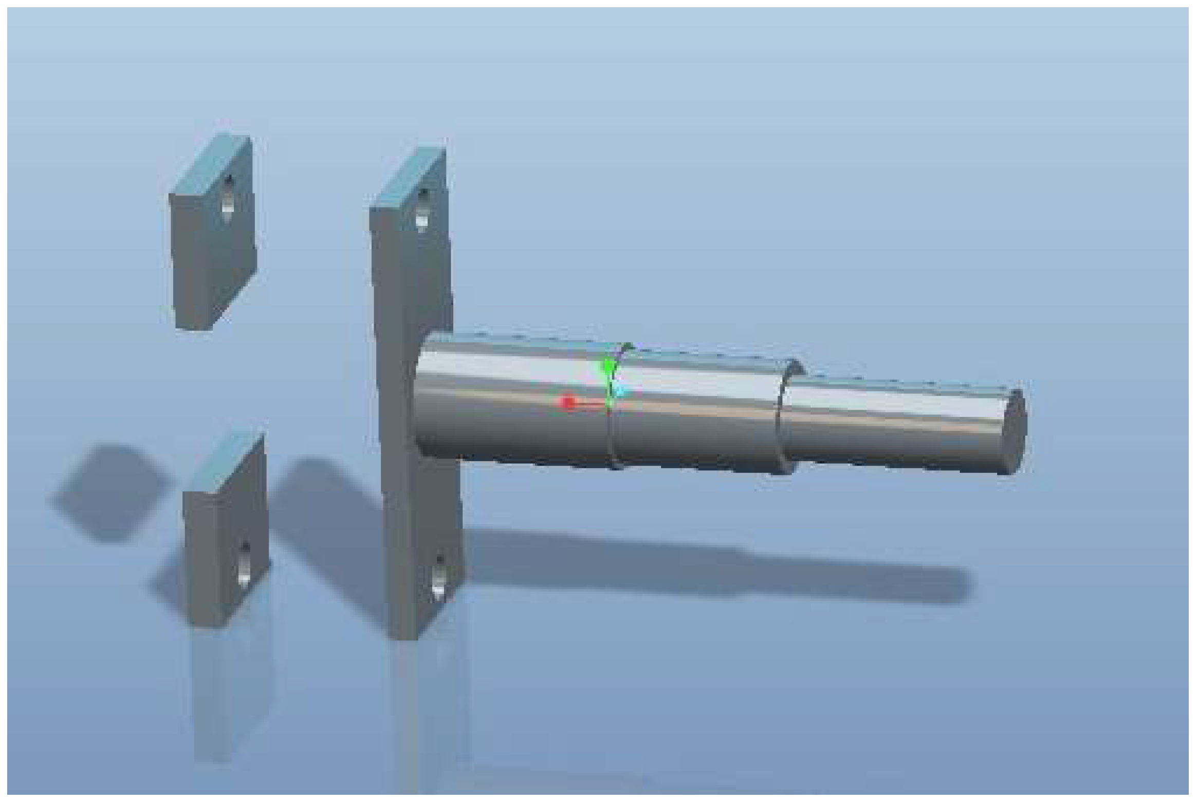
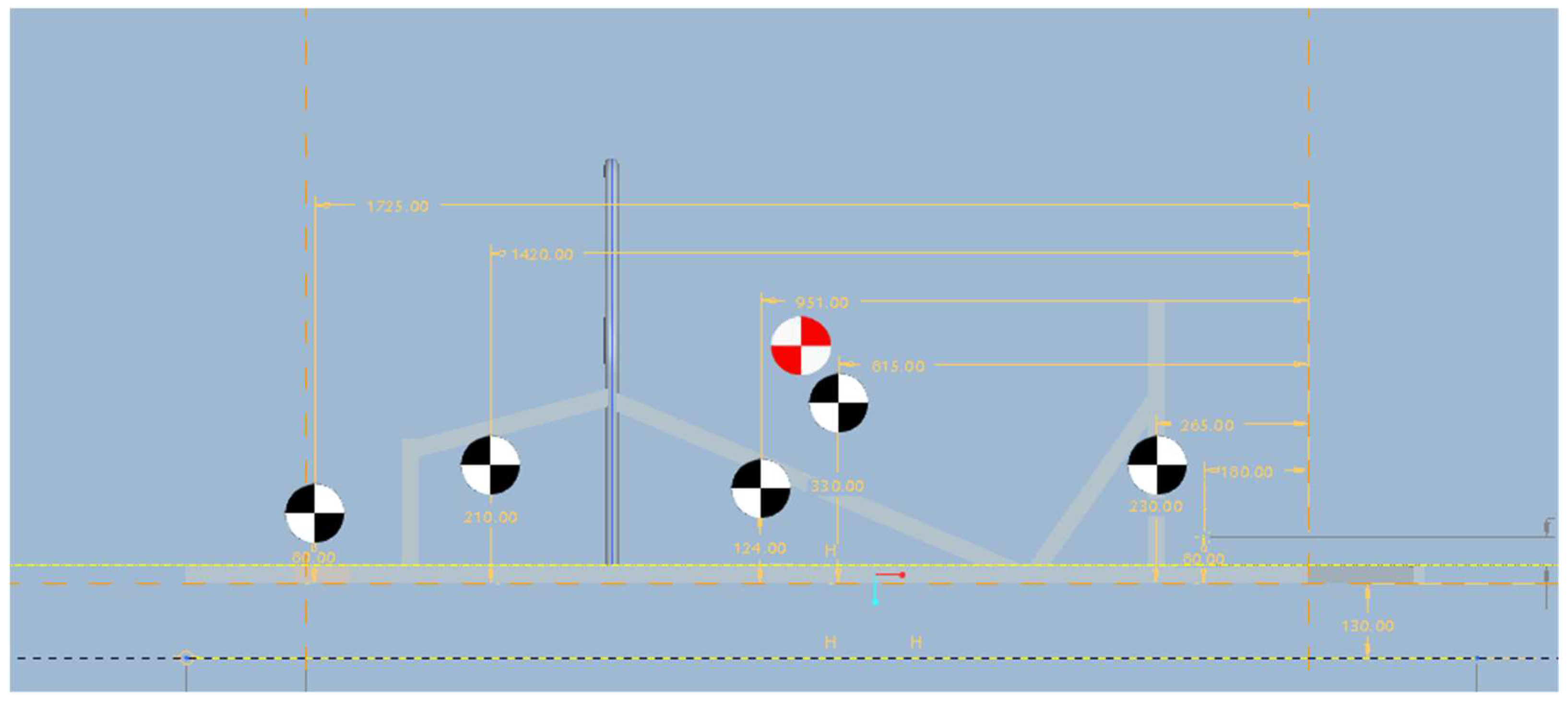
Figure 6.
Right view of the electric car’s centre of gravity.

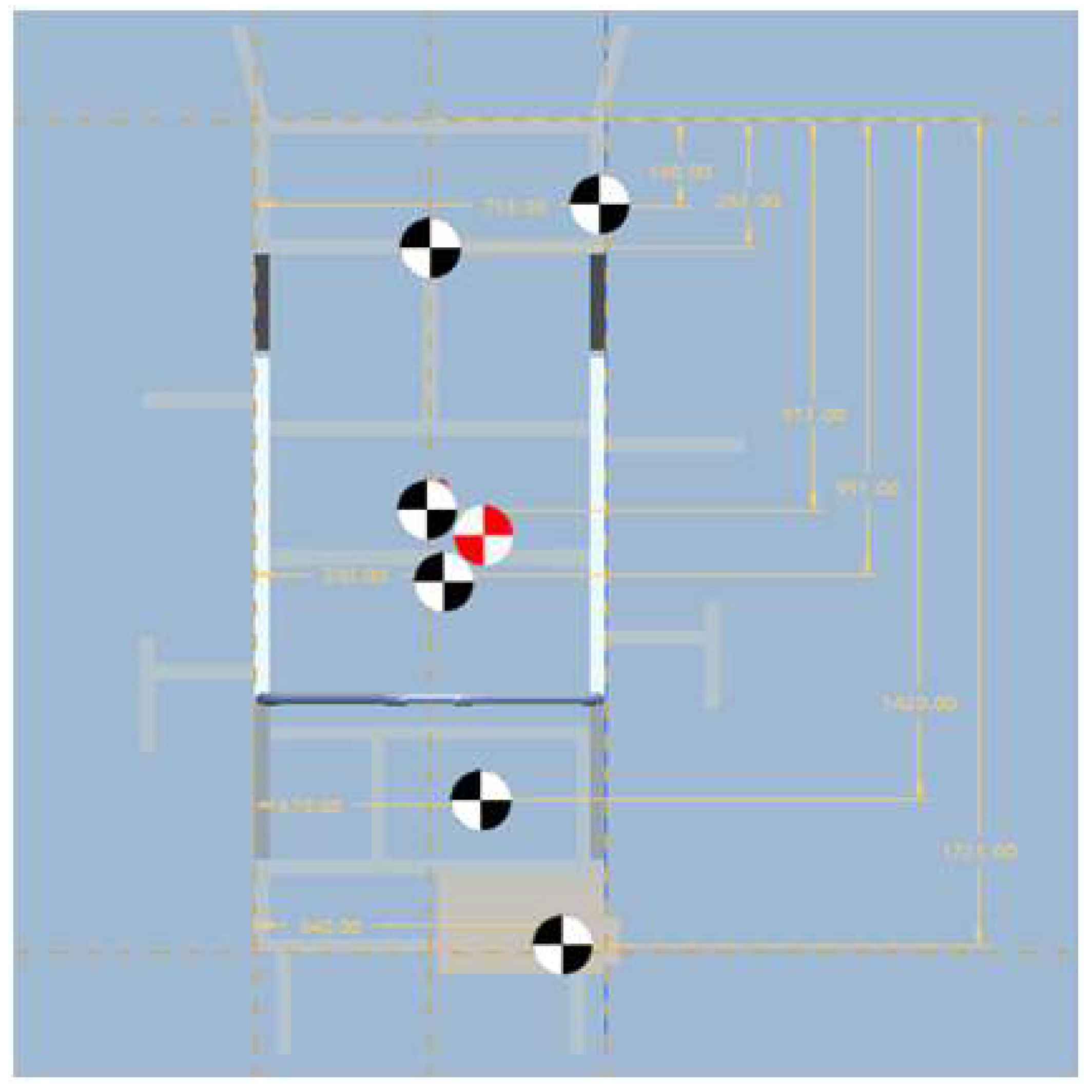
Figure 7.
Top view of the electric car’s centre of gravity.

Figure 8.
Manufacturing stages of the parts fitted on the chassis: (a,b) milling manufacturing; and, (c,d) turning manufacturing [7].
Figure 8.
Manufacturing stages of the parts fitted on the chassis: (a,b) milling manufacturing; and, (c,d) turning manufacturing [7].

Figure 9.
Electric car: (a) final product; (b,c) semi-finished product; and, (d) welding of the front and the rear semi-axle kits on the chassis; [3,7].
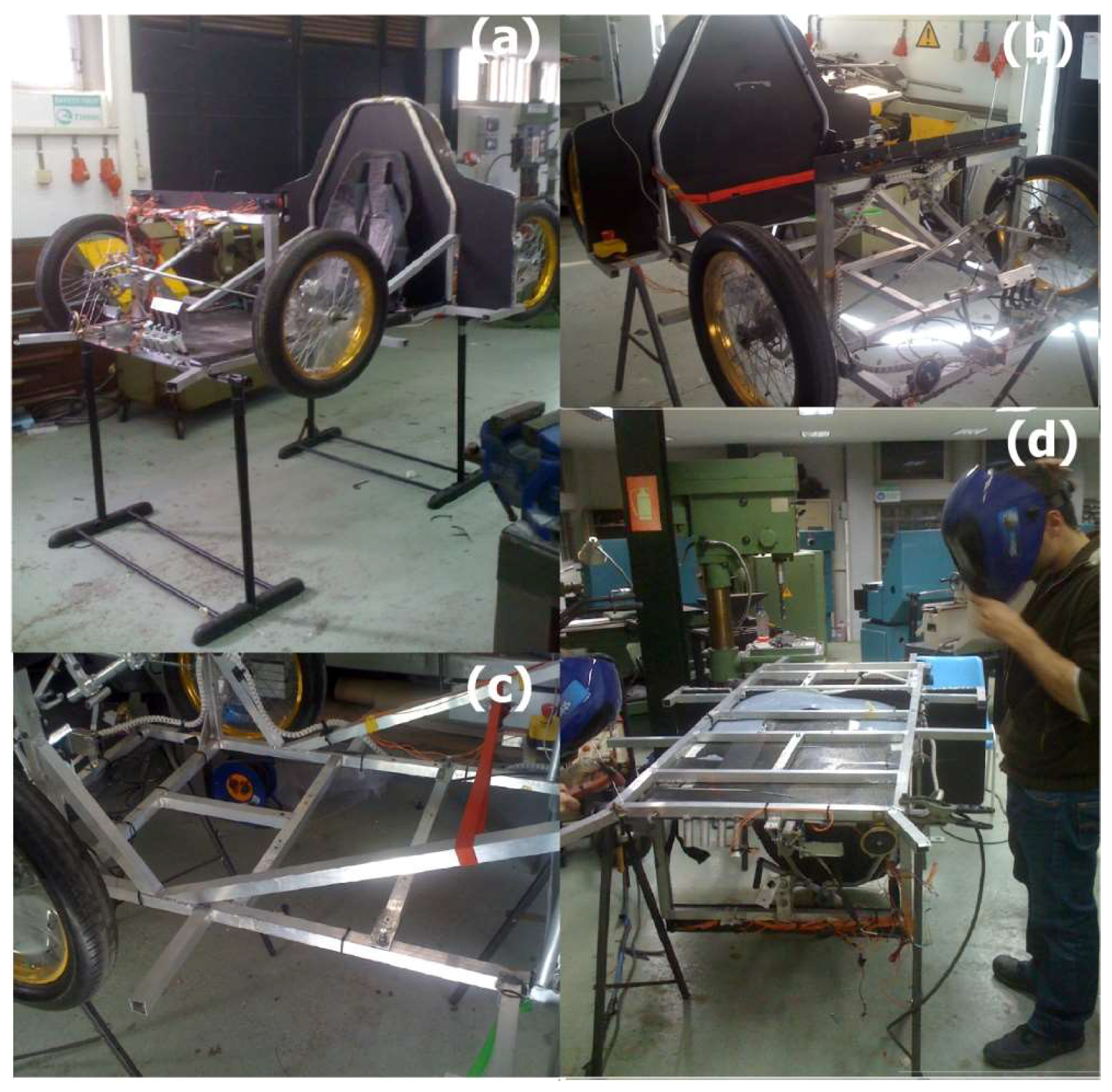
Figure 10.
The electric car of the Tuc Eco Racing team at the Shell Eco Marathon racing competition [3,7].

Table 1.
Component elements properties.
| Component Element Properties | % |
|---|---|
| Aluminium, Al | 95.2–98.3% |
| Chromium, Cr | ≤0.25% |
| Copper, Cu | ≤0.10% |
| Iron, Fe | ≤0.50% |
| Magnesium, Mg | 0.6–1.2% |
| Manganese, Mn | 0.40–1.0% |
| Other each | ≤0.05% |
| Other total | ≤0.15% |
| Silicon, Si | 0.70–1.3% |
| Titanium, Ti | ≤0.10% |
| Zinc, Zn | ≤0.20% |
Table 2.
Mechanical properties of the space frame chassis.
| Properties | Value | Unit |
|---|---|---|
| Elastic modulus, E | 70,000 | MPa |
| Shear modulus, G | 26,316 | MPa |
| Yield strength, σ | 255 | MPa |
| Poisson ration, v | 0.33 |
Table 3.
Mechanical properties of the parts fitted on the space frame chassis.
| Properties | Value | Unit |
|---|---|---|
| Elastic modulus, E | 207,000 | MPa |
| Shear modulus, G | 80,000 | MPa |
| Yield strength, σ | 850 | MPa |
| Poisson ration, v | 0.29 |
Table 4.
Chassis centre of gravity position.
| Lx (mm) | Ly (mm) | Lz (mm) |
|---|---|---|
| 951.025 | 385.413 | 254.894 |
Table 5.
Centre of gravity of the electric car.
| COGx (mm) | COGy (mm) | COGz (mm) |
|---|---|---|
| 872.766 | 392.328 | 408.793 |
© 2018 by the authors. Licensee MDPI, Basel, Switzerland. This article is an open access article distributed under the terms and conditions of the Creative Commons Attribution (CC BY) license (http://creativecommons.org/licenses/by/4.0/).
Share and Cite
MDPI and ACS Style
Tsirogiannis, E.C.; Siasos, G.I.; Stavroulakis, G.E.; Makridis, S.S. Lightweight Design and Welding Manufacturing of a Hydrogen Fuel Cell Powered Car’s Chassis. Challenges 2018, 9, 25. https://doi.org/10.3390/challe9010025
AMA Style
Tsirogiannis EC, Siasos GI, Stavroulakis GE, Makridis SS. Lightweight Design and Welding Manufacturing of a Hydrogen Fuel Cell Powered Car’s Chassis. Challenges. 2018; 9(1):25. https://doi.org/10.3390/challe9010025
Chicago/Turabian StyleTsirogiannis, Evangelos Ch., Gerasimos I. Siasos, Georgios E. Stavroulakis, and Sofoklis S. Makridis. 2018. "Lightweight Design and Welding Manufacturing of a Hydrogen Fuel Cell Powered Car’s Chassis" Challenges 9, no. 1: 25. https://doi.org/10.3390/challe9010025
Note that from the first issue of 2016, this journal uses article numbers instead of page numbers. See further details here.