Article

Cutting the Umbilical: New Technological Perspectives in Benthic Deep-Sea Research

1
Centre of Natural History—CeNak, Zoological Museum, University of Hamburg, Martin-Luther-King-Platz 3, 20146 Hamburg, Germany
2
Alfred Wegener Institute, Helmholtz Centre for Polar and Marine Research, PO Box 120161, 27515 Bremerhaven, Germany
3
DFKI-RIC Bremen, Department of Underwater Robotics, Robert-Hooke-Straße 1, 28359 Bremen, Germany
4
Department of Genetics and Evolution, University of Geneva, Sciences 3, Quai Ernest Ansermet 30, CH-1211 Geneva 4, Switzerland
5
Department of Physics and Earth Sciences, Jacobs University, 28759 Bremen, Germany
*
Author to whom correspondence should be addressed.
J. Mar. Sci. Eng. 2016, 4(2), 36; https://doi.org/10.3390/jmse4020036
Submission received: 5 March 2016 / Revised: 1 May 2016 / Accepted: 9 May 2016 / Published: 20 May 2016

Abstract

:
Many countries are very active in marine research and operate their own research fleets. In this decade, a number of research vessels have been renewed and equipped with the most modern navigation systems and tools. However, much of the research gear used for biological sampling, especially in the deep-sea, is outdated and dependent on wired operations. The deployment of gear can be very time consuming and, thus, expensive. The present paper reviews wire-dependent, as well as autonomous research gear for biological sampling at the deep seafloor. We describe the requirements that new gear could fulfil, including the improvement of spatial and temporal sampling resolution, increased autonomy, more efficient sample conservation methodologies for morphological and molecular studies and the potential for extensive in situ real-time studies. We present applicable technologies from robotics research, which could be used to develop novel autonomous marine research gear, which may be deployed independently and/or simultaneously with traditional wired equipment. A variety of technological advancements make such ventures feasible and timely. In proportion to the running costs of modern research vessels, the development of such autonomous devices might be already paid off after a discrete number of pioneer expeditions.

1. Introduction to Challenges

The deep-sea is the largest marine habitat on Earth in terms of geographic coverage [1,2], and we know only very little about its biodiversity [3,4,5,6,7]. It comprises continental slope areas down to abyssal plains and hadal troughs. Its sediment, organic carbon availability and faunistic composition differ tremendously with geographic area, geography and tectonics, latitude and productivity regime, currents, depth and age of the environment. Compared to ecosystems with a similarly high biodiversity, such as rain forests and coral reefs, life in the deep-sea is less well known. This is a direct result of the difficulties in accessibility and the often low densities of organisms across all size classes from viruses and microbes via protists to megafauna. These characteristics have led to a fundamental lack of understanding of the community structure of animals living at the deep seafloor. Questions, such as ”How many species are there in the oceans?”, “What are the geographic ranges of the species?”, “Are different ‘regions’ biogeographically distinct”, “What are the ecological and evolutionary drivers that shape biodiversity over days (rapid genomic changes) to millions of years (macro-evolutionary processes), respectively?” and ”How is biodiversity linked to deep-sea microbial ecology?” [8], remain unanswered. It is not well known whether dissimilarities in species composition between samples from adjacent localities represent a true spatial patchiness or whether this heterogeneous faunal composition is simply due to the low abundances of globally-distributed species. The limited number of standardized samples collected within surveys, which are comparable across campaigns and geographical regions, makes it very difficult to extrapolate species richness across large areas or even the entire deep-sea, independently of whether species accumulation or incidence-based statistical estimations are applied. In addition to the largely non-deciphered spatial patterns, not much is known about the deep-sea’s temporal faunistic succession, with responses to short-term extreme physicochemical events and long-term climate variation. Such information, however, is needed for a better understanding of evolutionary processes and ecosystem functioning, with these requirements forming the basis for applied research aspects, as well as developing deep-sea conservation and restoration methodologies [9]. The assessment of marine ecosystem goods and services, e.g., their biodiversity, the production of natural resources and oxygen, the sequestration of anthropogenic carbon dioxide and the recycling of nutrients, is increasingly attracting the attention of scientists and stakeholders To better assess these, there is a requirement for a substantial increase of the numbers of replicates and the area sampled from the deep-sea, a requirement that cannot be readily provided with current research gear and infrastructures.
This paper deals with technological aspect of biological sampling in deep-sea research. We describe technological problems, the lack of efficiency and limitations hindering these investigations and outline key concepts that could be developed to overcome these shortcomings.

1.1. Modern Research Fleets, but Old Equipment and Gear

Marine research on the high seas and within the deep-sea is performed from various modern research vessels. Many countries worldwide, via their marine research institutions, run extensive research fleets with several vessels providing international and multidisciplinary research. There are many countries that run modern research vessels; we here just mention a few, for example Japan (Jamstec, e.g., Karei, Kaiko, Hakuho Maru), France (Ifremer, e.g., Marion Dufresne, Pourquoi pas? L’Atalante, Thalassa), USA (Scripps, WHOI, e.g., Atlantis, Neil Armstrong), U.K. (NOC, e.g., Discovery, James Cook; BAS, e.g., James Clarke Ross) and Germany (AWI, GEOMAR, IOW, ICBM, e.g., Polarstern, Sonne, Maria S. Merian, Meteor, and others). Of these, the new RV Sonne is currently one of the most modern research vessels. Planning for the renewal of some of these research vessels is ongoing in several countries. The latest research ships are large, efficient and equipped with the most advanced navigation systems and onboard research facilities. However, for deep-sea research, we still depend on gear, such as corers or trawls very similar in design to equipment used during the infancy of deep-sea exploration more than a century ago.
Ocean technology employed in future biological surveys cannot be only autonomous gear, such as Autonomous Underwater Vehicles (AUVs), free-falling self-operating systems (bottom landers) with mounted cameras or sensors, or automated trap systems. Expensive manned submersibles are also not capable of addressing the full gamut of biological survey sampling. Remotely-Operated Vehicles (ROVs) are regularly used in marine research and are useful for sampling some areas of the seafloor selectively. However, these devices cannot sample efficiently the large numbers of animals necessary for any comparative biodiversity research of meio-, macro- or megabenthos for systematic, ecologic or evolutionary research. ROVs do not allow true sampling for high spatial resolution analyses of infauna or meio- and macro-epifauna, despite providing visual information on the density and coarse taxonomic composition (especially of mega-epibenthic assemblages), e.g., taking samples each 10 m along a 1000-m transect. Since the early exploration of the deep-sea from research vessels, such as Challenger, Galathea, Vityaz and others, bathyal, abyssal and hadal samples have been taken by varying corer systems, such as Van Veen, Petersen bottom grab [10,11], Okean-50 [12], video guided grabs (TV), box corers and multiple corers. Most of these provide only small samples of seafloor sediment (with captured inhabitants), and these small volumes (see Section 2) already limit many forms of analyses. The catchability of trawls varies very much on their design and catch focus; thus, different nets are used for different scientific investigations. Agassiz trawls or otter trawls are characterized by large mesh sizes, typically of 20 mm with cod ends of 10 mm nets, capable of collecting only a small number of macro-invertebrates in the samples [13]. Epibenthic sledges originally deployed by Sanders et al. [14] and Hessler and Sanders [15] also were equipped with larger mesh sizes, until fine meshed-sized epibenthic sledges were constructed [15,16] and used during later deep-sea expeditions. This type of epibenthic sledge has later been equipped with camera and sensor systems and yielded high numbers of specimens for deep-sea research [17,18].
During the Vema-TRANSIT expedition (December 2014 to January 2015) with the new German research vessel Sonne, the hadal depths of the Puerto Rico Trench were sampled for the first time with fine-meshed gear using an epibenthic sledge with a cod end of 300 µm, yielding a much higher number of macrofauna than previously reported from hadal depths. For example, 151 specimens of isopods were sampled at a single station (>8300 m) in the Puerto Rico Trench by the RV Sonne [19]. On the contrary, from the Galathea expedition, 83 specimens of bathyal and abyssal isopods were sampled from across 22 stations [20]; at hadal stations a total of 53 specimens were sampled at 11 stations [21]; thus, the Galathea expedition yielded a total of 136 isopod specimens from all deep-sea stations investigated. Deep-sea research at hadal depths, including the description of available deep-sea gear from corers and trawls to lander systems, baited trap ROVs, AUVs and manned submersibles, has been comprehensively reviewed by Jamieson [21].

1.2. Challenges of Future Biodiversity Research: Modern Effective and Efficient Time-Saving Gear

For more than a century, marine biologists have sampled the deep-sea bottom fauna with various kinds of towed nets providing semi-quantitative to non-representative samples. Alternatively, grabs provide quantitative samples; however, both kinds of gear (towed nets and grabs) are rather time consuming to deploy and become even more so with increasing ocean depth. Imaging methods applied for more than half a century usually cover larger areas of seafloor, areas which may be of sufficient size, to allow general conclusions on epi-/mega-faunal densities to be drawn, but they do not yield physical samples for precise species identification or for advanced studies on life history traits.
The modern gear that is trawled behind research vessels, such as fine-meshed epibenthic sledges, collects a high number of macro- or megafaunal animals, commonly yielding far in excess of 10,000 invertebrates per expedition [17,18]. Nevertheless, one deployment of trawled gear, such as an epibenthic sledge, needs long wire times and is therefore very expensive if we consider the ship time and the daily cost of modern research vessels. For example, one deployment of an epibenthic sledge takes about 6 h at 5000 m, 7.5 h at 6000 m, 9 h at 7000 m or 11 h at 8000 m. Often, two deployments are performed per station in order to allow for the collection of replicate material and also for different fixation techniques (e.g., ethanol if samples are to be purposed for later genetic study or formalin for histology). On this basis, we have to calculate an average of 15 h per abyssal deployment, which means 30 h for two epibenthic sledge deployments per station and a minimum 300 h (12.5 days) of ship time at abyssal depths for 10 stations. This equals 625,000 Euros in expenses for ship time (if we roughly consider 50,000 Euros as the daily cost for a modern research vessel) per expedition if only 10 stations are sampled. It must also be taken into account that the expenses rise with increasing depth of deployment (e.g., hadal trenches). For further studies, including DNA sequencing, the material has to be sorted, selected and deep frozen or fixed in ethanol or RNAlater® solution, which additionally increases the time and costs of sample processing. As a consequence, modern deep-sea biodiversity research urgently requires the development of time-saving gear, which combines the possibilities and capabilities of contemporary gear in use. This new equipment should then be applied in accordance with an advanced sampling design [22,23]. A higher efficiency of sampling operations ideally includes the potential to increase the number of independent samples taken autonomously during one sampling operation relatively independently from deep-sea wires and thus of the research vessel’s time. It also has to selectively or unselectively take samples for in situ real-time studies, including modern genomic and metagenomic approaches. Thus, the only possibility for saving ship time and expenses is to deploy an efficient gear for sampling benthic animals independently from the deep-sea wire. Autonomous sampling at the seafloor can be performed, while other scientific surveys or sampling are continued from the vessel at the same time. In our opinion, the development of novel deep-sea sampling gear is as important as the development of new research vessels and, therefore, has high priority.

2. State of the Art of Deep-Sea Benthic Research Gear

Traditional sampling of larger quantities of bottom fauna for the study of deep-sea benthic communities is generally rather time consuming. However, sampling methods and sample processing vary in complexity and approach according to the size class of the benthos that is targeted. Of the three size classes that are commonly studied, the mega-, macro- and meiofauna, the megafauna include all epibenthic vertebrates and invertebrates visible to the naked eye or a camera system (>1.5 cm) [24,25]. The macrofauna is defined as organisms retained on a sieve of usually a 0.25- or 0.3-mm mesh size, while the meiofauna as those organisms retained on 63-, 42- or 32-µm meshes. For molecular work, it is critical to process material quickly before DNA degradation takes place, e.g., in cold 96% precooled ethanol or acetone. However, in some cases, ethanol-fixed samples are rendered useless for morphological analyzes, and formalin-fixed material is needed for morphological studies. Photographs of fresh material comprising entire organisms can be important for identification purposes and must be taken prior to preservation, after which specimens tend to lose their color.

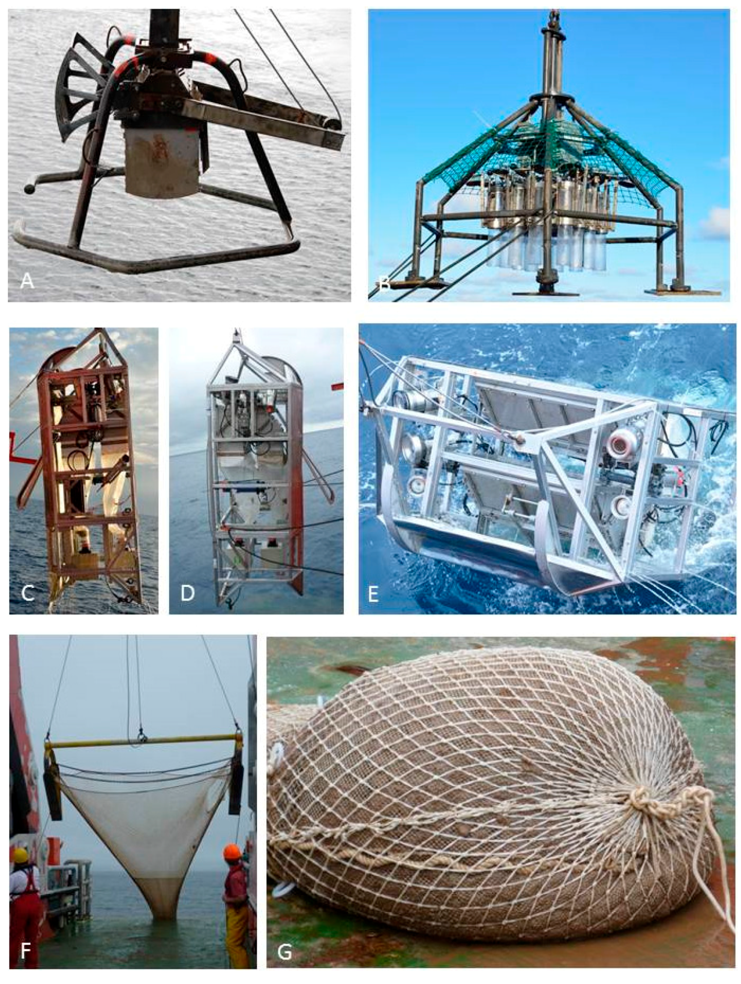
2.1. Wire-Dependent Systems (Corers, Dredges, Epibenthic Sledges, Trawls, ROVs)

Gear typically used for the sampling of larger quantities of benthic deep-sea organisms for systematic, evolutionary or ecological studies is described and partly illustrated by Eleftheriou and McIntyre [12] and Jamieson [22]. Corers are used to sample animals in or on soft sediments. They are mostly regarded as quantitative gear despite the potential loss of material due to the bow-wave effect during deployment [12]. Selected gear being deployed using deep-sea wire is illustrated in Figure 1.

2.1.1. Quantitative Sampling: Samples of a Defined Surface Area

Standard gears for the collection of meiofauna in unbiased abundance and with intact morphology are the Multicorer (MUC) with 6.2-cm diameter corers or the Megacorer (MC) with a 10-cm diameter, with both MUCs and MCs using a rosette of tubes to collect undisturbed samples of sediment and overlying water. Of the two, the MUC corer is most suitable for meiofauna because of the small surface area sampled. The megacorer is recommended for the collection of sufficient specimens for taxa with lower densities to be identified. Replicates are retrieved from repeated, close proximity deployments. Cores from the same deployment are considered as pseudoreplicates. After measurements of the core lengths, the water is collected over a 32-µm sieve. The cores are processed immediately after retrieval on board, kept cool and, if possible, processed in a cold room at in situ temperature. Virtually undisturbed cores are sliced in vertical layers of 0.5 cm for the upper cm, followed by layers of 1 cm up to 5 cm for biodiversity studies. For ecosystem functioning studies, it is often relevant to analyze the sliced cores from up to a 10-cm depth. The sediment is frozen, fixed in 96% ethanol or borax-buffered formaldehyde to an end concentration of 4%. Filtered seawater is used for the dilution of the formaldehyde.
If the sediment permits the employment of a Box Corer (BC), which samples 0.25 m2 of the seafloor (the Sandia box corer is additionally divided into 10 × 10-cm sub-cores), it should be used for macrofauna collection, as it allows for subsampling with a defined area and gentle handling of the sample when extracting the top sediment layer. An undivided box corer is preferable in sediments with stones (e.g., dropstones from icebergs in polar waters or manganese nodule provinces), sand or over-consolidated clay, the recommended sieve size is 300 µm (250 µm may be used, but coarser is not recommended). For both sampling devices, a pinger or a video camera can be attached to the wire just above the shackle to determine accurately the distance of the gear to the bottom and to verify bottom contact. The latter is difficult to deduce from the wire tension alone, as at great depths, the weight of the wire is considerably higher than that of the gear itself, and large open ocean waves obscure the vibration signal further.

2.1.2. Qualitative Sampling: Samples of Greater Size, but with Undefined Area Coverage

At great depths, trawled gear provides extremely useful information on larger species because densities of individual species tend to be very low, but species richness is nonetheless high [26]. As trawled nets of any kind cover a much larger area than a coring device, it is most advisable to use both nets and corers.
Epibenthic sledges collect macrofauna from the upper layer of sediment, the sediment water interface and the overlying water column to 1 m above the bottom. The sledge is towed over a distance defined by standardized time limits. Samples are collected in the cod end of the trawl net, by a sampler that consists of a plastic cup with a 300-µm mesh screen at the sides. If a large amount of sediment is collected, the sample is sieved in a similar fashion to those collected with coring devices. Recently, a Camera-Epibenthic Sledge (C-EBS) especially designed for sampling small epibenthic and supra-benthic fauna of roughly a few millimeters to one centimeter size at any depth and from any substrate was used successfully [17,18]. The C-EBS is equipped with supra- and epi-benthic samplers possessing plankton nets of 500 µm and a cod end of 300 µm as described by Brandt and Barthel [15] and Brenke [16]. An opening-closing device prevents pelagic fauna from being caught during heaving. The haul distances are calculated using the time and the speed (ship speed with 1 knot and then winch speed with −0.5 m/s), until the C-EBS has left the ground, which is indicated by the tension meter. As the haul length varies, the data are standardized to 1000-m2 hauls for comparative analysis. The C-EBS is also a carrier for an autonomous digital underwater video and a still camera, with the required energy and control units deployed in situ, as well as the system being equipped with sensors (Seaguard RCM DW) for measuring data on temperature, pressure, conductivity and oxygen concentration [17]. Brattegard and Fosså [27] showed that different hauls of epibenthic sledges repeatedly used to sample a particular station in most cases collect a different selection of fauna because of the patchiness of many species’ distributions in the deep-sea and because trawled gear seldom hits the same spot twice when repeating a station. However, this is an important aim of some scientific approaches, especially when biodiversity dynamics is studied over time in monitoring programs. On deck, the complete samples (except freshly-picked material for biochemical analyses) is immediately transferred into chilled (−20 °C) 96% ethanol and kept in a −20 °C freezer for at least 48 h for subsequent DNA studies in order to avoid DNA degradation [28].
Large and highly motile megafauna are often caught with various trawls (otter trawl, beam trawl or Agassiz trawl), occasionally also with large amounts of sediment, which then has to be sieved either entirely or as a subsample of a standardized size (e.g., 5 L). After photographic documentation of the material and selected specimens or species, morphological and molecular preservation is carried out. In the case of large animals, small pieces of tissue are sufficient for DNA studies (precooled 96% ethanol, −80° freezing or freeze of tissues using liquid nitrogen) so that the specimen can be used for museum collections. Fixation of large megabenthos is done in a minimum of 4% formaldehyde in seawater (= 10% formalin), buffered in borax. After approximately six months, a transfer of specimens to 70% ethanol, following several washes in freshwater, is recommended.

2.1.3. Optical (Camera-Based) Methods

Most important and essential for statistical analyses of much biodiversity research is data on the absolute abundance of the epifauna. Direct observations of epi-/mega-fauna have been successfully made of deep-sea surveys for more than six decades [29] with these surveys also providing a number of important biological and environmental information. In addition to the density and possibly the biomass (if additionally animals are sampled and weighed), imaging methods provide spatial information on how animals are associated with each other, on selected characteristics of behavior, and they also provide general impressions of the seafloor and of environmental conditions (e.g., grain size, soft, gravel, bedrock). However, imaging methods do not allow a final identification of all observed species and do not provide material for further morphological or genetic identification or analyses of ecological, as well as the physiological status and performance of species or individuals. For the most essential biological information of the occurrence and abundance of target taxa, as well as associated parameters, imaging methods provide results with a high spatial resolution, e.g., for each centimeter of a still photograph or for each meter of a kilometer-long video transect. Cameras have been mounted on trawls and dredges, as well as long-lines and grabs to observe simultaneously the sampling procedure, including the undisturbed areas ahead of the sampling equipment, to assess in situ abundances of epibenthic organisms, as well as the catch efficiency of trawls (for a recent exemplary application, see [30]). Moreover, stationary observations have been carried out using time lapse cameras combined with baits or traps, which show small-scale processes, e.g., biodiversity succession due to enhanced food availability at different trophic levels, grazers or scavengers [31]. Such videos or composed stills have a pre-defined temporal resolution, e.g., a picture taken each minute by a timer system throughout a long deployment or full video footage over shorter periods. The most important improvements in the past decades have been the increase in the optical resolution of the camera and the underwater spatial positioning of the platforms on which the cameras were mounted, such as the simple towed systems without bottom contact, yo-yo operated devices, submersibles, ROVs, AUVs, glider and crawler and landers (e.g., [32]). Recently, the new C-EBS [17] was used in order to collect fauna, environmental parameters and video, as well as still photography simultaneously during the complete sampling period at the seabed.
A Sediment Profiling Imagery (SPI) system has proven to be a helpful method in acquiring an impression of the sediment type, the infauna and the sediment-water interface. Several images can be taken during one cast from different locations in a defined area by repeatedly lowering and heaving the device. Thus, information with a relatively high spatial resolution can be provided (e.g., [33]). The camera system works like an inverted periscope. A prism filled with distilled water is placed in front of the camera lens. This prism is then pushed into soft sediment for 15 to 20 cm. The prism reflects the light from the vertical sediment profile into the lens of a camera. The frame of this system can be outfitted with a surface still photo camera. The system is battery powered in its current state, but real-time observation via a cable is in principle possible. Several sedimentary parameters, such as grain size, degree of oxygenation, layering and biogenic structures (burrows, etc.), presence and thickness of an organic fluff layer on the surface and general flow regime (depositional versus erosional) can be determined from profile images with a specific image analyzer software.

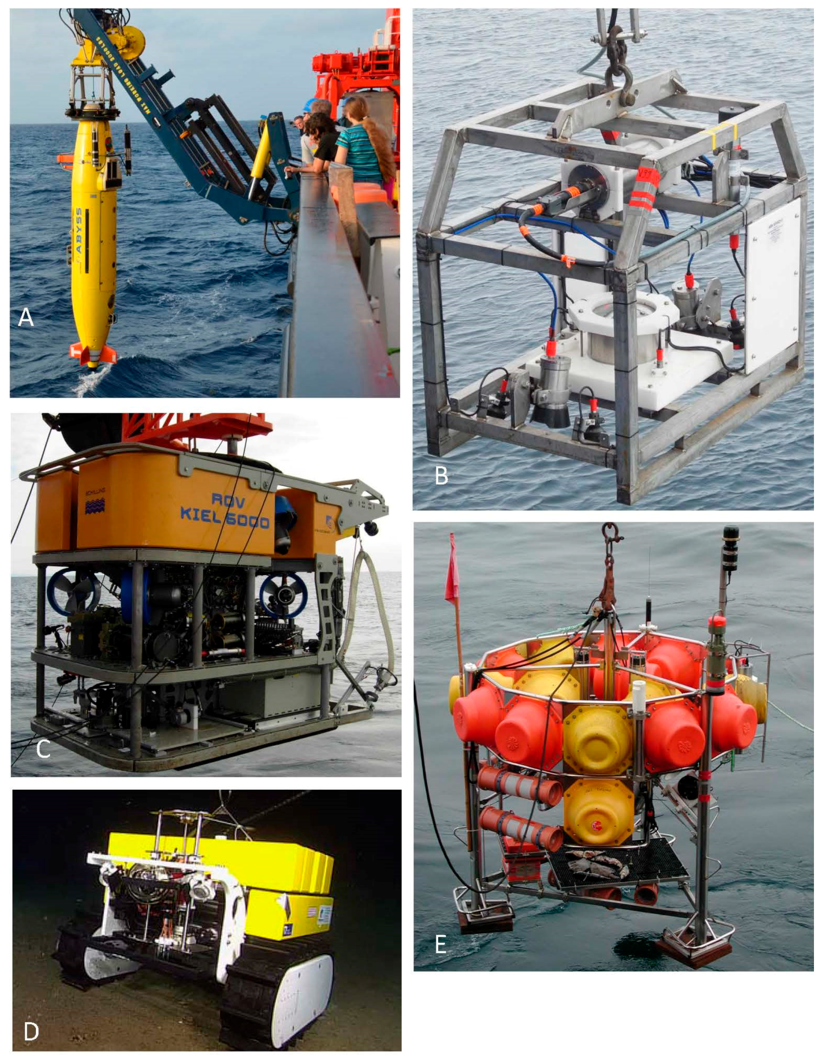
2.1.4. Remotely-Operated Vehicles

Remotely-Operated Vehicles (ROVs) are unmanned, highly maneuverable (if compared to corers or landers) and controlled underwater robots operated from aboard a vessel [34,35]. They allow surveys to take precise samples and to conduct experiments at the deep seafloor. Although manned submersibles exist that can transport humans to these depths, ROVs are a more compact, portable and practical alternative without any human risk.
ROVs are linked to the ship by a so-called umbilical, i.e., a group of electrical and fiber-optical cables that carry power, high-definition video and data signals back and forth between the vehicle and the control station. ROVs are equipped with a video camera and lights as a minimum payload. Additional equipment is commonly added to expand the vehicle’s capabilities. A science ROVs’ instrumentation suite may include still and video cameras, manipulators, sonars, magnetometers, water samplers and instruments that measure temperature and other water properties.
Remotely-operated vehicles vary in shape, size and capability depending on their work class. Micro- or mini-class ROVs are small systems able to be transported and deployed by one person without outside help [36]. Micro- and mini-classes are referred to as the “eyeball" class to differentiate them from ROVs that may be able to perform intervention tasks. Intermediate size systems, so-called light work class ROVs, may be able to carry some manipulators. They typically have a maximum working depth of less than 2000 m. Heavy work class ROVs often carry at least two manipulators. Many of these have a working depth up to 6000 m. Together with their monitoring and control equipment, launch and recovery systems, umbilical controls and winches, heavy work class ROVs are a complex array of electrical, electronic, hydraulic and mechanical systems.
ROVs can be maneuvered precisely with their thrusters (propellers). Through their eyes (cameras), the manipulators (hands) can be used to select and recover small, delicate objects more precisely than any other sampling system. Scientists can see the undisturbed area from where samples are selectively taken, providing them with a better understanding of habitats and structures. Complex in situ experiments can be achieved maintaining the environmental conditions and minimizing sample damage caused by their transfer to the surface [37].
Several scientific ROVs have tool-drawers, i.e., metal frames that are bolted underneath the main body of the ROV, outfitted for various missions. By putting most of the discipline-specific tools on the tool-sled, it is easy to switch the tools out, e.g., from a biology dive to a geology dive, which minimizes the turnaround time between dives. For instance, scientists studying the delicate animals in the water column may use a suction sampler (“slurp gun”) that transfers animals into a storage container, while scientists studying the ocean floor might use push cores, i.e., plastic tubes that are pushed into the seafloor to pull out samples of the sediment for further study.

2.2. Untethered Autonomous Systems (i.e., Bottom Lander, Crawler Systems, Autonomous Underwater Vehicles)

The conventional approach in deep-sea studies is to collect samples, to recover them and to make observations and analyses on board the research vessel or later at the home lab. However, because of artifacts induced when samples are subjected to changes in hydrostatic pressure and (often) temperature during transfer to the surface, accurate data from the deep-sea are difficult, if not impossible to obtain. For many research questions, it is therefore preferable to carry out observations, experiments and measurements in situ. Such studies can be conducted using stationary and mobile systems. “Bottom landers” provide the opportunity to conduct stationary work at the seafloor, while crawlers combine the capability of conducting measurements and experimental work at the bottom with the ability to (within limits) vary the area of investigations. Preprogrammed Autonomous Underwater Vehicles (AUV) are typically used to cover larger areas in upper water layers or above the seafloor with measuring and recording devices or camera systems (Figure 2).

2.2.1. Lander Systems

A bottom lander can be deployed from vessels of any size and is an unmanned vehicle that falls to the seafloor unattached to any cable, subsequently operating autonomously at the bottom. The type of lander system to be deployed depends on a number of factors, including the number of instruments to be carried, how deep in the ocean it needs to go and how long it needs to stay there [38]. A typical bottom lander consists of two sections: a buoyant upper section, which contains the instruments and sensors, and a heavy lower section, which keeps the lander on the seabed. At the end of the deployment, ballast weights are released pre-programmed or on acoustic command, and the lander ascends to the surface by its floatation.
Bottom landers are used as platforms for various in situ measurements at the seafloor; their specific payload or scientific module is determined by the scientific measurement or experiment. The platforms are typically deployed in the conventional free-fall mode, where the lander is released from the vessel at the sea surface [39]. However, many scientific objectives addressing specific morphological features, such as cold seeps, mud volcanoes or particular benthic communities, require a targeted and smooth lander deployment. For these requirements, launching devices connected to the ship’s coaxial or hybrid fiber optical cable are used to lower the bottom lander. The launcher carries the telemetry, cameras, lights and an electric release to separate the lander from the launcher on command [40].
Some bottom landers are designed to release data capsules at specific time intervals to send information back to the laboratory using a satellite telemetry system. The data capsules itself may be lost, but these systems eliminate the need to use a ship for data recovery, the cost of which may far outweigh the cost of replacing the lost equipment [41]. An example of an autonomous seafloor vehicle, a combination of a central lander and a mobile robot, is presented in Figure 3. This robot system is in a final stage of development and will start operations in the deep-sea in 2017 [42].

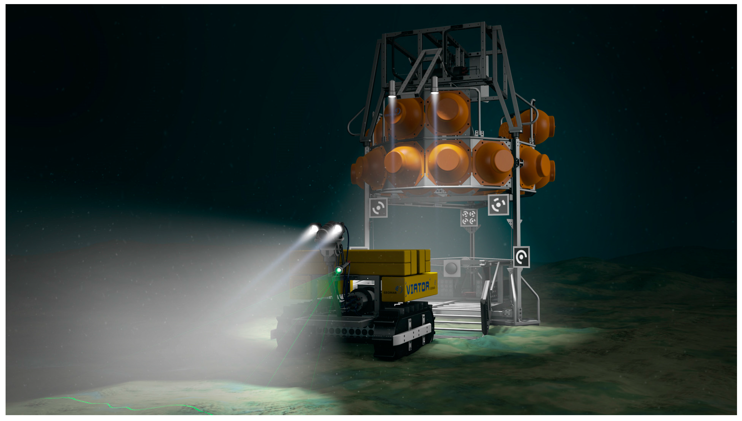
2.2.2. Crawler Systems

Environmental conditions within sensitive seafloor ecosystems, such as cold seep and hot vent provinces or cold-water coral reefs, vary temporally and spatially over a range of scales. They are regularly monitored via short periods of intense ship-borne activity or low resolution, fixed location studies by lander systems. In recent years, cabled research infrastructures have enabled sensor packages to receive power and transmit data from exploration sites in real time. By attaching mobile robots to these cabled networks, the investigation of spatial and temporal variability in environmental data is a possibility [43,44]. The mobility of robots is a vital element for research missions: they can explore a region, increasing the science return from the deployment and adding a spatial element to the collected data, in contrast to fixed location static landers. Two main mobile concepts have thus far been developed: a wheel-based system for extended deep-sea missions and a caterpillar system for high resolution small surface region exploration (up to 1 km2) in the deep-sea. In both cases, sufficient on-board intelligence for path planning and determining the best trajectory to follow is needed. Semi-autonomous or Internet-controlled crawler systems are the first step towards this new development. They are designed as a universal sensor transporting system for the temporal and spatial exploration of most regions of deep ocean floor. In addition to collecting a unique high resolution temporal dataset on environmental parameters, such as methane concentration, temperature, conductivity, turbidity, chlorophyll concentration and flow conditions, the vehicles have collected image data on faunal abundance, features and behavior [44]. The robot technology allows high mobility in terrain of medium roughness and may carry payloads of up to 120 kg without intense sediment penetration. A mobile system can also move to other areas of the seafloor. Such a teleoperated version of a mobile seafloor robot with a 70 m-long umbilical is connected to a junction box of the Ocean Networks Canada project (ONC) at a 870-m water depth in Barkley Canyon in the Northeast Pacific ([43]; Figure 2D). The crawler has been in operation since 2010 [44,45]. Maintenance work and exchange of the robot occurs once every 12 to 18 months. The autonomous versions of these mobile robots should be able to return to a central station, equipped with enough battery power to recharge the crawler to allow multiple missions (Figure 3). Two prototypes of these new intelligent “iCrawlers” are in the final stage of development within the Robotic Exploration of Extreme Environments (ROBEX) project [42] and will be deployed off Svalbard in 2016 and 2017.
A prerequisite of autonomous operations in a mobile system is the ability to perform navigation. This can be split into localization, mapping and control of the vehicle. Additional behaviors, such as exploration, coverage, obstacle avoidance and scientific sampling are built on top of this. These behaviors need to be managed to assure consistency with the state of the system and to sequence them according to the mission description. This ROBEX iCrawler can either work fully autonomously or in connection with any cabled observatory to carry out pre-determined autonomous operations with real-time data supply. Then, the crawler can monitor and study an area of sediment surface proportional to the length of its umbilical cable.
A fully autonomous iCrawler is equipped with lithium polymer accumulators (24 V/80 Ah) and follows pre-determined missions on the seafloor, creating baseline maps with video-mosaics from the environment and geo-referencing all incoming sensor data to create one GIS map. The crawler will automatically avoid obstacles on the seafloor. A typical monitoring mission will last 0.5 to one years. During these missions, which allow one to cover 0.2 to 1 km2 of seafloor, all data will be stored and retrieved after recovery of the instrument or during ROV maintenance. On demand, an emergency ascent through the water column with subsequent contact of the operational center allows the crawler to react on environmental incidents which demand a fast response. A final development stage is reached when an iCrawler can return to a central station/junction box for data transmission and energy supply (Figure 3).

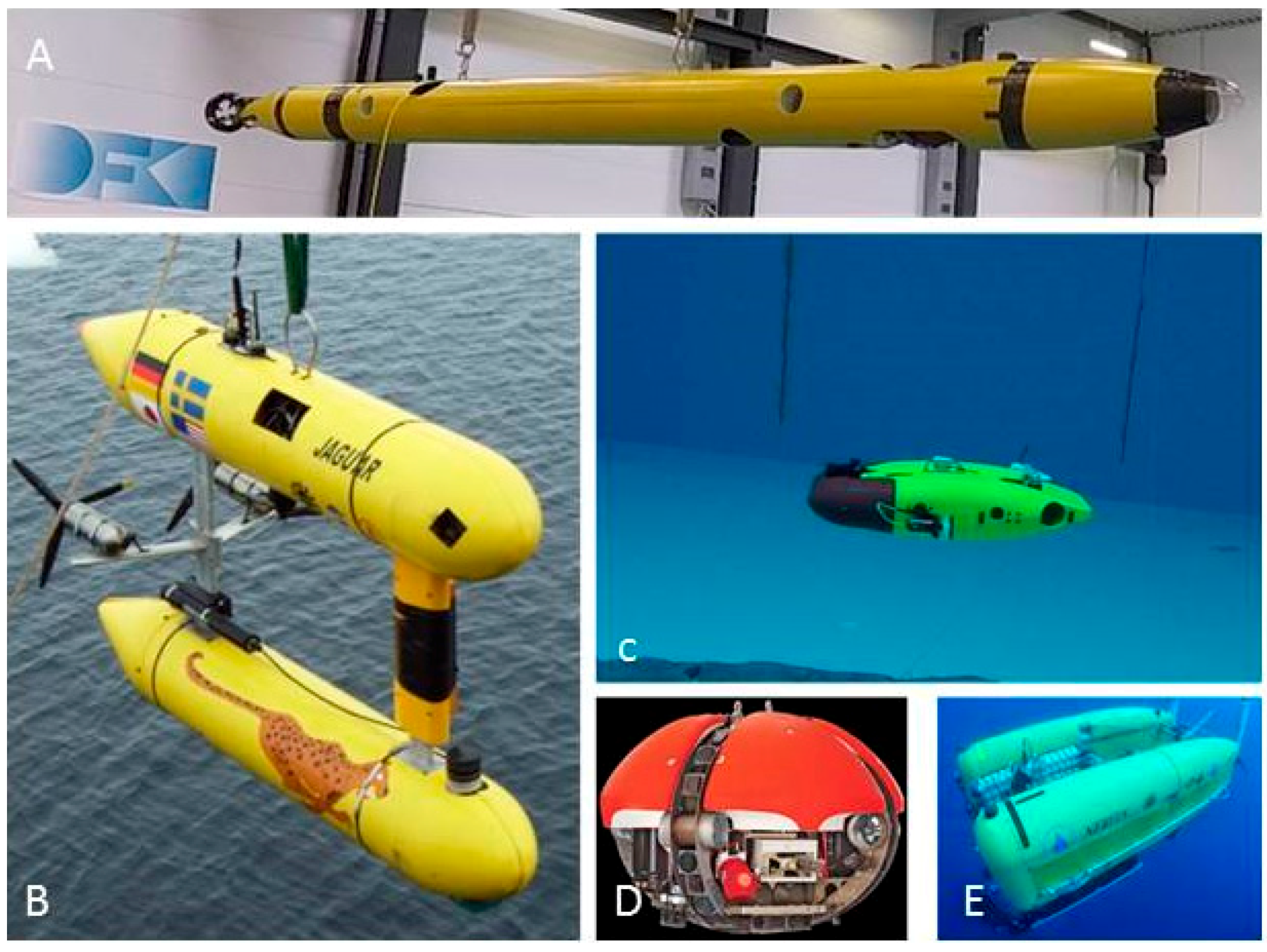
2.2.3. Autonomous Underwater Vehicles

Autonomous Underwater Vehicles (AUVs) are cable-less systems that can operate independently from the research vessel (though being deployed from it). These can be used for a wide range of different research questions. Since there are a large number of different AUVs and AUV concepts, only a few important systems are described in the following sections and illustrated in Figure 4. Figure 5 presents the spatial and temporal coverage of different sampling devices.
The differences in shape, weight, depth-rating, endurance and instrumentation directly reflect the different application scenarios for which AUV vehicles were designed. A common ground for all systems is their autonomy, meaning they have sensors, computation, energy and mobility on-board and can be used without external monitoring for some length of time.
For example, the SeaBED AUV class was developed by the Woods Hole Oceanographic Institution in the early years of the millennium and has since then been put to extended use. Specifically designed as a vehicle for close-range tasks, such as side-scan bathymetry and visual bathymetry [46], it was a new approach in the mid-size AUV class. Its extensive sensor suite, as well as excellent roll stability makes it the ideal vehicle for tasks that require detailed data of small underwater areas, such as underwater archeology [47]. This AUV class is used extensively by a number of laboratories world-wide, including the National Sun Yat-Sen University in Taiwan and the Australian Center for Field Robotics at the University of Sydney.
The “Dagon” AUV was designed and built as a scientific AUV for visual mapping and localization by DFKI-RIC in 2009 [48] as part of the CUSLAM-project, funded by the German Federal Ministry of Economics and Technology according to a resolution of the German Bundestag. The main goals in the design were to provide a platform for conducting experiments in the area of visual mapping and localization. Its high quality stereo camera system acts as the main sensor system for this application and is supplemented by the internal Inertial Measurement Unit (IMU) and pressure sensors. Using visual odometry and SLAM approaches, a map of the seafloor and the vehicles trajectory over the seafloor is generated. In order to validate the measurements made by this visual approach to mapping and localization, the complete additional navigation instrumentation available (Long-Baseline-Localization (LBL), Doppler Velocity Log (DVL), Fiber-Optic Gyroscope (FOG)) allows a second independent measurement to be recorded. This second measurement can then be used as a ground-truth for judging the quality of the visually generated data [49]. Dagon is a hovering AUV; it does not rely on forward movement to keep its current depth. This makes actuation more complex, but enables unique maneuverability in a wide range of environments. Dagon’s six thrusters give it five degrees of freedom; only the roll axis cannot be actively controlled. This last axis is kept passively stable by the catamaran shape of the vehicle. The stereo camera system is mounted in the two heads of the AUV, which offer a 180° range of tilt. Together with the hovering capability, this enables not only seafloor mapping, but ship-hull inspection or even under-ice mapping/localization. The camera system is capable of recording four hours of uncompressed HD (1920 × 1080) video at 30 FPS; from both cameras simultaneously. Combining extremely sensitive CCDs in the cameras with large-aperture (F = 1.4) wide-angle (64° in water) lenses creates precise and feature-rich underwater imagery.
The AUV has a nominal operating time of six to ten hours, which may vary with the type of mission. It can either be used as a completely autonomous vehicle, with the only communication available being the low-bandwidth acoustic modem, or together with a fiber-optic cable for telemetry. Using this cable, a hybrid ROV-mode is also possible, where control is done by a human operator or a control station on shore. An overview of the instrumentation of the vehicle is given in Table 1.
The AUV “Leng” has been developed for a very special requirement: fit through a hole as small as possible while maintaining a very high standard of instrumentation, endurance, mobility and reliability. This requirement stems from the mission profile, where the AUV is to be transported to its destination below a closed surface of ice by an ice-shuttle system (Figure 6). This should enable exploration of the Antarctic ice-shelf, but also a mission to Jupiter’s moon Europa and its ocean enveloped by a thick layer of ice could be imagined. The work on the AUV Leng and the ice-shuttle is part of the Europa-Explorer project, funded by the German Federal Ministry of Economics and Technology (BMWi).

3. Requirements for Research and Tools (Gear) for the Next Decades

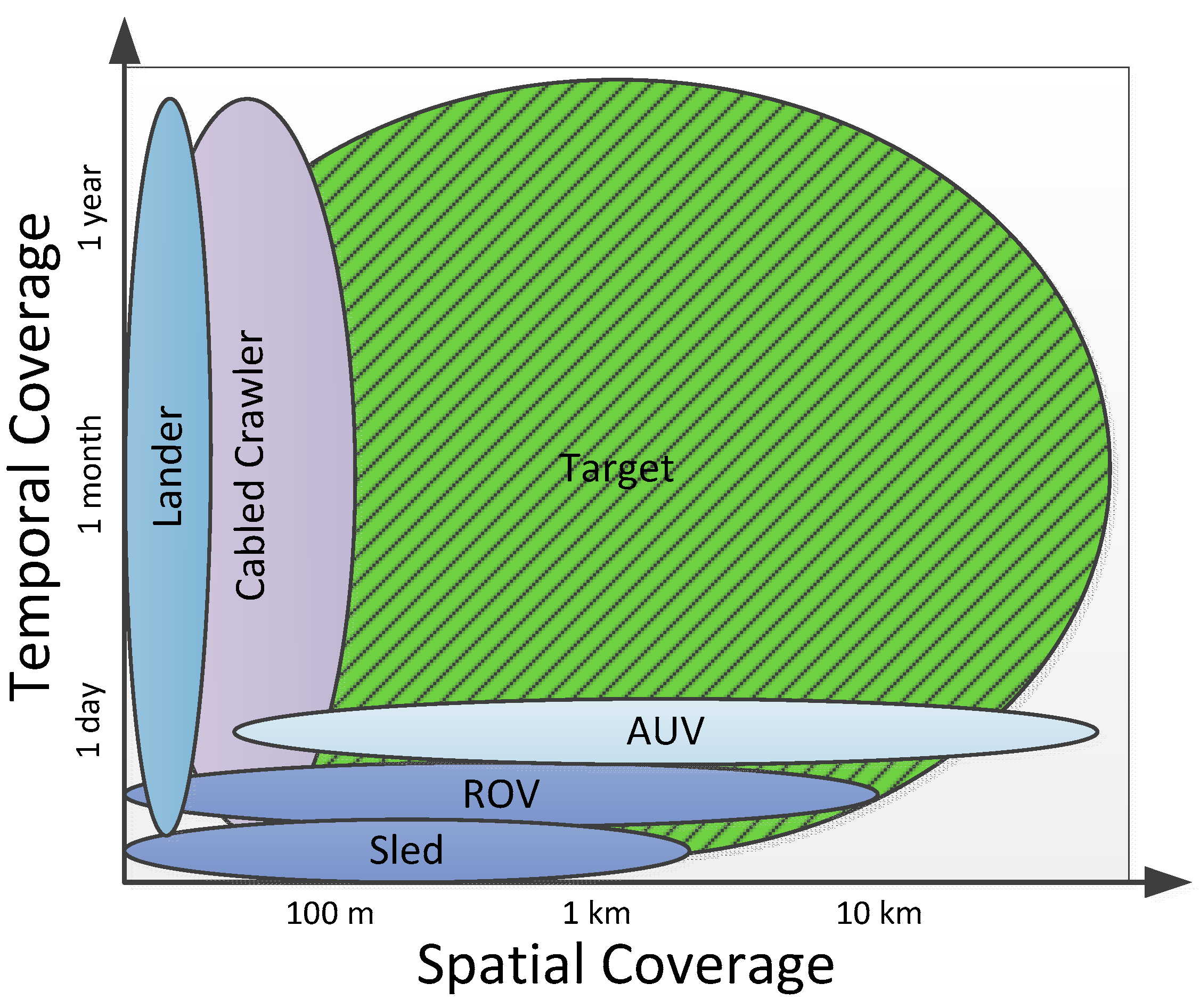
3.1. Improved Spatial and Temporal Resolution

The aim in overcoming the limited storage capacity of benthic sampling devices is to reach higher spatial and temporal resolutions of biodiversity information than is so far feasible. This will allow the answering of important questions on the origin, maintenance and fate of deep-sea biodiversity. For this purpose, a nested design, e.g., consisting of a grid of hexagonal plots, has been proposed, since the equidistant nature between a maximum of samples minimizes statistical bias due to spatial autocorrelation and can, thus, provide results being representative for a defined area. Such a design, however, can easily exceed a sample size of 100 samples [50], (constraints [23]). If such a standardized sampling design is applied to different deep-sea regions of the world and true faunistic comparisons are feasible, it would be possible to decipher the colonization and evolution of all size classes of organisms in the deep-sea. Such a sampling design could uncover whether the deep-sea is a source of species that originated in this environment in situ or whether species colonized the deep from the adjacent slopes [51]. It could also help to answer the question of whether a long-term biodiversity-productivity relationship exists in a generally highly food-limited deep-sea system [52]. Moreover, the responses of the fauna, for example by elasipod holothurians, to short-term food-flux events to the seafloor (e.g., [53]) could be monitored. Such a sampling design would also uncover species turnover, as well as the degree of isolation of stations or deep-sea basins. The present-day numbers of deep-sea samples and their limited spatial coverage hampers our understanding of patterns and processes in this vast environment [54]. However, not only the spatial, but also the temporal resolution in deep-sea biodiversity could be very much improved. Since the introduction of time-lapse cameras to deep-sea research, we know that some ecological processes are more variable in space and time (and operate on swifter timescales) than was anticipated. Such processes include the discrete food input to the seafloor events and its subsequent consumption by grazers, of food falls attracting a succession of representatives of various feeding types, including scavengers (for a new technical development, see [55,56]). For such applications, event-triggered cameras can be used to better record these ongoing and unpredictable processes. A larger spatial and, alternatively, temporal coverage and resolution of the availability of food for grazers could be achieved by applying the hyperspectral imaging method [57]. It might be necessary to modify the existing “Hypersub” system developed for studies on microphytobenthos in intertidal habitats to lander- or crawler-based deep-sea applications focusing on phytodetritus. Vents and seeps exhibit a very fragile and variable nature in physical conditions, but also in regard to the origin, climax and extinction of the outflow of gas. In general, the behavior of any mobile epifauna and megafauna could be studied comprehensively and in detail by event-triggered camera systems. All such observations could contribute to a much better understanding of the functioning of the deep-sea ecosystem, which is essential for an efficient conservation planning and management in a time of increasing exploitation of natural and mineral resources.
A higher efficiency of direct observations could be obtained if the area covered by a camera system could be enlarged without reducing optical resolution. This would demand the development of new photo-sensor chips in combination with a better illumination of the seabed. The problem of how to best cover a larger area can also be addressed by camera systems scanning the sea floor. The main problem with these systems, however, is still water diffraction, which cannot yet easily be overcome by technology. Another advance in the efficiency of imaging systems for investigating seafloor fauna is not necessarily linked to the in situ deployments. Approaches using semi- or completely automatic analyses of image data are still in their infancy and face problems of false species identification, especially of organisms with a non-unique shape [56,58,59]. Computer-aided image processing can help to measure the size of single key organisms and the velocity of their movements or aspects of their physiological performance, such as the physical, observable “pumping” of filter feeders. It can also provide new insights into the benthic ecosystem of the deep-sea, when 3D images are provided, which allow the observer to study single specimens and species associations from any angle and at any chosen distance.
GOOS (Global Ocean Observing System) including DOOS (Deep Ocean Observing Strategy) is a permanent global system for observations, modeling and analysis of marine and ocean variables to support operational ocean services worldwide (http://www.ioc-goos.org/). Development of improved spatial and temporal monitoring of species and efficient, long-term observations of the environment of the Southern Ocean ecosystems is a priority of the Southern Ocean Observing System (SOOS; http://www.soos.aq/). All of these observation systems have used mainly physical parameters or phytodetritus availability at the deep-sea floor; however, monitoring of all size classes (meiofauna, protists, microbes) of deep-sea ecosystems at different spatial and temporal scales are to date lacking. In the following chapter, we hypothesize a process of eliminating sampling limitations and pave the way for necessary developments of gear for the next decades.

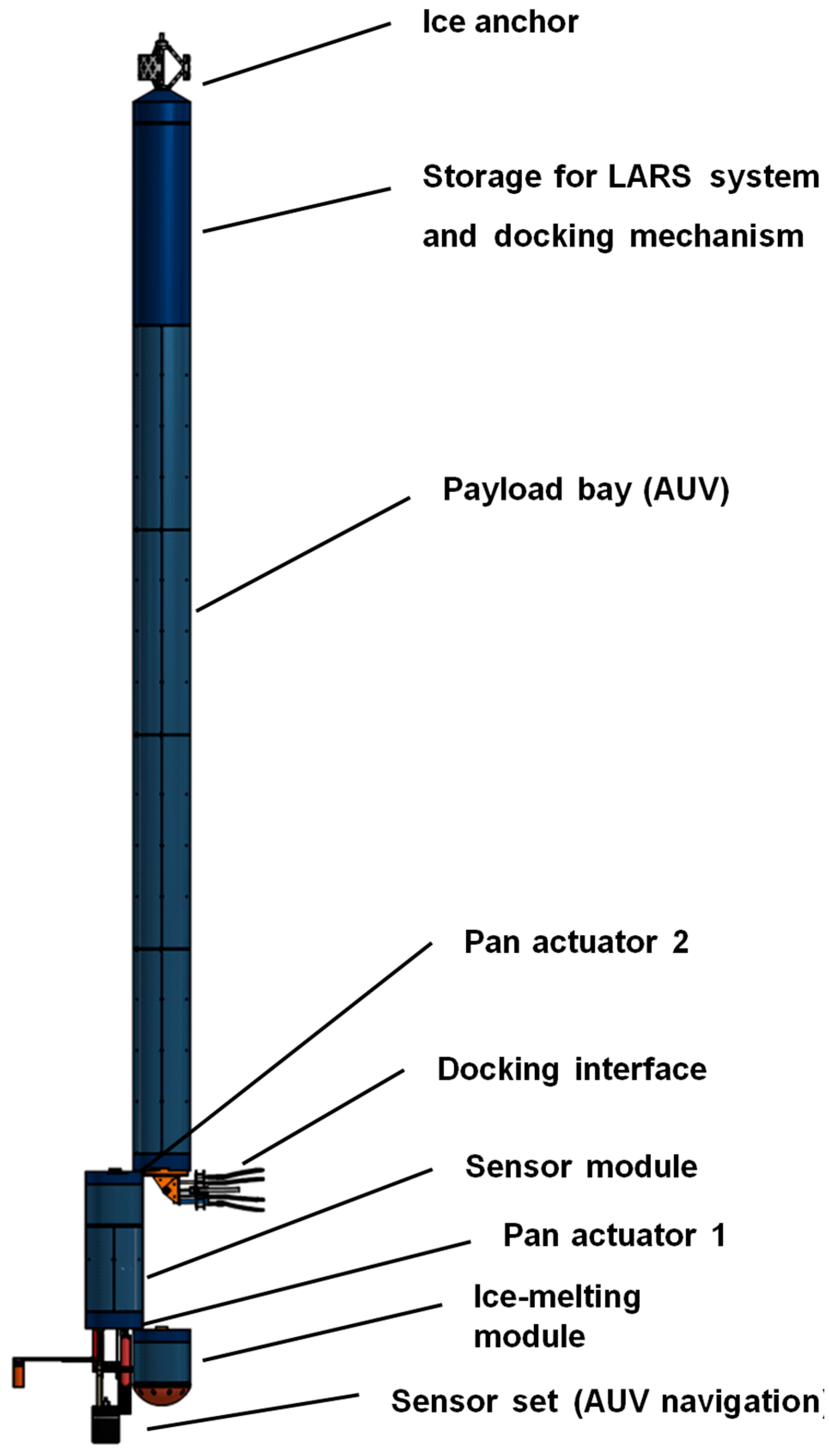
3.2. Increased Autonomy, Deployment Independent from a Deep-Sea Wire

Here, we propose to solve the problem of limitation by developing novel marine sampling technology, combining traditional and new approaches (Figure 7), which besides intermediate financial requirements, demands an estimated time span of five to 15 years of development. The sampling concept is generally applicable to all size fractions of biological samples ranging from microbes to macrobenthos to all feeding types and selected environmental parameters The aim is to exceed the actual frequency of currently collected samples many times or even by orders of magnitudes, which is demanded by many biodiversity research approaches. Such progress cannot be reached by increasing numbers of deployments of currently-used standard sampling devices because of the principally limited ship’s time. The underwater sampling platform could be an intermediate-sized untethered crawler to be deployed and recovered from a research vessel. It preferably fulfills an a priori programmed mission carried out autonomously by automatic propulsion over a defined period of time and pre-defined area, e.g., sediment cores in the above-mentioned sampling design or simply randomly along a straight line. The crawler should be programed to take samples with corers or suckers at pre-defined locations. To allow sampling at a relatively high number of such locations, the volume of such samples must be reduced in volume immediately after the catch to the necessary minimum, especially in the case of large macrobenthic organisms. This is required especially in the case of the macrobenthos comprising the infauna, ranging from large nematodes to polychaetes, and the mobile hyperbenthic fraction, such as crustaceans. Thus, the samples must be washed or sieved in situ and cleaned from the sediments immediately after the catch. For the larger epibenthos, like sponges or holothurians, we propose a selective sampling. Videos and stills of the sampling procedure will be recorded to check during the data analysis a correct treatment of the sample. Based on a program-controlled decision, the entire specimen will be sampled or pieces of a large specimen are to be taken, e.g., a piece can be cut off or punched out. Such an operation demands a decision by the computer system of which cutting tool is to be used. Even the option must be considered to carry out non-invasive in situ DNA analyses by touching the skin as soon as such technology is principally developed. Videos and stills of the sampling procedure will be recorded to check a correct treatment of the sample later. Both types of samples, the non-selective eventually cleaned and the selected material can be further treated in either of two ways. Firstly, they may be preserved and stored in separate containers until the entire platform is recovered, in which case the storage capacity would be the major limiting factor for the entire operation of the crawler. Secondly, the samples may be genetically analyzed by an in situ lab to identify all species sampled; after discarding the sample “only”, digital genetic and environmental data, as well as images would be stored. Similarly to the biological samples, biogeochemical parameters of the bottom-near water layer and of the sediment can be analyzed. Both data and reference samples can be released from the platform to the sea surface in containers, eventually triggered by the research vessel being ready to recover them. If only data and not true samples are collected from in situ analyses and the data storage medium is released to the sea surface, data could be transmitted through satellites independently of the ships’ operation. Such an approach would allow long-term operations, which are not limited by the storage capacity, and the risk of losing data is minimized. A further step of development should expand the in situ analyses of samples, which would allow the study of aspects of functional diversity, e.g., those related to feeding preferences and reproduction biology. Such missions demand totally new technical approaches, such as automatic dissection of individuals, as well as recording, automatic microscopy and additional biochemical analyses, such as isotope and C:N analyses. Even if not all of these applications can be realized within the next years, it is urgently necessary to pave the way now for difficult developments over the next decades.

3.3. In Situ Genomic and Metagenomic Analyses

Deep-sea sediments contain large amounts of DNA that represent a molecular repository for all groups of organisms living in the open ocean. The concentration of DNA at the deep-sea floor can be very high, reaching 0.3 g·m−2 [60,61]. The stable abiotic conditions at the deep-sea bottom, including low temperature, great pressure and small disturbance, enhance DNA preservation [62]. The eukaryotic DNA recovered from the subsurface deep-sea sediment samples was dated back to 32.5 ka in the case of abyssal plains in the South Atlantic [63] and 125 ka in the eastern Mediterranean sapropels [64].
Environmental DNA (eDNA) present in the marine sediments is either extracellular, i.e., consisting of free molecules attached to the clay or sand grains, or intracellular, originating from living microbial or meiofauna-sized organisms, cell debris, tissue fragments, cysts or eggs [65]. The eDNA surveys of deep-sea eukaryotic diversity show that up to 50% of DNA sequences may come from species living in the water column [66]. The eDNA was extensively used to explore the phylogenetic diversity of deep-sea microbial species [8,67,68,69] and to study their distribution at micro- [70] or macro-spatial levels [71]. The eDNA was also used to assess the environmental impact of the Deep Water Horizon oil spill on deep-sea microbial and meiofaunal communities [72].
Until now, all deep-sea eDNA surveys have been based on analyses of sediment samples processed on deck. However, rapid development of molecular techniques prompts the search for “eco-genomic sensors” that would allow the detection and analysis of the genetic diversity in situ [73,74]. A Deep-water Environmental Sensor Processor (D-ESP) was successfully deployed for in situ quantitative PCR detection of methanotrophic bacterial species in a methane-rich mound in the Santa Monica Basin [75]. The advantage of autonomous systems, such as D-ESP, is to provide information about the presence and abundance of particular species or genes in real time. The D-ESP was developed for analyzing particles in filtered seawater, and a similar system could possibly detect the presence of sediment-dwelling species in situ. Very useful would be the development of devices that would allow preserving eDNA directly at the bottom of the sea, in order to avoid its degradation during the long transportation of the samples from the abyssal depths to the surface.
Single components of the proposed technical and scientific concepts are already available and are successfully used for different purposes in marine or terrestrial research. Others resemble concepts developed to find and analyze extra-terrestrial life on the surface or in sub-glacial habitats of other planets and their moons. The exchange of experiences on their reliability of the development and application of similar technology in different environments can be of benefit for both purposes.

4. Applicable Technologies from Robotics

4.1. Mobility

A key requirement for allowing larger spatial coverage for sampling is the ability to have mobility of the sampling device and the support infrastructure. One important aspect in this context is that the vehicle is self-propelled and independent of a ship. The mobility technology can take a number of forms depending on the location and role of the vehicle. It is necessary to differentiate between mobility on the surface, in the water column and on the seafloor.
Sea surface mobility for autonomous operations is important for providing access to communication devices (e.g., satellites) and renewable power sources, like solar power. Classical mobility concepts like boats can also be used on the surface. However, fully-self-sufficient mobility based on external power sources is not always feasible, depending on water current and sea state. An interesting concept is the use of wave power for propelling and station keeping wave gliders [76], which have the ability to travel anywhere on the water surface while producing a surplus of power.
Mobility in the water column is largely dominated by the mature technologies of self-propelled vehicles. The shape of the hull is quite important in this respect, as the water resistance has a huge impact on the efficiency of the system. Vehicles are normally either optimized for efficiency and speed or maneuverability. The faster systems require a forward velocity in order to steer and, thus, have difficulties in holding a specific position or travelling slowly. Hovering-type systems are able to do this, but are much less energy efficient; in recent years, a number of systems have emerged that do not use rotating propellers. Gliders change their buoyancy and use their aquadynamic properties to gain forward motion [77], while certain bio-inspired systems mimic the locomotion of fish [78].
While mobility in the water column can operate in all three dimensions, mobility on the seafloor is limited to two. The advantage of keeping to the seafloor is that a force transfer with the ground makes it much easier to hold a specific position, even when exposed to strong currents or also to be able to completely switch off the system to conserve power. For benthic research, precise sampling has to be performed, which is only possible when in direct contact with the sediment. The modes of locomotion can be transferred from terrestrial applications. There are examples for wheeled [79], tracked [44], legged [80] or leg-wheel hybrid systems [81].

4.2. Navigation–Bathymetry, Mapping

Underwater localization can be categorized by the type of sensor used. Three main types are common: dead-reckoning, acoustic localization and visual localization.

4.2.1. Dead-Reckoning

Dead reckoning is a method for localization that only relies on vehicle-internal sensors. Classical dead-reckoning uses time measurement, the vehicle’s orientation and an estimate of speed to calculate a vehicle’s current position. While time and orientation can be measured easily enough (compass or AHRS), vehicle speed is more complicated and usually estimated using a Pitot-tube, which measures the vehicle’s speed relative to its surrounding water [82].

4.2.2. Acoustic Localization

Acoustic localization can be considered the current standard in underwater robotics. In addition to the basic dead-reckoning senor as described above, a DVL sensor is included. A DVL measures speed over ground by measurement of the Doppler shift of an acoustic signal, which bounces off the sea floor. Properly used, this can provide a very good estimate of speed-over-ground for the dead-reckoning filter, resulting in an acoustic dead-reckoning. The drawback of this approach is the necessity to remain in proximity to the sea floor, since a DVL does not have unlimited range (usually 10 to 500 meters, depending on the device). While usually more stable than pure dead-reckoning, the restriction of un-bound long-term error is still relevant. In order to remedy this, beacon-based localization is included in the localization setup. A beacon-based localization device uses triangulation to measure the position of a mobile transponder relative to three or more stationary transponders (respectively, one stationary transponder for Ultra-Short Base-Line (USBL)). Depending on the distance of the stationary transponders, these systems are called LBL, SBL or USBL systems (Long Base-Line, Short Base-Line or Ultra-Short Base-Line). The individual techniques differ mostly in complexity of set-up and accuracy [83,84]. While requiring prior setup and line-of-sight during missions, these systems provide drift-free localization information. This information is usually less accurate than necessary for precision missions, but it is accurate enough to provide an upper bound for the long-term error when used in conjunction with a (acoustic) dead-reckoning system.

4.2.3. Visual Localization

In visual underwater localization, a camera system provides localization data. These data can be either used as the sole source for localization or in combination with dead-reckoning or acoustic data. Most important is SLAM, where an upper boundary to the localization error is maintained by recognizing previously-surveyed areas.
Eustice [85] described underwater-visual navigation and introduced the concept of VAN (Visually-Aided Navigation). In this approach, the camera attached to the AUV helps to improve its navigation capabilities.
Mahon et al. [86] describe a VAN-based approach using a stereo-vision system for loop closure hypothesis formation and matching in a post-processing approach. Richmond [87] describes an approach for navigation and mosaicking; however, most information for the localization originates from vehicle sensors, like DVL and FOG.

4.3. Autonomous Systems

Most currently-deployed autonomous systems (AUVs, autonomous benthic crawlers) can independently execute a single mission, but will then be retrieved, recharged and re-programmed manually. For a persistent autonomy scenario, all of these tasks will have to be executed autonomously, as well. With current technology, this requires a docking-station (no long-term energy system available, no broadband communication for underwater scenarios available). For such a mission, the behavior of the system needs to be reliable additionally to the navigation system. When a problem occurs that may hinder or prevent the autonomous system from returning to the docking station, the device must decide on its own how to handle this situation without the possibility of human intervention. This is an important difference to robotic missions on Mars, for example, where there is the possibility for humans to intervene at least via (delayed) radio communication when a problem occurs.
For a practical long-term autonomous system, this would only be possible while it is physically connected to the docking station. Therefore, the system must always be able to find a way to return to the docking station, to upload the data collected, which would otherwise be lost, and possibly ask a human for help. This requires a constant monitoring of system states, actuator commands and sensor values to detect anomalies or faults in the first place. The handling of the detected problem could then be done depending on the kind of problem either with predefined solutions (e.g., using other sensors to compensate for a faulty one) or using learning algorithms [88].

4.4. Sensor Processing

The automatic processing of sensor readings is an important aspect for performing autonomous operations for benthic research. This is for two reasons: (1) many of the sensors, such as cameras, produce a large amount of data, and recording this data in high resolution over the timespan of years might not be feasible; (2) when performing sampling operations, usually the amount of samples that can be taken is limited; areas or objects worth sampling need to be identified.
A number of activities have been researched in the area of image processing, pattern recognition and AI (Artificial Intelligence). Especially in the area of space robotics, autonomous science has extensive previous work with running examples on Mars rovers [89], and transfer potential to the underwater area [90].

4.5. Manipulation: Sampling

In order to perform sampling operations or to handle samples or sensor deployment, manipulation capabilities are required. The current state of the art in underwater manipulation is mainly focused on heavy-duty operations with hydraulic arms and end effectors. These manipulators are likely not suitable, and there is a need for electric manipulators with finer position and force control. The end effectors are also very important, when it comes to sampling or general handling of underwater structures. Current manipulator systems installed on ROVs, for example, only provide visual feedback and simple position-based automation. This is problematic when handling macrofauna or when work is performed under low visibility conditions. New concepts for haptic feedback manipulation devices [91] are interesting prospects, and force-controlled manipulation is already state of the art in terrestrial robotics.

4.6. Energy Supply

For long-term deployment of ship-independent systems, the question of energy supply arises. In principle, batteries can be used for a large number of applications. Current lithium polymer cells have an energy density of up to 200 Wh/kg. However, larger batteries increase the size and cost of the device and provide additional logistical challenges due to safety regulations. Looking for additional sources of energy is vital for continuous long-term operation. Fuel cells provide one way to improve the power density for larger systems, but ultimately have similar problems to batteries. A reliable source of power is on the surface in the form of solar power. Wind and wave power are also a viable option, but in the area of electric power generation, solar is a more mature technology and easier to handle, especially in the absence of moored structures. Most power sources that can be extracted from the water column, such as the utilization of temperature gradients in black smokers, are mostly local in scope and difficult to harvest. Transporting solar power down to the seafloor mirrors the way the ecosystem is transporting energy to the seafloor.

4.7. Swarm Systems

While mobile autonomous systems already provide the possibility to cover larger areas for sampling, they are still punctual in terms of sampling density. For dense sampling of water column and benthic processes, robot swarms could provide a technical solution. Small and inexpensive sensors could be deployed to perform monitoring and sampling of large areas simultaneously. In this way, biological processes could be tracked more precisely at spatial scales. To make swarm systems economical, small and inexpensive systems must be used, possibly functional 3D printing could be a promising area for future advances in this field. Small systems with, e.g., lab on chip sensors would be able to perform dense sampling of large areas. However, while the prospect sounds promising, there are a number of challenges to tackle before swarm systems are viable. Energy supply is much more critical for smaller systems and infrastructure components, such as communication and processing, need to be multiplied between the systems. Ecological aspects should also be taken into account. For example, littering the seas with robot probes is likely not a sustainable solution. Research is urgently needed to improve the applicability of underwater swarms to monitoring and sampling.

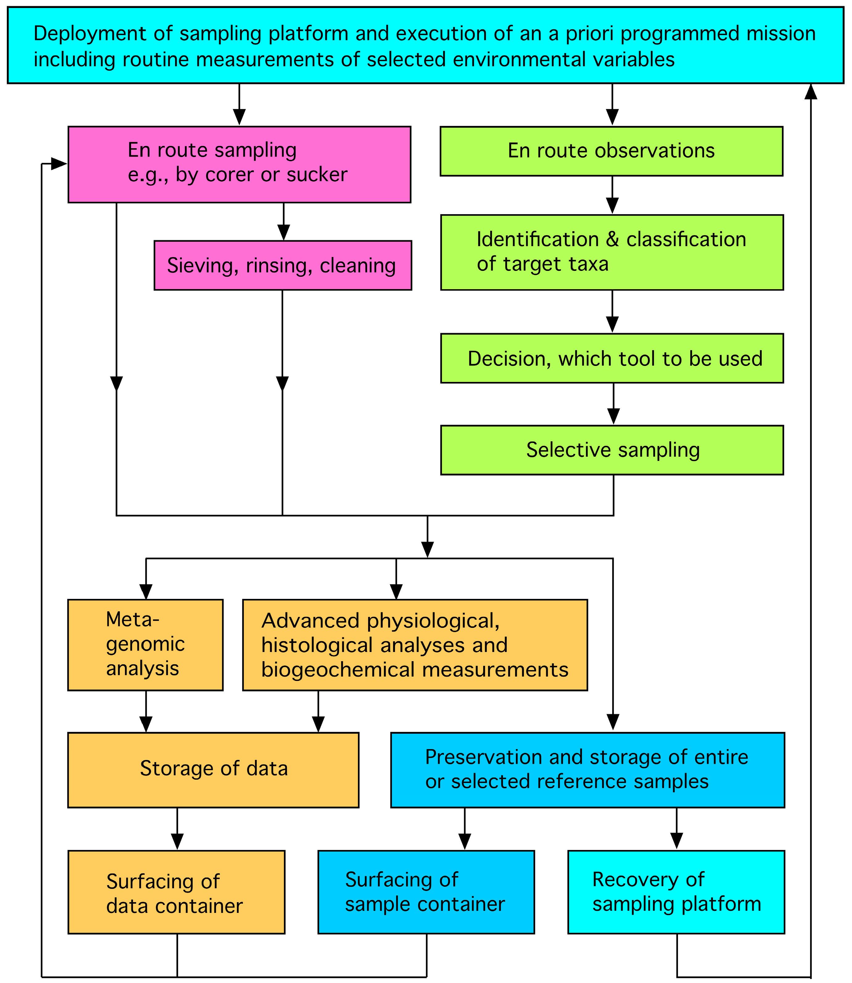
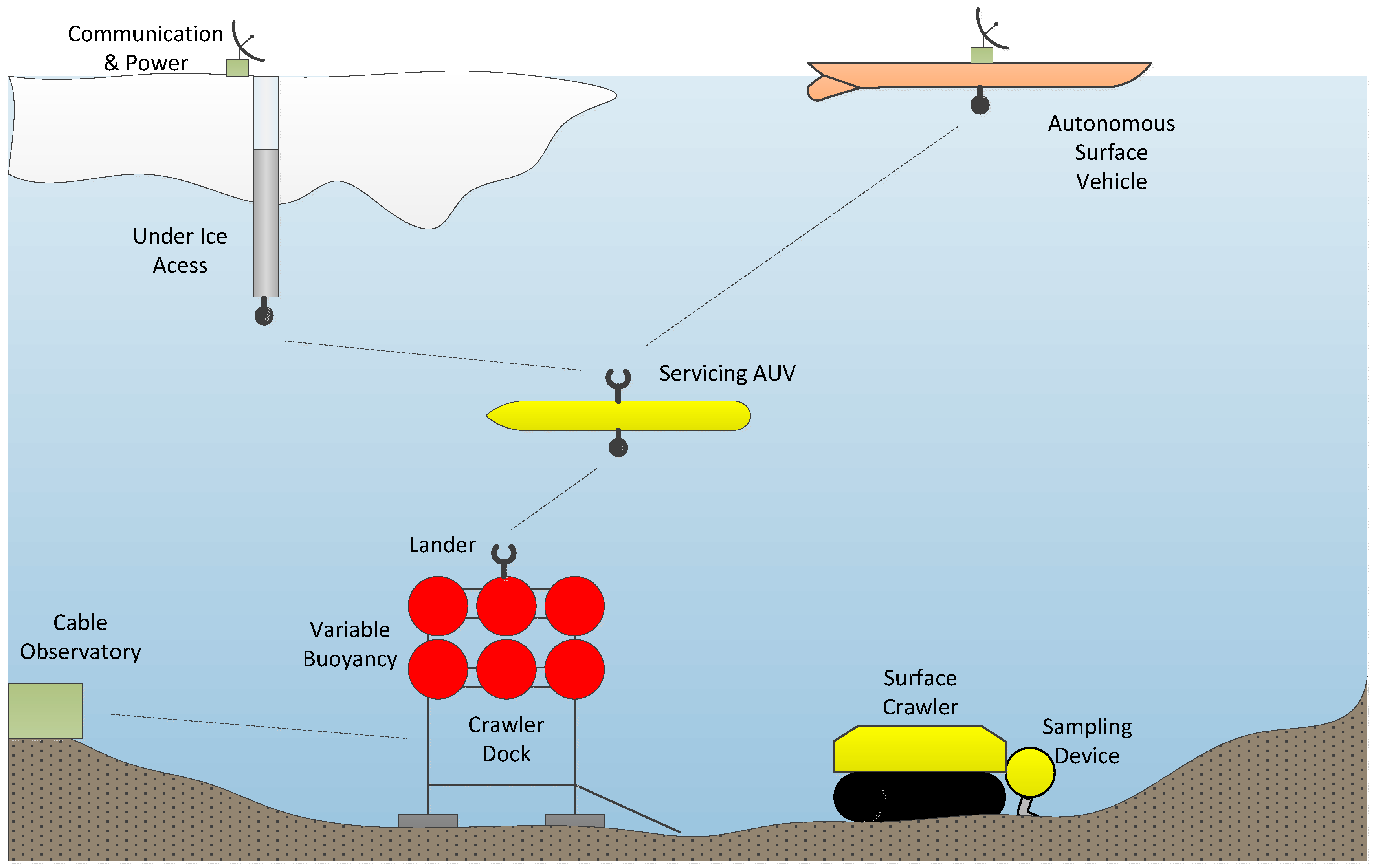
5. Vision: Real-Time Monitoring, In Situ Science

How a future real-time monitoring, in situ science system could look is presented in the following scenario (Figure 8). The objective is to explore and monitor an area that is difficult to access with minimal intervention and external control. The proposed system would consist of three components: a platform at the seafloor (lander) with a sampling and analysis system, an AUV ensuring the exploration and transport and a station with surface access.
The lander has a number of special requirements for integration into the system: besides the ability to sample and analyze, it also needs to be able to act as a docking station for a crawler system and the exploration AUV. For the latter purpose, a docking adapter is mounted on top, which enables the AUV to find the lander, dock with it and transfer data and energy. A variable-buoyancy engine completes the requirements: it needs to be dimensioned so it can render the lander neutrally buoyant for relocating the entire platform.
The AUV is a multi-role vehicle: it needs to be able to localize and dock with the surface station, as well as the lander. It must have an extended energy capacity, as well as navigation (USBL, IMU, DVL, cameras) and analyses sensors (cameras, dissolved oxygen, CTD, water sampling and analysis). The surface station should be able to provide power and communication through a docking interface, and be able to communicate with the involved scientists.
While the surface-based elements can use GPS for navigation, long-range navigation of the submerged elements is performed using dead-reckoning and can be aided by water current profilers. Mid-range navigation for homing of the mobile systems is performed with acoustic devices, which are used on both mobile and stationary parts of setup. Close-range navigation and docking will likely require the precision of imaging systems.
In the scenario, all three systems are manually deployed. After successful deployment, the AUV downloads its first mission and detaches from the surface station, starting to explore the environment. If the batteries run low, it returns to the surface station in order to recharge and store its collected data. Successively, a map of the environment is created, and more directed (water) sampling and analyses can be triggered by the involved scientists through adaptation of the mission profiles, which are then downloaded to the AUV at the next docking interval.
After deployment, the lander starts sampling the current location, processing the material and “digitizing” its findings. It continues until either its battery runs low or all required information is gained. As soon as this happens, it starts signaling on a low-bandwidth acoustic channel (to either the AUV or the surface station). The AUV will respond and dock with the lander. It can now exchange information and decide what to do: transport the lander’s findings to the surface station for further analysis by the involved scientists, re-charge the lander or move the lander, including the attached crawler system. Moving the lander involves triggering its variable buoyancy engine, making the lander neutrally buoyant. This way, it can easily be lifted by the AUV and transported to a new location. If a re-charge is necessary, the AUV transfers as much energy to the lander as possible while maintaining enough charge to return to the surface station. In this scenario, the only in situ human intervention is necessary in the initial deployment until maintenance, meaning that the exploration is carried out by robotic agents, which only need updated missions as input and which provide valuable scientific information as output.
To illustrate the versatility of this approach, two different surface stations are described, which both have their special application scenario, but integrate seamlessly into the system. The two scenarios are: under-ice and open water operations.
In the under-ice scenario, the aim is a survey of the continental shelf and the grounding line below the Antarctic ice shelf. The surface-station consists of a topside station, which stays on the ice and is connected to a power generator and a communication array. From this topside station, an ice-shuttle system is deployed, which can autonomously melt a hole into the ice. It is connected by cable with the topside station, which provides power and communication. After liquid water is reached, the ice-shuttle fixes itself in the ice-hole using an anchoring system. The melting-head is swiveled to the side, and an exploration AUV is pushed out of the ice-shuttle with a docking system. Finally, a set of navigation sensors is deployed from the ice-shuttle.

Technological Challenges

Many of the technology parts that are described in the scenario are already available as standalone systems. Self-reliant and autonomous ASV, like the WaveGlider, are commercially available. Surface crawlers are a tested and proven technology. Additionally, landers have been around for many years. Under-ice systems are in development and likely to become available soon.
The key technological challenges are in the interfacing and long-term reliability.
Interfacing includes both the electromechanical interfaces, which physically connect the devices, as well as the navigation and docking logic, that allows meeting the close constraints of physical docking. Interfaces need to provide a mechanical connection, data communication and power transfer.
Long-term reliability is something that is another key aspect of the proposed system. Especially in such complex systems, that run over a long time, this can be a very challenging problem. Space engineering provides well-proven templates for reliability engineering in robotics. Redundancy plays a vital role in improving the overall reliability figure. Proper fault handling is another aspect that has to be taken into consideration.

6. Conclusions

Modern research vessels are equipped with navigation systems that allow deployment of gear of all sizes and weight classes. Besides working with cables, autonomous gear can be deployed and retrieved from most research vessels. Operations that require the deployment via cables are logistically difficult, progressively time and cost intensive with increasing deployment depth. In the deep-sea, at abyssal or hadal depths, operations for obtaining macrobenthic samples (or samples with smaller size fractions) that allow biodiversity or community analyses still depend on trawl gear of similar design and deployment methodology to that used in the early days of deep-sea research. Therefore, we advocate strongly for investment into the development of modern research equipment for biological benthic sampling. A variety of technological advancements derived from robotics are today in place and could be used that do not necessitate a cable connection to the research vessel (cut the umbilical). We recommend the development of autonomous systems with high mobility for navigation, which would not only be able to map and photograph the seafloor, but also to take biogeochemical, biological and genetic samples simultaneously. Besides the time-saving aspect, the synoptic observation and sampling would increase comparability and standardization between missions and research cruises and would help to better explain patterns and processes, as well as ecosystem functioning, which are prerequisites for ecosystem services. It is anticipated that the investment into the development of such a modern autonomous deep-sea sampler would pay off after approximately ten expeditions with a large and modern research vessel.

Acknowledgments

We thank the German Federal Ministry of Economics and Technology (BMWi) for the grant No. 50NA1217. Autun Purser is thanked for reading and correcting the English language. The paper was also partially funded by the Helmholtz Alliance ‘‘Robotic Exploration of Extreme Environments (ROBEX)’’ project.

Author Contributions

Angelika Brandt, Julian Gutt, Marc Hildebrandt, Jan Pawlowski, Jakob Schwendner, Thomas Soltwedel and Laurenz Thomsen designed and wrote the manuscript, the coordination and most of the writing was done by Angelika Brandt. Julian Gutt contributed especially to chapter 3, but also helped with many other paragraphs. Thomas Soltwedel helped especially for AUV and ROVs, and Laurenz Thomsen for the crawler system. Jan pawlowski write the part on genetic tools and Jakob Schwendner and Marc Hildebrandt added the paragraphs on engineering aspects and future potential developments, information provided especially in chapters 4 and 5.

Conflicts of Interest

The authors declare no conflict of interest.

References

  1. Witte, U.; Wenzhöfer, F.; Sommer, S.; Boetius, A.; Heinz, P.; Aberle, N.; Sand, M.; Cremer, A.; Abraham, W.-R.; Jørgensen, B.B.; et al. In-situ experimental evidence of the fate of a phytodetritus pulse at the abyssal sea floor. Nature 2003, 424, 763–766. [Google Scholar] [CrossRef] [PubMed]
  2. Ebbe, B.; Billett, D.S.M.; Brandt, A.; Ellingsen, K.; Glover, A.; Keller, S.; Malyutina, M.; Martinez Arbizu, P.; Molodtsova, T.; Rex, M.; et al. Diversity of abyssal marine life. In Life in the World’s Oceans; McIntyre, A.D., Ed.; Blackwell Publishing Ltd.: Oxford, UK, 2010; Chapter 8; p. 361. [Google Scholar]
  3. Mora, C.; Tittensor, D.P.; Adl, S.; Simpson, A.G.B.; Worm, B. How many species are there on earth and in the ocean? PLoS Biol. 2011, 9, 1–8. [Google Scholar] [CrossRef] [PubMed]
  4. Rex, M.A.; Etter, R.J. Deep-Sea Biodiversity. Pattern and Scale; Harvard University Press: Cambridge, MA, USA; London, UK, 2010. [Google Scholar]
  5. McClain, C.R.; Schlacher, T.A. On some hypotheses of diversity of animal life at great depths on the sea floor. Mar. Ecol. 2015, 36, 849–872. [Google Scholar] [CrossRef]
  6. Danovaro, R.; Snelgrove, P.V.; Tyler, P. Challenging the paradigms of deep-sea ecology. Trends Ecol. Evol. 2014, 29, 465–475. [Google Scholar] [CrossRef] [PubMed]
  7. Brandt, A.; Gooday, A.J.; Brix, S.B.; Brökeland, W.; Cedhagen, T.; Choudhury, M.; Cornelius, N.; Danis, B.; De Mesel, I.; Diaz, R.J.; et al. The Southern Ocean deep sea: First insights into biodiversity and biogeography. Nature 2007, 447, 307–311. [Google Scholar] [CrossRef] [PubMed]
  8. Corinaldesi, C. New perspectives in benthic deep-sea microbialecology. Front. Mar. Sci. 2015, 2, 1–12. [Google Scholar] [CrossRef]
  9. VanDover, C.L.; Aronson, J.; Pendleton, L.; Smith, S.; Arnaud-Haond, S.; Moreno-Mateos, D.; Barbier, E.; Billett, D.; Bowers, K.; Danovaro, R.; et al. Ecological restoration in the deep sea: Desiderata. Mar. Policy 2014, 44, 98–106. [Google Scholar] [CrossRef]
  10. Bruun, A.F. Animal life of the deep-sea bottom. In The Galathea Deep Sea Expedition 1950–1952; Bruun, A.F., Greve, S., Mielche, H., Spärk, R., Eds.; George, Allen and Unwin: London, UK, 1956; pp. 149–195. [Google Scholar]
  11. Belyaev, G. Deep-Sea Ocean Trenches and Their Fauna; Nauka: Moscow, Russia, 1989. [Google Scholar]
  12. Eleftheriou, A.; McIntyre, A.D. Methods for the Study of the Marine Benthos, 4th ed.; Eleftheriou, A., Ed.; John Wiley & Sons, Ltd.: New York, NY, USA, 2013; pp. 1–465. [Google Scholar]
  13. Sanders, H.L.; Hessler, R.R.; Hampson, G.R. An introduction to the study of deep-sea benthic faunal assemblages along the Gay Head-Bermuda transect. Deep-Sea Res. Part II 1965, 12, 845–867. [Google Scholar] [CrossRef]
  14. Hessler, R.R.; Sanders, H.L. Faunal diversity in the deep-sea. Deep-Sea Res. 1967, 14, 65–78. [Google Scholar] [CrossRef]
  15. Brandt, A.; Barthel, D. An improved supra- and epibenthic sledge for catching Peracarida (Crustacea, Malacostraca). Ophelia 1995, 43, 15–23. [Google Scholar] [CrossRef]
  16. Brenke, N. An epibenthic sledge for operations on marine soft bottom and bedrock. Mar. Technol. Soc. J. 2005, 39, 10–21. [Google Scholar] [CrossRef]
  17. Brandt, A.; Elsner, N.; Golovan, O.; Malyutina, M.V.; Riehl, T.; Schwabe, E.; Würzberg, L.; Brenke, N. Epifauna of the sea of Japan collected via a new epibenthic sledge equipped with camera and environmental sensor systems. Deep-Sea Res. Part II 2013, 86–87, 43–55. [Google Scholar] [CrossRef]
  18. Brandt, A.; Elsner, N.; Brenke, N.; Golovan, O.A.; Lavrenteva, A.V.; Malyutina, M.V.; Riehl, T. Abyssal macrofauna of the Kuril-Kamchatka Trench area collected by means of a camera-epibenthic sledge (Northwest Pacific). Deep-Sea Res. Part II 2015, 111, 175–188. [Google Scholar] [CrossRef]
  19. Brandt, A.; University of Hamburg, Hamburg, Germany. Personal communication, 2016.
  20. Wolff, T. The systematics and biology of bathyal and abyssal Isopoda Asellota. Galathea Rep. 1962, 6, 1–320. [Google Scholar]
  21. Wolff, T. Isopoda from depths exceeding 6000 m. Galathea Rep. 1956, 2, 85–157. [Google Scholar]
  22. Jamieson, A. The Hadal Zone: Life in the Deepest Oceans; Oxford University Press: Oxford, UK, 2015; pp. 1–372. [Google Scholar]
  23. Underwood, A.J.; Chapman, M.G. Design and analysis in benthic surveys in environmental sampling. In Methods for the Study of the Marine Benthos, 4th ed.; Eleftheriou, A., McIntyre, A.D., Eds.; John Wiley & Sons, Ltd.: New York, NY, USA, 2013; Chapter 1. [Google Scholar]
  24. Grassle, J.F.; Sanders, H.L.; Hessler, R.R.; Rowe, G.T.; McLellan, T. Pattern and zonation: A study of the bathyal megafauna using the research submersible Alvin. Deep Sea Res. Oceanogr. Abstr. 1975, 22, 457–462. [Google Scholar] [CrossRef]
  25. Rex, M.A. Community structure in the deep-sea benthos. Annu. Rev. Ecol. Syst. 1981, 12, 331–353. [Google Scholar] [CrossRef]
  26. Grassle, J.F.; Maciolek, N. Deep-Sea species richness: Regional and local diversity estimates from quantitative bottom samples. Am. Nat. 1992, 139, 313–341. [Google Scholar] [CrossRef]
  27. Brattegard, T.; Fosså, J.H. Replicability of an epibenthic sampler. J. Mar. Biol. Assoc. UK 1991, 71, 153–166. [Google Scholar] [CrossRef]
  28. Riehl, T.; Brenke, N.; Brix, S.B.; Driskell, A.; Kaiser, S.; Brandt, A. Field and laboratory methods for DNA studies on deep-sea isopod crustaceans. Pol. Polar Res. 2014, 35, 203–224. [Google Scholar] [CrossRef]
  29. Sessions, M.H.; Isaacs, J.D.; Schwartzlose, R.A. A camera system for the observation of deep-sea marine life. In Proceedings of the SPIE 0012, Underwater Photo-Optical Instrumentation Applications II, San Diego, CA, USA, August 1968. [CrossRef]
  30. Fernandes, P.G. Visual surveys can reveal rather different ‘pictures’ of fish densities: Comparison of trawl and video camera surveys in the Rockall Bank, NE Atlantic Ocean. Deep-Sea Res. Part I 2015, 95, 67–74. [Google Scholar]
  31. Bett, B.J. Time-lapse photography in the deep sea. Underw. Technol. 2003, 25, 121–127. [Google Scholar] [CrossRef]
  32. Smith, C.J.; Rumor, H. Imaging techniques. In Methods for the Study of the Marine Benthos, 4th ed.; Eleftheriou, A., McIntyre, A.D., Eds.; John Wiley & Sons, Ltd.: New York, NY, USA, 2013; Chapter 3; pp. 97–124. [Google Scholar]
  33. Smith, C.J.; Rumohr, H.; Karakassis, I.; Papadopoulou, K.-N. Analysing the impact of bottom trawls on sedimentary seabeds with sediment profile imagery. J. Exp. Mar. Biol. Ecol. 2003, 285, 479–496. [Google Scholar] [CrossRef]
  34. Ballard, R.D. The MEDEA/JASON remotely operated vehicle system. Deep-Sea Res. Part I 1993, 40, 1673–1687. [Google Scholar] [CrossRef]
  35. Nokin, M. Victor 6000—A deep teleoperated system for scientific research, OCEANS. In Proceedings of the MTS/IEEE Conference, Halifax, NS, Canada, 6–9 October 1997; Volume 1, pp. 167–171.
  36. Cai, M.; Sou, I.M.; Layman, C.; Bingham, B.; Allen, J. Characterization of the acoustic signature of a small remotely operated vehicle for detection. In Proceedings of the OCEANS 2010 MTS/IEEE SEATTLE, Seattle, WA, USA, 20–23 September 2010.
  37. Nokin, M.; Soltwedel, T.; Klages, M. Deployment of the deep-sea ROV VICTOR 6000 from board the German research icebreaker POLARSTERN in polar regions. In Proceedings of the OCEANS 2000 MTS/IEEE Conference and Exhibition, Providence, RI, USA, 11–14 September 2000; Volume 2, pp. 943–947.
  38. Tengberg, A.; de Bovee, F.; Hall, P.; Berelson, W.; Chadwick, D.; Ciceri, G.; Crassous, P.; Devol, A.; Emerson, S.; Gage, J.; et al. Benthic chamber and profiling landers in oceanography—A review of design, technical solutions and functioning. Prog. Oceanogr. 1995, 35, 253–294. [Google Scholar] [CrossRef]
  39. Van Weering, T.C.; De Stigter, H.C.; Balzer, W.; Epping, E.H.; Graf, G.; Hall, I.R.; Thomsen, L. Benthic dynamics and carbon fluxes on the NW European continental margin. Deep Sea Res. Part II Top. Stud. Oceanogr. 2001, 48, 3191–3221. [Google Scholar] [CrossRef]
  40. Linke, P.; Wallmann, K.; Suess, E.; Hensen, C.; Rehder, G. In situ benthic fluxes from an intermittently active mud volcano at the Costa Rica convergent margin. Earth Planet. Sci. Lett. 2005, 235, 79–95. [Google Scholar] [CrossRef] [Green Version]
  41. Balfour, C.A. Cost-effective remote data acquisition and instrumentation management for oceanographic and environmental monitoring applications. J. Oper. Oceanogr. 2012, 5, 41–52. [Google Scholar] [CrossRef]
  42. Thomsen, L.; Purser, A.; Schwendner, J.; Duda, A.; Flogen, S.; Kwasnitschka, T.; Pfannkuche, O.; Wilde, D.; Rosta, R. Temporal and spatial benthic data collection via mobile robots: Present and future applications. In Proceedings of the IEEE OCEANS 2015, Genoa, Genova, 18–21 May 2015; pp. 1–5.
  43. Barnes, C.R.; Best, M.M.R.; Johnson, F.R.; Pautet, L.; Pirenne, B. Challenges, benefits and opportunities in operating cabled ocean observatories: Perspectives from NEPTUNE Canada. IEEE J. Ocean. Eng. 2013, 38, 144–157. [Google Scholar] [CrossRef]
  44. Purser, A.; Thomsen, L.; Barnes, C.; Best, M.; Chapman, R.; Hofbauer, M.; Wagner, H. Temporal and spatial benthic data collection via an internet operated Deep Sea Crawler. Methods Oceanogr. 2013, 5, 1–18. [Google Scholar] [CrossRef]
  45. Thomsen, L.; Barnes, C.; Best, M.; Chapman, R.; Pirenne, B.; Thomsen, R.; Vogt, J. Ocean circulation promotes methane release from gas hydrate outcrops at the NEPTUNE Canada Barkley Canyon node. Geophys. Res. Lett. 2012, 39, L16605. [Google Scholar] [CrossRef]
  46. Roman, C.; Pizarro, O.; Eustice, R.M.; Singh, H. A new autonomous underwater vehicle for imaging research. In Proceedings of the OCEANS 2000 MTS/IEEE Conference and Exhibition, Providence, RI, USA, 11–14 September 2000; pp. 153–156.
  47. Singh, H.; Eustice, R.M.; Roman, C.; Pizarro, O. The SeaBED AUV: A platform for high resolution imaging. In Proceedings of the Unmanned Underwater Vehicle Showcase, Southampton, UK, 25–26 September 2002.
  48. Hildebrandt, M.; Hilljegerdes, J. Design of a versatile AUV for high precision visual mapping and algorithm evaluation. In Proceedings of the 2010 IEEE/OES Autonomous Underwater Vehicles (AUV), (AUV-2010), Monterey, CA, USA, 1–3 September 2010; pp. 1–6.
  49. Hildebrandt, M.; Gaudig, C.; Christensen, L.; Natarajan, S.; Hidalgo-Carrió, J.; Merz-Paranhos, P.; Kirchner, F. A Validation process for underwater localization algorithms. Int. J. Adv. Robot. Syst. 2014, 11. [Google Scholar] [CrossRef]
  50. Jurasinski, G.; Beierkuhnlein, C. Spatial patterns of biodiversity-assessing vegetation using hexagonal grids. Biol. Environ. Proc. R. Irish Acad. 2006, 106B, 401–411. [Google Scholar] [CrossRef]
  51. Rex, M.A.; McClain, C.R.; Johnson, N.A.; Etter, R.J.; Allen, J.A.; Bouchet, P.; Warén, A. A source-sink hypothesis for abyssal biodiversity. Am. Nat. 2005, 165, 163–178. [Google Scholar] [CrossRef] [PubMed]
  52. Smith, C.R.; De Leo, F.C.; Bernardino, A.F.; Sweetman, A.K.; Martinez Arbizu, P. Abyssal food limitation, ecosystem structure and climate change. Trend Ecol. Evol. 2008, 23, 518–528. [Google Scholar] [CrossRef] [PubMed]
  53. Wigham, P.D.; Tyler, P.A.; Billett, D.S.M. Reproductive biology of the abyssal holothurian Amperima rosea: An opportunistic response to variable flux of surface derived organic matter? J. Mar. Biol. Assoc. UK 2003, 83, 175–188. [Google Scholar] [CrossRef]
  54. Gage, J.D.; Tyler, P.A. Deep-Sea Biology: A Natural History of Organisms at the Deep-Sea Floor; Cambridge Univ. Press: Cambridge, UK, 1991. [Google Scholar]
  55. Kemp, K.M.; Jamieson, A.J.; Bagley, P.M.; Collins, M.A.; Priede, I.G. A new technique for periodic bait release at a deep-sea camera platform: First results from the Charlie-Gibbs Fracture Zone, Mid-Atlantic Ridge. Deep-Sea Res. Part II 2008, 55, 218–228. [Google Scholar] [CrossRef]
  56. Schöning, T.; Bergmann, M.; Ontrup, J.; Taylor, J.; Dannheim, J.; Gutt, J.; Purser, A.; Nattkemper, T.W. Semi-automated image analysis for the assessment of megafaunal densities at the Arctic deep-sea observatory HAUSGARTEN. PLoS ONE 2012, 7, e38179. [Google Scholar]
  57. Chennu, A.; Färber, P.; Volkenborn, N.; Al-Najjar, M.A.A.; Janssen, F.; de Beer, D.; Polerecky, L. Hyperspectral imaging of the microscale distribution and dynamics of microphytobenthos in intertidal sediments. Limnol. Oceanogr. Methods 2013, 11, 511–528. [Google Scholar] [CrossRef] [Green Version]
  58. Baker, M.C.; Ramirez-Llodra, E.Z.; Tyler, P.A.; German, C.R.; Boetius, A.; Cordes, E.E.; Dubilier, N.; Fisher, C.R.; Levin, L.A.; Metaxas, A.; et al. Biogeography, ecology, and vulnerability of chemosynthetic ecosystems in the deep sea. In Life in the World’s Oceans; McIntyre, A.D., Ed.; Blackwell Publishing Ltd.: Oxford, UK, 2010; Chapter 9; pp. 161–182. [Google Scholar]
  59. Menot, L.; Sibuet, M.; Carney, R.S.; Levin, L.A.; Rowe, G.T.; Billett, D.S.M.; Poore, G.C.B.; Kitazato, H.; Vanreusel, A.; Galéron, J.; et al. New perceptions of continental margin biodiversity. In Life in the World’s Oceans; McIntyre, A.D., Ed.; Blackwell Publishing Ltd.: Oxford, UK, 2010; Chapter 6; pp. 79–101. [Google Scholar]
  60. Dell’Anno, A.; Danovaro, R. Extracellular DNA plays a key role in deep-sea ecosystem functioning. Science 2005, 309, 2179. [Google Scholar] [CrossRef] [PubMed]
  61. Corinaldesi, C.; Barucca, M.; Luna, G.M.; Dell’Anno, A. Preservation, origin and genetic imprint of extracellular DNA in permanently anoxic deep-sea sediments. Mol. Ecol. 2011, 20, 642–654. [Google Scholar] [CrossRef] [PubMed]
  62. Lejzerowicz, F.; Majewski, M.; Szczuciński, W.; Decelle, J.; Obadia, C.; Martinez Arbizu, P.; Pawlowski, J. Ancient DNA complements microfossil record in deep-sea subsurface sediments. Biol. Lett. 2013, 9, 20130283. [Google Scholar] [CrossRef] [PubMed]
  63. Boere, A.C.; Rijpstra, W.I.C.; de Lange, G.J.; Sinninghe Damsté, J.S.; Coolen, M.J.L. Preservation potential of ancient plankton DNA in Pleistocene marine sediments. Geobiology 2011, 9, 377–393. [Google Scholar] [CrossRef] [PubMed]
  64. Corinaldesi, C.; Danovaro, R.; Dell’Anno, A. Simultaneous recovery of extracellular and intracellular DNA suitable for molecular studies from marine sediments. Appl. Environ. Microbiol. 2005, 71, 46–50. [Google Scholar] [CrossRef] [PubMed]
  65. Pawlowski, J.; Christen, R.; Lecroq, L.; Bachar, L.; Shahbazkia, H.R.; Amaral-Zettler, L.; Guillou, L. Eukaryotic richness in the abyss: Insights from pyrotag sequencing. PLoS ONE 2011, 6, e18169. [Google Scholar] [CrossRef] [PubMed]
  66. Edgcomb, V.P.; Beaudoin, D.; Gast, R.; Biddle, J.F.; Teske, A. Marine subsurface eukaryotes: The fungal majority. Environ. Microbiol. 2011, 13, 172–183. [Google Scholar] [CrossRef] [PubMed]
  67. Lecroq, B.; Lejzerowicz, F.; Christen, R.; Esling, P.; Baerlocher, L.; Osteras, M.; Farinelli, L.; Pawlowski, J. Ultra-deep sequencing of foraminiferal microbarcodes unveils hidden richness of early monothalamous lineages in deep-sea sediments. Proc. Natl. Acad. Sci. USA 2011, 108, 13177–13182. [Google Scholar] [CrossRef] [PubMed]
  68. Lai, Q.; Liu, Y.; Yuan, J.; Du, J.; Wang, L.; Sun, F.; Shao, Z. Multilocus sequence analysis for assessment of phylogenetic diversity and biogeography in Thalassospira bacteria from diverse marine environments. PLoS ONE 2014, 9, e106353. [Google Scholar] [CrossRef] [PubMed]
  69. Lejzerowicz, F.; Esling, P.; Pawlowski, J. Patchiness of deep-sea benthic Foraminifera across the Southern Ocean: Insights from high-throughput DNA sequencing. Deep-Sea Res. Part II 2014, 108, 17–27. [Google Scholar] [CrossRef]
  70. Creer, S.; Sinniger, F. Cosmopolitanism of microbial eukaryotes in the global deep seas. Mol. Ecol. 2012, 21, 1033–1035. [Google Scholar] [CrossRef] [PubMed]
  71. Bik, H.M.; Sung, W.; De Ley, P.; Baldwin, J.G.; Sharma, J.; Rocha-Olivares, A.; Thomas, W.K. Metagenetic community analysis of microbial eukaryotes illuminates biogeographic patterns in deep-sea and shallow water sediments. Mol. Ecol. 2011, 21, 1048–1059. [Google Scholar] [CrossRef] [PubMed]
  72. Mason, O.U.; Scott, N.M.; Gonzalez, A.; Robbins-Pianka, A.; Bælum, J.; Kimbrel, J.; Bouskill, N.J.; Prestat, E.; Borglin, S.; Joyner, D.C.; et al. Metagenomics reveals sediment microbial community response to Deepwater Horizon oil spill. ISME J. 2014, 8, 1464–1475. [Google Scholar] [CrossRef] [PubMed] [Green Version]
  73. Scholin, C.S. What are “ecogenomic sensors”? A review and thoughts for the future. Ocean Sci. 2010, 6, 51–60. [Google Scholar] [CrossRef]
  74. Scholin, C.S.; Doucette, G.; Jensen, S.; Roman, B.; Pargett, D.; Marin, R., III; Preston, C.; Jones, W.; Feldman, J.; Everlove, C.; et al. Remote detection of marine microbes, small invertebrates, harmful algae, and biotoxins using the environmental sample processor (ESP). Oceanography 2009, 22, 158–161. [Google Scholar] [CrossRef]
  75. Ussler, W.; Preston, C.; Tavormina, P.; Pargett, D.; Jensen, S.; Roman, B.; Marin, R.; Shah, S.R.; Girguis, P.R.; Birch, J.M. Autonomous application of quantitative PCR in the deep sea: In situ surveys of aerobic methanotrophs using the deep-sea environmental sample processor. Environ. Sci. Technol. 2013, 47, 9339–9346. [Google Scholar] [CrossRef] [PubMed]
  76. Manley, J.; Willcox, S. The wave glider: A persistent platform for ocean science. In Proceedings of the IEEE OCEANS 2010, Sydney, NSW, Australia, 24–27 May 2010; pp. 1–5.
  77. Sherman, J.; Davis, R.E.; Owens, W.B.; Valdes, J. The autonomous underwater glider “Spray”. IEEE J. Ocean. Eng. 2000, 26, 437–446. [Google Scholar] [CrossRef]
  78. Mason, R.; Burdick, J.W. Experiments in carangiform robotic fish locomotion. In Proceedings of the IEEE International Conference on Robotics and Automation, ICRA ’00, San Francisco, CA, USA, 24–28 April 2000; Volume 1, pp. 428–435.
  79. Waldmann, C.; Bergenthal, M. CMOVE—A versatile underwater vehicle for seafloor studies. In Proceedings of the OCEANS 2010 MTS/IEEE SEATTLE, Seattle, WA, USA, 20–23 September 2010; pp. 1–3.
  80. Greiner, H.; Shectman, A.; Won, C.; Elsley, R.; Beith, P. Autonomous legged underwater vehicles for near land warfare. In Proceedings of the 1996 Symposium on Autonomous Underwater Vehicle Technology, Monterey, CA, USA, 2–6 June 1996; pp. 41–48.
  81. Schwendner, J.; Joyeux, S.; Kirchner, F. Using Embodied Data for Localisation and Mapping. J. Field Robot. 2014, 31, 263–295. [Google Scholar] [CrossRef]
  82. Kapaldo, A.J. Gyroscope Calibration and Dead Reckoning for an Autonomous Underwater Vehicle. Master’s Thesis, University of Virginia, Charlottesville, VA, USA, 2005. [Google Scholar]
  83. Bellingham, J.G.; Consi, T.R.; Tedrow, U.; Di Massa, D. Hyberbolic Acoustic Navigation for Underwater Vehicles: Implementation and Demonstration; Sea Grant College Program: Massachusetts Institute of Technology, MA, USA, 1993. [Google Scholar]
  84. Peyronnet, J.P. Posidonia 6000: A new long range highly accurate ultra-short base line positioning system. In Proceedings of the OCEANS ’98, Nice, France, 28 September–1 October 1998; pp. 1721–1727.
  85. Eustice, R.M.; Singh, H.; Leonard, J.J. Exactly sparse delayed-state filters for view-based SLAM. IEEE Trans. Robot. 2006, 22, 1100–1114. [Google Scholar] [CrossRef]
  86. Mahon, I.; Williams, S.; Pizarro, O.; Johnson-Roberson, M. Efficient view-based SLAM using visual loop closures. IEEE Trans. Robot. 2008, 24, 1002–1014. [Google Scholar] [CrossRef]
  87. Richmond, K. Real-Time Visual Mosaicking and Navigation on the Seafloor. Ph.D. Thesis, Stanford University, Stanford, CA, USA, 2009. [Google Scholar]
  88. Rauch, C.; Berghöfer, E.; Köhler, T.; Kirchner, F. Comparison of sensor-feedback prediction methods for robust behavior execution. In Advances in Artificial Intelligence; Springer: Berlin, Germany; Heidelberg, Germany, 2013; pp. 200–211. [Google Scholar]
  89. Castano, R.; Estlin, T.; Anderson, R.C.; Gaines, D.M.; Castano, A.; Bornstein, B.; Chouinard, C.; Judd, M. Oasis: Onboard autonomous science investigation system for opportunistic rover science. J. Field Robot. 2007, 24, 379–397. [Google Scholar] [CrossRef]
  90. Huntsberger, T.; Woodward, G. Intelligent autonomy for unmanned surface and underwater vehicles. In Proceedings of the OCEANS ’11 MTS/IEEE KONA, Waikoloa, HI, USA, 19–22 September 2011; pp. 1–10.
  91. Kampmann, P.; Kirchner, F. Towards a fine manipulation system with tactile feedback for deep-sea environments. Robot. Auton. Syst. 2015, 67, 115–121. [Google Scholar] [CrossRef]
Figure 1. Wire-dependent systems, biological deep-sea gear. (A) Box Corer (BC); (B) Multiple Corer (MUC); (C to E) Camera-Epibenthic Sledge (C-EBS); (F) Agassiz Trawl (AGT); (G) cod end of AGT.
Jmse 04 00036 g001
Figure 2. (A) Autonomous Underwater Vehicle (AUV ABYSS); (B) Ocean Floor Observing System (OFOS); (C) Remotely-Operated Vehicle (ROV Kiel 6000); (D) teleoperated crawler of ONC (Ocean Networks Canada: http://www.oceannetworks.ca); (E) stationary lander system (these can also be equipped with baited traps, as shown in the image).
Jmse 04 00036 g002
Figure 3. Autonomous seafloor vehicle: combination of central lander and mobile robot for operations of up to 6 km before the crawler returns to the central station to transfer the data and recharge it batteries (http://www.robex-allianz.de/en/). Source: Geomar; design: Meyer.
Jmse 04 00036 g003
Figure 4. Illustration of different AUV concepts: (A) torpedo-shaped Leng (top); (B) vertical catamaran SeaBED-Class; (C) horizontal catamaran with hydrodynamic hull Dagon; (D) circular hulled DepthX; (E) hybrid ROV/AUV Nereus (non-extant).
Jmse 04 00036 g004
Figure 5. Spatial and temporal coverage of different sampling devices. This denotes the different design aspects of sampling systems: for example, a lander can be applied for long-term monitoring, but in situ. An AUV, on the other hand, can cover large areas, but has to be manually deployed/re-programmed, reducing its long-term capabilities. The target should be long-term large-scale sampling capability.
Jmse 04 00036 g005
Figure 6. Ice-shuttle-system, which has been designed as a transport system, as well as a docking station for an AUV. The thermal melting head melts a hole into the ice, allowing the whole device to pass through. After penetration into liquid water, the ice-anchor holds the ice-shuttle in place, while the lower section unfolds for vehicle localization and docking. The AUV (contained in the payload bay) is then released into the water.
Jmse 04 00036 g006
Figure 7. Hypothesized workflow from a sampling platform carrying out an a priori programmed mission, including routine measurements of environmental variables, such as water mass characteristics and small-scale bottom topography (turquoise). The concept can comprise: en route sampling (pink); event-triggered sampling with en route observations (green); genetic and other biological and biogeochemical analyses with surfacing of data saved in a data container (beige); preservation and surfacing of samples (blue). For a further description, see Section 3.2.
Jmse 04 00036 g007
Figure 8. Concept for continuous temporal and spatial sampling. The sampling device is connected to a surface crawler, which has a limited operational range of around 2 km around the lander system. Continuous operation can be obtained by connecting the lander to a cabled observatory. The range and accessibility can be improved by using a servicing AUV. This also allows large-scale sampling with an Autonomous Surface Vehicle (ASV) or operations under ice.
Jmse 04 00036 g008
Table 1. Instrumentation of the “Dagon” AUV as an example of a well-instrumented vehicle. FOG, Fiber-Optic Gyroscope; LBL, Long-Baseline-Localization; DVL, Doppler Velocity Log; USBL, Ultra-Short Base-Line.
InstrumentPropertyRatePrecisionRange
XSens MTi Attitude and Heading Reference SystemAttitude (R/P/Y)120 Hz0.5° (R/P) 1° (Y)360°
KVH DSP-3000 Single-Axis FOGYaw rate100 Hz1° to 6°/h−1375° s−1
Desert Star SSP-1 pressure sensorDepth0.25 to 16 Hz0.1% RMS0 to 344 m
Desert Star SAM-1 acoustic modemTelemetry23 bit·s−1-250 to 1000 m
Desert Star VLT-3 LBL transponderXYZ position0.2 to 2 Hz0.15 m2000 m
Teledyne RDI Explorer DVLSpeed over ground12 Hz0.007 to 0.03 ms−10.3 to 80 m
Micron DST scanning sonarDistance0.5 Hz-2 to 75 m
Micron USBL transponderRange/bearing0.12 Hz0.2 m, 3°150 to 500 m
2 Bowtech LED 3200Illumination22 kHz PWM255 steps dimmable-
2 AVT GE1900C GigE-camerasGround image0 to 30 FPSFull-HD (1920 × 1080)-
1 AVT GC1380HC GigE-cameraFront image0 to 30 FPSHD (1360 × 1024)-

