3.1. Scouring Literature Review
Scouring is herein considered to be the lowering of the bed in the vicinity of a marine structure due to local accelerations and decelerations of the near-bed velocities and the associated turbulence (vortices), leading to an increase of the local capacity for sediment transportation. Generally, the near-bed flow around the vertical pile consists of a horseshoe vortex generated at the up-current side of the pile and vortices generated at the lee-side of the pile. Currently, with 181 out of 295 foundations of offshore wind turbines, the monopole is the preferred foundation option [
8]. Among these foundations, 169 are driven in sandy soils, which can be more or less susceptible to scouring. As a rule of thumb, confirmed by experience with other structures, the scour hole can reach a depth of 1.5-times the pile diameter (D). Based on experimental data, Sumer
et al. [
9] found a circular pile to have a maximum scour depth (
ds,max) up to 1.3-times the pile diameter (D). De Bruyn [
10] studied the scour process near a vertical pipe in current and wave conditions. The bed material was natural sand with d
50 = 0.2 mm. The water depth in the experiment was 0.3 m. The depth-averaged velocity up-current of the pipe was 0.4 m/s (mobile bed,
U/
Ucr> 1). The maximum scour depth (
ds,max) around the pipe was found to be:
with:
α = 1.3 for a current alone,
α = 1.0 for a current and non-breaking waves,
α = 1.9 for a current and breaking waves.
However, the jacket-type foundation basic design is a non-general, single shape. Therefore, the problem of the scouring of the nearby jacket-type foundation caused by external forces under the waves and current will be a more complex phenomenon than for single vertical piles. Meanwhile, when we consider the local scouring around offshore structures under the interaction of waves and current, a numerical model is still difficult to simulate. Only with on-site monitoring and hydraulic model tests could the scour ranges and the maximum scour depth around the jacket-type foundation be explored.
Table 2.
Maximum scour depth around the four piles of the jacket-type foundation (a water depth of 12m and 16m) under different hydrodynamic conditions (pile diameter, D =2.08m).
Table 2.
Maximum scour depth around the four piles of the jacket-type foundation (a water depth of 12m and 16m) under different hydrodynamic conditions (pile diameter, D =2.08m).
| Test Case | ds1/D | ds2/D | ds3/D | ds4/D | Test Case | ds1/D | ds2/D | ds3/D | ds4/D |
|---|
| 12TLLM | 0.92 | 1.00 | 1.01 | 1.04 | 16TLLM | 0.54 | 0.43 | 0.59 | 0.47 |
| 12TMM | 0.61 | 0.55 | 0.67 | 0.62 | 16TMM | 0.67 | 0.65 | 0.66 | 0.65 |
| 12SLLM | 0.33 | 0.28 | 0.28 | 0.38 | 16SLLM | 0.37 | 0.32 | 0.33 | 0.36 |
| 12SLM | 0.31 | 0.26 | 0.28 | 0.32 | 16SLM | 0.35 | 0.33 | 0.32 | 0.32 |
| 12SMM | 0.21 | 0.23 | 0.22 | 0.28 | 16SMM | 0.33 | 0.28 | 0.09 | 0.32 |
| 12TLLCM | 1.11 | 1.31 | 1.13 | 1.26 | 16TLLCM | 0.81 | 1.14 | 0.79 | 1.17 |
| 12TMCM | 1.02 | 1.19 | 1.00 | 1.09 | 16TMCM | 0.79 | 0.95 | 0.78 | 0.92 |
| 12SLLCM | 0.59 | 1.07 | 0.60 | 1.05 | 16SLLCM | 0.52 | 1.00 | 0.48 | 0.95 |
| 12SLCM | 0.55 | 1.05 | 0.56 | 1.07 | 16SLCM | 0.48 | 0.94 | 0.48 | 0.97 |
| 12SMCM | 0.42 | 0.90 | 0.44 | 0.93 | 16SMCM | 0.46 | 0.94 | 0.47 | 0.92 |
3.2. Scouring around the Jacket-Type Foundation without Protection
The length of the scour hole was 4 D (pile diameter; D = 2.08 m) up-wave and 6 D down-wave of the pipe for a combined current and wave. Compared to the monopole foundation, the jacket-type foundation has a more complex structure, but still no further discussion on its maximum scour depth and the length of the scour hole. Therefore, a physical model test study has been performed on the occurrence and prevention of erosion holes (scour) around jacket-type foundations of offshore wind turbines on sandy soils. From
Table 2 and
Table 3, the experimental results show the maximum scour depth and the potential impact erosion area around the jacket-type foundation located at a water depth of 12 m and 16 m under different hydrodynamic conditions.
Table 3.
The potential impact erosion areas around the jacket-type foundation (a water depth of 12 m and 16 m) under different hydrodynamic conditions.
Table 3.
The potential impact erosion areas around the jacket-type foundation (a water depth of 12 m and 16 m) under different hydrodynamic conditions.
| Test Case | Impact area of the different scour depth from foundation piles (D = 2.08 m) |
|---|
| >0.25 D | >0.5 D | >0.75 D | >1.0 D | >1.2 D |
|---|
| 12TLLM | 4~5 D | 2~3 D | 1~2 D | 0.5 D | - |
| 12TMM | 1.5~2.5 D | 0.5~1 D | - | - | - |
| 12TLLCM | 4~6 D | 3~4 D | 2~2.5 D | 1~1.5 D | 0.5 D |
| 12TMCM | 3~4 D | 1.5~3 D | 1~1.5 D | 0.5~1 D | - |
| 12SLLCM | 2.5~4 D | 1~2 D | 1.5 D | 0.5 D | - |
| 12SLCM | 3~4 D | 0.5~2.5 D | 1.5 D | 0.5 D | - |
| 12SMCM | 1~2 D | 1 D | 0.5 D | - | - |
| 16TLLM | 1~1.5 D | 0.5 D | - | - | - |
| 16TMM | 1.5~2.5 D | 0.5~1 D | - | - | - |
| 16TLLCM | 1.5~2.5 D | 1~2 D | 0.5~1.5 D | 0.5 D | - |
| 16TMCM | 1.5~2.5 D | 1~2 D | 0.5~1 D | - | - |
| 16SLLCM | 1~2 D | 0.5~1.5 D | 0.5~1 D | 0.5 D | - |
| 16SLCM | 1~2.5 D | 1~2 D | 1~1.5 D | - | - |
| 16SMCM | 1.5~2 D | 1~1.5 D | 1~1.2 D | - | - |
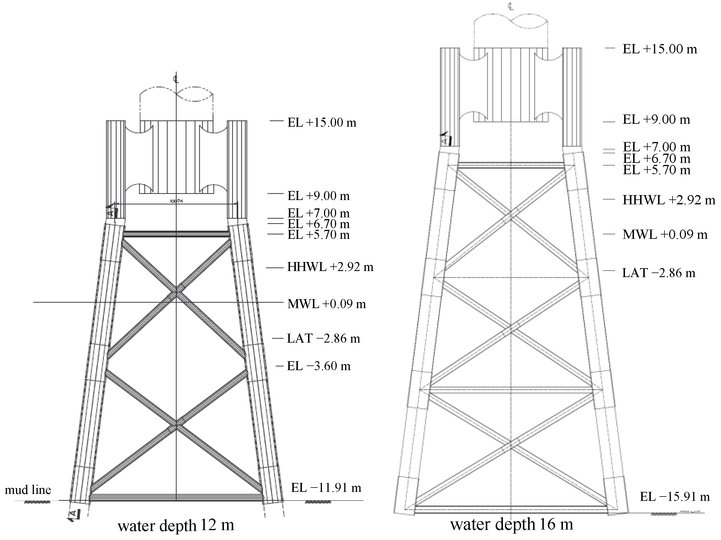
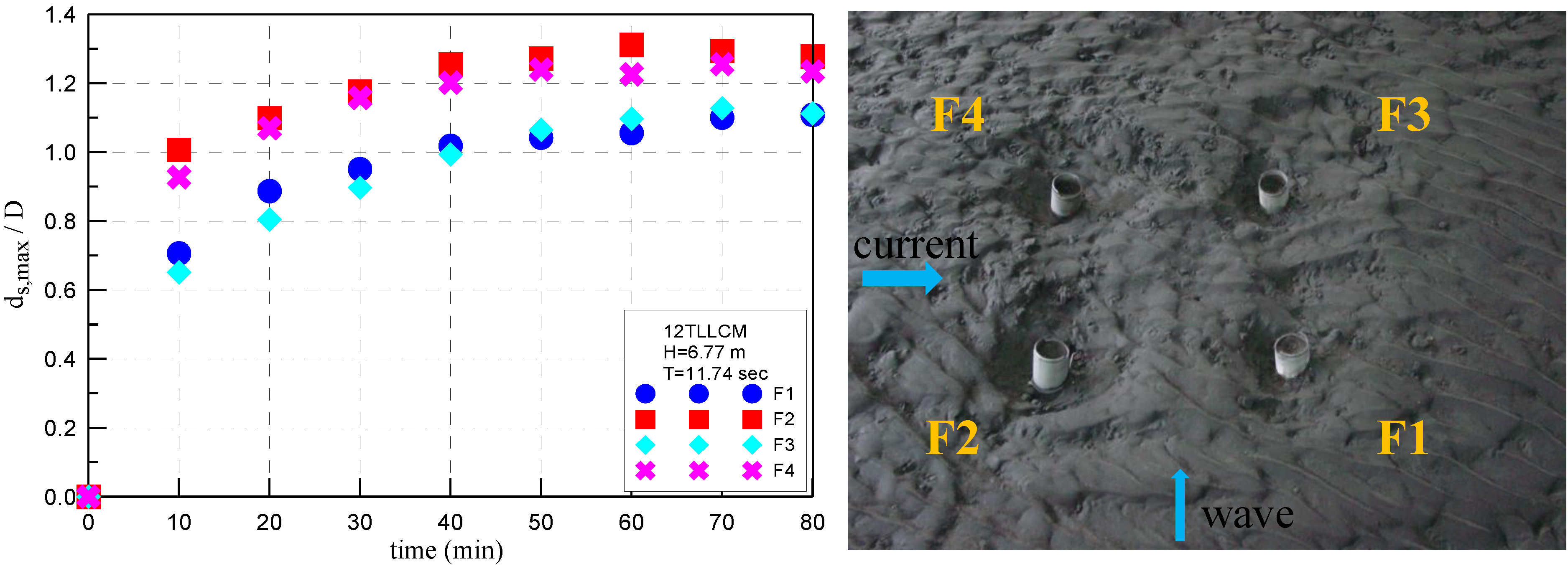
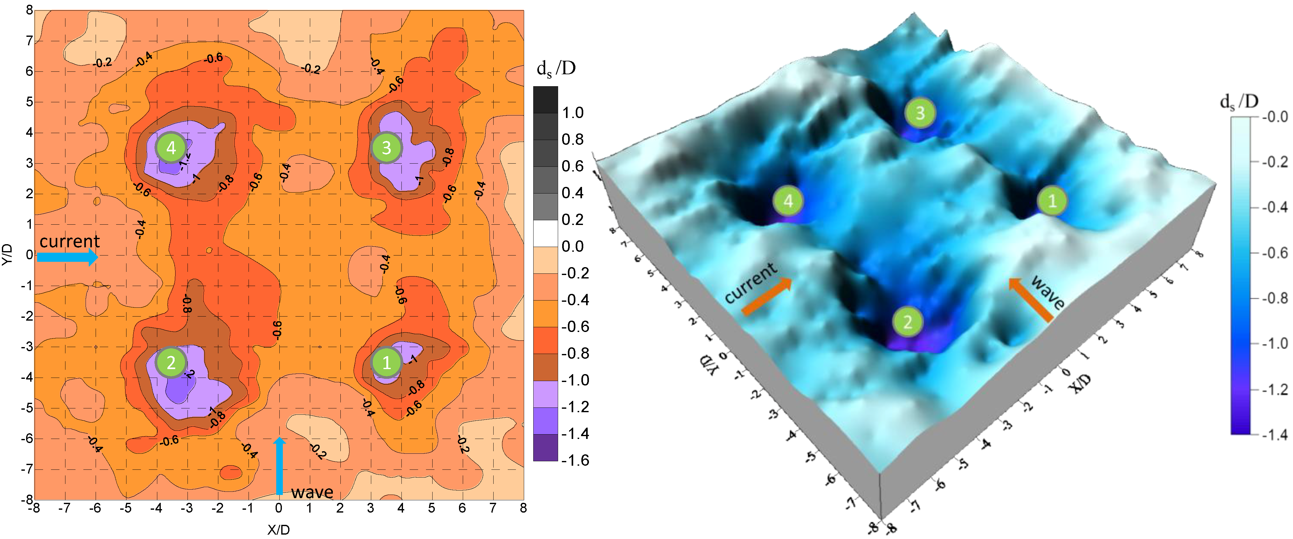
Figure 3.
The evolution of the scour depth around the four piles of the jacket-type foundation for the case, 12TLLCM, (12, 12-m water depth; T, 100-year return period typhoon wave; LL, lower low water level; C, current; M, mobile bed).
Figure 3.
The evolution of the scour depth around the four piles of the jacket-type foundation for the case, 12TLLCM, (12, 12-m water depth; T, 100-year return period typhoon wave; LL, lower low water level; C, current; M, mobile bed).
For the jacket-type foundation located at a water depth of 12 m, case 12TLLCM (12, 12-m water depth; T, 100-year return period typhoon wave; LL, lower low water level; C, current; M, mobile bed) is the most serious scour event exposed to the lowest water level, the action of the combined current and the 1:100 year return period typhoon wave. The maximum scour depths around the four piles of the jacket-type foundation are
ds1/D = 1.11,
ds2/D = 1.31,
ds3/D = 1.13 and
ds4/D = 1.26, respectively.
Figure 3 and
Figure 4 show the evolution of the maximum scouring depth and the potential impacted erosion area around four piles of the jacket-type foundation under the case, 12TLLCM. In this experiment, the angle between the incident wave and the current is 90°. The results show that more serious scouring will be induced at piles
ds2 and
ds4 on the up-current side of the foundation. From the observations, it is estimated that the length of the scour holes around the four piles of the foundation is approximately up to 4~6 times the pile diameter. However, when the foundation location changed to a 16-m water depth, the maximum scouring depth and the length of the scour hole are less than those obtained from the tests at a 12-m water depth (see
Table 2 and
Table 3). This is because, not only erosion, but also redeposition will occur within the experimental process under the location with a 16-m water depth.
Figure 4.
The 2 D and 3 D potential impact erosion area and scouring around the four piles with the jacket-type foundation under the case, 12TLLCM (80 min, i.e., after finishing the test).
Figure 4.
The 2 D and 3 D potential impact erosion area and scouring around the four piles with the jacket-type foundation under the case, 12TLLCM (80 min, i.e., after finishing the test).
From the experimental results, it is shown that the maximum scour depth usually occurs in the up-current or up-wave side of the jacket-type foundation. The scour differences resulting from the 12 m and the 16 m water depth come from pre-wave breaking before the jacket-type foundation at the 16 m water depth and the redeposition of sedimentation.
3.3. Hard Scour Protection for Jacket-Type Foundation
When the occurrence or uncertainties of a local scour hole around the foundation of a wind turbine are not desired, preventive or remedial countermeasures can be applied. Almost all of today’s knowledge about scouring behavior and the strategies for scour protection is based on physical experiments carried out in flumes in co-directional waves and current, with two-dimensional waves (for example, those of Sumer and Fredsøe [
11]). Typically, traditional hard scour protection will be realized by using layers of natural and crushed rock, which increase in size as one goes up from the seabed. The lowest layer of rock, which is small enough to restrain the soil, can be replaced by a geo-textil [
12].
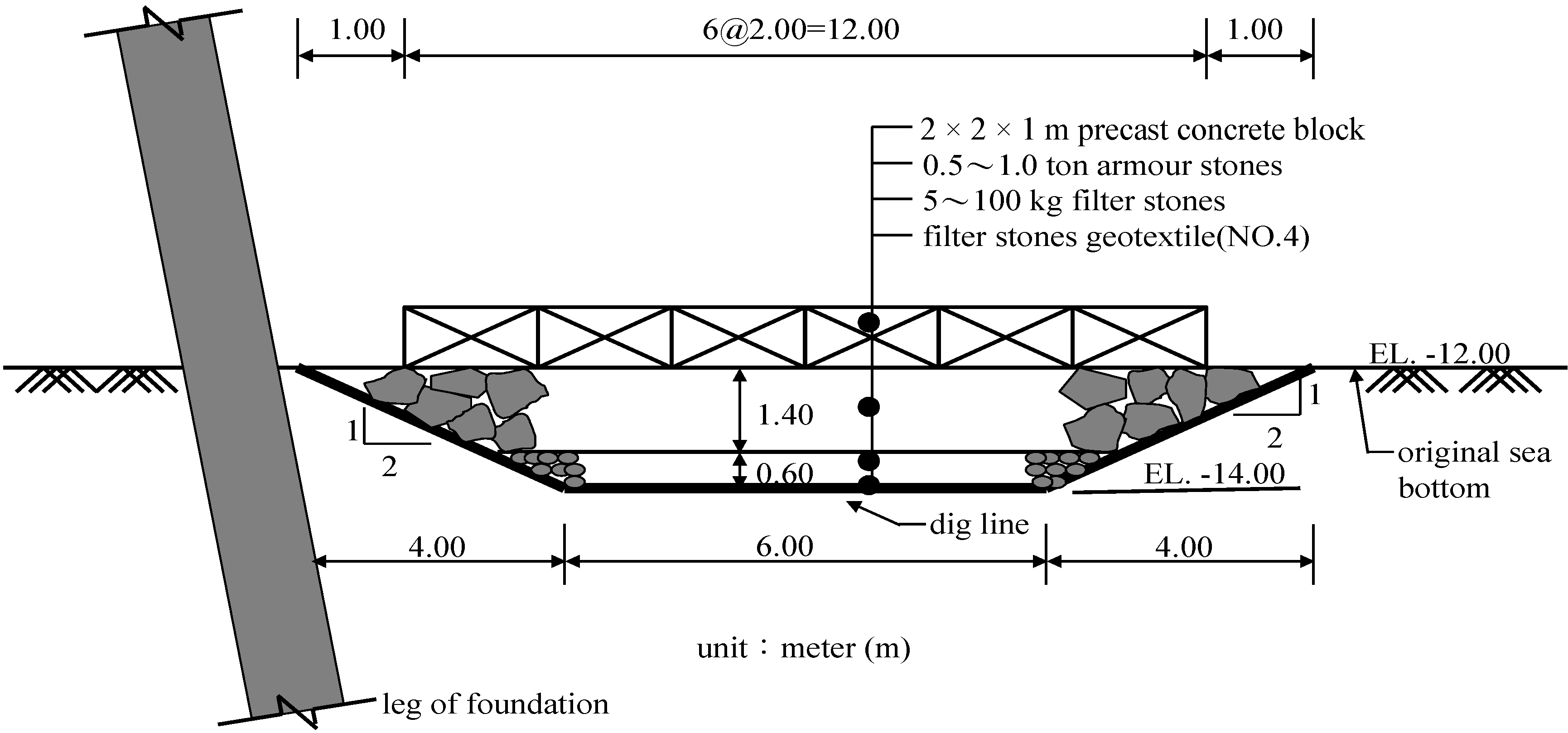
Therefore, based on the analysis from the former NSWB experimental results, one of the suitable traditional hard scour protections for the jacket-type foundation of an offshore wind turbine is firstly proposed and shown in
Figure 5. The proposed hard scour protection consists of:
- (1)
a precast concrete block: 2 m × 2 m × 1 m,
- (2)
armor stones: 0.5~1.0 ton, with a layer thickness of 1.4 m,
- (3)
filter stones: 5~100 kg, with a layer thickness of 0.6 m,
- (4)
geo-textile (No. 4).
Figure 5.
A sketch of the proposed hard scour protection for the jacket-type foundation.
Figure 5.
A sketch of the proposed hard scour protection for the jacket-type foundation.
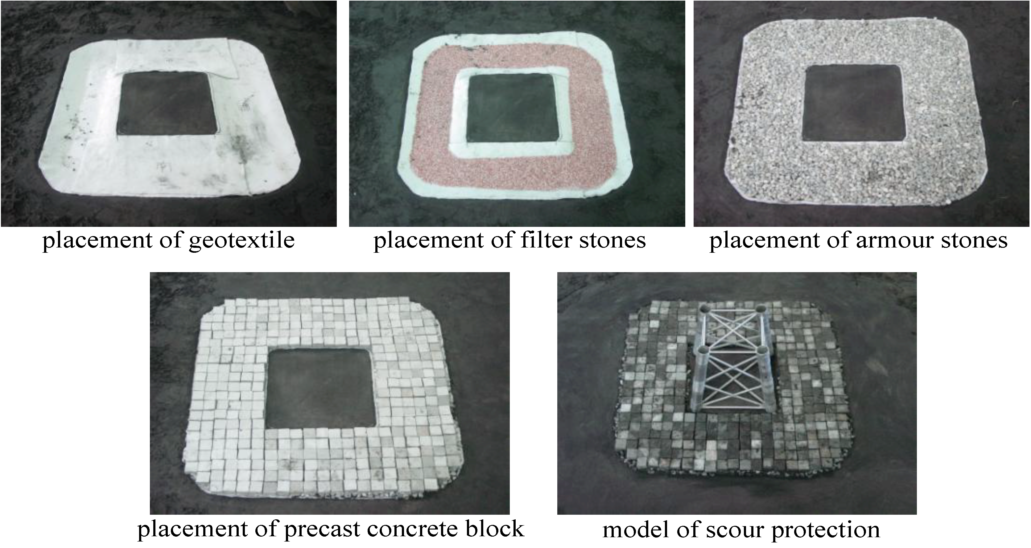
Figure 6.
The experimental setup of the hard scour protection for the jacket-type foundation.
Figure 6.
The experimental setup of the hard scour protection for the jacket-type foundation.
The edge of this proposed hard scour protection attains a slope of 1V:2H (V, vertical; H, horizontal). The experimental setup of the hard scour protection is shown in
Figure 6. If the rubble-mound structures and wave absorbers are modeled with the stone sizes geometrically reduced from the prototype scale, there will be relatively less wave transmission through the model structure. Frictional losses are greater in the model, as the wave travels through the structure, and this becomes particularly pronounced at the scales used for harbor models [
13]. This scale effect is countered by increasing the size of the model stones over that dictated by geometric scaling. The initial bed levels and scour protection block level are checked with bed profiles taken by a calibrated automatic bottom profiler. Pre- and post-test profiles are used to identify any settlement and stability in the precast concrete block and scouring in the surrounding seabed. From
Figure 7 and
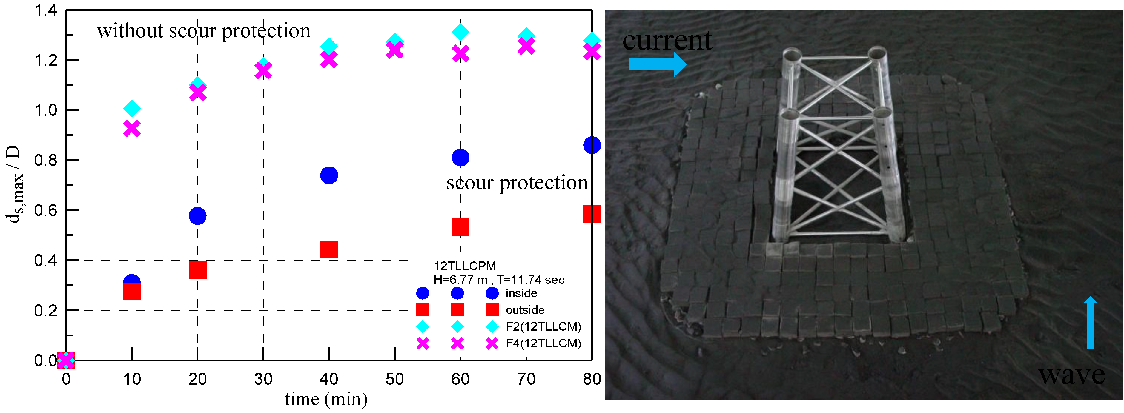
Figure 8, the results show that the protection block maintained the initial level and remained stable. Nevertheless, there is scouring of the bed outside the protection by up to 0.59 D and inside the foundation by up to 0.86 D locally. However, a four-layer hard scour protection is tested and found to be effective in preventing scouring around the jacket-type foundation of an offshore wind turbine.
Figure 7.
Comparison of maximum scour depth between the case, 12TLLCM (without scour protection), and the case, 12TLLCPM (with hard scour protection).
Figure 7.
Comparison of maximum scour depth between the case, 12TLLCM (without scour protection), and the case, 12TLLCPM (with hard scour protection).
Figure 8.
The potential impact erosion areas around the hard scour protection for the jacket-type foundation under the case, 12TLLCPM.
Figure 8.
The potential impact erosion areas around the hard scour protection for the jacket-type foundation under the case, 12TLLCPM.
3.4. Soft Scour Protection for Jacket-Type Foundation
Taiwan has plenty of offshore wind power resources in the western coastal water areas, but they have not yet been utilized, unlike the resources of land wind, which mostly has been applied and arranged. The government expected the renewable proportion of energy to reach the goal of 15.1% in 2025, including 5.3% from offshore wind power. This reveals that offshore wind power is the most important and urgent renewable energy, which increases the most and is larger than expectations. However, this amount of electricity from offshore wind energy requires a sizable coastal water area, which is currently shared by various users, including fishermen, shipping lines, recreation, tourism, and others. Thus, public acceptance of offshore wind farms is very important for the success of offshore wind energy development in the western Taiwan coastal water area, and it is necessary for developers to explore the concerns of these different users. Besides, various stakeholders are involved in the marine environment and have different opinions about offshore wind energy. Fishermen are an important stakeholder group, because the livelihoods of commercial fishermen could be significantly affected by the installation of offshore wind turbines. Taking Germany as an example, the coastline of Germany is very short, and the overlapping usage of the offshore water area is very frequent. In order to reduce the conflicts between users, multiple usage policies, which combine offshore wind farms and aquaculture, could be adopted by using the structure of offshore wind farms to fasten aquaculture to prevent cultivated organisms from sinking because of the sea current [
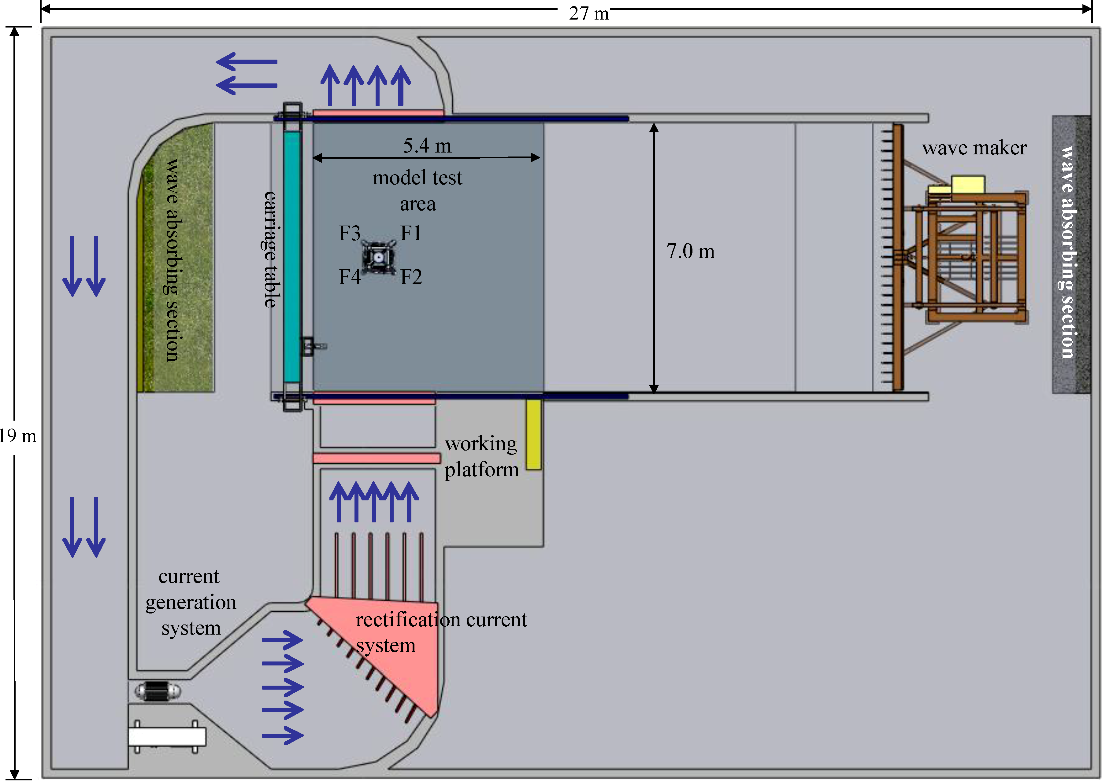
14]. Thus, this study also considers the concept of the usage of integrative coastal space to combine offshore wind turbines and coastal cage nets, to analyze different distances and optimum cage net depths and, furthermore, to discuss these factors of coastal cage nets, which could slow down the erosion around wind turbine foundation. The cage net diameter is 18 m, which is the same as the outer width (W) of the jacket-type foundation. The tested cage net depths are 4 m, 8 m and 12 m, which are 1/4, 2/4 and 3/4 of the water depth (h) of 16 m in the field site. Meanwhile, the local stakeholders’ opinion about combining offshore wind energy with coastal cage net aquaculture should be deeply understood. Two series of physical model tests with the same 1:36 scale fixed-bed and mobile bed experiments were performed in this soft scour protection study. The aim of the first test series is to investigate the optimum location and depth of coastal cage nets to reduce the hydrodynamic conditions (100 return period typhoon wave or current) around the jacket-type foundation by the fixed-bed experiments. Another test is aimed at differentiating the greatest magnitude of local scour and potential scour areas in the sand bed around the jacket-type foundation with the optimum location and depth of the coastal cage nets by mobile bed experiments. Meanwhile the Delphi method is used to analyze the related stakeholders’ opinions about the integration of offshore wind energy and coastal cage net aquaculture in the intermediate water depth and their experience and knowledge to reconcile the asymmetry between government and communities.
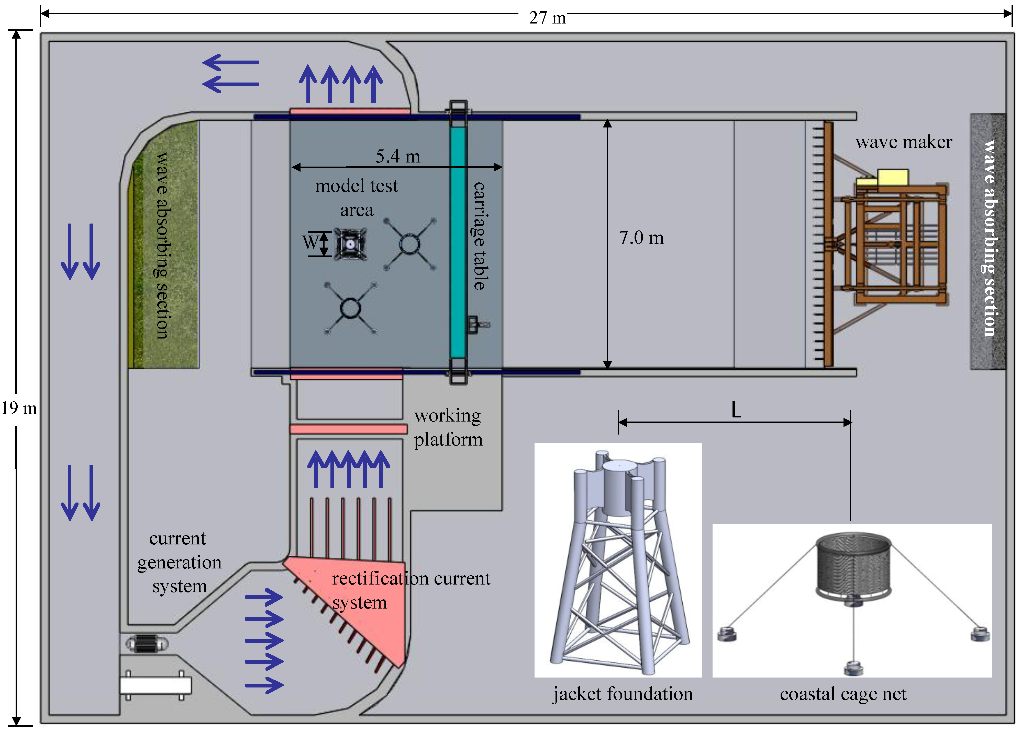
The layout of the 27 m × 19 m wave-current basin for the fixed-bed experimental setup is shown in
Figure 9. The wave flume passes from right to left, and the current-generation flume circulates from the downside to the upside. The test area with the models of the jacket-type foundation and coastal cage nets within the water depth of 16 m in the field site is at the junction of these two flumes. The physical modeling is carried out in this wave-current basin at the Tainan Hydraulics Laboratory (THL) with a scale of 1:36. Froude’s law is obeyed in the fixed-bed experiment. The equipment and measurement system used in this experiment include an irregular wave maker, a current-generation system, electrical capacitance wave gauges and acoustic doppler velocimeters (ADV). From the fixed-bed experimental results, it is shown that the up-current optimum location of coastal cage nets in front of the jacket-type foundation can have a good effect at reducing the current speed under the conditions that the distance between the cage net and foundation is two-times the foundation width (W). However, with the up-wave location of the coastal cage net in front of the jacket-type foundation, the wave attenuation effect near the wind turbine foundation is not so obvious. From the fixed-bed experimental results, the optimum cage net water depth is up to 0.75 (3/4 h, 12-m cage net depth
in-situ) for reducing the current speed.
Figure 9.
A sketch of the experimental setup for the jacket-type foundation and coastal cage net.
Figure 9.
A sketch of the experimental setup for the jacket-type foundation and coastal cage net.
After the fixed-bed experimental tests, the mobile experimental study on the soft scour protection for the jacket-type foundation for offshore wind turbines is further conducted. The sediment used in this movable-bed experiment is light density coal (the specific gravity of coal, γ
c = 2.02) of a median grain size d
50 = 0.15 mm, and the model sand bed is 0.35 m deep, 7.0 m long and 5.4 m wide. The equipment and measurement system used in this mobile bed experiment include the same system used in the fixed-bed experiment together with the ultrasonic bottom profiler moved by the carriage table. From
Table 4 and
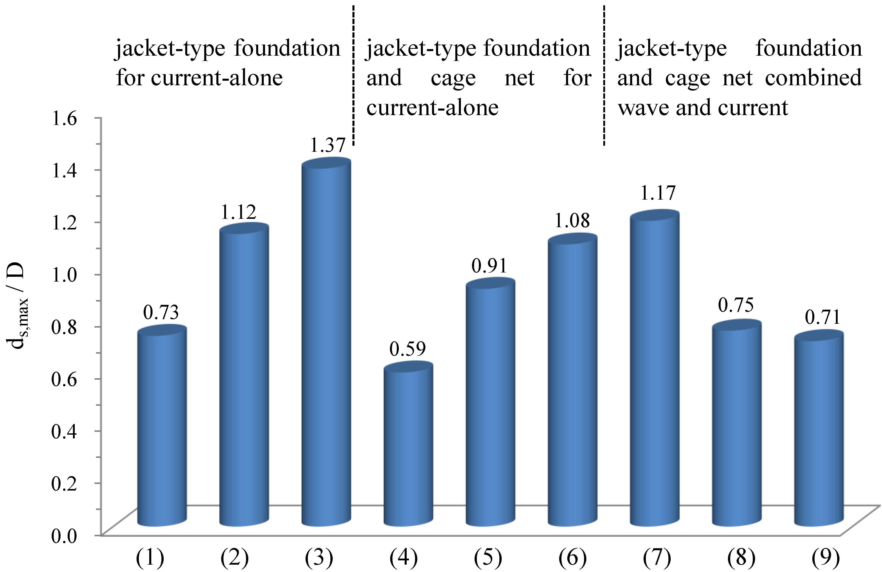
Figure 10, the evolution of the maximum scour depth with the different test conditions for the jacket-type foundation is shown. For the current-alone case (a current of 1.5 m/s), the scour hole can reach a maximum depth (
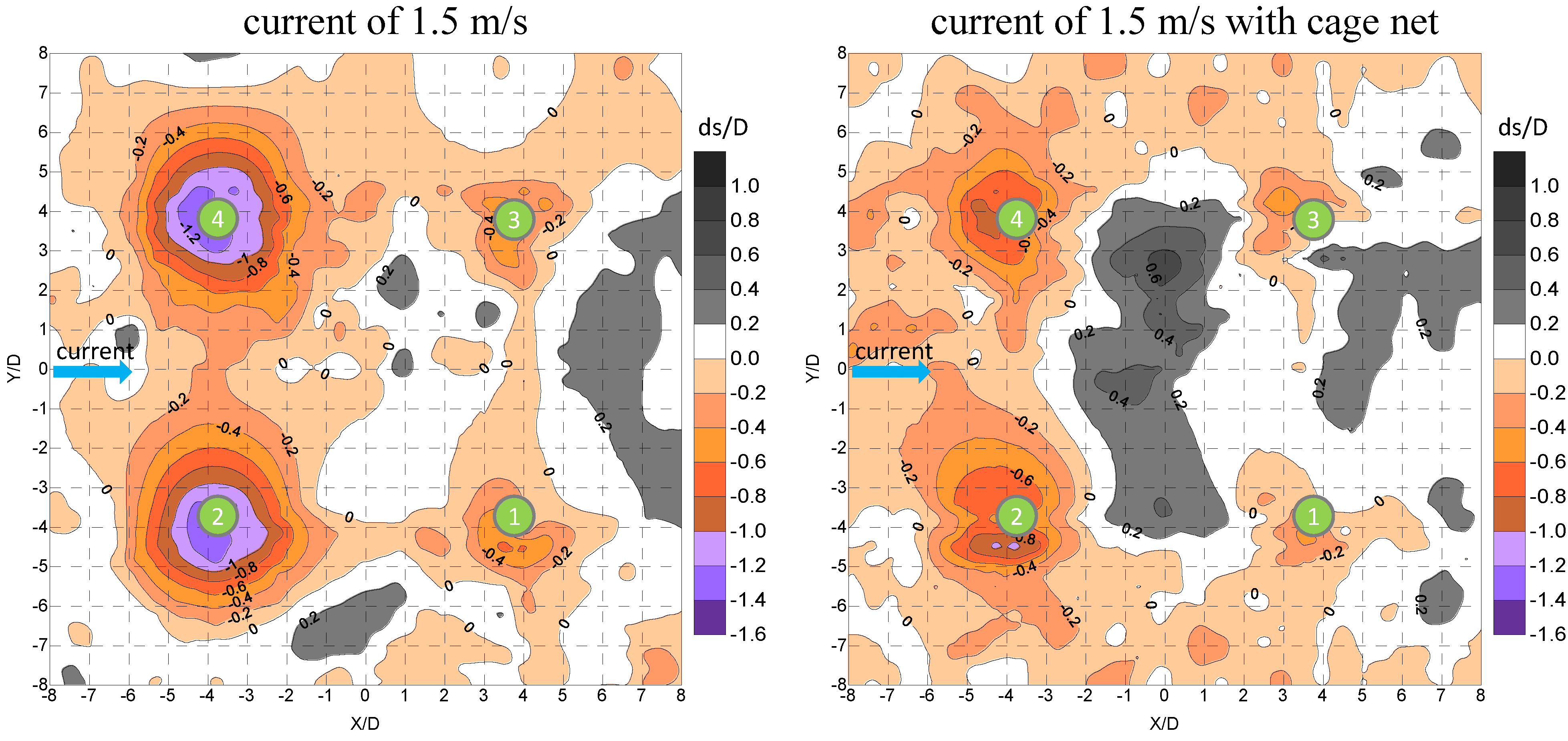
ds,max) of 1.37-times the pile diameter (D) of the jacket-type foundation without the coastal cage net. However, if we locate the coastal cage net in front of the wind turbine on the up-current side optimum position (2W), the maximum scour depth can be reduced to 1.08 D, and the redeposition phenomenon occurred inside the jacket-type foundation; see
Figure 11. Regarding the combined typhoon wave and current loading tests, the maximum scour depth can be from 1.17 D (without the cage net) to 0.75 D (one cage net at the up-current side) or 0.71 D (one cage net at the up-current side, another one at the up-wave side). Therefore, the cage net can reduce the current rate and scouring around the jacket-type foundation.
Table 4.
The maximum scour depth around the four piles of the jacket-type foundation and the coastal cage net (a water depth of 16 m) under different hydrodynamic conditions (D = 2.08 m).
Table 4.
The maximum scour depth around the four piles of the jacket-type foundation and the coastal cage net (a water depth of 16 m) under different hydrodynamic conditions (D = 2.08 m).
| Test Case | ds1/D | ds2/D | ds3/D | ds4/D | Test Case | ds1/D | ds2/D | ds3/D | ds4/D |
|---|
| current of 0.5 m/s | 0.35 | 0.66 | 0.40 | 0.73 | 0.5 m/s cage net | 0.26 | 0.59 | 0.31 | 0.53 |
| current of 1.0 m/s | 0.61 | 1.12 | 0.76 | 1.11 | 1.0 m/s cage net | 0.52 | 0.91 | 0.53 | 0.87 |
| current of 1.5 m/s | 0.70 | 1.24 | 0.62 | 1.37 | 1.5 m/s cage net | 0.46 | 1.08 | 0.46 | 0.87 |
| 16TLLCM1 cage net * | 0.75 | 0.65 | 0.71 | 0.64 | 16TLLCM2 cage net ** | 0.70 | 0.48 | 0.45 | 0.71 |
Figure 10.
The maximum scour depths under the different test conditions for the jacket-type foundation and coastal cage net.
Figure 10.
The maximum scour depths under the different test conditions for the jacket-type foundation and coastal cage net.
Note: (1) current of 0.5 m/s; (2) current of 1.0 m/s; (3) current of 1.5 m/s; (4) current of 0.5 m/s + cage net; (5) current of 1.0 m/s + cage net; (6) current of 1.5 m/s + cage net; (7) typhoon wave + current of 1.0 m/s; (8) typhoon wave + current of 1.0 m/s + cage net (up-current side); (9) typhoon wave + current of 1.0 m/s + 2 cage net (up-current side and up-wave side).
Figure 11.
The potential impact erosion area and scouring around four piles of the jacket-type foundation and cage net under the current-alone case (a current of 1.5 m/s).
Figure 11.
The potential impact erosion area and scouring around four piles of the jacket-type foundation and cage net under the current-alone case (a current of 1.5 m/s).
Besides the above experimental studies, this study also has made a preliminary analysis for stakeholders’ opinions on offshore wind energy and coastal aquaculture to understand the real demand for adjusting the dilemma of the marine space utilization in the western Taiwan coast. The stakeholders’ opinions are collected from four groups, including government, offshore wind farm developers, environmental groups and residents. From this preliminary feasible analysis for stakeholders’ opinions, the results show that the four groups can accept the concept of an integration of offshore wind farms and cage net aquaculture for the western Taiwan coastal water utilization. However, a detailed layout for the integration of offshore wind farms and coastal aquaculture should be investigated in the near future.


