Spin-ARPES EUV Beamline for Ultrafast Materials Research and Development

 , , , ,
Abstract
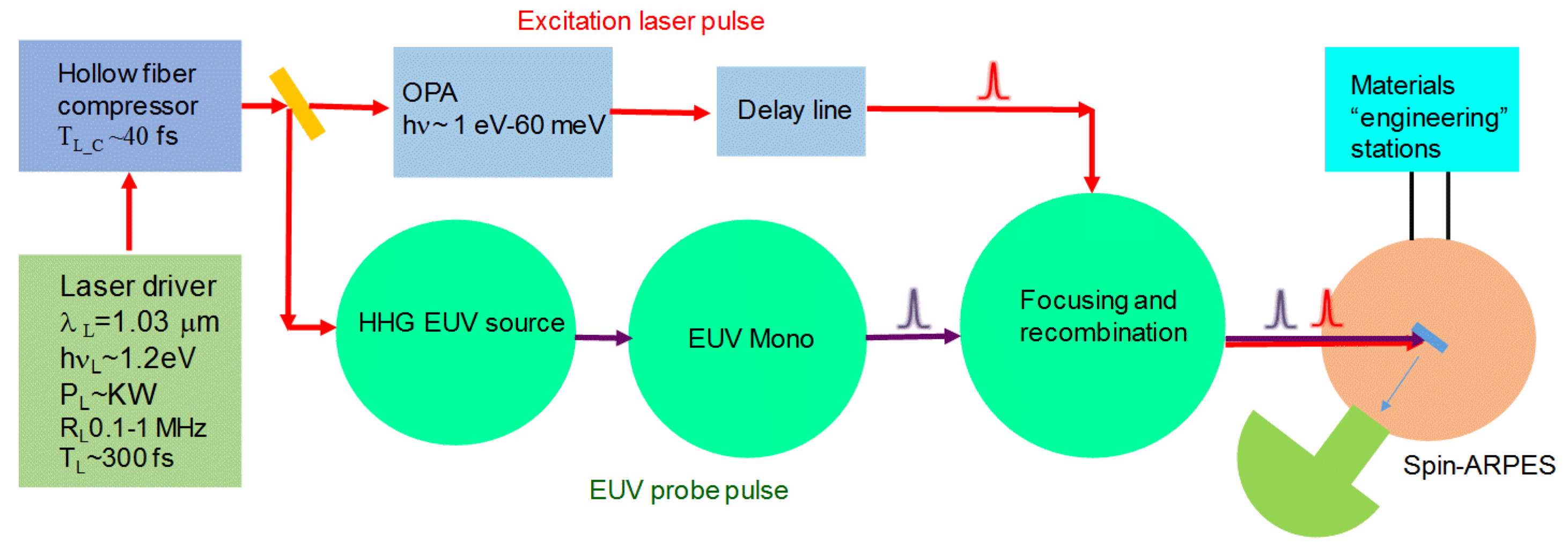
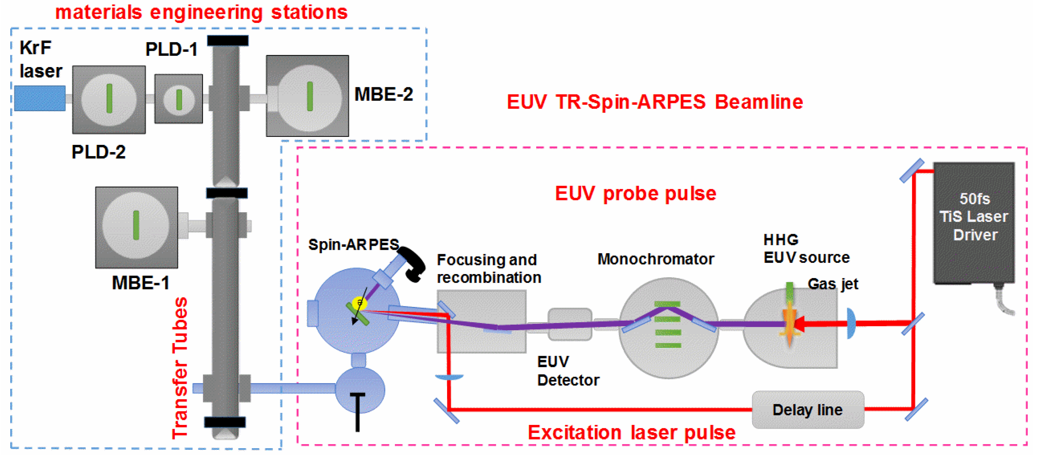
:1. Introduction
2. Femtosecond Laser-Driver
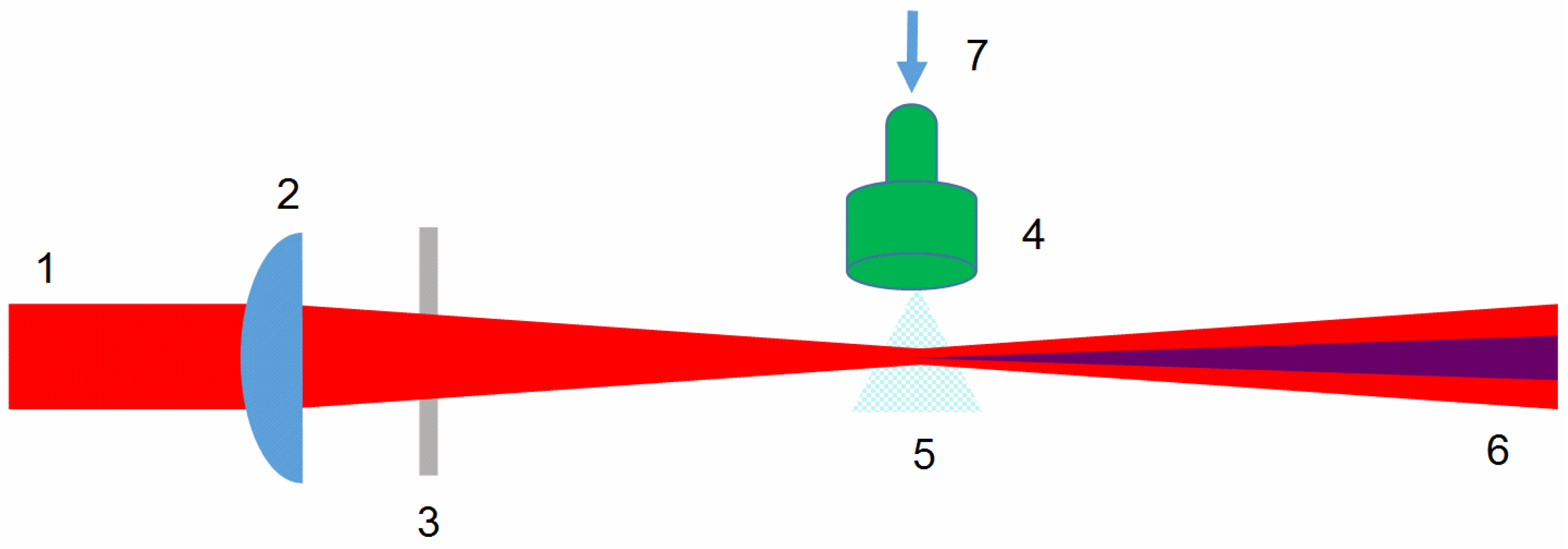
3. HHG EUV Source
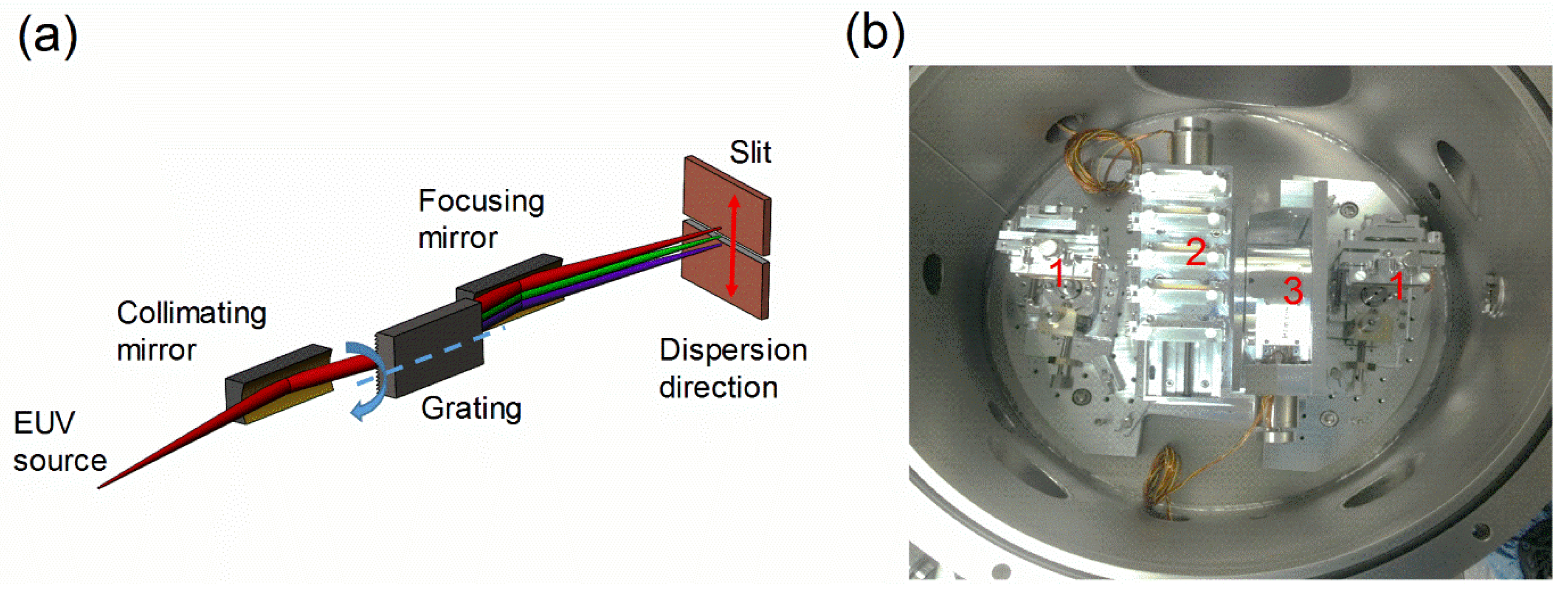
4. EUV Pulse-Preserving Monochromator
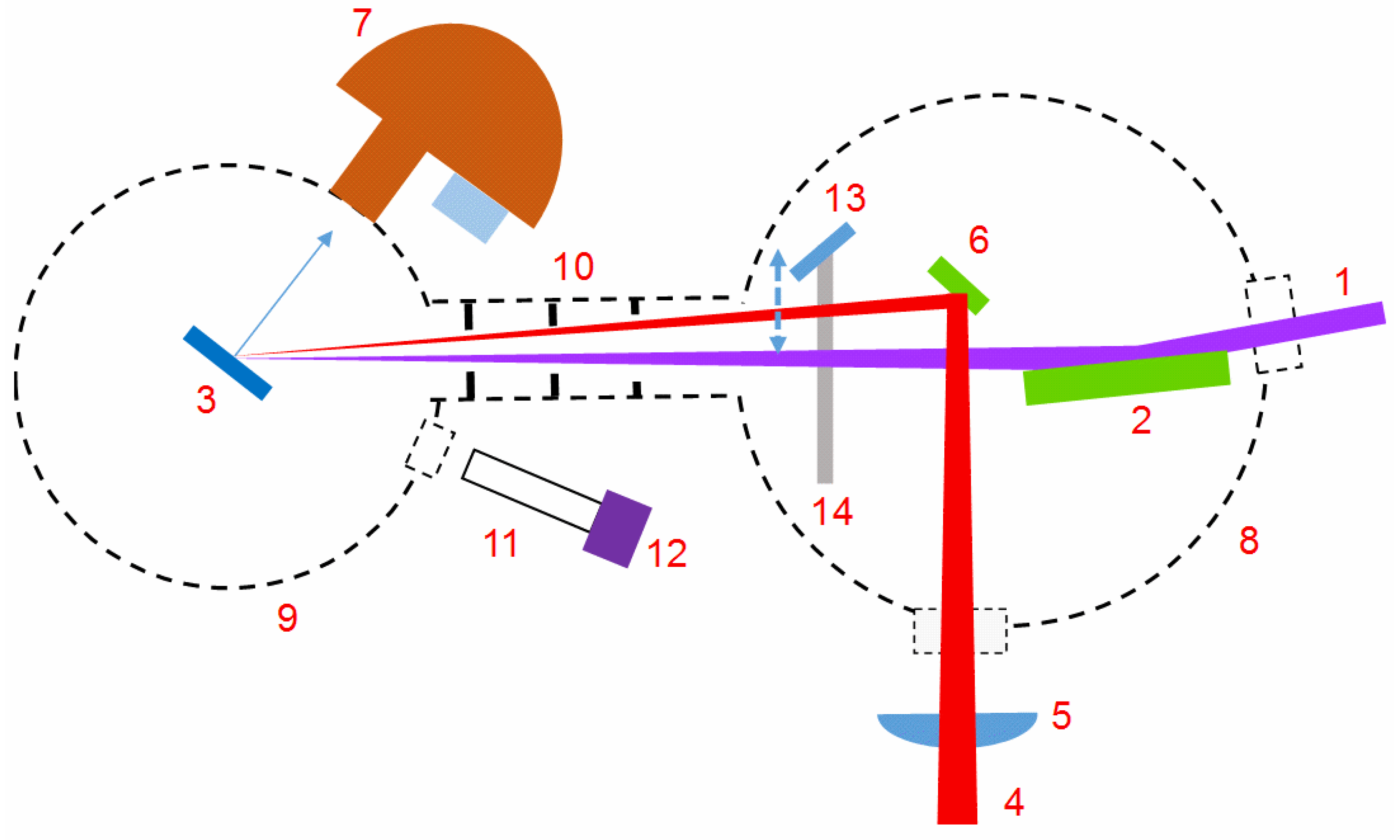
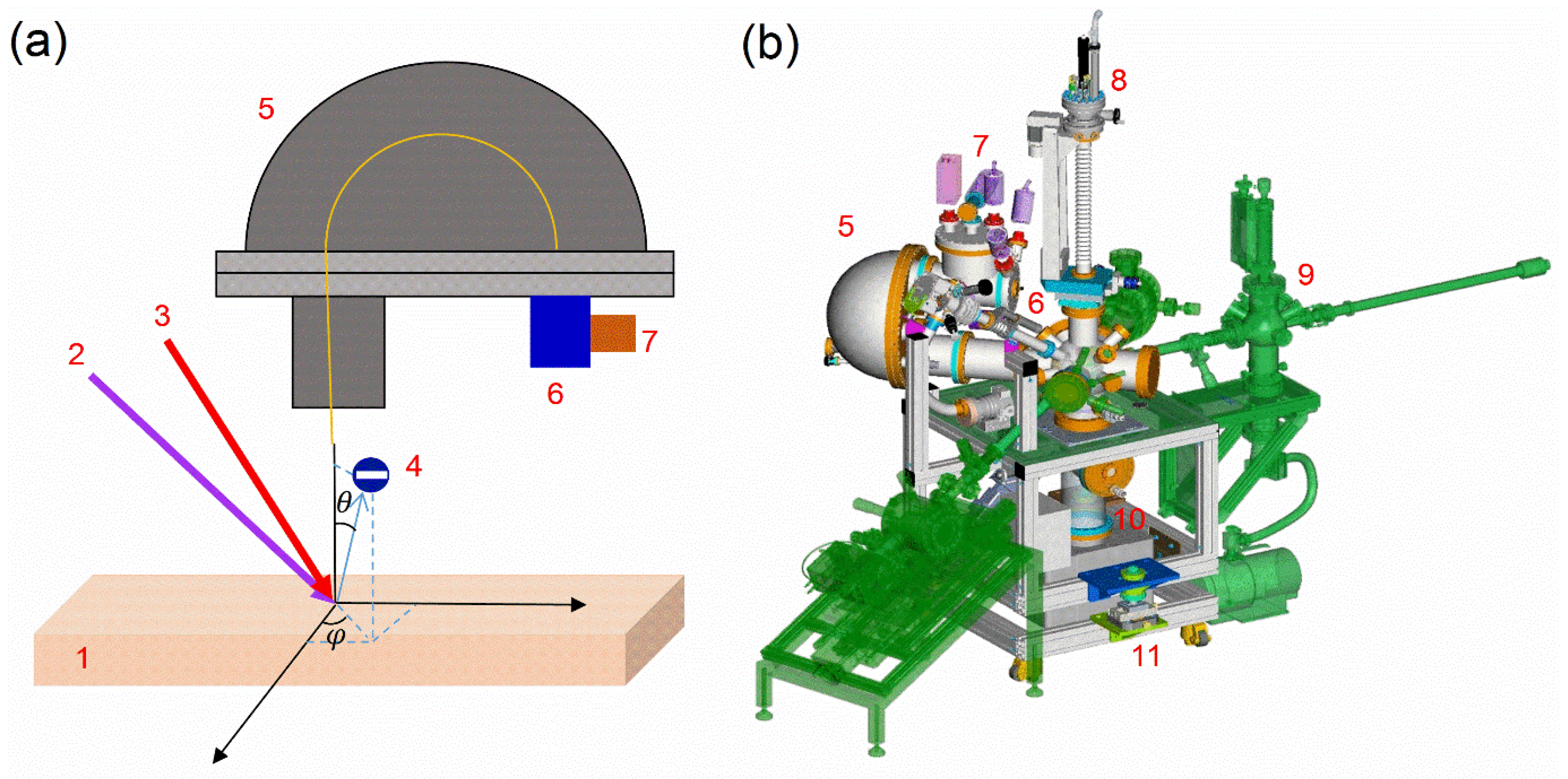
5. Focusing and Recombination of the EUV and Excitation Pulses
6. Spin-ARPES Electron Spectrometers
7. Ultrafast Materials Engineering Stations
7.1. Molecular Beam Epitaxy Stations
7.2. Pulsed Laser Deposition Stations
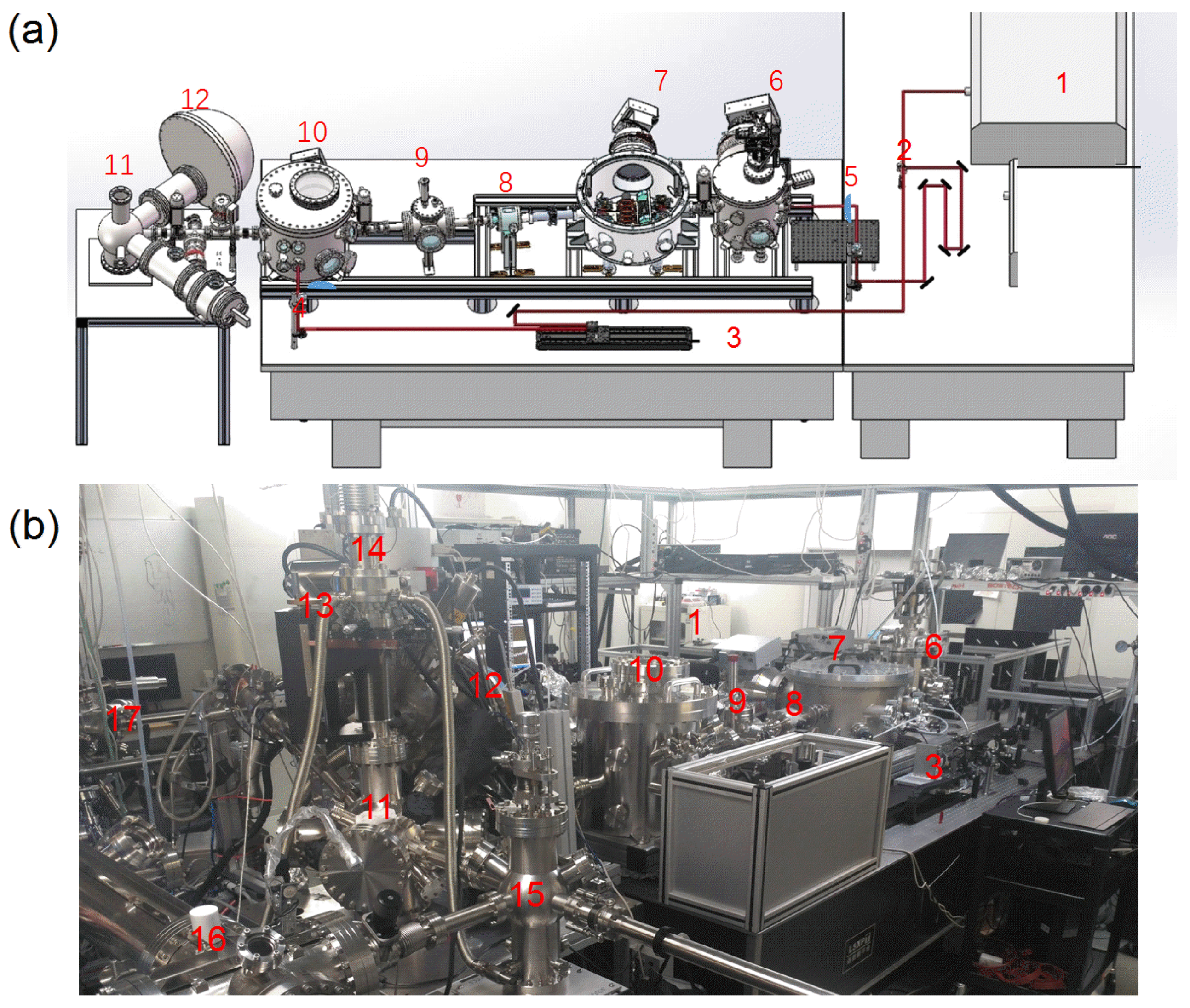
8. EUV Beamline Experimental Characterization
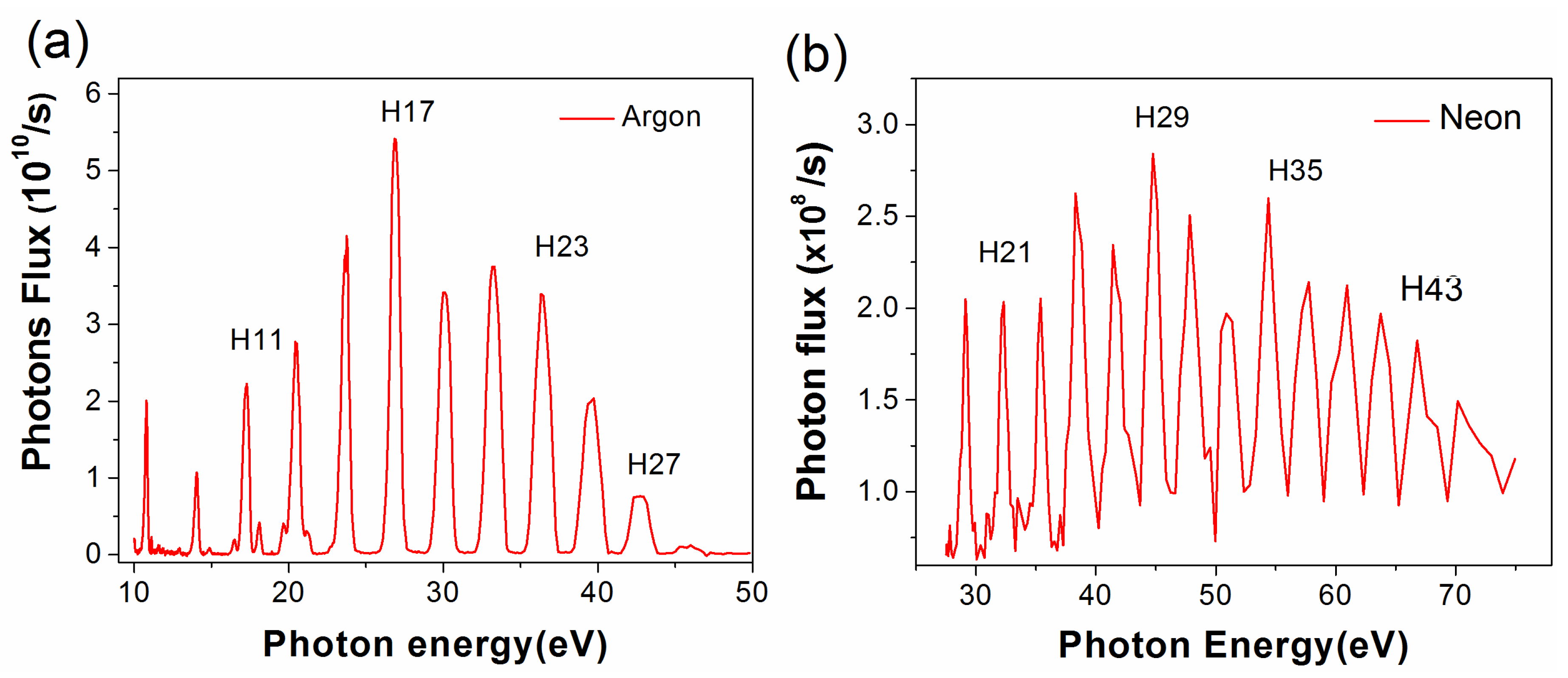
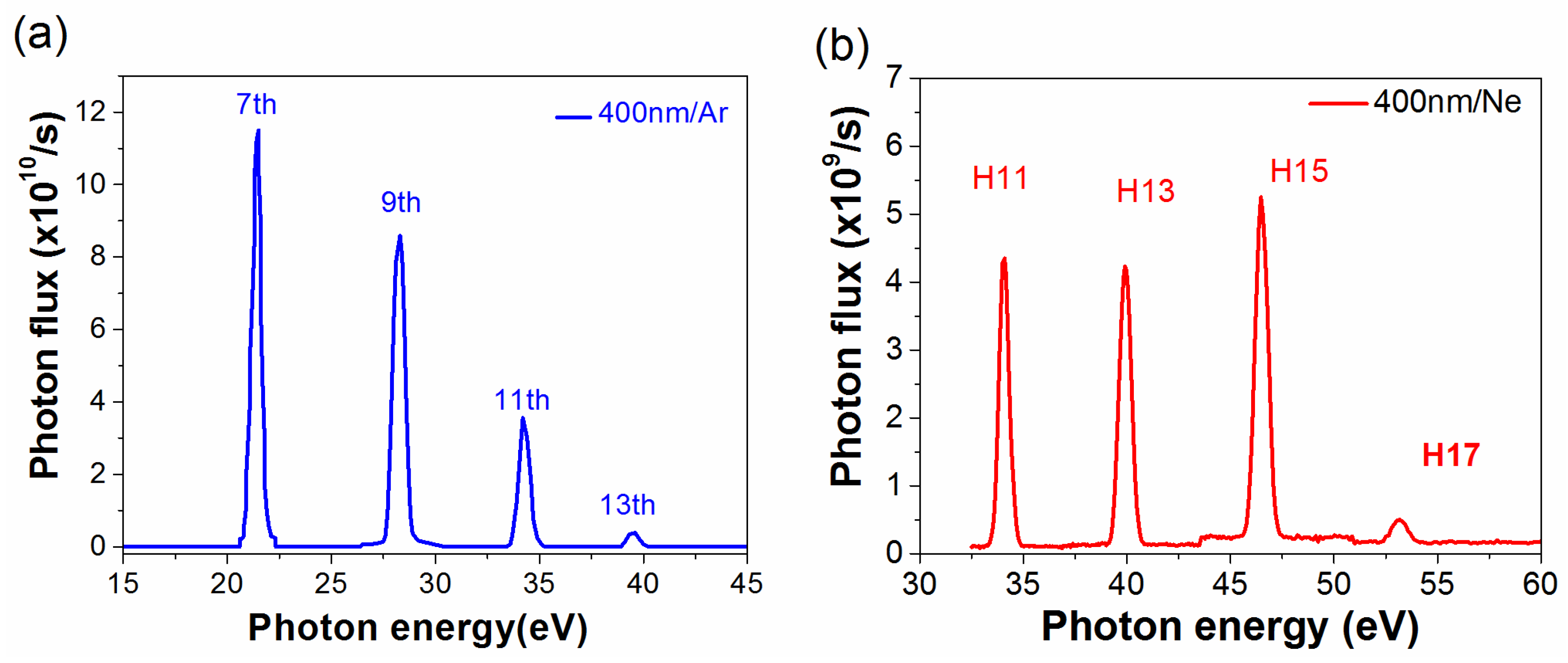
8.1. HHG EUV Spectra
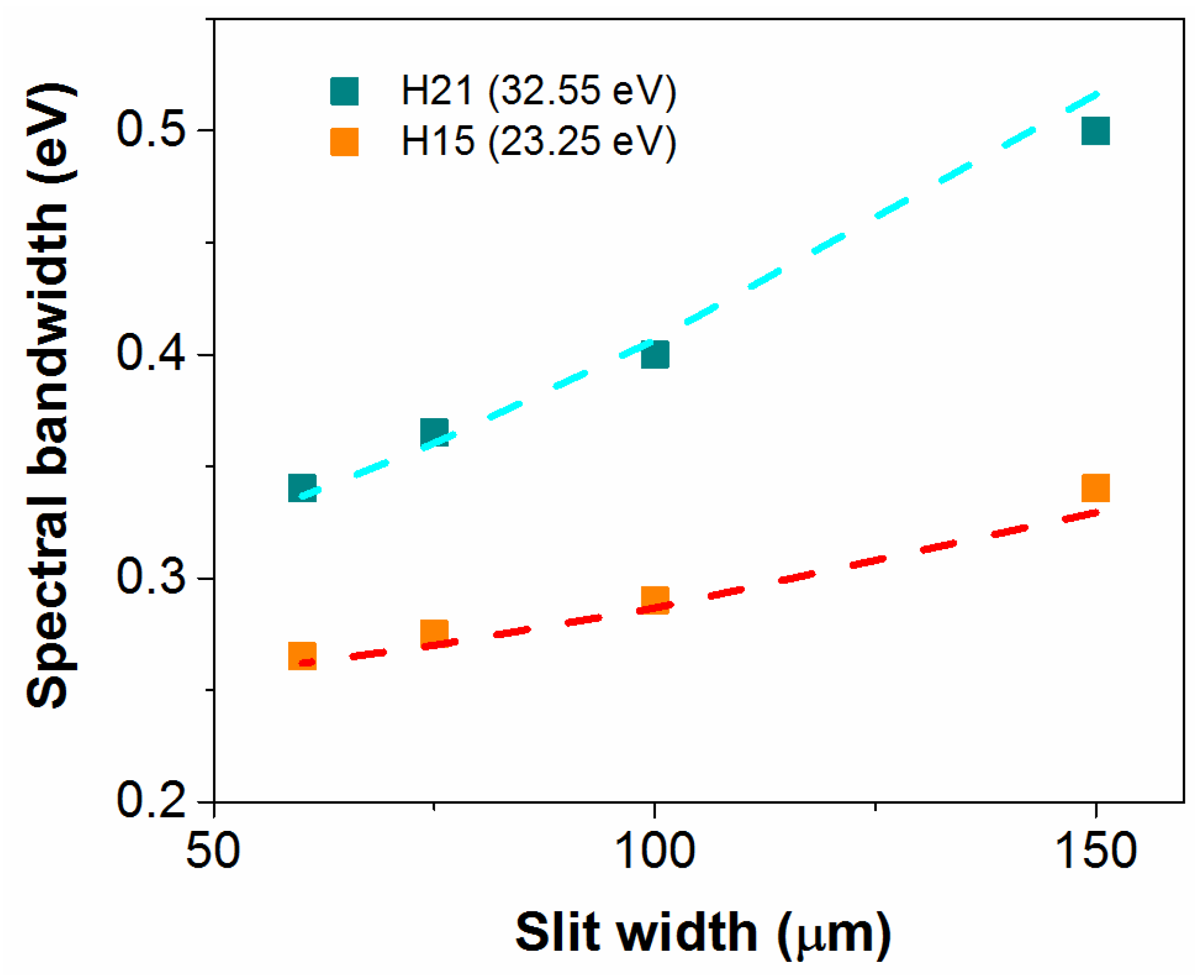
8.2. EUV Spectral Bandwidth
8.3. Pulse Front-Tilt Induced by Gratings: Effect on EUV Pulse Duration
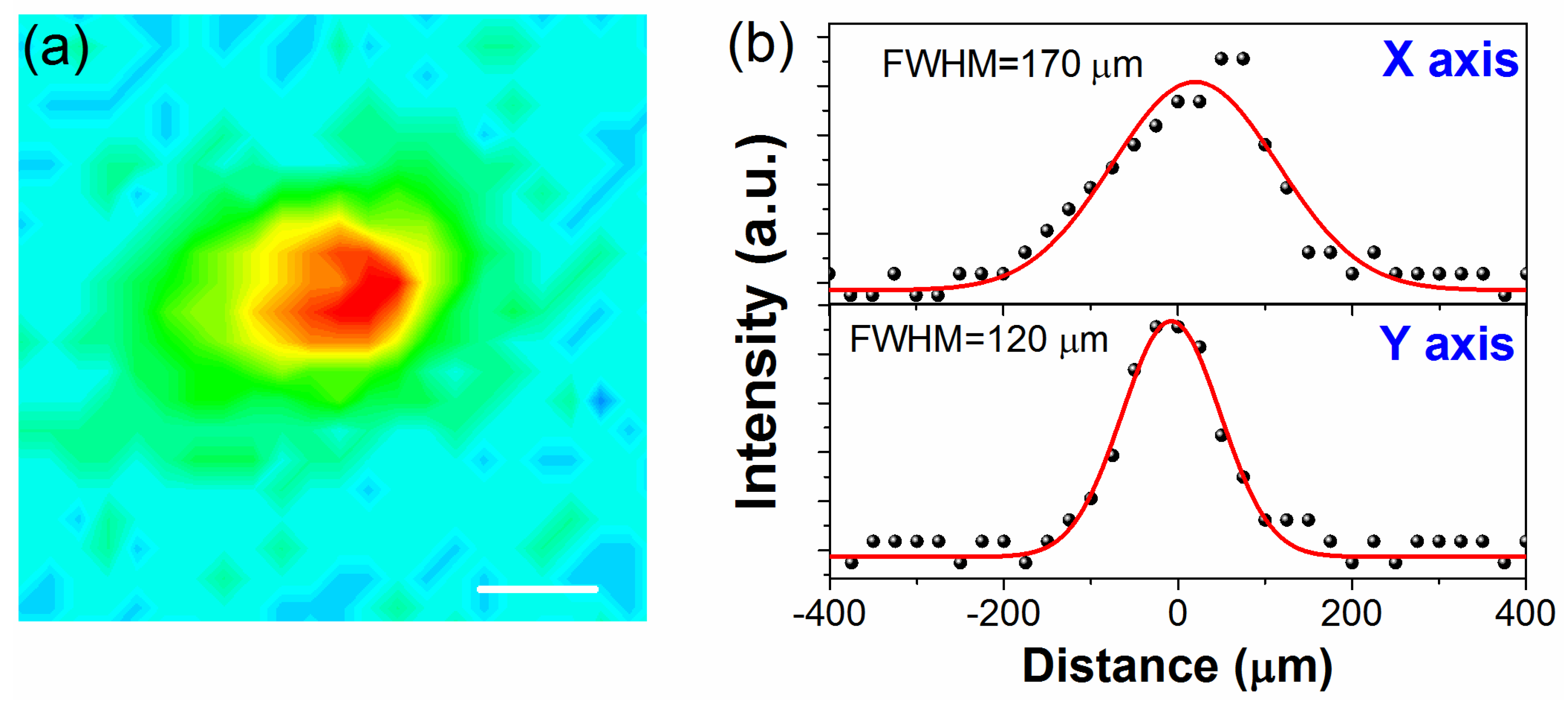
8.4. EUV Focused Spot Size on the Sample Material
8.5. Space Charge Effect at the Sample Material
9. TR-ARPES Spectra Measurements
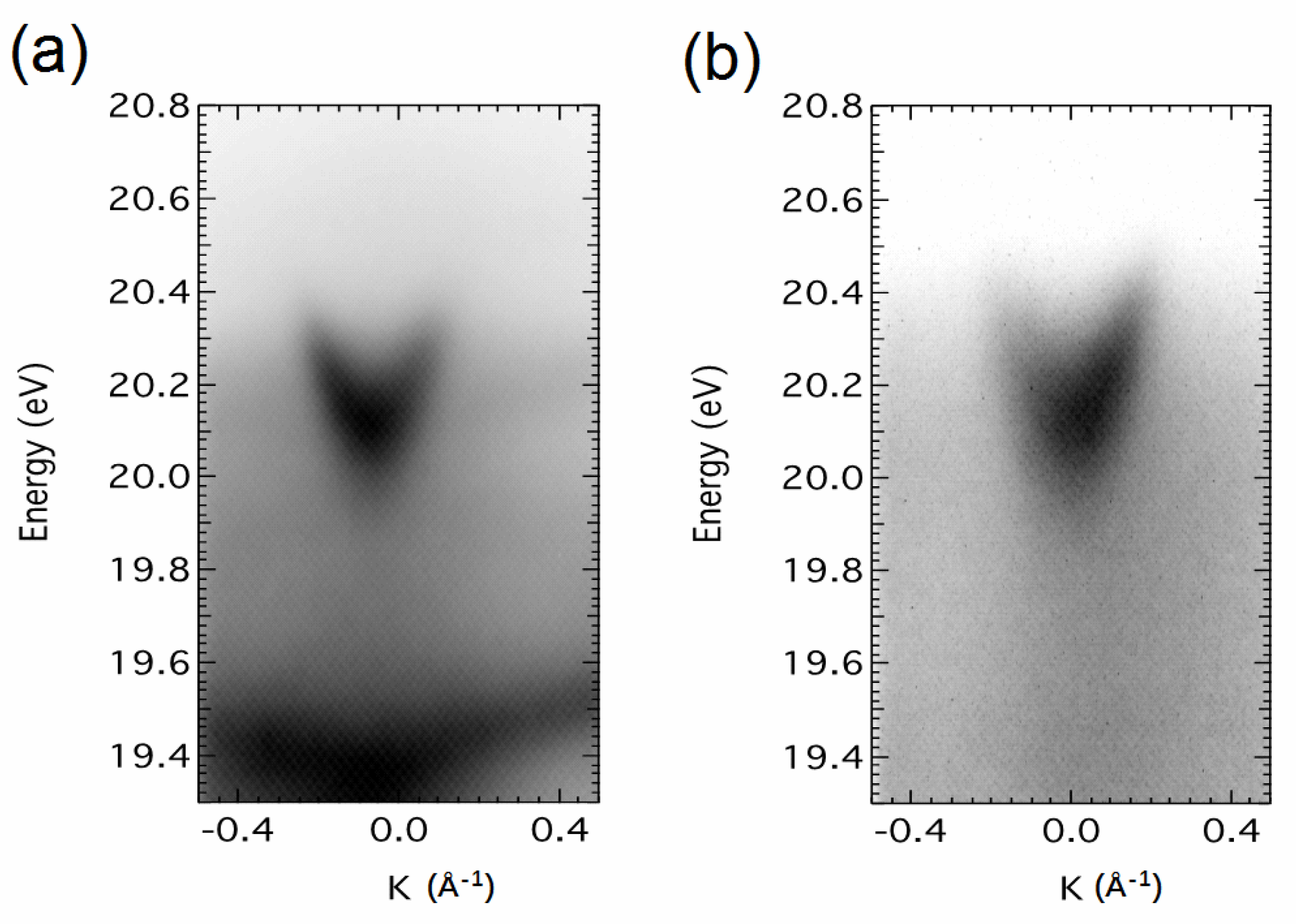
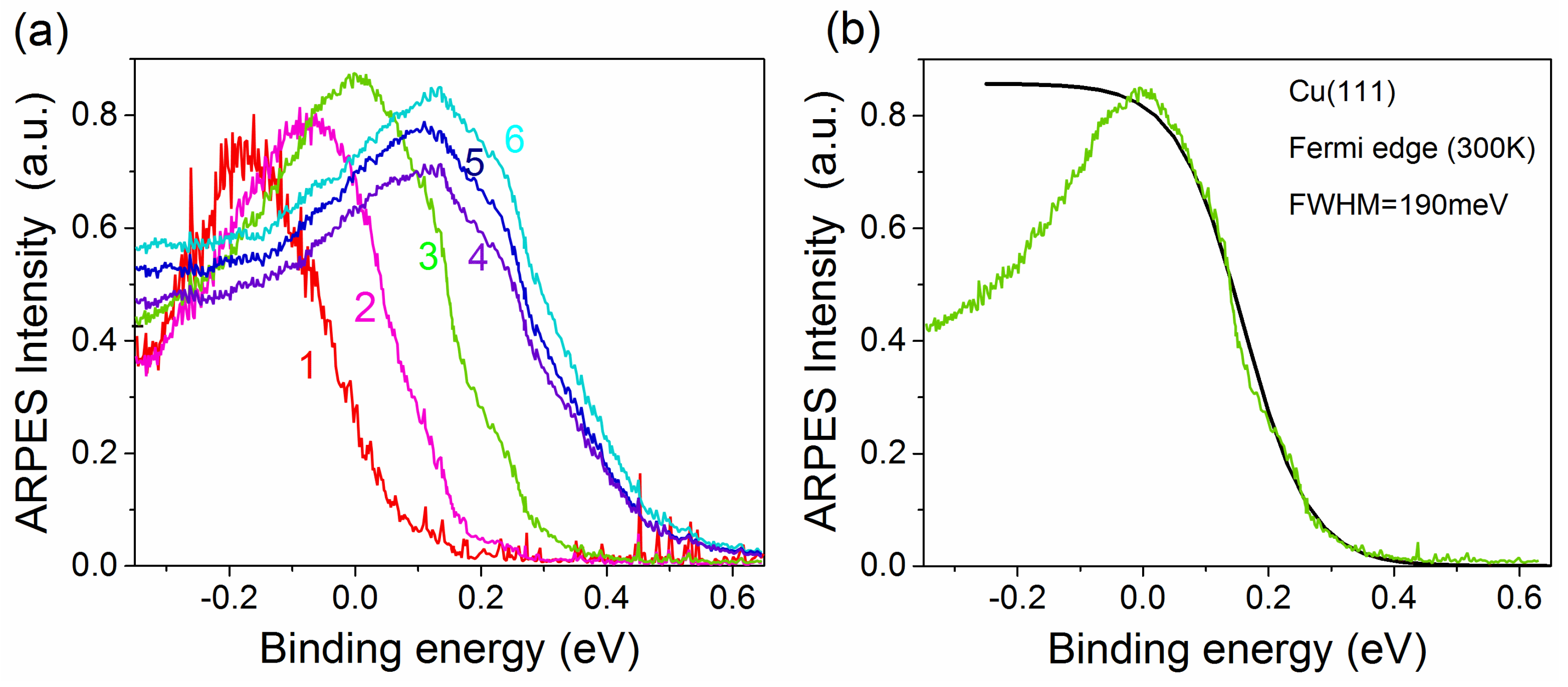
9.1. Static ARPES Spectra of Cu (111)
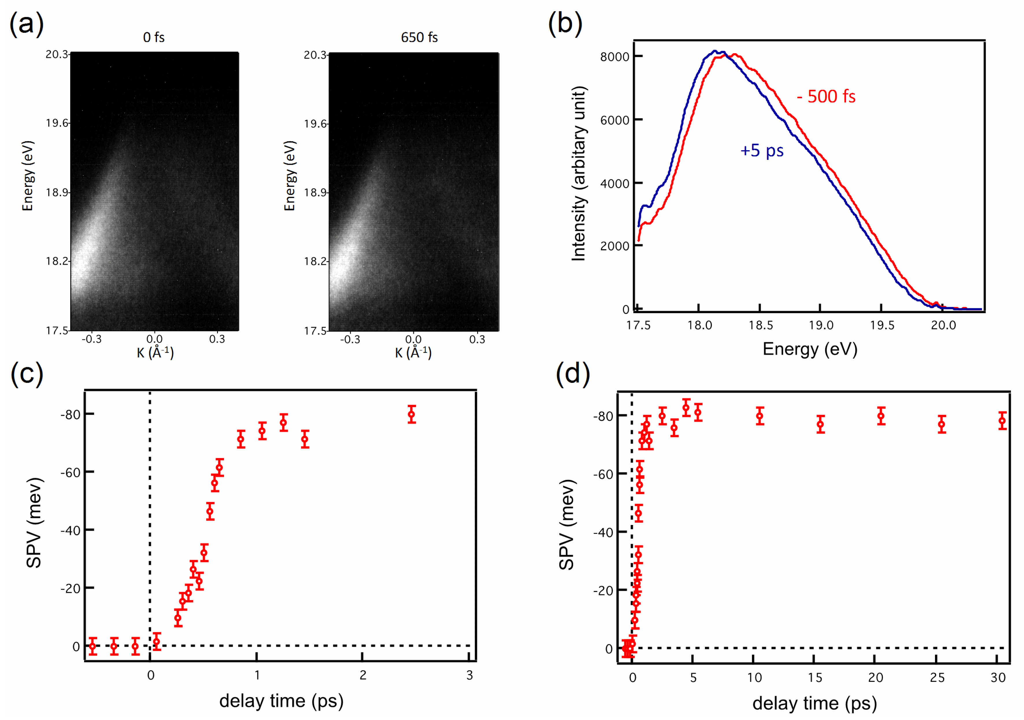
9.2. TR ARPES Spectra of p-type GaAs (100)
10. EUV Beamline Scaling to a 1 MHz Repetition Rate
11. Conclusions
Author Contributions
Funding
Acknowledgments
Conflicts of Interest
References
- Damascelli, A.; Hussain, Z.; Shen, Z.X. Angle-resolved photoemission studies of the cuprate superconductors. Rev. Mod. Phys. 2003, 75, 473–541. [Google Scholar] [CrossRef] [Green Version]
- Koralek, J.D.; Douglas, J.F.; Plumb, N.C.; Griffith, J.D.; Cundiff, S.T.; Kapteyn, H.C.; Murnane, M.M.; Dessau, D.S. Experimental setup for low-energy laser-based angle resolved photoemission spectroscopy. Rev. Sci. Instrum. 2007, 78, 053905. [Google Scholar] [CrossRef] [PubMed] [Green Version]
- Koralek, J.D.; Douglas, J.F.; Plumb, N.C.; Sun, Z.; Fedorov, A.V.; Murnane, M.M.; Kapteyn, H.C.; Cundiff, S.T.; Aiura, Y.; Oka, K.; et al. Laser based angle-resolved photoemission, the sudden approximation, and quasiparticle-like spectral peaks in Bi2Sr2CaCu2O(8+delta). Phys. Rev. Lett. 2006, 96, 017005. [Google Scholar] [CrossRef]
- Strickland, D.; Mourou, G. Compression of amplified chirped optical pulses. Opt. Commun. 1985, 55, 447–449. [Google Scholar] [CrossRef]
- Liu, G.; Wang, G.; Zhu, Y.; Zhang, H.; Zhang, G.; Wang, X.; Zhou, Y.; Zhang, W.; Liu, H.; Zhao, L.; et al. Development of a vacuum ultraviolet laser-based angle-resolved photoemission system with a superhigh energy resolution better than 1 meV. Rev. Sci. Instrum. 2008, 79, 023105. [Google Scholar] [CrossRef] [PubMed] [Green Version]
- Meng, J.; Liu, G.; Zhang, W.; Zhao, L.; Liu, H.; Jia, X.; Mu, D.; Liu, S.; Dong, X.; Zhang, J.; et al. Coexistence of Fermi arcs and Fermi pockets in a high-T(c) copper oxide superconductor. Nature 2009, 462, 335–338. [Google Scholar] [CrossRef] [PubMed]
- He, S.; He, J.; Zhang, W.; Zhao, L.; Liu, D.; Liu, X.; Mou, D.; Ou, Y.B.; Wang, Q.Y.; Li, Z.; et al. Phase diagram and electronic indication of high-temperature superconductivity at 65 K in single-layer FeSe films. Nat. Mater. 2013, 12, 605–610. [Google Scholar] [CrossRef] [PubMed] [Green Version]
- Berntsen, M.H.; Gotberg, O.; Tjernberg, O. An experimental setup for high resolution 10.5 eV laser-based angle-resolved photoelectron spectroscopy using a time-of-flight electron analyzer. Rev. Sci. Instrum. 2011, 82, 095113. [Google Scholar] [CrossRef] [Green Version]
- Ahmadivand, A.; Semmlinger, M.; Dong, L.; Gerislioglu, B.; Nordlander, P.; Halas, N.J. Toroidal Dipole-Enhanced Third Harmonic Generation of Deep Ultraviolet Light using Plasmonic Meta-Atoms. Nano Lett. 2018. [Google Scholar] [CrossRef]
- Semmlinger, M.; Tseng, M.L.; Yang, J.; Zhang, M.; Zhang, C.; Tsai, W.Y.; Tsai, D.P.; Nordlander, P.; Halas, N.J. Vacuum Ultraviolet Light-Generating Metasurface. Nano Lett. 2018. [Google Scholar] [CrossRef]
- Lisowski, M.; Loukakos, P.A.; Bovensiepen, U.; Stahler, J.; Gahl, C.; Wolf, M. Ultra-fast dynamics of electron thermalization, cooling and transport effects in Ru(001). Appl. Phys. A Mater. Sci. Process. 2004, 78, 165–176. [Google Scholar] [CrossRef]
- Schmitt, F.; Kirchmann, P.S.; Bovensiepen, U.; Moore, R.G.; Rettig, L.; Krenz, M.; Chu, J.H.; Ru, N.; Perfetti, L.; Lu, D.H.; et al. Transient electronic structure and melting of a charge density wave in TbTe3. Science 2008, 321, 1649–1652. [Google Scholar] [CrossRef] [PubMed]
- Smallwood, C.L.; Jozwiak, C.; Zhang, W.; Lanzara, A. An ultrafast angle-resolved photoemission apparatus for measuring complex materials. Rev. Sci. Instrum. 2012, 83, 123904. [Google Scholar] [CrossRef] [PubMed]
- Smallwood, C.L.; Hinton, J.P.; Jozwiak, C.; Zhang, W.; Koralek, J.D.; Eisaki, H.; Lee, D.H.; Orenstein, J.; Lanzara, A. Tracking Cooper pairs in a cuprate superconductor by ultrafast angle-resolved photoemission. Science 2012, 336, 1137–1139. [Google Scholar] [CrossRef] [PubMed]
- Graf, J.; Jozwiak, C.; Smallwood, C.L.; Eisaki, H.; Kaindl, R.A.; Lee, D.-H.; Lanzara, A. Nodal quasiparticle meltdown in ultrahigh-resolution pump-probe angle-resolved photoemission. Nat. Phys. 2011, 7, 805–809. [Google Scholar] [CrossRef]
- Sobota, J.A.; Yang, S.; Analytis, J.G.; Chen, Y.L.; Fisher, I.R.; Kirchmann, P.S.; Shen, Z.X. Ultrafast optical excitation of a persistent surface-state population in the topological insulator Bi2Se3. Phys. Rev. Lett. 2012, 108, 117403. [Google Scholar] [CrossRef] [PubMed]
- Mcpherson, A.; Gibson, G.; Jara, H.; Johann, U.; Luk, T.S.; Mcintyre, I.A.; Boyer, K.; Rhodes, C.K. Studies of Multiphoton Production of Vacuum Ultraviolet-Radiation in the Rare-Gases. J. Opt. Soc. Am. B 1987, 4, 595–601. [Google Scholar] [CrossRef]
- Ferray, M.; Lhuillier, A.; Li, X.F.; Lompre, L.A.; Mainfray, G.; Manus, C. Multiple-Harmonic Conversion of 1064-Nm Radiation in Rare-Gases. J. Opt. Soc. Am. B 1988, 21, L31–L35. [Google Scholar] [CrossRef]
- Li, X.F.; Lhuillier, A.; Ferray, M.; Lompre, L.A.; Mainfray, G. Multiple-Harmonic Generation in Rare-Gases at High Laser Intensity. Phys. Rev. A 1989, 39, 5751–5761. [Google Scholar] [CrossRef]
- Corkum, P.B. Plasma perspective on strong field multiphoton ionization. Phys. Rev. Lett. 1993, 71, 1994–1997. [Google Scholar] [CrossRef] [Green Version]
- Jaegle, P. Coherent Sources of XUV Radiation; Springer: Berlin, Germany, 2006; pp. 106–416. [Google Scholar]
- Park, I.-Y.; Kim, S.; Choi, J.; Lee, D.-H.; Kim, Y.-J.; Kling, M.F.; Stockman, M.I.; Kim, S.-W. Plasmonic generation of ultrashort extreme-ultraviolet light pulses. Nat. Photonics 2011, 5, 677–681. [Google Scholar] [CrossRef] [Green Version]
- Turcu, I.C.E.; Springate, E.; Froud, C.A.; Cacho, C.M.; Collier, J.L.; Bryan, W.A.; Nemeth, G.R.A.J.; Marangos, J.P.; Tisch, J.W.G.; et al. Ultrafast science and development at the Artemis facility. Proc. SPIE 2009, 7469, 746902. [Google Scholar] [CrossRef]
- Froud, C.A.; Langley, A.J.; Springate, E.; Turcu, I.C.E.; Wolff, D.S.; Cavalleri, A.; Underwood, J.; Dhesi, S.S.; Bonora, S.; Frassetto, F.; et al. Artemis: A sub 10-fs XUV source for ultrafast time resolved science. In Central Laser Facility Annual Report 2006-2007; Rutherford Appleton Laboratory: Swindon, UK, 2006–2007; RAL Report No. RAL-TR-2007-025; pp. 173–175. ISBN 9780955661617. [Google Scholar]
- Artemis. Available online: https://www.clf.stfc.ac.uk/Pages/Artemis.aspx (accessed on 12 December 2018).
- Frassetto, F.; Cacho, C.; Froud, C.A.; Turcu, I.C.; Villoresi, P.; Bryan, W.A.; Springate, E.; Poletto, L. Single-grating monochromator for extreme-ultraviolet ultrashort pulses. Opt. Express 2011, 19, 19169–19181. [Google Scholar] [CrossRef]
- Poletto, L.; Frassetto, F. Time-preserving grating monochromators for ultrafast extreme-ultraviolet pulses. Appl. Opt. 2010, 49, 5465–5473. [Google Scholar] [CrossRef] [PubMed]
- Petersen, J.C.; Kaiser, S.; Dean, N.; Simoncig, A.; Liu, H.Y.; Cavalieri, A.L.; Cacho, C.; Turcu, I.C.; Springate, E.; Frassetto, F.; et al. Clocking the melting transition of charge and lattice order in 1T-TaS2 with ultrafast extreme-ultraviolet angle-resolved photoemission spectroscopy. Phys. Rev. Lett. 2011, 107, 177402. [Google Scholar] [CrossRef] [PubMed]
- Gierz, I.; Petersen, J.C.; Mitrano, M.; Cacho, C.; Turcu, I.C.; Springate, E.; Stohr, A.; Kohler, A.; Starke, U.; Cavalleri, A. Snapshots of non-equilibrium Dirac carrier distributions in graphene. Nat. Mater. 2013, 12, 1119–1124. [Google Scholar] [CrossRef] [PubMed] [Green Version]
- Cacho, C.; Crepaldi, A.; Battiato, M.; Braun, J.; Cilento, F.; Zacchigna, M.; Richter, M.C.; Heckmann, O.; Springate, E.; Liu, Y.; et al. Momentum-resolved spin dynamics of bulk and surface excited States in the topological insulator Bi2Se3. Phys. Rev. Lett. 2015, 114, 097401. [Google Scholar] [CrossRef]
- Mathias, S.; Miaja-Avila, L.; Murnane, M.M.; Kapteyn, H.; Aeschlimann, M.; Bauer, M. Angle-resolved photoemission spectroscopy with a femtosecond high harmonic light source using a two-dimensional imaging electron analyzer. Rev. Sci. Instrum. 2007, 78, 083105. [Google Scholar] [CrossRef]
- Dakovski, G.L.; Li, Y.; Durakiewicz, T.; Rodriguez, G. Tunable ultrafast extreme ultraviolet source for time- and angle-resolved photoemission spectroscopy. Rev. Sci. Instrum. 2010, 81, 073108. [Google Scholar] [CrossRef]
- Wernet, P.; Gaudin, J.; Godehusen, K.; Schwarzkopf, O.; Eberhardt, W. Femtosecond time-resolved photoelectron spectroscopy with a vacuum-ultraviolet photon source based on laser high-order harmonic generation. Rev. Sci. Instrum. 2011, 82, 063114. [Google Scholar] [CrossRef] [Green Version]
- Frietsch, B.; Carley, R.; Dobrich, K.; Gahl, C.; Teichmann, M.; Schwarzkopf, O.; Wernet, P.; Weinelt, M. A high-order harmonic generation apparatus for time- and angle-resolved photoelectron spectroscopy. Rev. Sci. Instrum. 2013, 84, 075106. [Google Scholar] [CrossRef] [Green Version]
- Grazioli, C.; Callegari, C.; Ciavardini, A.; Coreno, M.; Frassetto, F.; Gauthier, D.; Golob, D.; Ivanov, R.; Kivimaki, A.; Mahieu, B.; et al. CITIUS: An infrared-extreme ultraviolet light source for fundamental and applied ultrafast science. Rev. Sci. Instrum. 2014, 85, 023104. [Google Scholar] [CrossRef] [PubMed] [Green Version]
- Jordan, I.; Huppert, M.; Brown, M.A.; van Bokhoven, J.A.; Worner, H.J. Photoelectron spectrometer for attosecond spectroscopy of liquids and gases. Rev. Sci. Instrum. 2015, 86, 123905. [Google Scholar] [CrossRef] [PubMed] [Green Version]
- Ojeda, J.; Arrell, C.A.; Grilj, J.; Frassetto, F.; Mewes, L.; Zhang, H.; van Mourik, F.; Poletto, L.; Chergui, M. Harmonium: A pulse preserving source of monochromatic extreme ultraviolet (30–110 eV) radiation for ultrafast photoelectron spectroscopy of liquids. Struct. Dyn. 2016, 3, 023602. [Google Scholar] [CrossRef] [PubMed]
- Rohde, G.; Hendel, A.; Stange, A.; Hanff, K.; Oloff, L.P.; Yang, L.X.; Rossnagel, K.; Bauer, M. Time-resolved ARPES with sub-15 fs temporal and near Fourier-limited spectral resolution. Rev. Sci. Instrum. 2016, 87, 103102. [Google Scholar] [CrossRef] [PubMed]
- Schmidt, J.; Guggenmos, A.; Chew, S.H.; Gliserin, A.; Hogner, M.; Kling, M.F.; Zou, J.; Spath, C.; Kleineberg, U. Development of a 10 kHz high harmonic source up to 140 eV photon energy for ultrafast time-, angle-, and phase-resolved photoelectron emission spectroscopy on solid targets. Rev. Sci. Instrum. 2017, 88, 083105. [Google Scholar] [CrossRef] [PubMed]
- Lucchini, M.; Lucarelli, G.D.; Murari, M.; Trabattoni, A.; Fabris, N.; Frassetto, F.; De Silvestri, S.; Poletto, L.; Nisoli, M. Few-femtosecond extreme-ultraviolet pulses fully reconstructed by ptychographic technique. Opt. Express 2018, 26, 6771–6784. [Google Scholar] [CrossRef] [PubMed]
- Zhang, X.; Xu, H.; Lai, B.; Lu, Q.; Lu, X.; Chen, Y.; Niu, W.; Gu, C.; Liu, W.; Wang, X.; et al. Direct observation of high spin polarization in Co2FeAl thin films. Sci. Rep. 2018, 8, 8074. [Google Scholar] [CrossRef]
- Liu, W.Q.; He, L.; Zhou, Y.; Murata, K.; Onbasli, M.C.; Ross, C.A.; Jiang, Y.; Wang, Y.; Xu, Y.B.; Zhang, R.; et al. Evidence for ferromagnetic coupling at the doped topological insulator/ferrimagnetic insulator interface. AIP Adv. 2016, 6, 055813. [Google Scholar] [CrossRef] [Green Version]
- Liu, W.; West, D.; He, L.; Xu, Y.; Liu, J.; Wang, K.; Wang, Y.; van der Laan, G.; Zhang, R.; Zhang, S.; et al. Atomic-Scale Magnetism of Cr-Doped Bi2Se3 Thin Film Topological Insulators. ACS Nano 2015, 9, 10237–10243. [Google Scholar] [CrossRef] [Green Version]
- Niu, W.; Gao, M.; Wang, X.; Song, F.; Du, J.; Wang, X.; Xu, Y.; Zhang, R. Evidence of weak localization in quantum interference effects observed in epitaxial La0.7Sr0.3MnO3 ultrathin films. Sci. Rep. 2016, 6, 26081. [Google Scholar] [CrossRef] [PubMed] [Green Version]
- Niu, W.; Liu, W.Q.; Gu, M.; Chen, Y.D.; Zhang, X.Q.; Zhang, M.H.; Chen, Y.Q.; Wang, J.; Du, J.; Song, F.Q.; et al. Direct Demonstration of the Emergent Magnetism Resulting from the Multivalence Mn in a LaMnO3 Epitaxial Thin Film System. Adv. Electron. Mater. 2018, 4. [Google Scholar] [CrossRef]
- Gao, M.; Zhang, M.H.; Niu, W.; Chen, Y.Q.; Gu, M.; Wang, H.Y.; Song, F.Q.; Wang, P.; Yan, S.C.; Wang, F.Q.; et al. Tuning the transport behavior of centimeter-scale WTe2 ultrathin films fabricated by pulsed laser deposition. Appl. Phys. Lett. 2017, 111. [Google Scholar] [CrossRef]
- Gao, W.B.; Huang, L.; Xu, J.L.; Chen, Y.Q.; Zhu, C.H.; Nie, Z.H.; Li, Y.; Wang, X.F.; Xie, Z.D.; Zhu, S.N.; et al. Broadband photocarrier dynamics and nonlinear absorption of PLD-grown WTe2 semimetal films. Appl. Phys. Lett. 2018, 112. [Google Scholar] [CrossRef]
- Eich, S.; Stange, A.; Carr, A.V.; Urbancic, J.; Popmintchev, T.; Wiesenmayer, M.; Jansen, K.; Ruffing, A.; Jakobs, S.; Rohwer, T.; et al. Time- and angle-resolved photoemission spectroscopy with optimized high-harmonic pulses using frequency-doubled Ti:Sapphire lasers. J. Electron. Spectrosc. Relat. Phenom. 2014, 195, 231–236. [Google Scholar] [CrossRef] [Green Version]
- Tanaka, S.; More, S.D.; Murakami, J.; Itoh, M.; Fujii, Y.; Kamada, M. Surface photovoltage effects on p-GaAs (100) from core-level photoelectron spectroscopy using synchrotron radiation and a laser. Phys. Rev. B 2001, 64. [Google Scholar] [CrossRef]
- Azuma, J.; Tokudomi, S.; Takahashi, K.; Kamada, M. Dynamics of photo-excited carriers on GaAs(100) surface studied by ultrafast time-resolved photoemission. Phys. Status Solidi C 2009, 6, 307–310. [Google Scholar] [CrossRef]
- Muller, M.; Kienel, M.; Klenke, A.; Gottschall, T.; Shestaev, E.; Plotner, M.; Limpert, J.; Tunnermann, A. 1 kW 1 mJ eight-channel ultrafast fiber laser. Opt. Lett. 2016, 41, 3439–3442. [Google Scholar] [CrossRef]
- Hadrich, S.; Klenke, A.; Rothhardt, J.; Krebs, M.; Hoffmann, A.; Pronin, O.; Pervak, V.; Limpert, J.; Tunermann, A. High photon flux table-top coherent extreme-ultraviolet source. Nat. Photonics 2014, 8, 779–783. [Google Scholar] [CrossRef] [Green Version]
- Corder, C.; Zhao, P.; Bakalis, J.; Li, X.; Kershis, M.D.; Muraca, A.R.; White, M.G.; Allison, T.K. Ultrafast extreme ultraviolet photoemission without space charge. Struct. Dyn. 2018, 5, 054301. [Google Scholar] [CrossRef]
- Mills, A.K.; Zhdanovich, S.; Boschini, F.; Na, M.X.; Schneider, M.; Dosanjh, P.; Wong, D.; Levy, G.; Damascelli, A.; Jones, D.J. Time-resolved Femtosecond Photoemission Spectroscopy using a 60-MHz Enhancement Cavity XUV Source. In Proceedings of the 2017 Conference on Lasers and Electro-Optics (CLEO), San Jose, CA, USA, 14–19 May 2017. [Google Scholar]


| Toroidal Mirrors | Incident angle | 3° |
| Input/output arms | 500 mm | |
| Gratings | Altitude | 3.5° |
| G1 | Energy region | 10.8 eV–40 eV |
| Groove density | 150 gr/mm | |
| Bandwidth (100-μm slit) | ΔE = 0.4 eV @ 20 EV | |
| G2 | Energy region | 10.8 eV–40 eV |
| Groove density | 300 gr/mm | |
| Bandwidth (100-μm slit) | ΔE = 0.2 eV @ 20 EV | |
| G3 | Energy region | 30 eV–100 eV |
| Groove density | 600 gr/mm | |
| Bandwidth (100-μm slit) | ΔE = 0.7 eV @ 50 EV |
| H15 (23.50 eV) | H21 (32.55 eV) | |||
|---|---|---|---|---|
| Wavefront Tilt at Half Maximum (fs) | Bandwidth on 100 μm Slit (meV) | Wavefront Tilt at Half Maximum (fs) | BANDWIDTH on 100 μm Slit (meV) | |
| G150 | 20 | 580 | 12 | 1140 |
| G300 | 40 | 290 | 25 | 570 |
| G600 | 80 | 145 | 50 | 285 |
© 2019 by the authors. Licensee MDPI, Basel, Switzerland. This article is an open access article distributed under the terms and conditions of the Creative Commons Attribution (CC BY) license (http://creativecommons.org/licenses/by/4.0/).
Share and Cite
Nie, Z.; Turcu, I.C.E.; Li, Y.; Zhang, X.; He, L.; Tu, J.; Ni, Z.; Xu, H.; Chen, Y.; Ruan, X.; et al. Spin-ARPES EUV Beamline for Ultrafast Materials Research and Development. Appl. Sci. 2019, 9, 370. https://doi.org/10.3390/app9030370
Nie Z, Turcu ICE, Li Y, Zhang X, He L, Tu J, Ni Z, Xu H, Chen Y, Ruan X, et al. Spin-ARPES EUV Beamline for Ultrafast Materials Research and Development. Applied Sciences. 2019; 9(3):370. https://doi.org/10.3390/app9030370
Chicago/Turabian StyleNie, Zhonghui, Ion Cristian Edmond Turcu, Yao Li, Xiaoqian Zhang, Liang He, Jian Tu, Zhiqiang Ni, Huangfeng Xu, Yequan Chen, Xuezhong Ruan, and et al. 2019. "Spin-ARPES EUV Beamline for Ultrafast Materials Research and Development" Applied Sciences 9, no. 3: 370. https://doi.org/10.3390/app9030370