A G-Code Generator for Volumetric Models

Department of Computer Science and Engineering, National Taiwan Ocean University, Keelung City 20224, Taiwan
*
Author to whom correspondence should be addressed.
Appl. Sci. 2019, 9(18), 3868; https://doi.org/10.3390/app9183868
Submission received: 24 August 2019
/
Revised: 7 September 2019
/
Accepted: 12 September 2019
/
Published: 15 September 2019
(This article belongs to the Section Mechanical Engineering)
Abstract
:In layered manufacturing (LM), slicers are employed to convert input geometric models into G-codes. Conventional slicers accept only surface models as input data. Thus, volumetric models have to be converted into polygonal representations to fit the data format of the slicers. This results in extra computational costs and geometric errors. In this article, we present an efficient slicer aiming to generate G-codes for volumetric models. At first, our slicer computes the printing direction by exploring the inertia tensor of the input model to enhance the stability of the printed part and to decrease the build time. Then, it detects and classifies overhangs in the input model and generates necessary support structures by using a pattern-based method. Thirdly, the proposed slicer divides the input model into the skin and internal regions and cuts the model into 2D images. Subsequently, these images are transformed into toolpaths by utilizing texture mapping and graph traversal methods. Finally, the resultant toolpaths are smoothed to reduce staircases and encoded into G-codes. Test results verify that the proposed slicer produces decent G-codes for volumetric models. Scanned objects hidden in volume data can be directly manufactured without generating intermediate polygonal representations. LM processes become more efficient.
1. Introduction
Compared with traditional subtractive manufacturing methods, layered manufacturing (LM) techniques are more flexible, low-cost, and efficient in prototyping and object fabrication. Thus, LM improves productivities and shortens development time in industries [1]. In an LM process, an assistant software, the slicer, is responsible for converting the input geometry into the G-code program, which guides the 3D printer to build the physical object [2]. Since the accuracy, build time, and strength of the finished part are decided by the G-codes, the slicer is, thus, a vital component in the LM process. In recent years, enormous efforts had been paid on developing efficient slicers for LM. As a result, many decent slicers are currently available in the market and internet [3].
Conventionally, the input models of LM are expressed in polygonal representations, for example stereolithography (STL) files. Thus, most slicers focus on translating models, formed by triangular meshes, into G-codes. Though STL has become the de facto format in LM, not all geometric models are defined by facets. For instance, tissues and organs segmented from medical data sets [4] and objects created by using volumetric modeling methods [5] are composed of voxels. These geometries cannot be converted into G-codes by using conventional slicers. One can transform these voxel-based models into surface representations at first and then processes the intermediate geometries by using conventional G-code generators [6,7]. However, this format transformation process increases computational costs and induces extra geometric errors. In this article, we propose a slicer, which is capable of translating volumetric models into G-codes without producing intermediate surface representations. Therefore, computational efforts are saved, and unwanted geometric errors are prevented. Consequently, manufacturing volumetric models becomes more convenient and efficient.
The proposed slicer consists of several stages. At the first stage, the input model is oriented such that its stability is maximized and its height is decreased. For some LM modalities, support structures are needed to prevent the printed objects from collapsing during the printing process. At the second stage, the proposed slicer detects and classifies overhangs and grows auxiliary structures to support the input model. In the following computation, our slicer divides the input model into the skin and internal regions and cuts the input model into a stack of 2D images. The skin region is then hatched by using a contouring method to produce toolpaths that fabricate a high-quality surface. On the other hand, the internal region is rasterized by using a texture-mapping method to speed up the printing process and to reduce the weight of the printed object. Finally, the toolpaths for printing the skin and internal regions are smoothed and encoded into G-codes, and the resultant G-code program is kept in a disk file.
The principle methodology of our slicer is similar to that of the conventional ones [3]. Nonetheless, as the input models of our slicer are expressed in volumetric data format, those algorithms, adopted by the conventional G-code generators, cannot be employed to process the input models. Instead, alternative methods have to be developed to fulfill the tasks. These innovative algorithms can be summarized as follows:
- We explore the mass distribution of the input model to calculate the printing direction. Hence, the stability of the input model is maximized, and the volume of the support structures is greatly reduced.
- We design patterns to classify overhangs to avoid generating too much support structures while necessary pillars are always created.
- Thirdly, we treat the input model as a 3D image such that the skin region can be produced by using image processing techniques. Contouring the skin region can be accomplished by using erosion and graph traversal algorithms.
- Our slicer adopts a texture mapping method in filling the internal region. Users can use geometrical transformation operators to adjust the infilling pattern, and thus the hatching process becomes more flexible.
- As the input model is assembled by voxels, staircases prevail in the model surface. They may deteriorate the quality of the finished part. Our slicer employs an encoding algorithm to smooth the saw-tooth effect and to connect short toolpaths. Therefore, staircases are decreased in the printed part.
- When combined with a voxelization program, the proposed slicer is capable of processing polygonal models too. It can serve as an ordinary slicer for polygonal models in LM processes.
The rest of this article is organized as follows: Related work are reviewed in the next section. Section 3 contains the overview and details of the proposed slicer. We have carried out experiments to verify the efficiency of the proposed G-code generator. The test results are presented and analyzed in Section 4. Some implementation issues and future work are discussed and proposed in Section 5. This article ends with conclusions in the last section.
2. Related Work
Slicers are essential tools in LM, and much research has been conducted to develop them. In the work of [8], Brown and de Beer presented a practical G-code generation procedure. In the paper of [9], Tata et al. proposed another efficient slicer. In these two works, the researchers divided the G-code generation process into stages and designed specialized computational geometric algorithms to gradually translate the input models into G-codes. The architectures of their slicers are similar to ours. However, key computational algorithms in our system have to be revised or invented since our slicer takes volumetric models as input data while their slicers deal with polygonal models. Besides the work of [8] and [9], many slicing methods have also been developed. A review paper on these software tools was published in [2]. The authors categorized the slicers into various groups according their methodologies and functionalities. The fundamental pipeline of G-code generation was also presented in this review paper. In the article of [3], several popular commercial and free slicers were introduced and briefly compared. These slicers aim at generating G-codes for 3D printers, ranging from basic models to very advanced systems.
Voxel-based modeling is not new for LM applications. In [5], Chandru et al. used voxels to create models dedicated for 3D printing. In the work of [10], a voxel-based method was proposed to assess the manufacturability of 3D models in LM processes. In [11], Tedia and Williams developed a method aiming to generate supporting structures and to find minimum features for voxel-based models. In the paper of [12], Ueng et al. utilized voxel-based modelling techniques to develop a virtual manufacturing system for previewing and debugging G-code programs. These aforementioned researches made significant contributions to LM by using volumetric modeling methods. However, a solid and robust G-code generation procedure for volumetric models is absent from their works.
LM is widely used in various medical applications. In the papers of [13,14], those areas that have benefited from LM are presented, including surgical planning, tissue replacement, pathologic assessment, education, and medical research. In [15], a practical LM procedure had been presented to create a heart model and a fixation patch, which were used in a remedy operation in an infant’s heart. In the procedure, the researchers used a segmentation software to extract the blood pools of the heart and major vessels from the input computerized tomography (CT) scan data. Then, they utilized a geometrical modelling program to grow the surfaces of the heart and major vessels from the blood pools. At the following stage, they employed another computer aided design (CAD) software to refine the heart model and to create the fixation patch. Finally, the heart model and fixation patch were converted into G-codes by a slicer and manufactured by 3D printers. Similar procedures for creating implants, bio-models, and related applications can be found in the work of [16]. In the work of [7], Ueng et al. proposed a manufacturing method to fabricate scanned objects from magnetic resonance imaging (MRI) and CT-scan data. Their method computes the iso-surface of the object at first. Then, the resultant iso-surface is digitalized into a 3D image and converted into a distance field at the following step. Finally, a surface model is extracted from the distance field and manufactured by using a 3D printer. A similar approach can be found in the work of [6]. In the paper of [17], a geometrical modelling procedure was proposed to build polygonal representations for scanned objects hidden in medical image data. This procedure computes the 2D contours of the target object in all cross-sections of the input volume data at first. Then the surface mesh of the target object is formed by connecting these contours. The resultant surface mesh is a watertight solid geometry and feasible for LM.
In the research presented in [6,7,13,14,15,16,17], the scanned objects are contained in volume data sets. Before the LM processes starts, they have to be converted into polygonal representations to match the input data format of the slicers. Therefore, extra computation costs are consumed, and additional modeling errors are inevitable. The need of a slicer dedicated for volumetric models is obvious. In the paper of [18], Oropallo and Piegl regarded G-code generation for voxel-based models as one of the top challenges in LM. The work of [6,7,13,14,15,16,17] and the proposition of [18] inspired us to develop a G-code generator, aiming at translating voxel-based models into G-code programs to enhance the usefulness of LM in medical and other industrial applications.
3. Materials and Methods
3.1. System Overview and Preprocessing
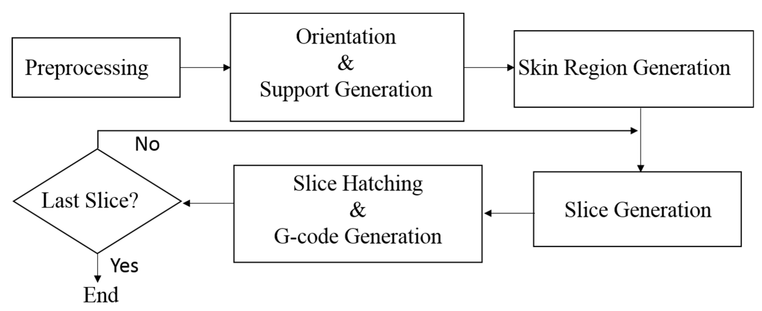
The architecture of the proposed G-code generator is shown in Figure 1. At first, the input model is preprocessed to remove dangling parts and noises. Then, the slicer orients the input model to maximize its stability, based on the inertia tensor of the input model. At the following computation, support structures of the model are generated by using a pattern-based method. After completing these computations, the slicer applies image processing operators to divide the foreground voxels into skin and internal regions. Then, the slicer cuts the model to create a 2D image; and this image is hatched to generate toolpaths by using depth-first search and texture mapping rasterization. In the following step, the resultant toolpaths are encoded into G-codes. The aforementioned slicing, hatching, and G-code encoding tasks are repeated until all layers of the input model have been processed and converted into G-codes.
The proposed slicer aims at translating volumetric models into G-codes. If the input model is expressed in a polygon-based representation, for example an STL file, a voxelization program is invoked to convert the input model into a 3D image at the preprocessing stage. If the input model is a volumetric one, image resampling may be required to synchronize the resolution of the input model and the nozzle diameter of the 3D printer. Tissues and organs segmented from medical image data sets may contain dangling fragments, small holes, narrow gaps, and broken structures, which are impossible to fabricate by 3D printers. If so, morphological operations, for example closing and opening, are performed to improve the quality of the volumetric model. After this preprocessing step, the input data become a 3D binary image, in which the foreground voxels constitute the model and the background voxels form the void space. Then, this 3D image is sent into the G-code generation pipeline for further processing.
3.2. Orientation
In an LM process, selecting a good printing direction may improve the fabrication time, surface quality, mechanical strength, and support structures of the finished part [19,20]. Hence, orientation is important for LM. However, the aforementioned criteria are mutually conflicted [18]. Finding a printing direction to optimize all these factors is, thus, impractical. In the proposed slicer, we oriented the model to maximize its stability such that its height and build time were reduced. Intuitively, a stable model needs less support structures than an unstable one. Thus, our orientation method may also reduce the volume of support structures [20].
In dynamics, the moment of inertia is used to measure how large a torque is required to rotate an object [21]. (The magnitude of the torque is linearly dependent on the moment of inertia.) In this work, we explored the mass distribution of the input model to find a direction, in which the moment of inertia of the input model is maximized. We treated this direction as the printing direction. Therefore, the model will attend maximum stability during the printing process.
Besides using the moment of inertia to find the printing direction, we regarded the orientation procedure as a coordinate system transformation process. In this work, we assumed that the origin of the input model space was at (0, 0, 0), and the voxels were at the grid points of a 3D lattice and can be indexed by (i, j, k). At first, the mass center, G, of the input model is computed:
where M represents the mass of the input model, Vi,j,k is the coordinates of the voxel at grid point (i, j, k), and ρi,j,k represents the mass of this voxel. If this voxel is a model voxel, then ρi,j,k is 1; otherwise, ρi,j,k is 0. Once G has been computed, the origin of the model space is shifted to G, and then the mass distribution of the input model is explored to calculate the new axes of the model space.
Since the input model may not be symmetric, its mass distribution should be expressed by an inertia tensor I [21]. The component tensors of the input model about G are calculated by
where x, y, and z stand for the shifted coordinates of the voxel indexed by (i, j, k). The inertia tensor of the input model is represented by the following matrix:
Then, we diagonalize I by using the Jacobi method [22],
where P is a column matrix of the principal axes of inertia, and D is a diagonal matrix of the principal inertias of the input model [21].
Then, we searched the principal axis associated with the maximum principal inertia. About this axis, we had to apply the largest torque to rotate the input model [21]. Hence, we chose this axis as the z axis such that the input model achieved the maximum stability. The other two principal axes were treated as the x and y axes of the new data coordinate system. Subsequently, we computed the extents of the input model in both the positive and negative z directions. If the extent in the negative z axis is longer than that in the positive z axis, we reverse the z axis to lower the vertical position of G to increase the stability of the input model. Once the new axes have been calculated, a rotational matrix is built by using the three axes to transform the positions of all voxels.
The example in Figure 2 shows the outcome of an orientation process. Part (a) shows the input volumetric model, while the oriented model is displayed in part (b). In these two images, the z axis is shaded in blue color and points vertically. Compared with the original model, the stability of the oriented model is increased, and the height of the oriented model is reduced from 207 to 116 voxels. (In this work, we measured the height and volume of a model in terms of voxels.) Thus, less layers would be produced in the hatching stage, and the build time would be reduced [20].
3.3. Support Structure Generation
In some LM processes, for example fused deposition modelling (FDM), support structures are needed to prevent the printed objects from collapsing during the printing stage. Many support structure generation techniques have been proposed for polygonal models [23,24]. Most of these methods explore the angles between the z axis and surface normal of the input model to detect supporting points and generate support structures. Since our input models are voxel-based, their support structures cannot be built by using these conventional methods. In this research, we developed a pattern-based method to produce support structures for volumetric models. At first, we found all the voxels in the input model that had no neighboring voxel immediately beneath them. We called these voxels the overhangs in this article. Secondly, we classified all overhangs into different types. Then, based on their types, necessary support structures were produced below the overhangs.
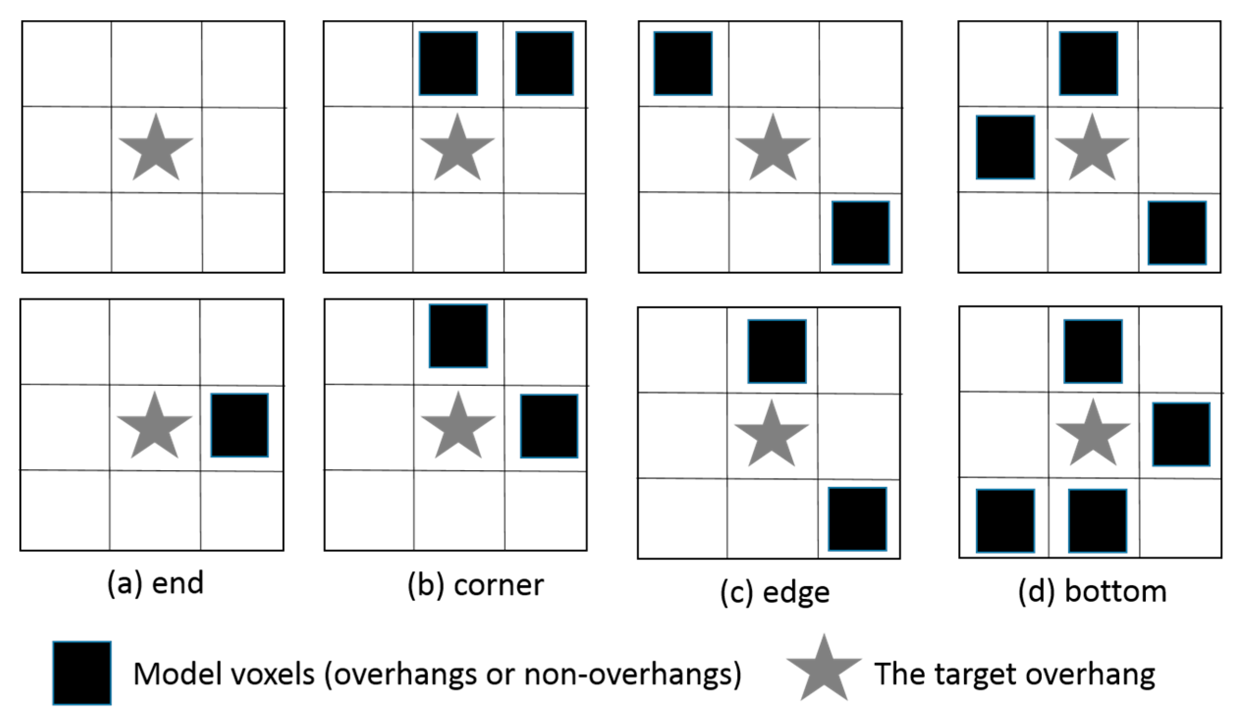
Our overhang classification method works as follows: Assume that the target overhang is at position (i, j, k). At first, we examined the 8 voxels residing at layer k − 1 and were adjacent to the overhang by sharing an edge or a vertex. If two or more of these neighbors are model voxels, this overhang would get enough support from them and this overhang is classified as supported. No support structure will be grown below it at the following stage. Otherwise, we check the 8 neighboring voxels residing at layer k and classify the overhang as an end, corner, edge, or bottom overhang according to predefined patterns. Some of these classification patterns are depicted in Figure 3. If this overhang has no more than 1 neighboring model voxel at layer k, as shown in part (a), it is classified as an end overhang. If it is on the boundary of the model and the acute angle around it is less than or equal to 90 degrees, this overhang is classified as a corner overhang as shown in part (b). If it is on the boundary and the acute angle is greater than 90 degrees, as depicted in part (c), this overhang is an edge overhang. If this overhang does not meet any of the above conditions, it is regarded as a bottom overhang as shown in part (d).
If the overhang is an end or a corner overhang, the cohesion between it and the neighboring vertex may not be strong enough to support it, and a vertical bar is placed under it. The top end of the bar reaches the overhang, and the other end of this pillar extends to the floor or the model’s surface. If the overhang is an edge or a bottom overhang, it has some support from its neighbors (because of cohesion). We do not have to create support structures for all of them. Instead, we select some of them as supporting points and build support bars beneath them. The selected overhangs should be away from other model voxels at the same layer by at least d voxels, where d is a constant decided by the users.
An example of support structure generation is shown in Figure 2. The support structures of the input model and the oriented model are shown in parts (c) and (d). The model voxels are rendered in red, while the support structures are shaded in dark green. The value of d is 4 voxels in this case. The support structures of the original model contain 67,388 voxels, while the support structures of the oriented model include only 50,390 voxels. In this case, our orientation program reduces the volume of the support structures by more than 25%.
3.4. Skin Separation and Slice Generation
In an LM process, the skin of the input model should be densely printed to produce a smooth surface, while the internal region is filled according to a predefined pattern to reduce the printing time and the weight of the physical object [25]. Thus, it is necessary to separate the skin and internal regions before carrying out the rest computations of the G-code generation process. To achieve this goal, our G-code generator repeatedly erodes the foreground voxels to generate the skin region. The number of erosions influences the skin region thickness [26]. More erosions result in a thicker skin region. In this work, we let the users to decide the number of erosions.
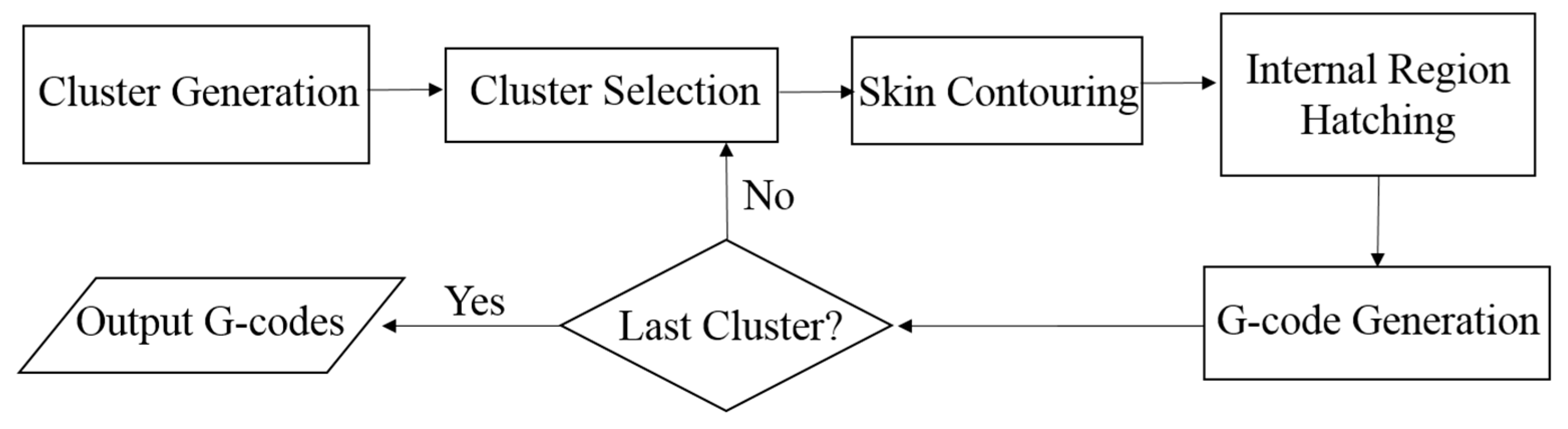
When a foreground voxel is eroded, its intensity is changed to a predefined value, dedicated to the skin region. Thus, the volume data set becomes a triple-valued 3D image after the skin region is generated. In the following computations, the input model is divided into slices along the z axis. The resultant slices are 2D images constituted by the void, skin, and internal pixels. The flowchart of converting a slice into G-codes is depicted in Figure 4. The skin and internal pixels may form several clusters in each individual slice, depending on the geometry of the input model. Thus, we have to group the foreground pixels into clusters by using a connected-component labelling scheme [26]. Then, these clusters are hatched one by one to generate toolpaths. As mentioned above, the skin and internal regions would be printed in different ways. Thus, the skin and internal pixels of each cluster will be rasterized by using different approaches. After the hatching process completes, the proposed slicer encodes the resultant toolpaths into G-codes and stores the G-codes in a disk file.
3.5. Skin Region Contouring
Since the skin region of the volume model would be thicker than one voxel, the skin region in a cluster of a 2D slice may be wider than a pixel. Thus, the skin region could be divided into multiple layers of contours. These contours are traced one after another to produce toolpaths for printing the skin region. To generate the first layer of contour, our slicer erodes the skin region at first. Then, the eroded pixels are treated as vertices, and an edge is drawn between two vertices if they are 8-connected [26] before the erosion. In such a way, a contour graph is built.
In the following step, a depth-first-search (dfs) [27] is performed to visit all vertices of the contour graph. The dfs may produce a cycle, a tree, or multiple trees, depending on the shape of the contour graph. The forward and backtracking paths of the dfs are recorded in linked lists. They are the toolpaths for printing the current contour. Once the first contour has been processed, the above computations are repeated until all the skin pixels have been rasterized and included in toolpaths.
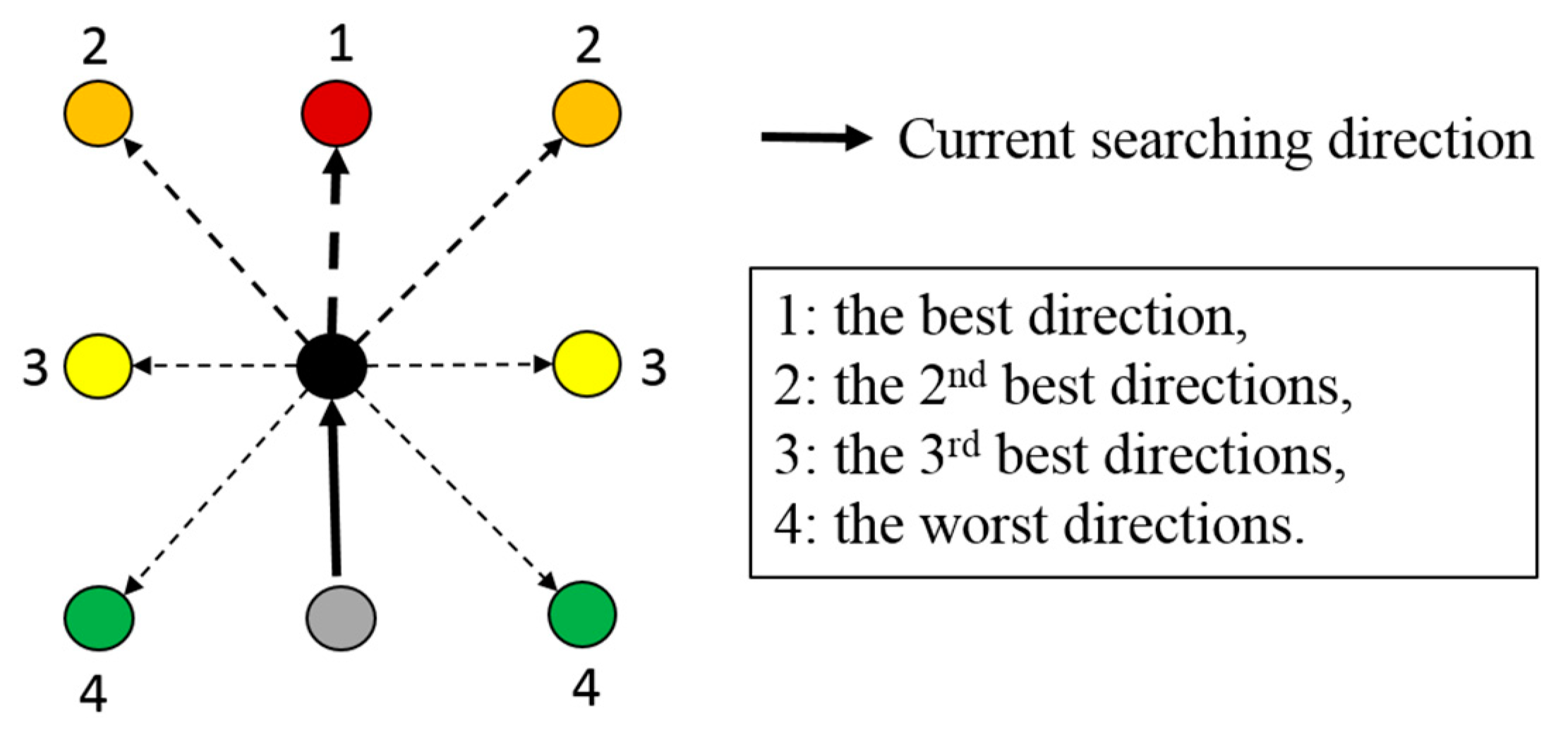
In the dfs, our slicer adopts a heuristic method to select marching directions to avoid generating short branches and staircases. The direction selection principle is illustrated in Figure 5. In the contour graph, a vertex has, at most, 8 neighbors. By ignoring the immediate predecessor in the dfs, our slicer has, at most, 7 directions to march forward from the current vertex. The direction from the immediate predecessor to the current vertex is regarded as the best direction to move forward, since it produces a straight path. If no vertex exists in this direction, our slicer examines the two adjacent directions. If any one of these two directions leads to an unvisited neighbor, the dfs continues in this direction such that the turning angle is minimized. Otherwise, the next two unvisited directions, adjacent to the previously examined two directions, are investigated. By following this principle, the searching process repeats until a direction is found or all the 7 directions have been tried. If forward-marching is impossible, our slicer backtracks to a vertex, in which a new branch can be grown, and starts to integrate a new branch from there.
3.6. Internal Region Hatching
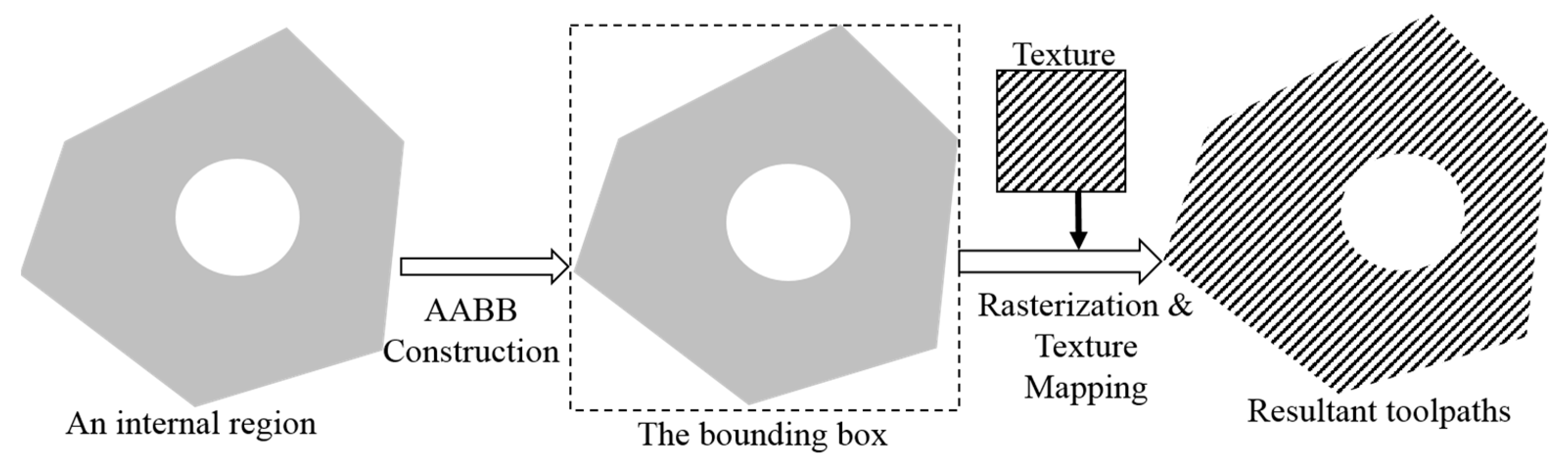
The proposed G-code generator adopts a texture-mapping method [28] to hatch the internal regions, as illustrated in Figure 6. Before hatching an internal region, an infilling pattern is selected from a set of textures by the users. The infilling pattern contains two types of texels: the space (zero) and the filling (nonzero) texels. Then, the axis-aligned bounding box (AABB) of the internal region is computed, and each corner of the AABB is given a pair of texture coordinates: s and t. In the following step, the AABB is rasterized in a scanline-by-scanline manner. During the rasterization, the texture coordinates of each pixel are calculated by using bilinear interpolation. Then, the void and skin pixels inside the AABB are ignored while the texture coordinates of each internal region pixel are used to retrieve a texel value from the infilling pattern. If the retrieved texel value is zero, the internal region pixel is converted into a void pixel. Otherwise, this internal region pixel is preserved. As the AABB has been rasterized, the remaining internal region pixels are connected to form one, or multiple, graphs and are traversed by using the dfs to produce toolpaths.
In the rasterization process of an internal region, users can rotate, scale, and shift the texture coordinates of the AABB to vary the orientation, repetition, and density of the infilling pattern. Thus, the mechanical strength of the printed object could be improved, and the weight of the printed object could be adjusted. Since the resolutions of the infilling pattern and the internal region may be different, filtering is required to alleviate alias in the hatching process. In this work, we adopted the nearest-point filter to compute the texel values of the pixels [28].
3.7. Toolpath and G-Code Generation
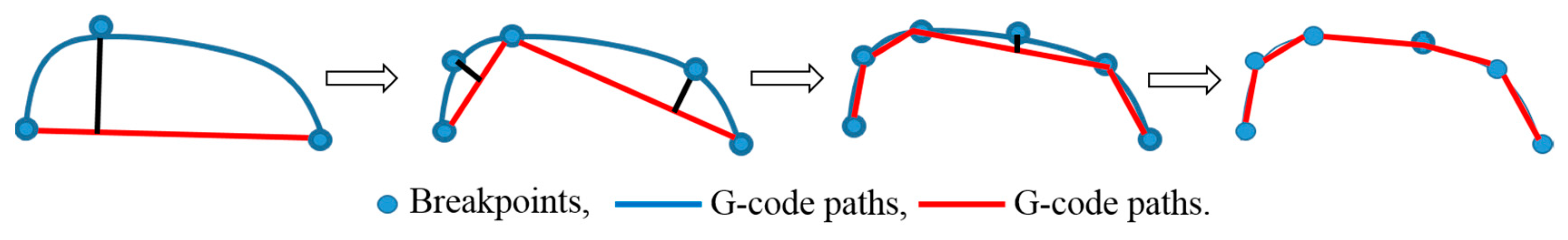
A toolpath produced by the dfs is a list of adjacent pixels. Unlike the toolpaths generated from a polygon-based model, this toolpath is not necessarily a straight line. Instead, it may contain many short zigzag segments of pixels. It should not be directly encoded into G-codes. Otherwise, too many G-codes will be produced, and the LM process would generate staircases on the surface of the printed part. An optimization algorithm is employed to smooth and encode the toolpath. The major goals of this algorithm include: (1) generating longer straight segments from the toolpath and (2) reducing the number of the zigzag segments. The proposed algorithm works as follows:
- Assume the toolpath is c(x,y);
- Create a straight line l(x,y) connecting the first and last pixels of c(x,y);
- Compute the maximum distance from each pixel of c(x,y) to l(x,y);
- If the maximum distance is greater than the threshold, break c(x,y) into c1(x,y) and c2(x,y) at the pixel where the maximum distance occurs (i.e., the splitting point). Then steps 2–4 are repeated upon c1(x,y) and c2(x,y) recursively;
- Otherwise, generate a G-code by using the coordinates of the first and last pixels of l(x,y).
An example is shown in Figure 7 to illustrate the aforementioned encoding method. The blue curve represents the toolpath c(x,y), the blue circles are the breakpoints, and the red lines represent the straight lines l(x,y), which approximate the toolpath.
4. Test Results
We implemented our slicer by using C-language and OpenGL libraries [28]. The resultant slicer contained three subsystems: a preprocessor, a G-code generator, and a visualization module. The preprocessor is responsible for voxelizing polygonal models into 3D images and filtering dangling parts and narrow gaps in volumetric models. The G-code generator is employed to translate voxel-based models into G-codes, while the visualization module is utilized to display the computational results of all stages in the G-code generation process. Several experiments have been carried out to evaluate our slicer. The results are presented and analyzed in this section.
4.1. Orientation and Support Structure Generation
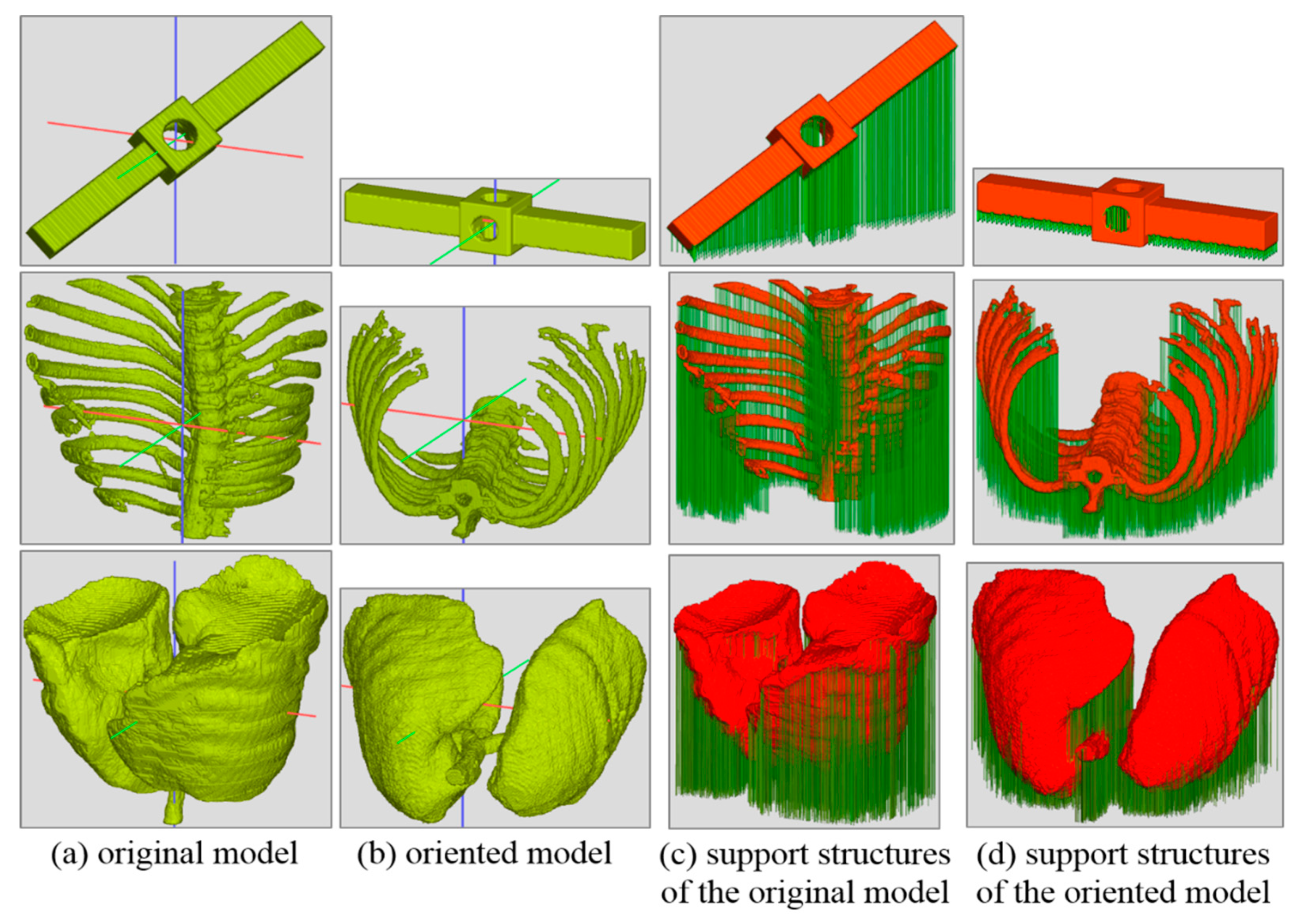
At first, we conducted a test to verify the effectiveness of our orientation algorithm and support structure generation method. Five volumetric models served as the input models in the test. We named these models stick, bone, lung, mushroom, and bonsai in this work. Three of them are shown in Figure 8a, including the stick, bone, and lung models (from the top to the bottom). The image of the mushroom model can be found in Figure 2a. The stick model is created by using a constructive solid geometry modeler. The bone and lung are segmented from a CT-scan data set. Originally, the mushroom is a polygonal model. We discretized it into a voxel-based representation by using the preprocessor of our slicer. Then, these models were oriented by our slicer. Parts of the results are shown in Figure 8b and Figure 2b. At the following step, support structures are generated for both the input and oriented models. The support structures of the stick, bone, and lung models are revealed in parts (c) and (d) of Figure 8, and the support structures of the mushroom are shown in Figure 2c,d.
To produce an objective comparison, the heights and the volumes of the support structures of the original and rotated models were calculated and recorded during the computations. The results are measured in voxels and are listed in Table 1. The first column contains the names of the models. The heights of the input and oriented models are recorded in the second and third columns, while the volumes of support structures of the input and oriented models are displayed in columns 4 and 5. As the numbers in column 2 and 3 show, the orientation process reduced the heights of these models. The height of the stick model was reduced by more than 72%, while the heights of other models were reduced by 17.6%, 21.2%, 44%, and 34%, respectively. Since the heights of these models were reduced, less slices will be produced in the following G-code generation process, and the build times of these objects will be decreased [20].
By maximizing their moments of inertia, the oriented models were more stable than the input geometries. They needed less support structures, as shown in columns 4 and 5 of Table 1. The stick model gained a significant improvement (more than 85%). The reductions of support structure for the other models were 18.9%, 15.6%, 33.7%, and 21.7%, respectively. By examining the images of Figure 2 and Figure 8, these improvements can also be visually verified. In these images, the x, y, and z axes of the data space are rendered in red, green, and blue colors. The z axis is pointed vertically, while these other 2 axes are rotated to reveal more details of the models. These images are produced by our visualization module using volume rendering.
4.2. The Printed Objects
These volumetric models were then converted into G-codes and manufactured by using an FDM 3D printer. The lung and bone models were much larger than the printing scope of the FDM printer. We had to scale them down before sending them into the G-code generation pipeline. The settings of the printing environment are depicted in Table 2. The nozzle diameter of the FDM printer was 0.4 mm. The layer thickness was 0.1 mm. The raw material was polylactic acid (PLA).
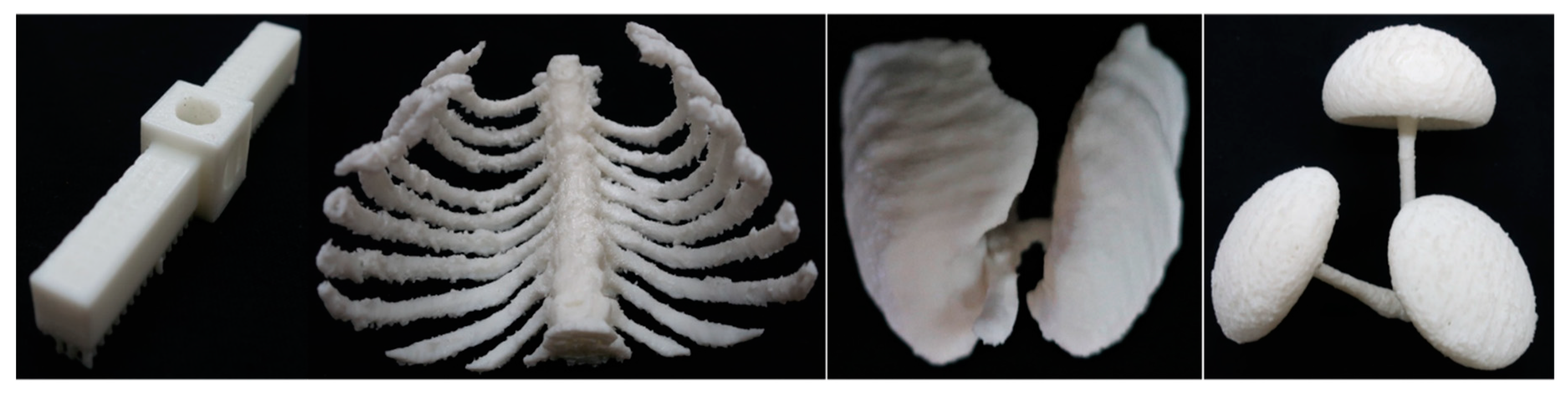
The images of the printed parts are shown in Figure 9. The printed bone, mushroom, lung, and stick models are shown in the images of the figure. The infilling pattern of internal region is a regular grid. The gridline space was about 1 mm. The dimensions of the bone, mushroom, lung, and stick models were 95 × 95 × 67, 97 × 84 × 46, 71 × 64 × 50, and 72 × 13 × 13 mm, respectively.
The bone model contained long slender parts. It needed many support structures, as shown in the second image of Figure 8d. As we removed the support structures, some parts of the printed object were damaged, as shown in Figure 9. The input mushroom model was created from a smooth surface model by using the voxelization program. Staircases prevailed in its surface, as shown in Figure 2a. The printed mushroom model shared this feature, but the staircases were reduced, as displayed in the right-most image of Figure 9. This verified that our toolpath encoding algorithm can alleviate saw-tooth effects. The lung model was segmented from a medical data set. Its surface was relatively smooth, as shown in Figure 8a. The printed lung model also possessed a high-quality outer appearance, as revealed in Figure 9. However, we were unable to remove some of the support structures because of occlusion. The stick model was well printed since its structure is simple. We kept its support structures to maintain its stability, as shown in the left-most image of Figure 9.
4.3. Visualization and User-Interferene
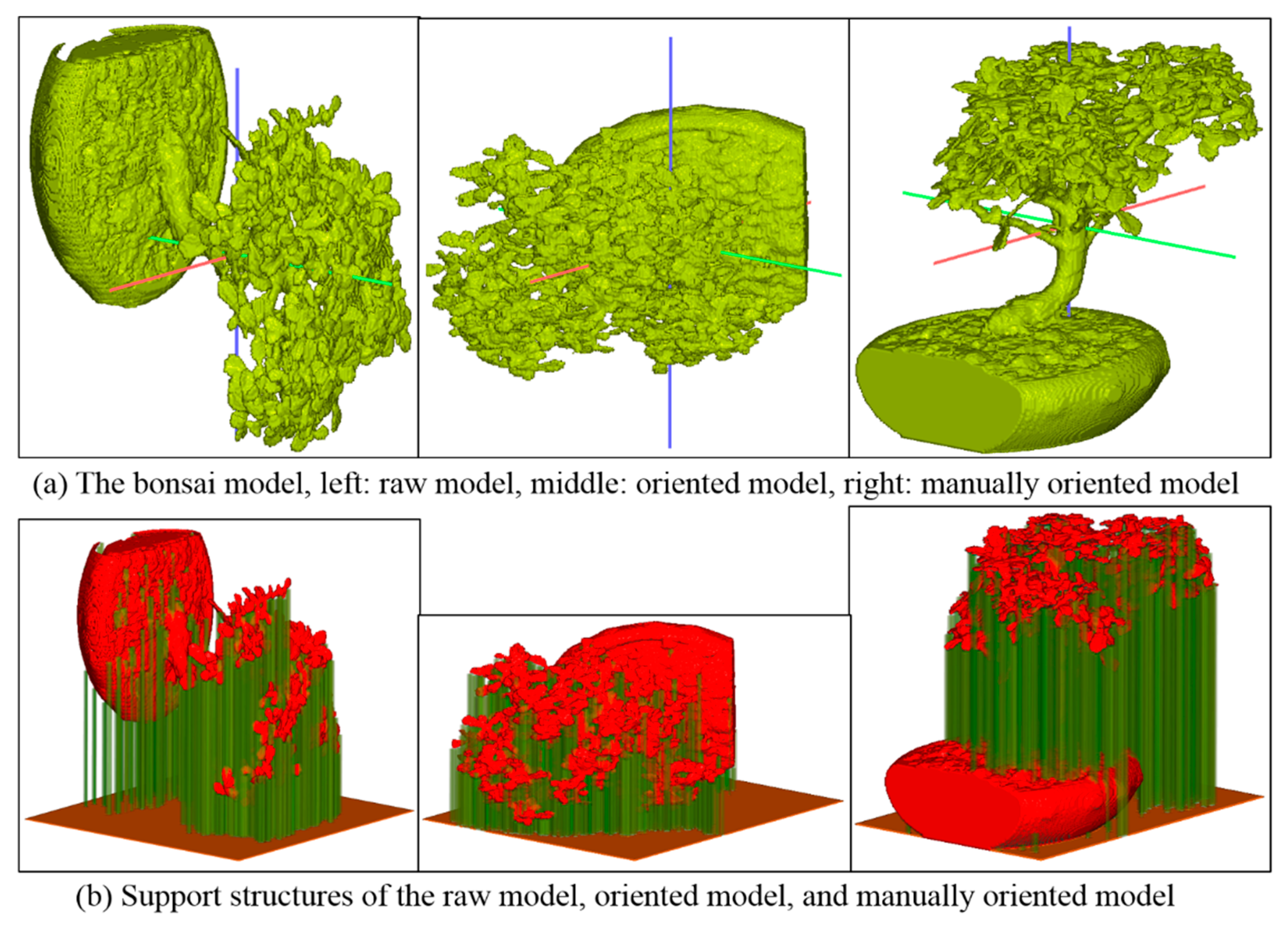
In an FDM LM process, removing the support structures from the printed part is sometimes difficult if the model is highly complex and fragile. To alleviate this difficulty, human experiences are superior to numerical and geometrical algorithms. Taking the bonsai model as an example, the oriented model needed less support structures, but removing the support structures from the printed part would be hard, as shown in the middle image of Figure 10b. If we chose the y axis as the printing direction, the model needed more support structures, but the postprocessing became easier, as shown in the right image of Figure 10b. Thus, we manually oriented the input model and selected the y axis as the printing direction.
For the purposes of debugging and previewing, we used our visualization module to render the toolpaths of each slice in an image. In the image, the void pixels are shaded in black color, while the toolpaths are represented by colorful lines. Eight slices of the bonsai model were retrieved from the visualization process and shown in Figure 11. The bonsai model had a complicated geometry, including the stem, branches, and leaves. Thus, it needed many support pillars, and each slice contained numerous pixel clusters as shown in these images. These images also reflected the variation of internal structure of the bonsai model along the z axis and helped us to comprehend the progression of the printing process.
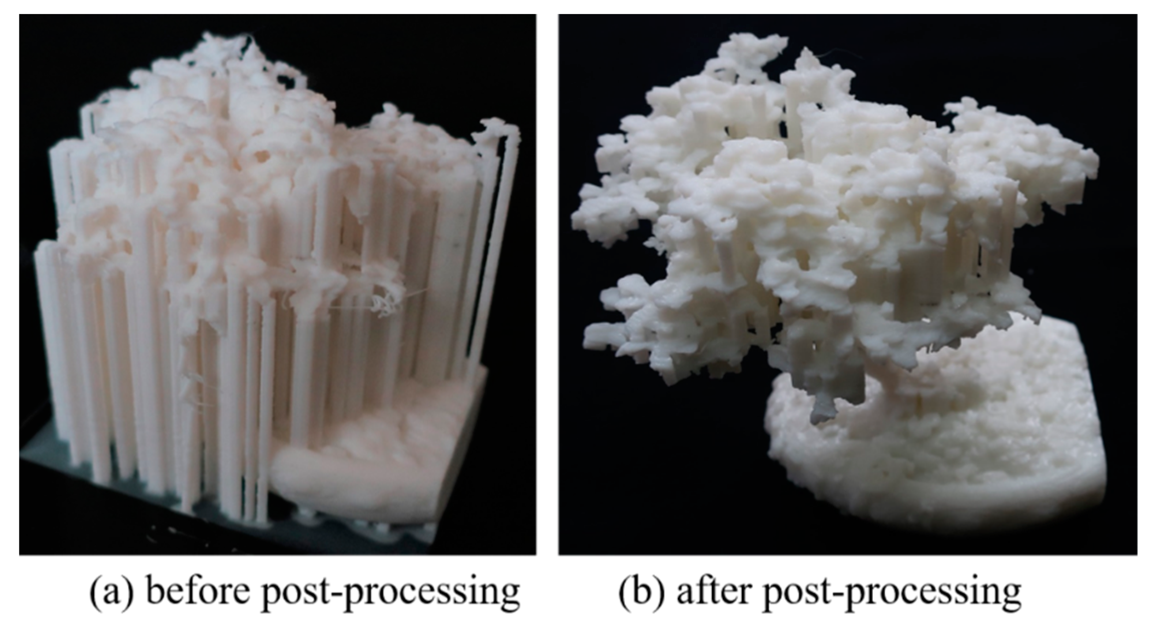
The printed results of the bonsai model are shown in Figure 12. The left image shows the physical model before the support structures were deleted, while the right image displays the bonsai model after some of the support structures have been removed. Since the bonsai model is very complicated, some of the support structures are hidden inside the models and are unable to be deleted. Thus, we kept them to avoid damaging the printed object.
5. Discussion and Implementation Issues
The extents of the lung and bone models exceeded the printing range of the FDM printer. We had to shrink these models in the LM processes. In a medical application, shrinking the input model to fit the printer’s range may be impractical. Instead, we should subdivide the input model into pieces to fit the printable scope of the printer. Besides fitting the printing range of the 3D printer, the subdivision process possesses extra benefits, for example, parallel printing, better orientation, and easier postprocessing.
In the future, we would like to conduct research to develop a subdivision algorithm for splitting large volumetric models into parts. The subdivision method should meet the following conditions:
- All the individual parts must fit the printable scope of the printer.
- The interfaces between the parts must be smooth enough for gluing the parts together.
- The interfaces must contain joints for connecting the parts.
- The sizes of the parts should be approximately equal.
6. Conclusions
In this article, we proposed a slicer to transform voxel-based geometric models into G-codes. Our slicer shares a similar G-code generation pipeline with conventional slicers. However, its major computational algorithms are innovative. The preprocessing, orientation, and support structure generation methods of our slicer are newly designed. Hatching each slice of a voxel-based model is very different from that of a polygonal model. Thus, innovative algorithms were developed in the proposed slicer to fulfill the duties. Test results revealed the efficiency of the proposed slicer. It successfully produced high-quality G-codes for both volumetric and polygonal models. But, the postprocessing of the printed objects may pose difficulties to us if the input models are complicated. Users’ interferences at the orientation stage can simplify the postprocessing task. The size of the input model causes another problem if it is larger than the printing range of the 3D printer. A good subdivision program can help our slicer conquer this obstacle in the future.
Author Contributions
Conceptualization, S.-K.U.; methodology, S.-K.U.; software, S.-K.U., H.-K.H. and H.-C.H.; validation, S.-K.U., H.-C.H. and S.-K.U.; investigation, S.-K.U.; resources, S.-K.U. and H.-C.H.; data curation, S.-K.U.; writing—original draft preparation, S.-K.U.; writing—review and editing, S.-K.U.; visualization, S.-K.U. and H.-C.H.; supervision, S.-K.U.; project administration, S.-K.U.; funding acquisition, S.-K.U.
Funding
This research was funded by the Ministry of Science and Technology, Taiwan ROC, grant number 104-2221-E-019-051.
Acknowledgments
The authors would like to thank National Taiwan Ocean University for offering us the testing facilities.
Conflicts of Interest
The authors declare no conflict of interest.
References
- Huang, S.H.; Liu, P.; Mokasdar, A.; Hou, L. Additive manufacturing and its societal impact: A literature review. Int. J. Adv. Manuf. Technol. 2013, 67, 1191–1203. [Google Scholar] [CrossRef]
- Pandey, P.M.; Reddy, N.V.; Dhande, S.G. Slicing procedures in layered manufacturing: A review. Rapid Prototyp. J. 2003, 9, 274–288. [Google Scholar] [CrossRef]
- Kamble, P.S.; Khoje, S.A.; Lele, J.A. Recent Developments in 3D Printing Technologies. In Proceedings of the IEEE International Conference on Intelligent Computing and Control Systems, Madurai, India, 14–15 June 2018; pp. 468–473. [Google Scholar]
- Mancas, M.; Gosselin, B.; Macq, B. Segmentation using a region-growing thresholding. Image Process. Algorithms Syst. IV 2005, 5672, 388–398. [Google Scholar]
- Chandru, V.; Manohar, S.; Prakash, C.E. Voxel-based modeling for layered manufacturing. IEEE Comput. Graph. Appl. 1995, 15, 42–47. [Google Scholar] [CrossRef]
- Wang, H.; Luo, F.; Jiang, J. 3D reconstruction of CT images based on isosurface construction. In Proceedings of the IEEE International Conference on Intelligent Computation Technology and Automation, Hunan, China, 20–22 October 2008. [Google Scholar]
- Ueng, S.K.; Huang, H.C.; Chou, C.S. Rapid prototyping of medical image data based on distance field concept. In Proceedings of the IEEE International Conference on Applied System Invention, Chiba, Japan, 13–17 April 2018. [Google Scholar]
- Brown, A.C.; de Beer, D. Development of a stereolithography (STL) slicing and G-code generation algorithm for an entry level 3-D printer. In Proceedings of the IEEE AFRICON, Pointe-Aux-Piments, Mauritius, 9–12 September 2013. [Google Scholar]
- Tata, K.; Fadel, G.; Bagchi, A.; Aziz, N. Efcient slicing for layered manufacturing. Rapid Prototyp. J. 1998, 4, 151–167. [Google Scholar] [CrossRef]
- Hiller, J.; Lipson, H. Design and analysis of digital materials for physical 3D voxel printing. Rapid Prototyp. J. 2009, 15, 137–149. [Google Scholar] [CrossRef]
- Tedia, S.; Williams, C.B. Manufacturability analysis tool for additive manufacturing using voxel-based geometric modeling. In Proceedings of the 27th Annual International Solid Freeform Fabrication Symposium, Austin, TX, USA, 8–10 August 2016. [Google Scholar]
- Ueng, S.-K.; Chen, L.-G.; Jen, S.-Y. Voxel-based virtual manufacturing simulation for three-dimensional printing. Adv. Mech. Eng. 2018, 10. [Google Scholar] [CrossRef] [Green Version]
- Rengier, F.; Mehndiratta, A.; Von Tengg-Kobligk, H.; Zechmann, C.M.; Unterhinninghofen, R.; Kauczor, H.-U.; Giesel, F.L.; Tengg-Kobligk, H. 3D printing based on imaging data: Review of medical applications. Int. J. Comput. Assist. Radiol. Surg. 2010, 5, 335–341. [Google Scholar] [CrossRef] [PubMed]
- Kitsakis, K.; Alabey, P.; Kechagias, J.; Vaxevanidis, N. A Study of the dimensional accuracy obtained by low cost 3D printing for possible application in medicine. IOP Conf. Ser. Mater. Sci. Eng. 2016, 161, 012025. [Google Scholar] [CrossRef]
- Giannopoulos, A.A.; Chepelev, L.; Sheikh, A.; Wang, A.; Dang, W.; Akyuz, E.; Hong, C.; Wake, N.; Pietila, T.; Dydynski, P.B.; et al. 3D printed ventricular septal defect patch: A primer for the 2015 Radiological Society of North America (RSNA) hands-on course in 3D printing. 3D Print. Med. 2015, 1, 3. [Google Scholar] [CrossRef] [PubMed]
- Alabey, P.; Pappas, M.; Kechagias, J.; Maropoulos, S. Medical Rapid Prototyping and Manufacturing: Status and Outlook. In Proceedings of the ASME 10th Biennial Conference on Engineering Systems Design and Analysis, Istanbul, Turkey, 12–14 July 2010; pp. 739–745. [Google Scholar]
- Littley, S.; Voiculescu, I. Interpolation of 3D slice volume data for 3D printing. In Proceedings of the Medical Imaging 2017: Image-Guided Procedures, Robotic Interventions, and Modeling. International Society for Optics and Photonics, Orlando, FL, USA, 11–16 February 2017. [Google Scholar]
- Oropallo, W.; Piegl, L.A. Ten challenges in 3D printing. Eng. Comput. 2016, 32, 135–148. [Google Scholar] [CrossRef]
- Pandey, P.; Reddy, N.V.; Dhande, S. Part deposition orientation studies in layered manufacturing. J. Mater. Process. Technol. 2007, 185, 125–131. [Google Scholar] [CrossRef]
- Kechagias, J.; Anagnostopoulos, V.; Zervos, S.; Chryssolouris, G. Estimation of build times in rapid prototyping processes. In Proceedings of the 6th European Conference on Rapid Prototyping & Manufacturing, Nottingham, UK, 1–3 July 1997; pp. 137–148. [Google Scholar]
- Hibbeler, R.C. Engineering Mechanics Dynamics, 14th ed.; Pearson: London, UK, 2017; pp. 591–596. [Google Scholar]
- Golub, G.H.; Van Loan, C.F. Matrix Computations, 2nd ed.; The Johns Hopkins University Press: Baltimore, MD, USA, 1989; pp. 409–474. [Google Scholar]
- Kruth, J.-P.; Leu, M.; Nakagawa, T. Progress in Additive Manufacturing and Rapid Prototyping. CIRP Ann. 1998, 47, 525–540. [Google Scholar] [CrossRef]
- Vanek, J.; Galicia, J.A.G.; Benes, B. Clever Support: Efficient Support Structure Generation for Digital Fabrication. Comput. Graph. Forum 2014, 33, 117–125. [Google Scholar] [CrossRef] [Green Version]
- Ma, W.; He, P. An adaptive slicing and selective hatching strategy for layered manufacturing. J. Mater. Process. Technol. 1999, 89, 191–197. [Google Scholar] [CrossRef]
- Webb, A.; Kagadis, G.C. Introduction to Biomedical Imaging; John Wiley & Sons: Hoboken, NJ, USA, 2017. [Google Scholar]
- Horowitz, E.; Sahni, S.; Anderson-Freed, S. Fundamentals of Data Structures in C, 2nd ed.; Silicon Press: Summit, NJ, USA, 2007. [Google Scholar]
- Angel, E.; Shreiner, D. Interactive Computer Graphics—A Top-Down Approach, 6th ed.; Pearson Education Limited: London, UK, 2012. [Google Scholar]
Figure 1.
Pipeline of the proposed slicer.

Figure 2.
Orientation and support structure generation; (a) original model, (b) oriented model, (c) support structures (in green color) of the original model, and (d) support structures of the oriented model.
Figure 2.
Orientation and support structure generation; (a) original model, (b) oriented model, (c) support structures (in green color) of the original model, and (d) support structures of the oriented model.

Figure 3.
Classification patterns of overhangs: (a) end, (b) edge, (c) corner, and (d) bottom overhangs. The star represents the overhang to be classified, and the squares are its neighboring model voxels at the same layer. This figure shows only some representative patterns. Other patterns can be obtained by rotations or by analogy.

Figure 4.
Flowchart of G-code generation for a slice.

Figure 5.
Searching priorities in the depth-first-search on a contour graph.

Figure 6.
Internal region filling by using texture mapping. AABB, axis-aligned bounding box.

Figure 7.
Encoding a toolpath into a series of G-codes.

Figure 8.
Images of the stick, bone, and lung models; (a) the raw models, (b) oriented models, (c) support structures of the raw models, and (d) support structures of the oriented models.
Figure 8.
Images of the stick, bone, and lung models; (a) the raw models, (b) oriented models, (c) support structures of the raw models, and (d) support structures of the oriented models.

Figure 9.
Images of the printed objects; stick, bone, lung, and mushroom (from left to right).

Figure 10.
Images of the bonsai model: (a) the raw, oriented, and manually oriented models; (b) support structures of the raw, oriented, and manually oriented models.
Figure 10.
Images of the bonsai model: (a) the raw, oriented, and manually oriented models; (b) support structures of the raw, oriented, and manually oriented models.

Figure 11.
2D slices of the bonsai model and the toolpaths generated by the hatching process. The infilling pattern is a dense grid.
Figure 11.
2D slices of the bonsai model and the toolpaths generated by the hatching process. The infilling pattern is a dense grid.

Figure 12.
Printed results of the bonsai model, (a) before removing support structures and (b) after the postprocessing.
Figure 12.
Printed results of the bonsai model, (a) before removing support structures and (b) after the postprocessing.


Table 1.
Heights and volumes of support structures of the test data (measured in voxels).
| Data Sets | Height (in Voxels) | Volume of Support Structure | ||
|---|---|---|---|---|
| Original | Oriented | Original | Oriented | |
| Stick | 150 | 42 | 24,731 | 3632 |
| Bone | 324 | 267 | 499,806 | 405,050 |
| Lung | 316 | 249 | 239,469 | 202,182 |
| Mushroom | 207 | 116 | 67,388 | 50,390 |
| Bonsai | 256 | 169 | 1,311,485 | 1,026,258 |
Table 2.
Settings of the 3D printer.
| Parameters | Parameter Values |
|---|---|
| Layered manufacturing (LM) modality | Fuse deposition modelling (FDM) |
| Filament | Polylactic acid (PLA) |
| Nozzle diameter | 0.4 mm |
| Layer thickness | 0.1 mm |
| Nozzle temperature | 205 °C |
© 2019 by the authors. Licensee MDPI, Basel, Switzerland. This article is an open access article distributed under the terms and conditions of the Creative Commons Attribution (CC BY) license (http://creativecommons.org/licenses/by/4.0/).
Share and Cite
MDPI and ACS Style
Ueng, S.-K.; Huang, H.-K.; Huang, H.-C. A G-Code Generator for Volumetric Models. Appl. Sci. 2019, 9, 3868. https://doi.org/10.3390/app9183868
AMA Style
Ueng S-K, Huang H-K, Huang H-C. A G-Code Generator for Volumetric Models. Applied Sciences. 2019; 9(18):3868. https://doi.org/10.3390/app9183868
Chicago/Turabian StyleUeng, Shyh-Kuang, Hsuan-Kai Huang, and Hsin-Cheng Huang. 2019. "A G-Code Generator for Volumetric Models" Applied Sciences 9, no. 18: 3868. https://doi.org/10.3390/app9183868
Note that from the first issue of 2016, this journal uses article numbers instead of page numbers. See further details here.