Design and Research of a Flexible Foot for a Multi-Foot Bionic Robot


Department of Automation, Ocean University of China, Qingdao 266100, China
*
Author to whom correspondence should be addressed.
Appl. Sci. 2019, 9(17), 3451; https://doi.org/10.3390/app9173451
Submission received: 2 July 2019
/
Revised: 16 August 2019
/
Accepted: 16 August 2019
/
Published: 21 August 2019
Abstract
:To solve the problems of large landing impact, vibration, and poor adaptability to complex ground surfaces in the motion of a foot-type robot, a two-degree-of-freedom flexible foot-end structure was proposed and designed in this study. The effects of flexible materials, flexible parameters, and structural forms on the performance of the foot end have been discussed. Through simulation and experimentation, the parameter analysis and mechanical calibration of the foot end were completed, and a motion experiment of the flexible foot robot was designed. The simulation and experimental results showed that the flexible foot-end structure has uniform and reliable force and can effectively reduce the foot impact. Compared with the rigid foot, the foot-end force of the flexible foot was only 1/3 of the contact force, the peak foot pressure decreased by 59%, the motion stability increased by 37.4%, and the error of force perception was controlled at 11%. The flexible foot structure improved the stability of the robot motion process, reduced the vibration, provided the robot with good terrain adaptability, and achieved omnidirectional motion of the robot.
1. Introduction
Multi-legged robots are widely used in complex working environments due to their strong terrain adaptability and high flexibility [1,2]. However, there are many problems with these robots, such as large impact and limited operation space [3,4]. As robot technology develops toward achieving higher speeds and greater precision, the flexible effects of components are becoming more and more obvious [5,6]. Research on flexible materials and flexible mechanisms is of great significance in improving the service life, compliance control, stability, and terrain adaptability of legged robots [7,8]. Flexible structures and flexible materials have become an important direction for research on multi-legged robots [9].
In order to optimize the motion performance of the robot foot and reduce the impact between the foot and the ground [10,11], many research works have been conducted on flexible feet and flexible bionic joints. Kevin et al. designed and developed a hexapod robot leg structure that used the variable stiffness flexible leg “C-leg” to improve the robot’s bounce ability [12]. Hamill [13] and Guo [14], designed a flexible foot crawling robot that could buffer the impact between the foot and terrain and sense the ground environment. It was shown in Reference [15,16] that a passive buffer structure composed of linear springs was attached to the foot tip of the quadruped robot, which provided good buffering when the robot struck the ground. Riese et al. [17] designed a flexible leg model was designed to reduce the impact of the robot foot. Inspired by the biological system, the principle of binding force closure [18] simulates the muscle tension of animal legs and improves the stability of the robot’s bouncing movement.
By analyzing the motion pattern of the insect foot during its landing stage, it has been found that an insect’s movement process can be divided into two stages: (1) the claw with the claw pad is in contact with the ground, the deformation of the claw pad adapts to the complex terrain, and the impact force of the claw in contact with the ground is slowed down; and (2) by the flexible membrane between the connecting claw and the tarsus, a contraction of the sacral joint is made to open all the claws, and the knuckles and the claws are completely in contact with the ground, thereby increasing the contact area. The flexible membrane serves to attenuate the impact force and protect the joints of the legs [19]. Many attempts have been made by experts at home and abroad to use flexible materials to absorb the impact force [20,21]. It was shown in Reference [22] that a new structure was proposed to absorb the impact force with a combination of wheel, intermediate, and stabilizer. Sun, Ling et al. [23,24] show that by compensating the flexible structure with a control algorithm, the errors caused to the robot system by the flexible structure were reduced. The structure designed in Reference [25] can well realize mechanical information perception. It was shown in Reference [26,27] that carried out research on the acquisition method and signal transmission mode of force signals that has great innovative significance and provided us with a good idea.
Therefore, this study drew on the bionics analysis results to design and manufacture a flexible, two-degrees-of-freedom foot unit. When the foot strikes the ground, the flexible sole deforms to adapt to complex terrain while reducing the impact force, and the force is then transmitted to the compression spring through the push–pull rod to achieve secondary absorption of the impact force. The flexible sole was made by 3D printing mold-casted silicone, and the other modules of the flexible foot were 3D printed using photosensitive resin. The effects of the flexible materials, flexible parameters, and structural forms on the performance of the foot end were analyzed by simulation and experimentation. Force analysis and flexible foot-end force calibration were carried out for the foot tips. A motion contrast experiment between a flexible foot and a full rigid structure foot end was designed. The experimental results showed that the flexible foot designed in this study can effectively reduce impact force, improve the stability of the robot’s motion, and offer good terrain adaptability.
The rest of the paper is organized as follows: Section 2 mainly introduces the mechanical structure of the flexible foot and the related parameters of the main components. Section 3 analyzes the mechanical properties of the foot end. Section 4 calibrates the flexible foot mechanism. Section 5 shows the design of the prototype experiment. The experimental results have been analyzed, and the final conclusion is presented in Section 6.
2. Flexible Foot Mechanism Design
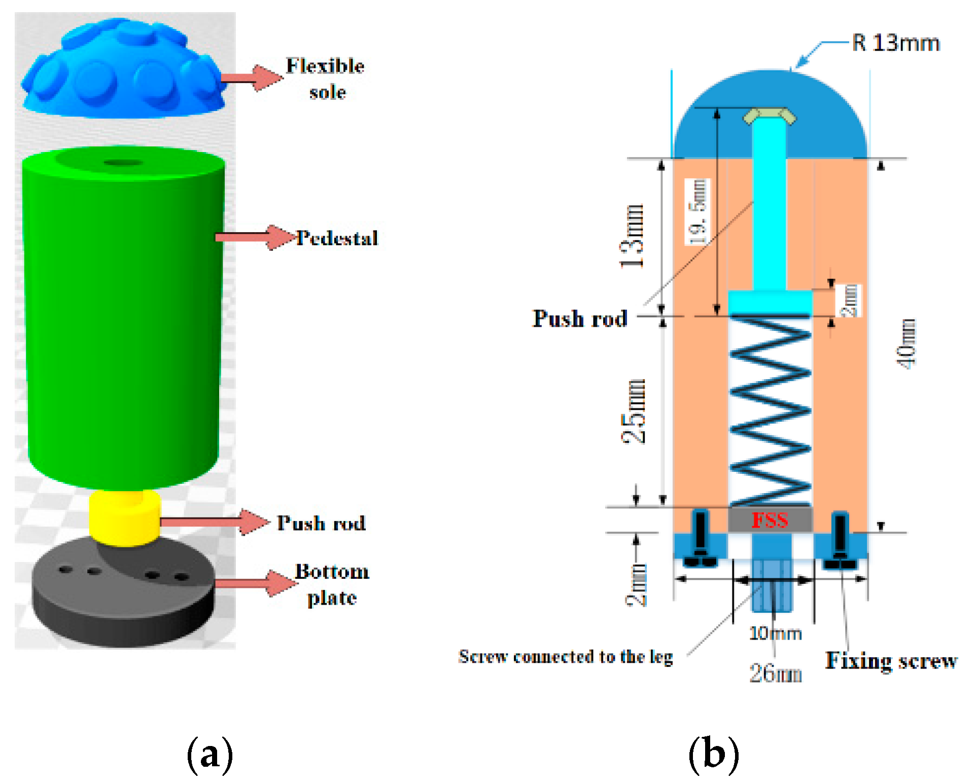
According to the principles of bionics, we designed the flexible foot unit to mimic the composition and movement characteristics of an insect’s foot. The robot’s foot end first absorbs the terrain through the flexible sole, slows the contact impact between the legs and the ground, and then weakens the impact by the spring mechanism, achieving secondary absorption of the impact force. According to this principle, a two-degrees-of-freedom foot mechanism, as shown in Figure 1, was designed. The mechanism consisted of six parts: a flexible sole, a base, a push–pull rod, a compression spring, a pressure sensor, and a bottom plate. The pedestal, the bottom plate, and the sole mold were made from photosensitive resin using 3D-printing technology, and the printing precision was 0.1 mm. After the foot mold was printed, the flexible robot foot was formed by injecting silica gel HC9000 (Shinebon Company in Anhui Province, China. HC9008 and HC9015 mentioned below are produced by the same company). The diameter of the foot tip was 13 mm, the height of the base was 40 mm, and the overall mass was 45 g.
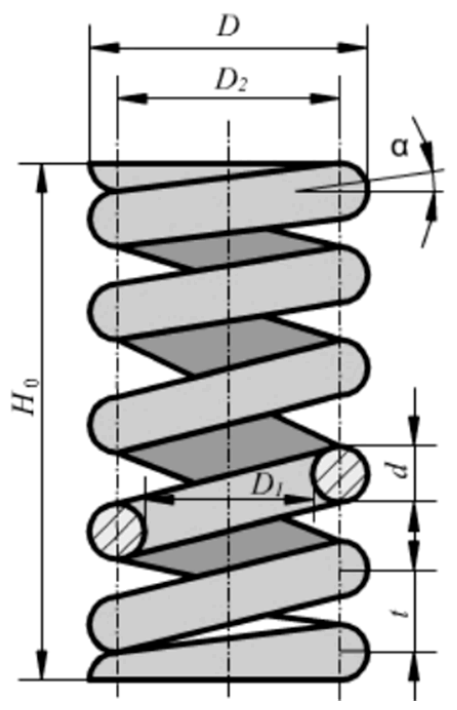
The rationality of the spring directly determines the motion performance of the entire foot mechanism. Therefore, the spring was designed in detail. The structure of the spring is shown in Figure 2. The parameters are shown in Table 1. The small hexapod robot used in the experiment had a single leg support force of less than 10 N, and, considering the low stress factor, the selected spring material was a B-grade carbon spring steel wire, and the tensile strength limit of was obtained. The maximum stroke was ; the outer diameter D was 8 mm; the maximum load was about ; the minimum was ; the spring ends were flattened; and the number of support turns was one turn. Other parameters are listed below:
- Spring wire diameter D:
- Elastic coefficient K, effective number of turns N:
- Total number of laps:
Total load shape variable:
Pressure height:
Freedom height:
Pitch:
After selecting a suitable compression spring, a Honeywell FSS (Honeywell in Morris town, New Jersey, USA) pressure sensor was placed between the compression spring and the bottom plate. When the flexible material is deformed by force, the push–pull rod passes through the spring structure and finally acts on the FSS pressure sensor. The foot-end force information is fed back through the pressure sensor in real time. This can effectively improve the environmental adaptability and stability of the robot in complex terrain.
3. Analysis of Mechanical Properties of the Foot End
Foot Force Analysis
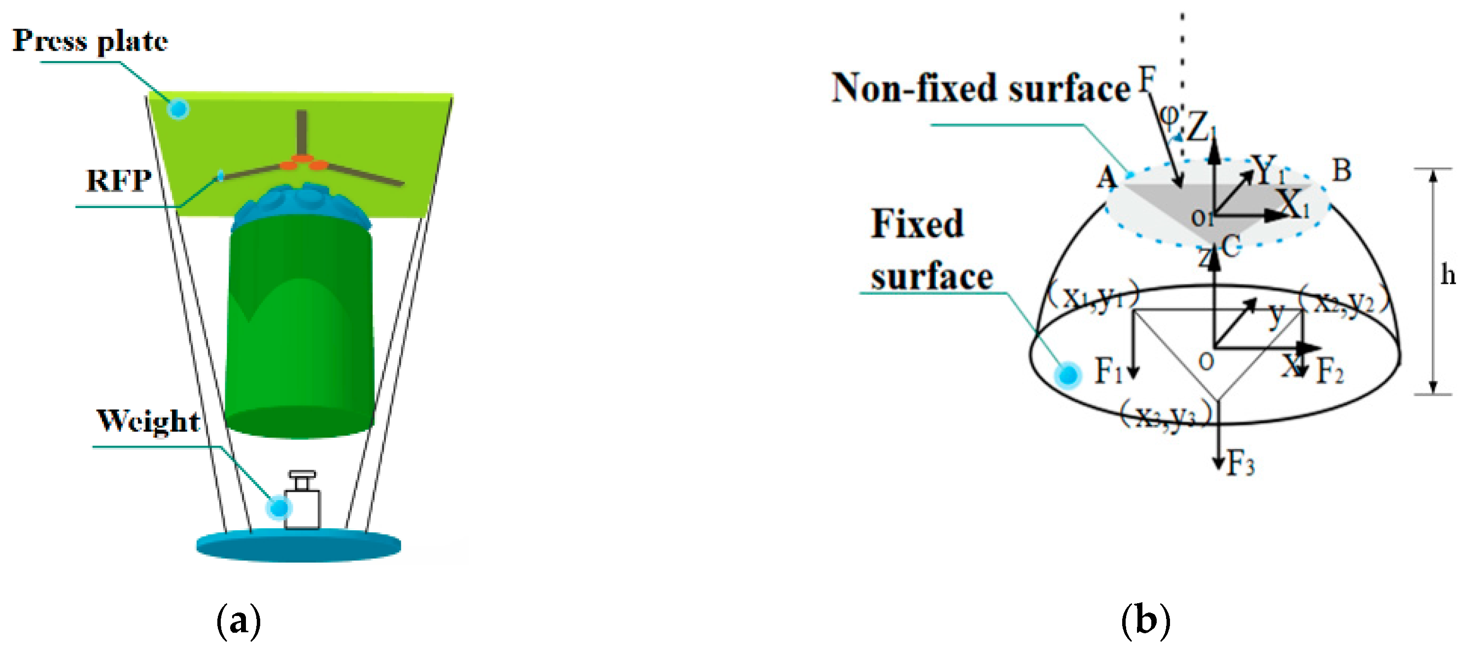
As shown in Figure 3, in order to facilitate the analysis of the foot-end force, three RFP (Yubo Intelligent Technology Co., Ltd. in Hangzhou, China.) film pressure sensors were placed at the contact plane between the foot end and the pressure plate. The main function of the three sensors was to perform data calculation and parameter identification. As shown in Figure 3a, each of the three sensors was at an angle of 120°. The force model is shown in Figure 3b. The fixed surface was linked to the FSS pressure sensor through the push–pull rod. The non-fixed surface contacted the ground to form a deformation. This was equivalent to a spring with a spring constant of k2. A fixed surface coordinate system O and a non-fixed surface coordinate system O1 were established as shown in the figure. When the foot was perpendicular to the ground, the two coordinate systems were in the same direction, and the length of the flexible material in the natural state was h. When the force was applied in the vertical direction, we assumed the projection positions of the three RFP film pressure sensors on the fixed surface were (x1, y1), (x2, y2), and (x3, y3), the fixed surface forces are F1, F2, and F3, and the coordinates of the three points corresponding to the non-fixed surface were A (x1, y1, h − F1/k2), B (x2, y2, h − F2/k2), and C (x3, y3, h − F3/k2).
The torque of F1 to O1 is:
where z1 = 0, F1x + F1y = 0, and F1z = F1, so
Similarly, the combined torque of the three RFP film pressure sensors is
The combined torque is
The angle between the direction of the force and the x-axis is
The joint force is
Take three non-collinear vectors in a non-fixed plane:
Let the normal vector of the non-fixed surface be
Thus:
Namely:
Solved equations can be obtained as follows:
The angle between the normal vector and the z-axis is obtained as follows:
The relationship between the positive pressure on the fixed surface on the z-axis and the positive pressure on the sole F is as follows:
The sole torque is still M. The theoretical value of the force relationship of the flexible material of the foot can be obtained from the above formula. At the same time, this section also gives the theoretical value relationship between the force and the angle between the sole force and the z–axis of the fixed surface, which provided the basis for the subsequent force calibration of the foot end.
4. Flexible Foot Mechanism Calibration
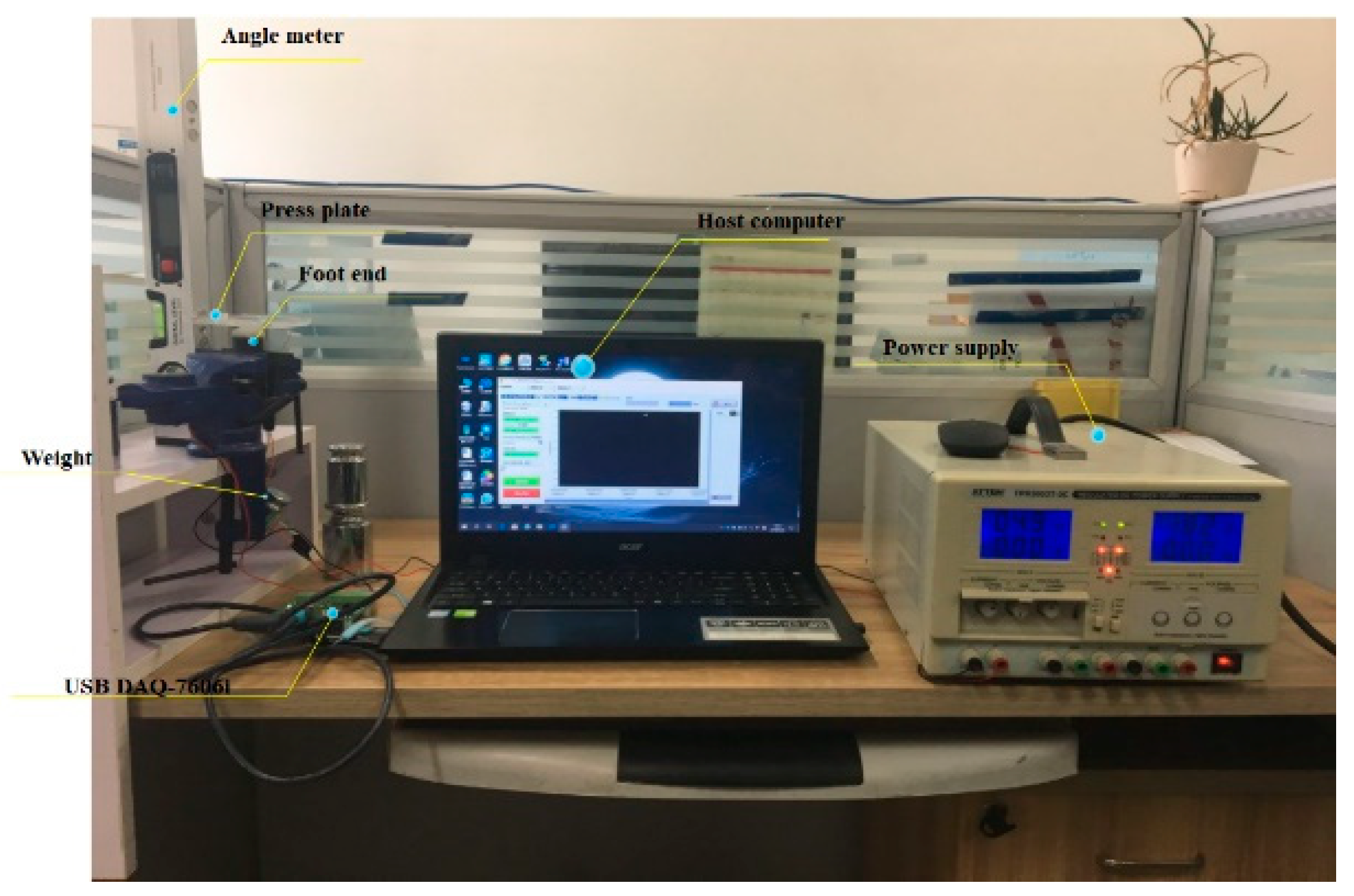
In this section, the omnidirectional force calibration experiment of the foot mechanism was designed, and the experimental calibration of different materials, different force directions, and different stress points was carried out. The experimental platform is shown in Figure 4. The output signal of the foot mechanism was collected by the data acquisition card USB DAQ–7606i, and the sampling gain was set to 1. In the input range of −10 V to +10 V, the measured voltage value error was controlled below 1 mV. The sampling frequency was set to 10 sps (samples per second), and the collected voltage data were uploaded to the host computer for data processing through the USB. The DC stabilized power supply provided a stable 5 V DC voltage for the FSS pressure sensor.
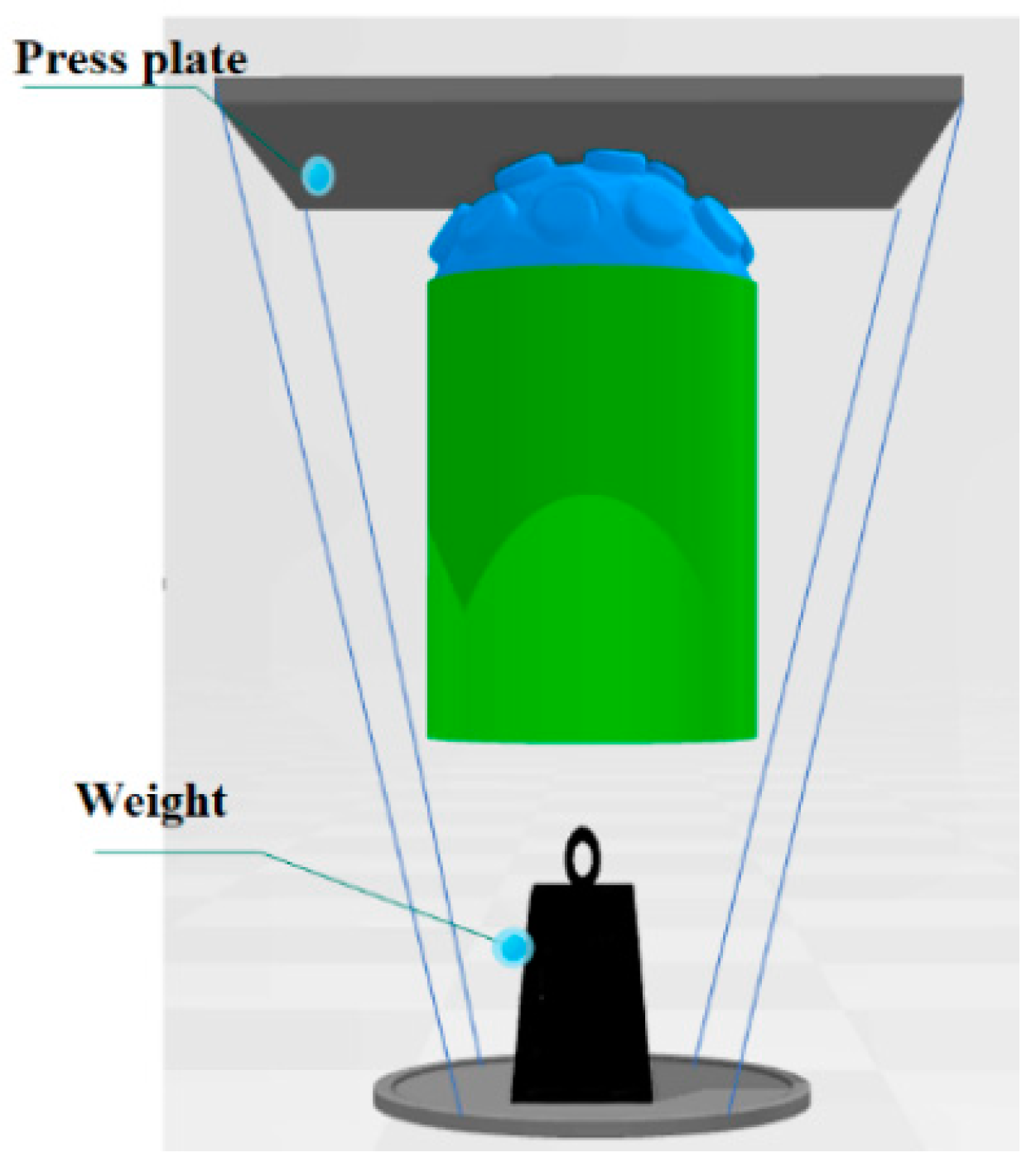
The experimental principle is shown in Figure 5. When measuring the force at different angles, the foot mechanism was fixed on the angle meter. The angle meter was used to record the angle change of the foot tips when different weights were fixed under the square pressure plate. Changing the mass of the weight changed the force on the foot, and the design of the calibration platform ensured uniform exertion of force on the foot. The device was used for flexible material stress calibration and omnidirectional force calibration.
4.1. Different Flexible Materials Foot Force Calibration
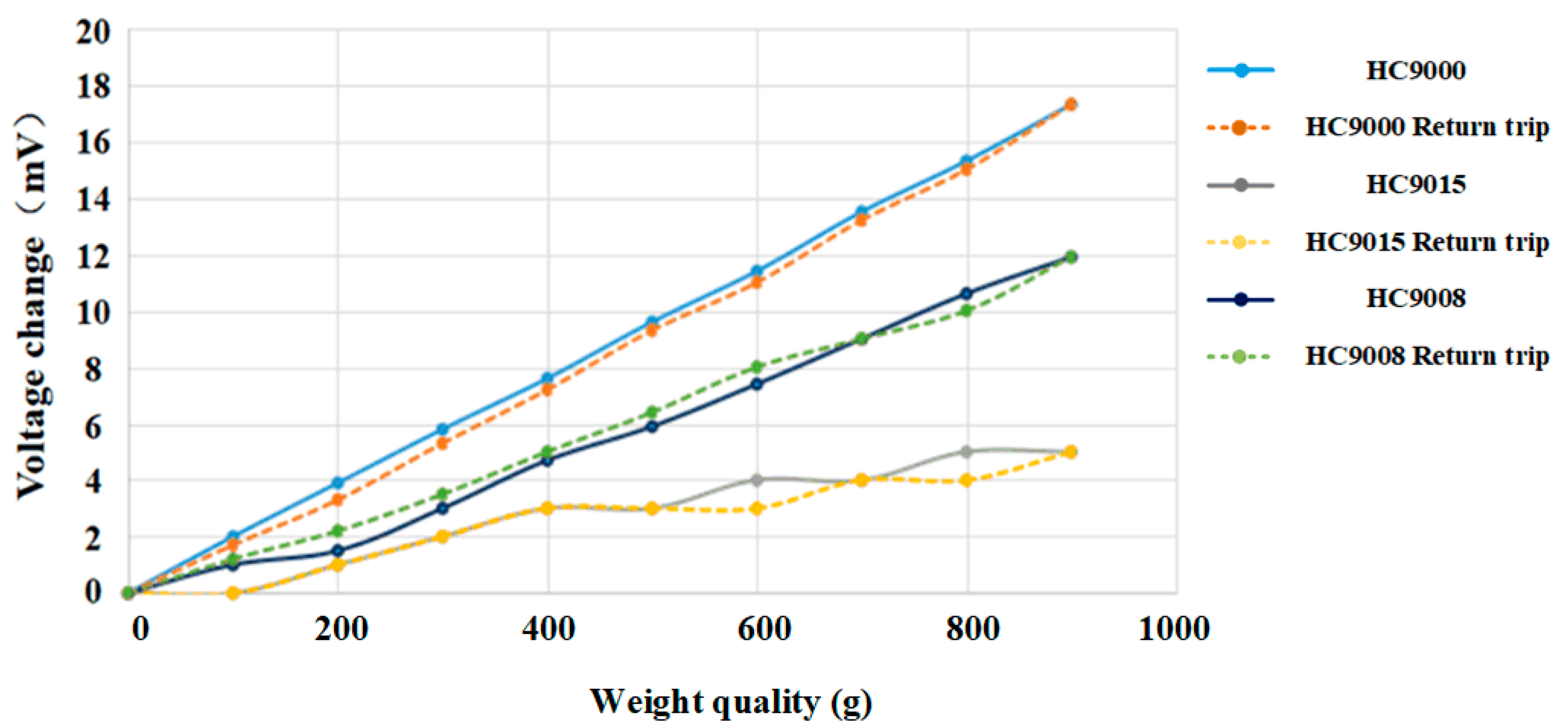
This section describes a comparative analysis of three materials to determine the effects of flexible materials on the perceived force performance of the foot mechanism. The selected three types of silicone rubbers, HC9000, HC9008, and HC9015, were injected into separate foot molds to cure, and the other parameters were the same, except for the materials. For each material, the foot tip was fixed, the direction of the force was fixed, only the quality of the weight (As shown in Figure 5) was changed, and the change of the voltage value of the foot tip was recorded. Three groups of each material were subjected to the force test, and the average experimental results are shown in Figure 6. The solid line is the forward stroke of the weight increase, and the dashed line is the reverse stroke of the weight reduction.
It can be seen from the figure that under the same external force, the material with the smallest hardness, HC9000, had the largest voltage variation, and the voltage variation was basically linear with the pressure received. The reverse stroke was more obvious, which was better than the linear relationship of HC9008; for HC9015, when the mass of the weight was greater than 400 g, the flexible foot shape variable of HC9015 was saturated due to the shape of the foot end. As the mass of the weight increased, the voltage variation decreased.
The voltage variation ΔU of the FSS pressure sensor was proportional to the pressure Fss received, namely,
where ΔU is the output voltage, k is the force–voltage conversion coefficient, and k = 6 mV/N was measured at no load. In the force range of the robot foot end 0–10 N, the force acting on the flexible material is FN, and the force of the pressure sensor FSS is Fss. The following observations can be made from Figure 6:
- When pressure was applied to the HC9000 material,
- When pressure was applied to the HC9008 material,
- When the pressure was applied to the HC9015 material, the relationship was not obvious.
Therefore, when the hardness of the flexible material was within a certain range, it could effectively reduce the falling impact between the foot tip and the ground. Combined with the analysis of flexible materials in the previous section, it can be seen that compared with HC9008, the mass of the robot was known, and within the range of 0–10 N, the HC9000 could reach its own yield limit, and the foot end force was 1/3 of the contact force.
4.2. Omnidirectional Force Calibration
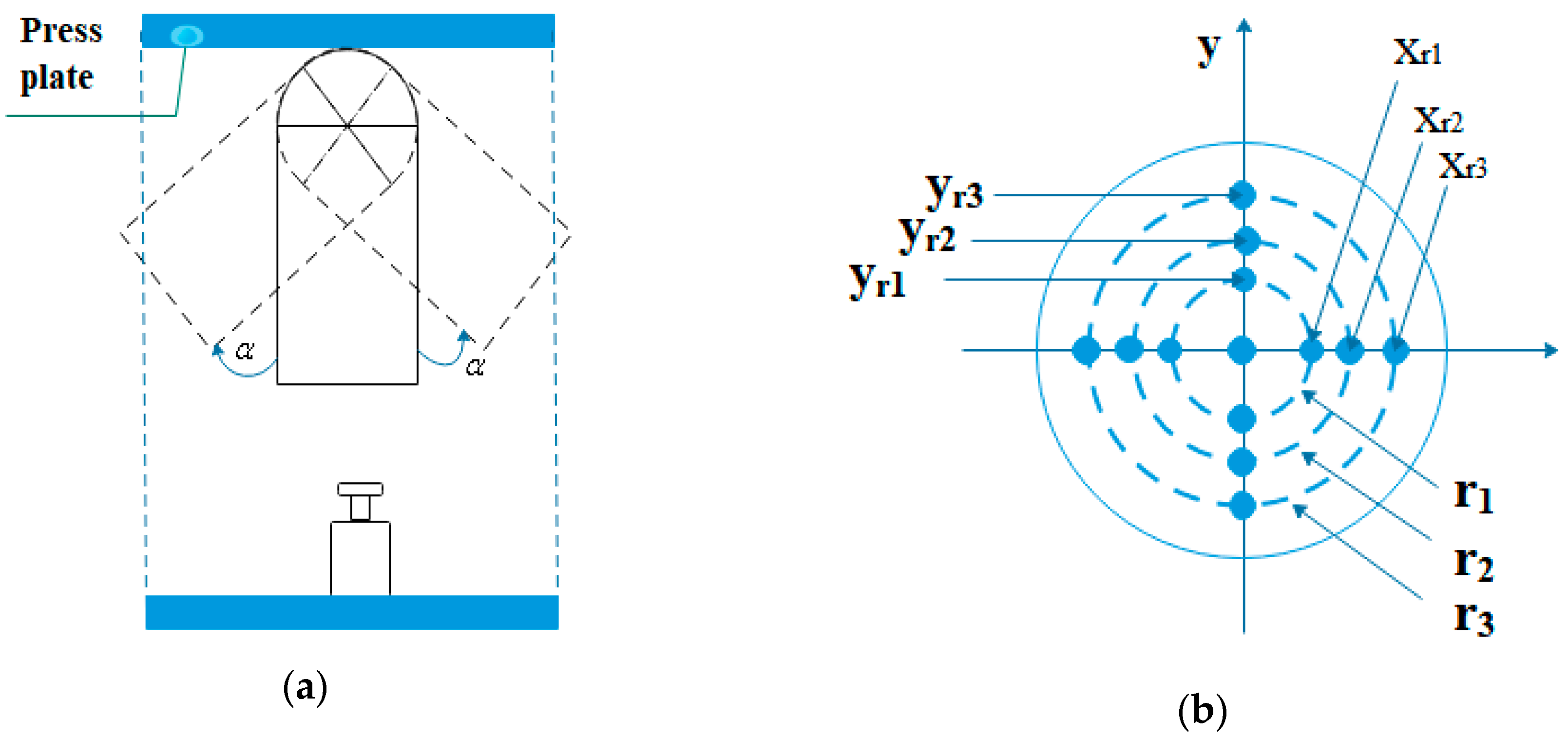
HC9000 was selected as a flexible material for the foot by calibrating the force of different materials. In order to analyze the sense of the force of the foot-end structure in different directions, an omnidirectional force calibration experiment was designed. The end of the foot was fixed to the digital display. Based on observations while the robot walks, the variation range of the angle between the foot end and the z-axis direction was determined to be 0–45 degrees. During the experiment, the x–y direction was changed by 15 degrees. As shown in Figure 7b, r1 indicates that the foot tip was 15° from the z-axis, r2 indicates that the foot tip was 30 degrees from the z-axis, and r3 indicates that the foot tip was 45 degrees from the z-axis. In the x-axis direction, since the foot tips were symmetric, take three points r1, r2, and r3 on the x-axis as xr1, xr2, and xr3, and take three points r1, r2, and r3 on the y-axis as yr1, yr2, and yr3. During the experiment, voltage values of three points and their symmetrical points were measured, and the average values were assigned to points xr1, xr2, xr3 and yr1, yr2, yr3, respectively. The mass of weights was increased in different directions in turn, while the other parameters remained unchanged, and only the force direction of the foot was changed; the change of the voltage value of the FSS pressure sensor was recorded.
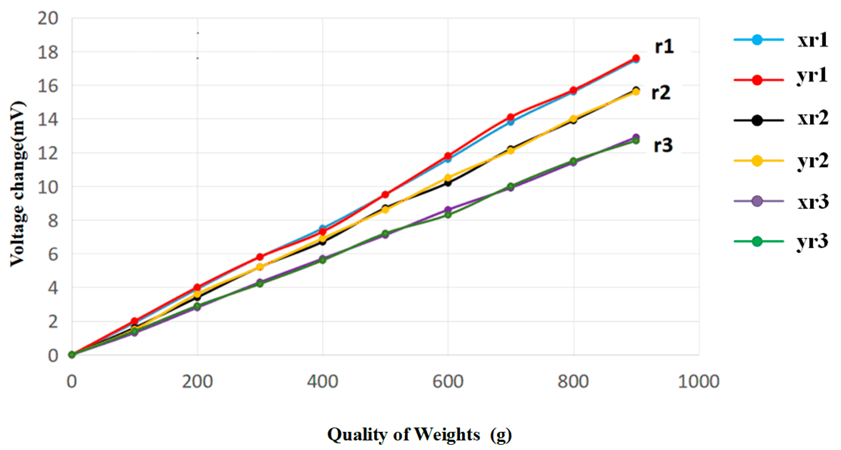
The results obtained from the experiment are shown in Figure 8, where r1, r2, and r3 represent the different angular positions of the foot tip. It can be seen from the figure that on r1, r2, and r3, the stresses on the calibration stress points on x and y were basically the same. At different points of the r1 position, xr1 and yr1 exhibited the same voltage change trend as the weight quality increased, and the error was small, as shown by the red and blue curves in the figure. It can be said that the force of the foot tip was almost the same at any position of the r1 circle. At the r2 and r3 positions, the same change could also be seen. The foot mechanism designed in this paper had uniformity in the perception of the foot-end force. At the same time, it can be seen that under the same external force, the voltage variations of r1, r2, and r3 were also different. The amount of change in voltage was related to the position of the force. The closer to the r1 position at the center of the tip of the foot, the greater the amount of change in the output voltage, and the further away from the center of the foot, the smaller the amount of voltage change. This was because when the weight was applied, the force generated was applied to different positions, and the force angle of the foot tip was also different.
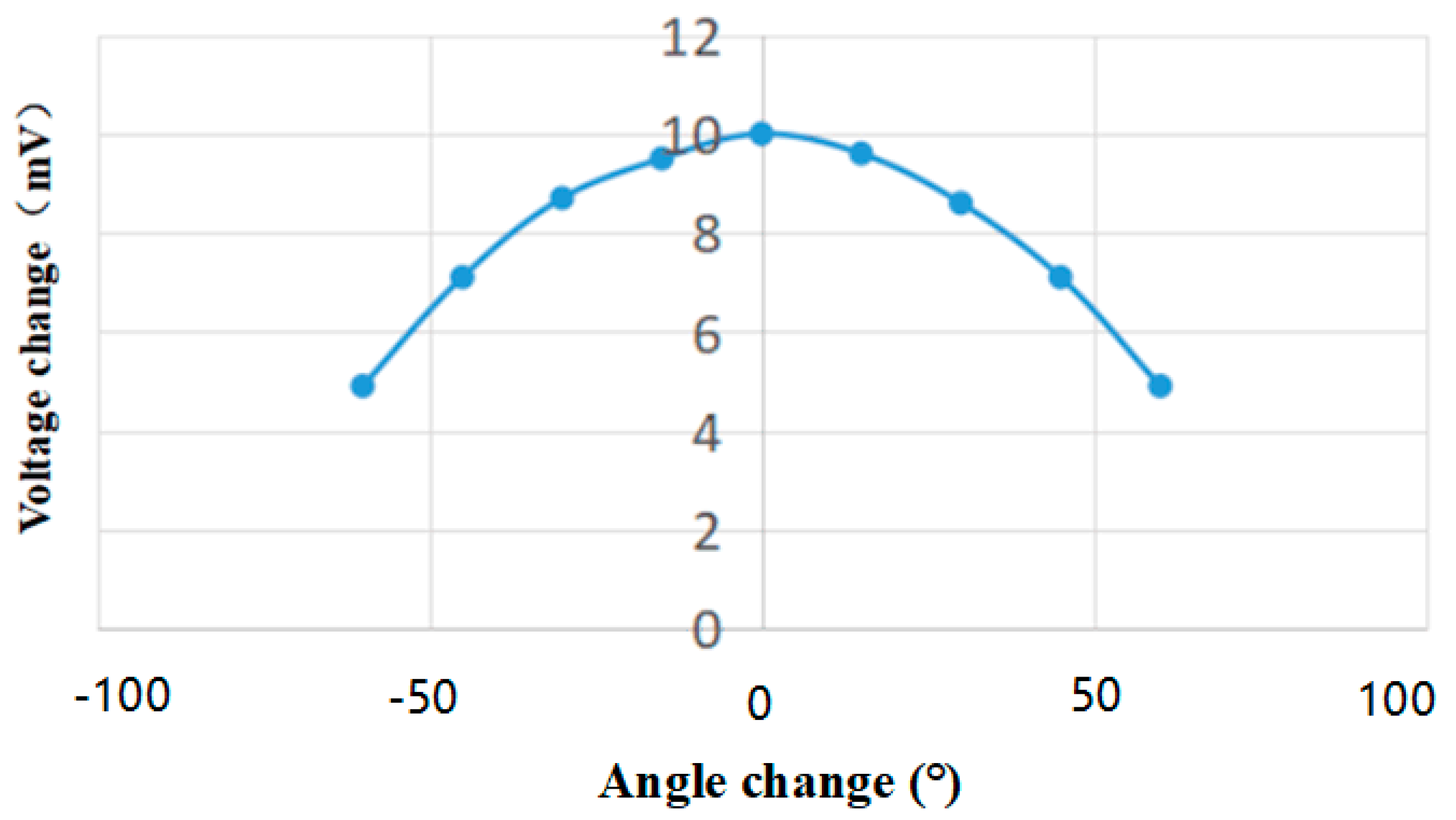
In order to discuss the relationship between the amount of change in the FSS voltage of the foot tip force sensor and the force angle, the same force was applied to the foot tip, the weight was selected to be 500 g, and only the force angle was changed. The force point was selected on the x-axis, and angle values that changed in the negative direction of x were recorded as negative, and angle values that changed in the positive direction of x were recorded as positive; when the foot was perpendicular to the plate, it was recorded as 0°. The amount of voltage change was measured, the average value of three measurements was calculated, and the recorded results are shown in Table 2. The force angle–voltage curve is shown in Figure 9.
As can be seen from the above figure, the amount of voltage change became a symmetrical relationship with the change of the angle value, and the force generated by the weight was F:
Combining the obtained data with Equation (24), the following can be obtained:
The experimentally measured result data (27) and the theoretical calculation formula (22) were basically consistent with the theoretical results. It can be seen that the data measured by the foot FSS pressure sensor were relatively accurate. However, due to its flexibility, the stiffness coefficient of the foot flexible material was very small, and it could be deformed by applying a small force. In the process of stress, it can be regarded as amplifying the force point of the push–pull rod. When it was in contact with the pressure plate, the force-receiving area of the push–pull rod was increased, so the flexible deformation also brought a certain error influence.
In order to study the error caused by the flexible deformation of the foot on the experimental results, the obtained experimental data were straight-line fitted by MATLAB using the least squares method:
- When r1 was deflected by 15 degrees, the fitted straight line was
- When r2 was deflected by 30 degrees, the fitted straight line was
- When r3 was deflected by 45 degrees, the fitted straight line was
The obtained fitting curve was compared with the force applied by the weight to verify the accuracy of the fitting curve. In combination with the actual situation, the multi-legged robot used in this paper usually did not exceed 5 N when the foot was under no load. When the applied force was 5 N, the accuracy of the measurement of the foot tip could reach 4%, that is, the perception of the voltage at the foot end was of 0.1 mV changes. It can be seen from Equation (22) that the relative force perception was less than 0.1 N. Therefore, the flexible foot designed in this paper can effectively reduce the impact force, cause the force to be even and reliable, accurately reflect the change of the foot-end force, and meet the needs of use in the robot.
5. Prototype Experiments and Results Analysis
5.1. Robot Static Attitude Test
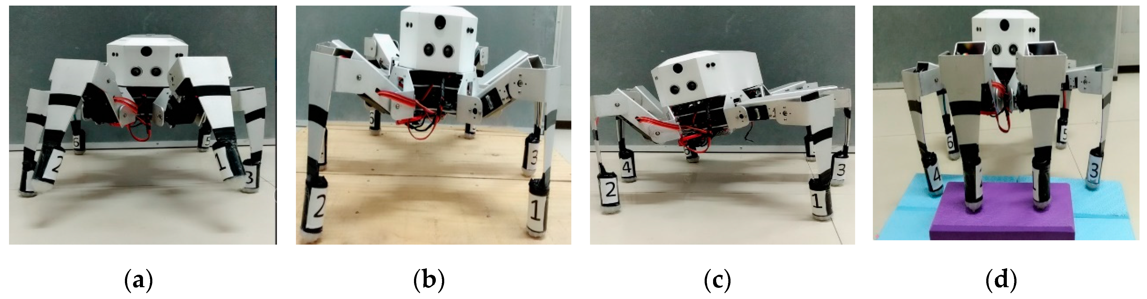
Appropriate prototype is selected for experiment, and parameters of robot prototype are shown in Table 3. In the prototype experiments, this paper adjusted the different postures of the robot on the same ground environment and observed the contact between the foot end of the robot and the ground. As shown in Figure 10, the robot stood in different postures, which kept the foot end in surface contact with the ground, ensuring that the robot was stable under static posture.
In order to verify the accuracy and reliability of the foot-to-force perception, the following experiment was designed.
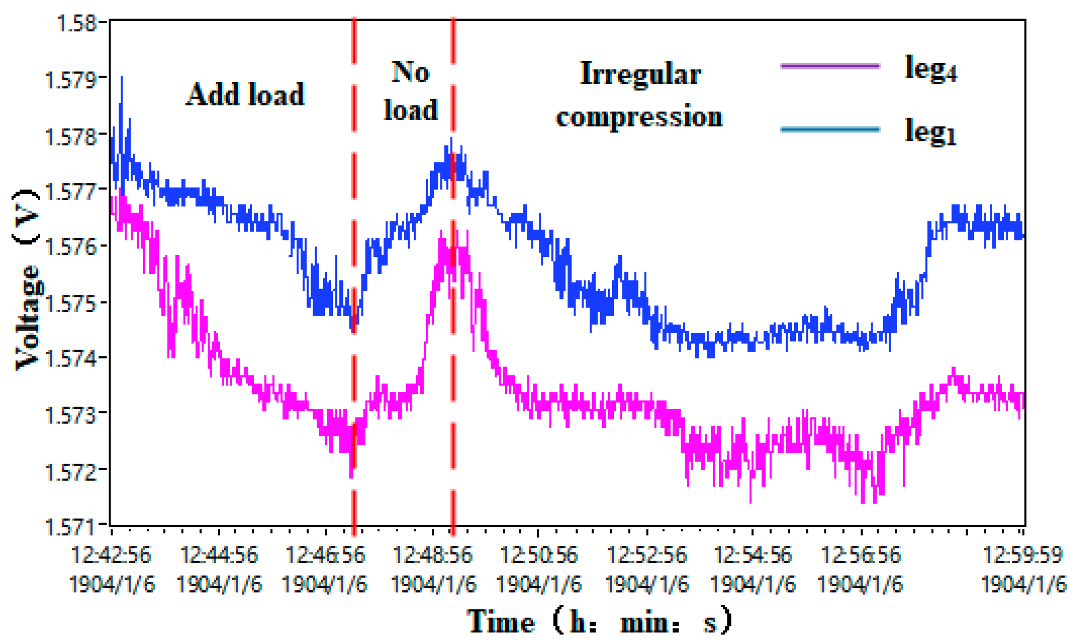
The robot was placed as shown in Figure 10. The legs on the right side of the figure are leg1, leg3, and leg5 from front to back; the legs on the left side of the figure are leg2, leg4, and leg6 from front to back. In the four-legged state (i.e., leg1−leg4 as the supporting legs), since leg3 and leg4 are in the center of the robot and need to bear the weight of leg5 and leg6, leg3 and leg4 are theoretically subjected to more force than leg1 and leg2. Since the perception of the foot force was presented by the voltage output of the sensor, the difference of the force at the foot end was small. In order to make the experimental results more obvious, the DC stabilized power supply was used to supply 5 V, and the acquisition card was adjusted in a high-speed manner. The measurement accuracy was adjusted to 6, that is, we kept six digits after the decimal point, and the sampling speed was 34,723.4 sps. The FSS voltage curves of leg 1 and leg4 were recorded, the load was added at the centroid position of the robot, and the centroid position of the robot was pressed irregularly. The voltage curve was recorded as shown in Figure 11.
As can be seen from Figure 11, whether a load, no load, or irregular pressure was applied, the voltage value of leg4 was always slightly lower than the voltage value of leg1, that is, the force of leg4 was always slightly larger than the force of leg1, which was consistent with the actual force of the foot end. Thus, the force situation was consistent.
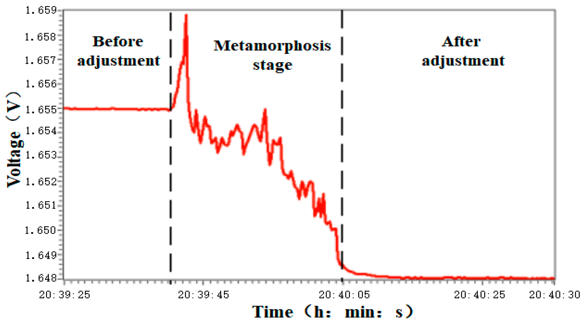
In the hexapod support state, we adjust the position of the center of gravity of the robot to shift it toward the direction of leg4, as shown in Figure 7b. The force of leg4 increases with the shift of the center of gravity. As the center of gravity adjustment ends, the foot−end voltage returns to a stable state, which was in line with the actual force of the robot. At the beginning of the robot’s initial adjustment, the robot suddenly starts moving from a standstill and was constantly adjusted during this process, causing the foot voltage to be unstable.
The experimental results in Figure 12 show that the robot’s foot was relatively accurate in the magnitude of the force, and the force magnitude correctly reflected the trend of the robot’s attitude change. It satisfied the requirements of the robot in the static state for accuracy and reliability of the foot end.
5.2. Omnidirectional Force Calibration
5.2.1. Foot-Tip Force Perception Experiment
The robot walking experiment was designed. The data acquisition card used in the range of −5 V to +5 V had a minimum resolution voltage of 0.152 mV. The robot’s single leg movement time was set to 8 s, the acquisition accuracy was 0.152 mV, the robot’s movement mode adopted a triangular gait, and the foot tip was in vertical contact with the ground. The voltage change at the foot tip during the recording movement is shown in Figure 13.
It can be seen from the figure that when the robot moved, the voltage curve of the foot tip showed obvious periodicity, the law of voltage change was consistent with the actual situation, and the voltage change was stable. For the experimental data processing, the resultant force of the three-legged support was 18.45 N, which was almost the same as the robot’s own gravity 19.04 N, and the error was controlled at about 3%, which realized the real-time measurement of the contact force under the motion state.
5.2.2. Comparison Test of Impact Resistance
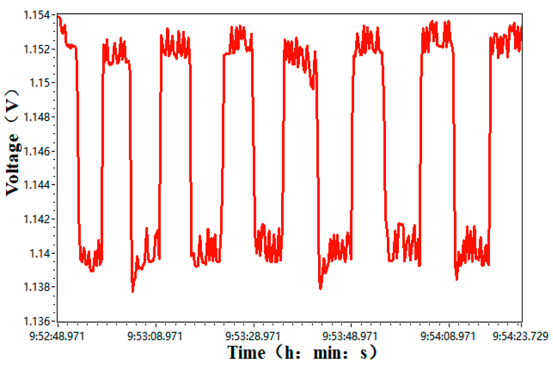
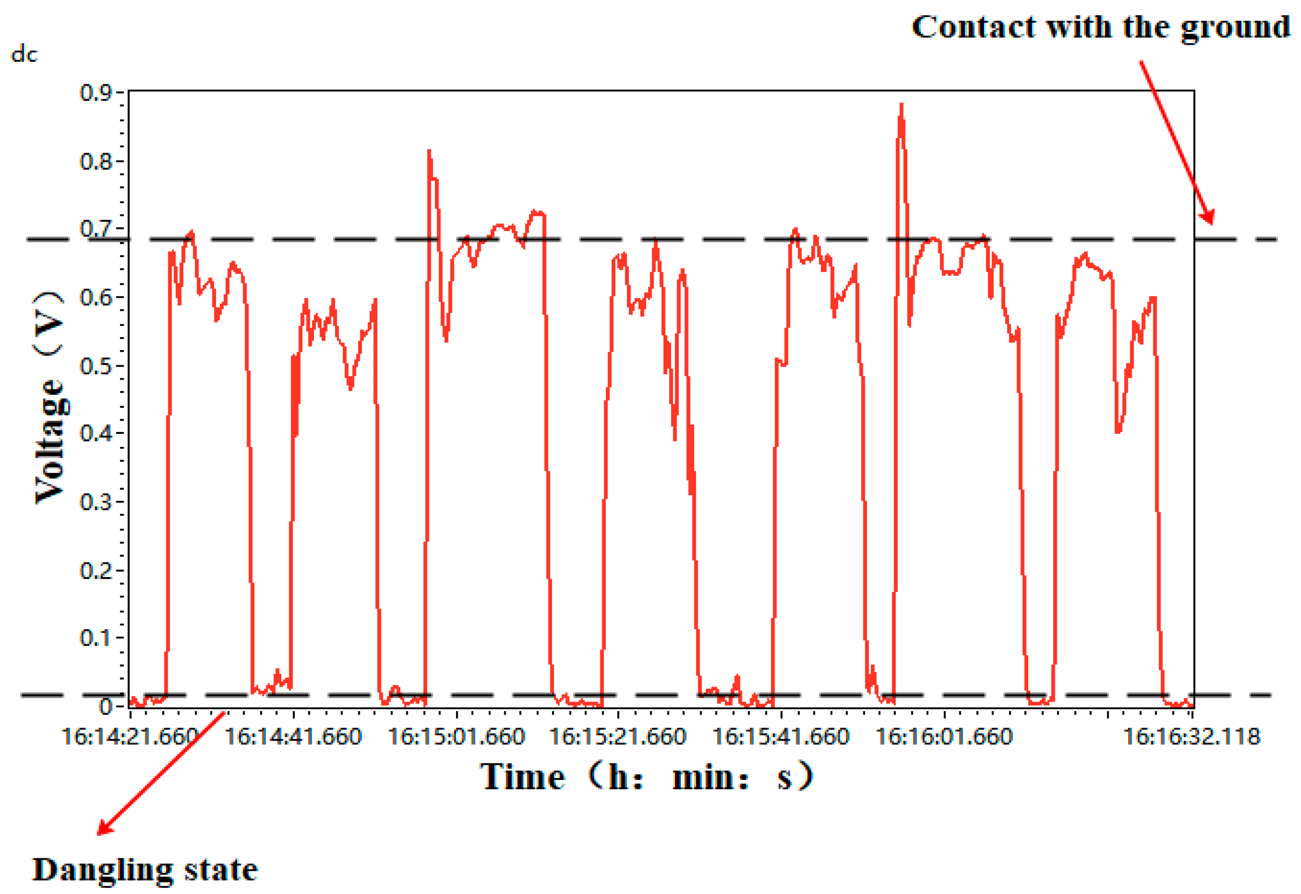
In order to compare the cushioning effect of the flexible mechanism, a patch RFP pressure sensor was added to the rigid foot, and an experiment was designed to study the state of the foot tip when the robot fell. When the robot was standing, the center of mass was the same height and the same posture as the ground. The time on the ground after landing was the same. When the robot fell from the same height, the raw data of the foot tip voltage of the flexible foot robot and the rigid foot robot were recorded, as shown in Figure 14, respectively. The changes of the foot voltage of the two robots were then calculated. Under the same conditions, the rigid foot robot and the robot designed in this paper fell at the same height at the same time.
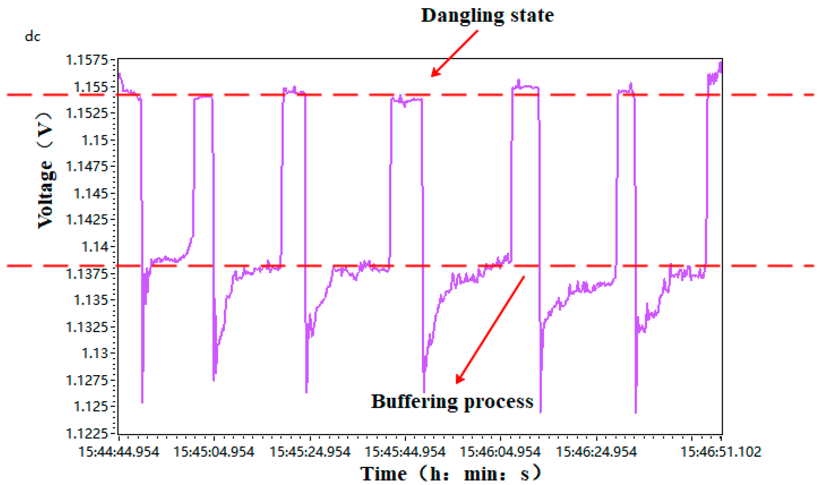
Comparing Figure 14 and Figure 15, it can be seen that the robot with the flexible foot reached the maximum force value at the moment of landing, and the foot experienced a buffer shortly after landing and recovered to a relatively stable voltage value through the foot mechanism buffer. The vibration generated by the steering gear was small. The voltage value vibrated in the range of one tenth of a millivolt after reaching a steady state. Therefore, the cushioning effect of the foot end was better when striking the ground instantly.
5.2.3. Influence and Evaluation of Flexible Foot on Exercise Effect
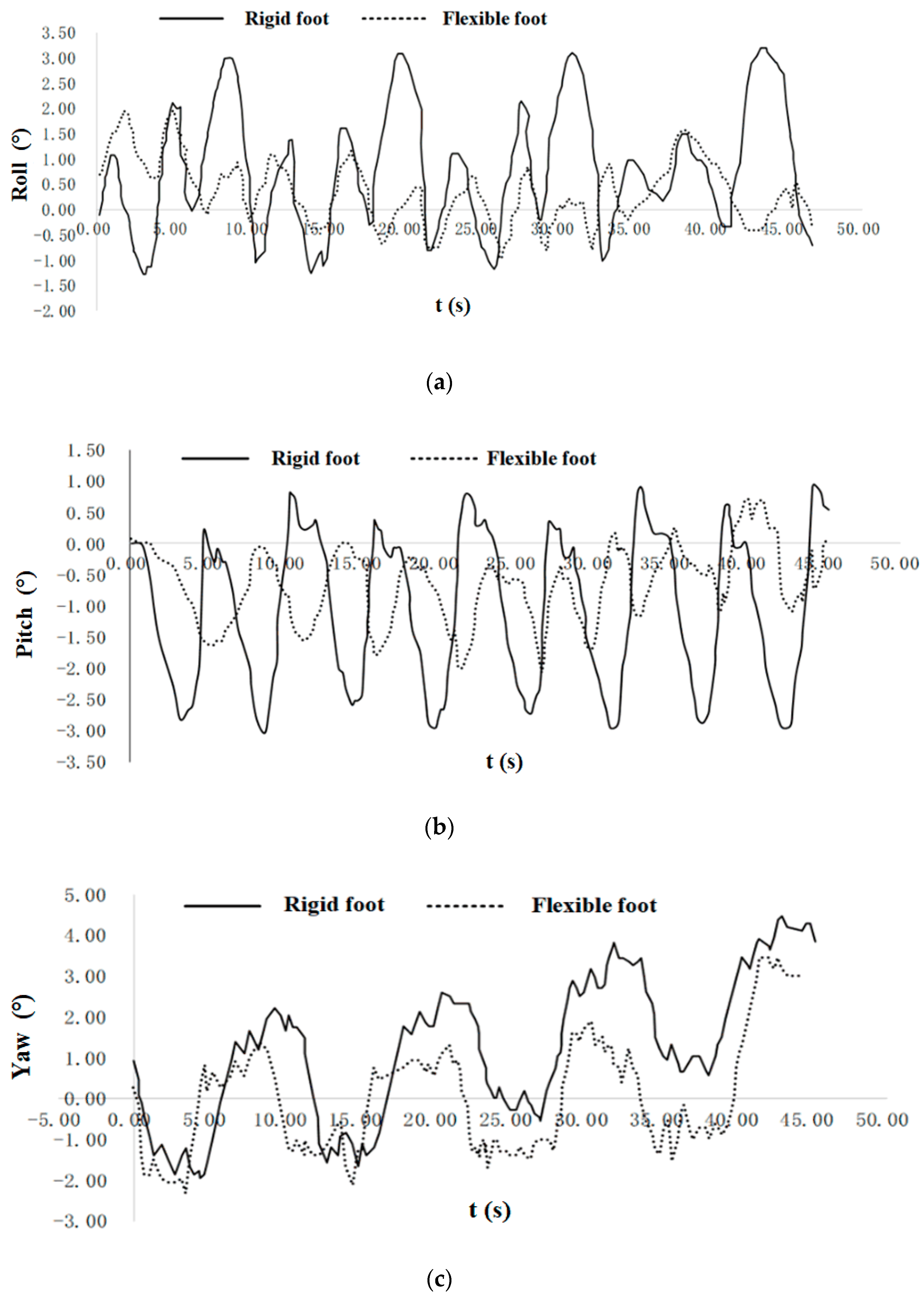
The performance of the same robot was compared when walking with rigid feet and walking with flexible feet. The experimental data curve of the recorded attitude angle curve is shown in Figure 16.
As can be seen from Figure 16, when the robot walked with a rigid foot and a flexible foot, the trend of the attitude angle was about the same. When walking with a flexible foot, the amplitude of the attitude angle was significantly smaller than the amplitude when walking with a rigid foot. After statistical calculation, the minimum peak values of deflection angle, pitch angle, and roll angle of the flexible foot were 37.4%, 29.8%, and 7.8% less than those of the rigid foot, respectively. The results show that the trunk variation of the robot with the flexible foot was significantly smaller than that of the robot with the rigid foot, which was beneficial for the stability of the robot motion.
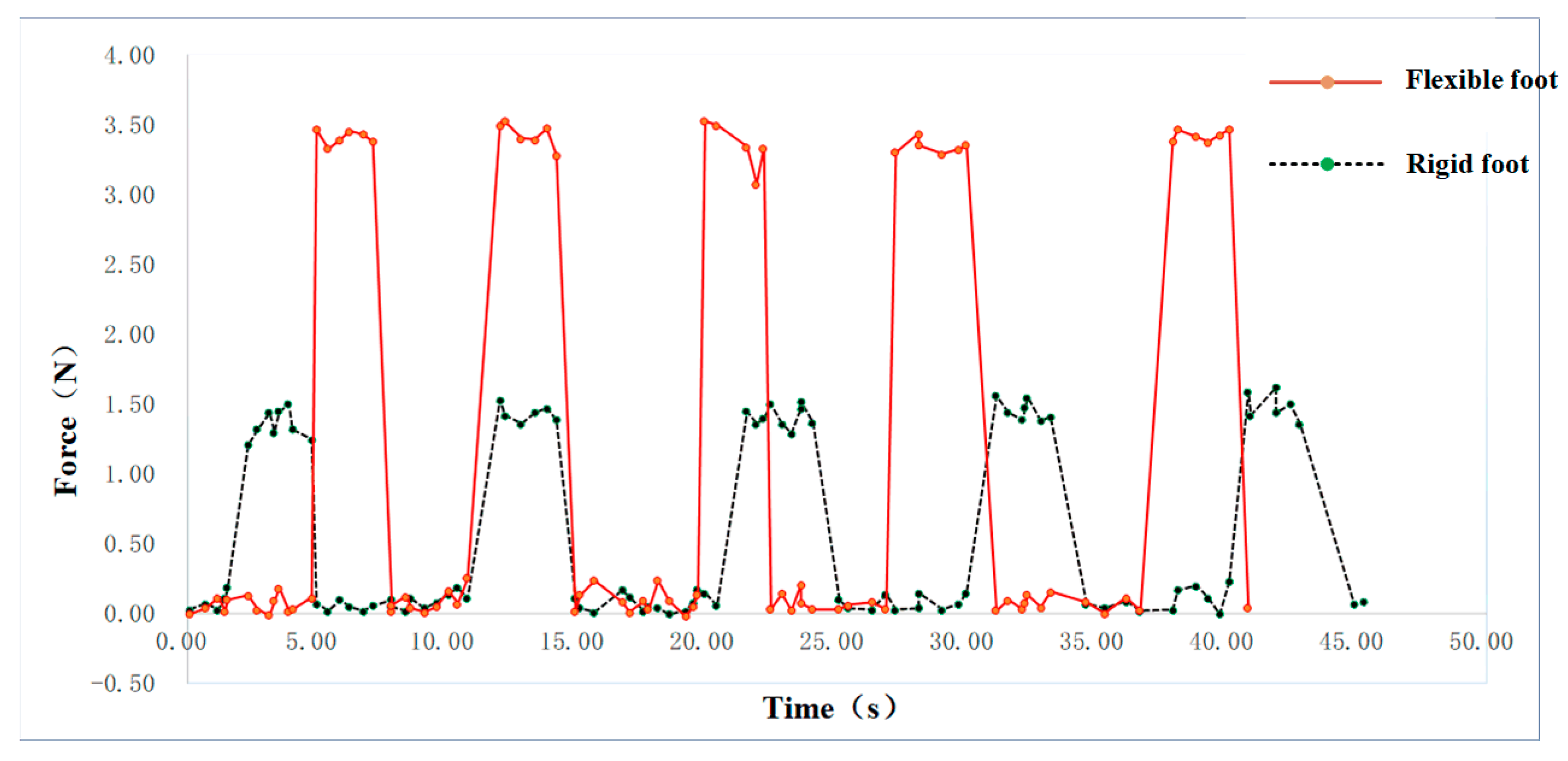
Experiments were designed to study the foot-tip state of the robot walking in a tripod gait. The voltage values of the rigid foot and flexible foot were recorded separately. According to the calibration results in Section 3, the voltage values were converted into foot force. Two decimal numbers were reserved for data processing, as shown in Figure 17.
It can be seen clearly from the graph that the peak force on the foot tip of the robot with the flexible foot was obviously smaller than that of the rigid foot. The average peak pressure of the rigid foot was about 3.47 N, whereas that of the flexible foot was 1.39 N, which was 59% less than that of the rigid foot. The experimental results show that the flexible foot designed in this paper had a very significant effect in cushioning ground impact.
Through different simulation experiments, this section has clearly concluded that when the robot was in motion, the error between the acquired value of the foot tip force and the actual value reached 3.1%. Using the flexible foot, the peak value of the foot tip pressure was reduced by 59% and the maximum smoothness was increased by 37.4% compared with the rigid contact, indicating that the flexible foot structure improved the stability of the robot’s motion process.
5.2.4. Walking Experiments on Different Ground Surfaces
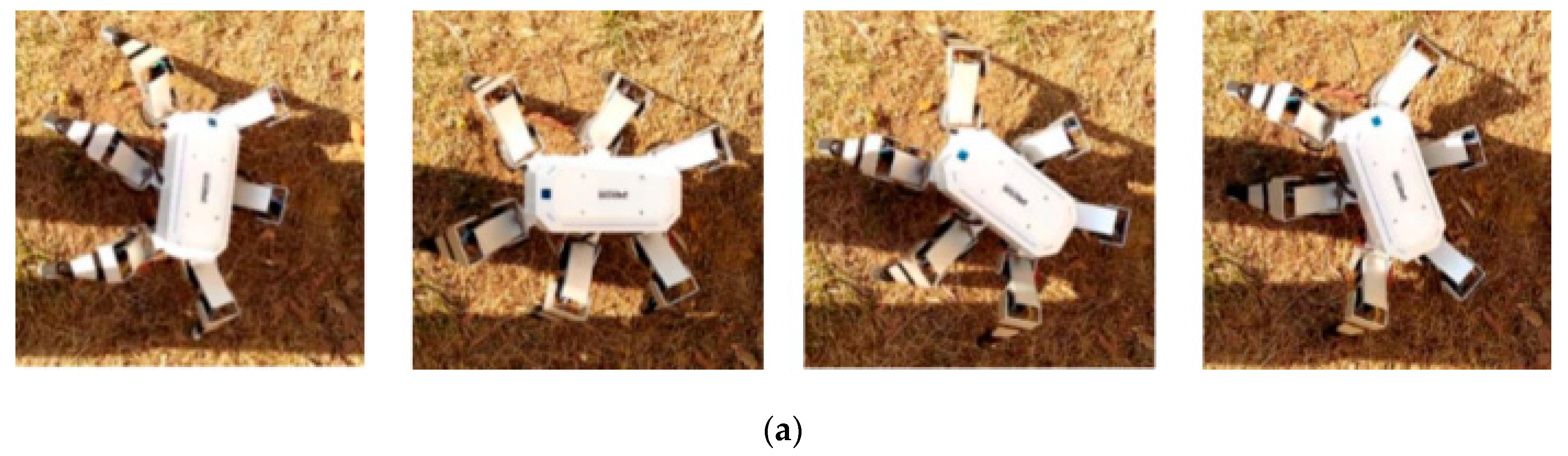
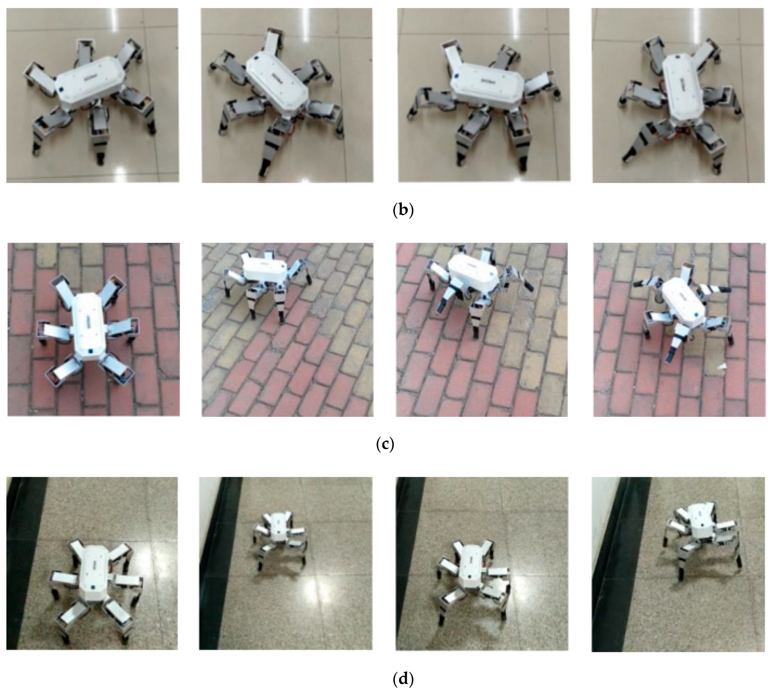
The situations of the robot walking on grass, tile floor, stone brick road floor, and marble floor were recorded separately. As shown in Figure 18, the stability, omnidirectional motion ability, and ground adaptability of the robot in four road environments were verified.
Through the preliminary walking experiment of the flexible foot robot prototype, the robot maintained stable walking on the road surface, no obvious slip on the tile and marble pavement, and the robot moved smoothly and stably on the grassland and stone pavement. The foot structure met the requirements of the robot for stable walking.
6. Conclusions
To overcome the shortcomings of low motion efficiency, large impact, and poor terrain adaptability found in previous robot foot designs, a two-degrees-of-freedom flexible foot structure was proposed and designed in this study. The effects of flexible materials, flexible parameters, and structural forms on the performance of the foot have been discussed. Through simulation and experimentation, parameter analysis and mechanical calibration of the foot were completed, and motion experiments of the flexible robot foot were designed. The results of simulation and experimentation show that the flexible foot structure had uniform and reliable force, which improved the stability of the robot motion process, reduced the vibration, provided the robot with good topographic adaptability, and achieved omnidirectional locomotion of the robot.
Future research will investigate the feasibility of other flexible materials and install multiple sensors at the foot tip in order to achieve multi-dimensional force measurement at the foot tips. Moreover, in the proposed foot structure, the flexible materials and foot tip are connected by silicone gel casting, and the whole foot and the robot are connected by screws; hence, the structure was not quite reliable. Improvements will be made to the rigidity of the connections to make the robot system more stable. At present, some work has been done on the impact of flexible materials on the robot’s posture and stability. In the future, the influences of the flexible foot on the attitude and motion of the robot will be analyzed in detail. Since a spring was adopted at the foot end to absorb the impact force, the vibration phenomenon became nontrivial. In the future, the issue of vibration absorption will be studied by implementing a control algorithm to reduce the impact of vibrations on stability.
Author Contributions
Conceptualization, L.Z. and X.L.; Methodology, L.Z., X.L., Z.G.; Software, L.Z. and X.L.; Validation, P.R., Z.G. and A.L.; Formal analysis, Z.G. and A.L.; Investigation, P.R., Z.G. and A.L.; Resources, L.Z. and X.L.; Data curation, X.L., Z.G. and A.L.; Writing—Original draft preparation, L.Z., X.L., Z.G. and A.L.; Writing—Review and Editing, L.Z., X.L., Z.G. and A.L.; Supervision, L.Z. and P.R.; Project administration, L.Z. and P.R.; Funding acquisition, L.Z. and P.R.
Funding
This research was supported by The National Natural Science Foundation of China (60704023, 40976059).
Conflicts of Interest
The authors declare no conflict of interest.
References
- Billah, M.M.; Ahmed, M.; Farhana, S. Walking hexapod robot in disaster recovery: Developing algorithm for terrain negotiation and navigation. Proc. World Acad. Sci. Eng. Technol. 2008, 42, 328–333. [Google Scholar]
- Huang, Q.J.; Nonami, K. Humanitarian mine detecting six–legged walking robot and hybrid neuro walking control with position/force control. Mechatronics 2003, 13, 773–790. [Google Scholar] [CrossRef]
- Shi, Y.; Ding, G.; Zhang, M.; Zhang, X. Foot end trajectory with small oscillation generation method of the adjustable stiffness active flexible joint robot. In Proceedings of the 2016 IEEE International Conference on Robotics and Biomimetics (ROBIO), Qingdao, China, 3–7 December 2016; pp. 455–460. [Google Scholar]
- Low, K.H.; Yang, A. Design and foot contact of a leg mechanism with a flexible gear system. In Proceedings of the 2003 IEEE International Conference on Robotics and Automation (Cat. No. 03CH37422), Taipei, Taiwan, 14–19 September 2003; Volume 1, pp. 324–329. [Google Scholar]
- Fan Jihua, Z.G.; Hong, C. Dynamic analysis and simulation of robot considering joint flexibility. Comput. Simul. 2017, 8, 331–336. [Google Scholar]
- Wen, L.; Wang, H. Software robot research outlook: Structure, drive and control. Robot 2018, 40, 577. [Google Scholar]
- Zhang, L.; Liu, X.; Guo, X. Development of Hexapod Robot with one passive joint on foot. In Proceedings of the 2017 IEEE International Conference on Robotics and Biomimetics (ROBIO), Macau, China, 5–8 December 2017; pp. 1082–1087. [Google Scholar]
- Yanlei, S.; Minglu, Z.; Xiaojun, Z. Design and analysis of four-legged mechanical legs with flexible joints. J. Huazhong Univ. Sci. Technol. (Nat. Sci. Ed.) 2017, 40, 3. [Google Scholar]
- Bingbing, H.; Guoqing, J. Design and manufacture of a multi-drive software robot that resembles the tiger larvae. Robot 2018, 40, 626–633. [Google Scholar]
- Howe, R.D. Tactile sensing and control of robotic manipulation. Adv. Robot. 1993, 8, 245–261. [Google Scholar] [CrossRef]
- Haoyu, R.; Qimin, L.; Jianxin, J. Design and analysis of the leg structure of a new type of elastic foot robot. Mech. Sci. Technol. 2018, 37, 372–379. [Google Scholar]
- Galloway, K.C.; Clark, J.E.; Koditschek, D.E. Variable stiffness legs for robust, efficient, and stable dynamic running. J. Mech. Robot. 2013, 5, 011009. [Google Scholar] [CrossRef]
- Hamill, S.; Peele, B.; Ferenz, P.; Westwater, M.; Shepherd, R.F.; Kress-Gazit, H. Gait Synthesis for Modular Soft Robots. In Proceedings of the International Symposium on Experimental Robotics, Tokyo, Japan, 3–6 October 2016; pp. 669–678. [Google Scholar]
- Xiang, G. Research on State Recognition and Control of Software Crawling Robot; Harbin Institute of Technology: Harbin, China, 2018. [Google Scholar]
- Yibin, L.; Bin, L.; Xuewen, R.; Jian, M. Structural design and gait planning for hydraulically driven four-legged bionic robots. J. Shandong Univ. (Eng. Ed.) 2011, 41, 32–36. [Google Scholar]
- Chai Hui, M.J.; Xuewen, R. Design and implementation of high–performance hydraulically driven quadruped robot SCalf. Robot 2014, 36, 385–391. [Google Scholar]
- Riese, S.; Seyfarth, A. Stance leg control: Variation of leg parameters supports stable hopping. Bioinspir. Biomim. 2011, 7, 016006. [Google Scholar] [CrossRef] [PubMed]
- Wang, D.; Guo, J.; Sun, C.; Xu, M.; Zhang, Y. A flexible concept for designing multiaxis force/torque sensorsusing force closure theorem. IEEE Trans. Instrum. Meas. 2013, 62, 1951–1959. [Google Scholar] [CrossRef]
- Wang, X.; Li, M.; Wang, P.; Sun, L. Running and turning control of a quadruped robot with compliant legs in bounding gait. In Proceedings of the 2011 IEEE International Conference on Robotics and Automation, Shanghai, China, 9–13 May 2011; pp. 511–518. [Google Scholar]
- Zhang, X.; Ye, T.; Zhu, J.; She, H.; Xin, L.; Sun, W. A novel self-adaptive bionic robot hand with flexible fingers. In Proceedings of the IEEE International Conference on Robotics & Biomimetics, Macau, China, 5–8 December 2017. [Google Scholar]
- Liu, Z.; Song, L.-B.; Li, Y.; Pan, B.-Z. Rigid-Flexible Coupling Simulation and Vibration Analysis of Flexible Robot. In Proceedings of the International Conference on Mechanical, Automotive and Materials Engineering, Guangzhou, China, 1–3 August 2017. [Google Scholar]
- Kand, M.S.T.; Sadeghian, R.; Masouleh, M.T. Design, analysis and construction of a novel flexible rover robot. In Proceedings of the RSI International Conference on Robotics & Mechatronics, Tehran, Iran, 7–9 October 2015. [Google Scholar]
- Sun, W.; Su, S.F.; Xia, J.; Nguyen, V.T. Adaptive Fuzzy Tracking Control of Flexible-Joint Robots with Full-State Constraints. IEEE Trans. Syst. Man Cybern. Syst. 2018. [Google Scholar] [CrossRef]
- Ling, S.; Wang, H.; Liu, P.X. Adaptive Fuzzy Tracking Control of Flexible–Joint Robots Based on Command Filtering. IEEE Trans. Ind. Electron. 2019. [Google Scholar] [CrossRef]
- Ding, K.; Song, G.; Qiao, G. Multi-footed bionic robot foot mechanism design with 3D force perception. Robot 2016, 38, 75–81. [Google Scholar]
- Castaño, F.; Toro, R.M.D.; Haber, R.E.; Beruvides, G. Conductance sensing for monitoring micromechanical machining of conductive materials. Sens. Actuators A Phys. 2015, 232, 163–171. [Google Scholar] [CrossRef]
- Beruvides, G.; Quiza, R.; del Toro, R.; Castaño, F.; Haber, R.E. Correlation of the holes quality with the force signals in a microdrilling process of a sintered tungsten-copper alloy. Int. J. Precis. Eng. Manuf. 2014, 15, 1801–1808. [Google Scholar] [CrossRef]
Figure 1.
Simplified model of foot mechanism: (a) foot tip mechanical structure; (b) foot tip sectional view.
Figure 1.
Simplified model of foot mechanism: (a) foot tip mechanical structure; (b) foot tip sectional view.

Figure 2.
Spring structure.

Figure 3.
Mechanical analysis model of foot tip: (a) device model; (b) force model.

Figure 4.
The platform of the foot-end calibration experiment.

Figure 5.
Calibration schematic diagram of foot mechanism.

Figure 6.
Comparisons of foot-tip flexible materials.

Figure 7.
Experiments of full-direction force acting on the foot tip: (a) change of foot direction; (b) calibration of stress point position.
Figure 7.
Experiments of full-direction force acting on the foot tip: (a) change of foot direction; (b) calibration of stress point position.

Figure 8.
All-directional calibration result curves of foot tip.

Figure 9.
The relationship between the voltage and angle.

Figure 10.
Different postures of robot. (a) Quadruped support; (b) left shift of center of gravity; (c) hexapod support on slopes; (d) upstairs.
Figure 10.
Different postures of robot. (a) Quadruped support; (b) left shift of center of gravity; (c) hexapod support on slopes; (d) upstairs.

Figure 11.
Voltage variation curve of leg1 and leg4 in quadruped support stage.

Figure 12.
Leg4 foot-tip voltage variation with center of gravity shifting to the left.

Figure 13.
Foot voltage in motion.

Figure 14.
Voltage curve of rigid-footed robot when it crashed.

Figure 15.
Voltage curve of flexible-footed robot when it crashed.

Figure 16.
Attitude angle curve of robot walking. (a) change of roll angle; (b) change of pitch angle; (c) change of yaw angle.
Figure 16.
Attitude angle curve of robot walking. (a) change of roll angle; (b) change of pitch angle; (c) change of yaw angle.

Figure 17.
Pressure curves for two kinds of foot.

Figure 18.
Robot walking on different ground types. (a) Turning on grassland; (b) turning on tile pavement; (c) turning on stone pavement; (d) walking in a straight line on marble pavement.
Figure 18.
Robot walking on different ground types. (a) Turning on grassland; (b) turning on tile pavement; (c) turning on stone pavement; (d) walking in a straight line on marble pavement.


Table 1.
Spring parameter table.
| Parameter | Symbol |
|---|---|
| Spring wire diameter | d |
| Outer diameter | D |
| inside diameter | D2 |
| Free height | H0 |
| Pitch | t |
| Spiral angle |
Table 2.
Spring parameter table.
| Parameters | Variation | ||||||||
|---|---|---|---|---|---|---|---|---|---|
| Angle (°) | −60 | −45 | −30 | −15 | 0 | 15 | 30 | 45 | 60 |
| Voltage change (mV) | 4.8 | 7.0 | 8.5 | 9.7 | 10 | 9.6 | 8.6 | 6.9 | 4.8 |
Table 3.
Robot parameters.
| Structure Parameter | Symbol | Values | Unit |
|---|---|---|---|
| length of coxa | l1 | 75 | mm |
| length of femur | l2 | 105 | mm |
| length of tibia | l3 | 145 | mm |
| angle of talocalcaneal joint | −45–45 | ||
| angle of hip join | −45–90 | ||
| angle of keen join | −120–0 | ||
| quality of coxa | 0.042 | kg | |
| quality of femur | 0.044 | kg | |
| quality of tibia | 0.040 | kg | |
| height of center of gravity | H | 50–140 | mm |
| total mass | G | 2.01 | kg |
© 2019 by the authors. Licensee MDPI, Basel, Switzerland. This article is an open access article distributed under the terms and conditions of the Creative Commons Attribution (CC BY) license (http://creativecommons.org/licenses/by/4.0/).
Share and Cite
MDPI and ACS Style
Zhang, L.; Liu, X.; Ren, P.; Gao, Z.; Li, A. Design and Research of a Flexible Foot for a Multi-Foot Bionic Robot. Appl. Sci. 2019, 9, 3451. https://doi.org/10.3390/app9173451
AMA Style
Zhang L, Liu X, Ren P, Gao Z, Li A. Design and Research of a Flexible Foot for a Multi-Foot Bionic Robot. Applied Sciences. 2019; 9(17):3451. https://doi.org/10.3390/app9173451
Chicago/Turabian StyleZhang, Lei, Xinzhi Liu, Ping Ren, Zenghui Gao, and Ang Li. 2019. "Design and Research of a Flexible Foot for a Multi-Foot Bionic Robot" Applied Sciences 9, no. 17: 3451. https://doi.org/10.3390/app9173451
Note that from the first issue of 2016, this journal uses article numbers instead of page numbers. See further details here.