Fault Detection of Stator Inter-Turn Short-Circuit in PMSM on Stator Current and Vibration Signal


1
School of Automation Engineering, University of Electronic Science and Technology of China, Chengdu 611731, China
2
Institute of Electric Vehicle Driving System and Safety Technology, University of Electronic Science and Technology of China, Chengdu 611731, China
3
Unit 69031 of the people’s liberation army of China, Urumqi 830000, China
*
Author to whom correspondence should be addressed.
Appl. Sci. 2018, 8(9), 1677; https://doi.org/10.3390/app8091677
Submission received: 7 September 2018
/
Revised: 12 September 2018
/
Accepted: 14 September 2018
/
Published: 16 September 2018
(This article belongs to the Special Issue Fault Detection and Diagnosis in Mechatronics Systems)
Abstract
:The stator inter-turn short circuit fault is one of the most common and key faults in permanent magnet synchronous motor (PMSM). This paper introduces a time–frequency method for inter-turn fault detection in stator winding of PMSM using improved wavelet packet transform. Both stator current signal and vibration signal are used for the detection of short circuit faults. Two different experimental data from a three-phase PMSM were processed and analyzed by this time–frequency method in LabVIEW. The feasibility of this approach is shown by the experimental test.
1. Introduction
With the development of technology, Permanent magnet Synchronous Motors (PMSM) have become some of the most important electric machines. In PMSM, the magnetic flux induced in the stator windings is generated by rare-earth magnets located on the rotor [1]. As a result, PMSM has some excellent features, such as high efficiency, high output to volume ratio, high power to weight ratio and low noise emissions [2]. With these advantages, PMSM is widely used in some industrial applications, such as robotic, automotive and electric traction.
However, a motor fault might cause production shutdowns. These shutdowns may lead to wasting production time and raw resources. Therefore, it is necessary to focus on the condition monitoring and fault diagnosis methods. PMSM usual faults include electrical faults, mechanical faults and magnetic faults. Stator inter-turn short-circuit belongs to electrical faults [3], and it is one of the most common motor faults in PMSM.
There are three common fault diagnosis methods: model-based, knowledge-based, and signal-based. The model-based method requires an accurate mathematical model of the motor, while knowledge-based method requires extensive expert experience. Thus, signal-based method is widely used in the field of PMSM fault diagnosis, and the method is fast and does not need any specific model.
Signal-based method detects fault by processing the signals collected from the motors to find the difference between healthy PMSM and faulty PMSM. Current and vibration signals have long been used in motor fault detection [4]. Current signals are the most commonly used, one reason obeing that these signals are not disturbed acoustic signals [5]. Vibration signals are often used in the diagnosis of bearing faults [6]. As for signal processing tools, fast Fourier transform (FFT) is a traditional tool to extract the frequency characteristics of the stator current signal [7]. However, it is sometimes difficult to obtain obvious fault characteristics by only relying on the stator current signal. Besides, due to loss of time information, FFT can only be used to process stationary signal. Therefore, the time–frequency techniques have received more attention, such as short-time Furrier transform (STFT), wavelet transform (WT) and the empirical wavelet transform (EWT) [8].
There have been some studies using signal processing method to diagnose motor faults. Stavrou and Henao found that, when the stator inter-turn short-circuit fault occurs in the motor, an increased fault harmonic occurs in the stator current [9,10]. Sdiri, F. et al. proposed a strategy based on a motor fault model [11]. Using MATLAB/Simulink, the current characteristics in the fault condition were found and the short circuit fault was detected. In [12], the PMSM stator current signal is decomposed by wavelet packet transform, and the signal energy value of each frequency band is calculated. The increase of energy is used as the basis of fault judgment. In [13], by analyzing the harmonic components of the current and voltage of the motor with inter-turn short circuit fault, the FFT transform is used to obtain the characteristics of the space vector spectrum to detect the fault. In [14], wavelet analysis is used to extract the fault characteristics of the induction motor, which is better than the Fourier transform. In [15,16], wavelet analysis is also used in PMSM fault diagnosis. A method based on a variety of signals has been used in the fault diagnosis of induction motors [17]. Some studies [18,19] adopt the method of fusion of stator current, vibration and noise signals, and detect the short circuit fault based on the signal spectrum increment.
In this paper, both stator current signal and vibration signal are used for the detection of short circuit fault. The two parameters are analyzed by the time–frequency method using improved wavelet packet transform. Improved wavelet packet transform can eliminate spectrum aliasing and get accurate fault characteristics. The feasibility of this approach is shown by the experimental test.
2. Materials and Methods
Stator inter-turn short circuit fault is a common fault in PMSM, which is due to the problems in stator winding insulation. If not diagnosed in time, it will spread to more stator turns and even cause other motor faults.
When short circuit occurs in the stator winding of a motor, the harmonic component in the stator current will increase. According to some related research [20], the harmonic components at the following frequencies will increase:
where fs is the frequency of the source and v is a positive integer number, Z is the number of stator slots and p is the number of pole pairs. In PMSM, the most obvious of these harmonic components is the third harmonic component [21,22].
Furthermore, the stator inter-turn short circuit fault and the three-phase asymmetry of the motor windings can bring magnetic field asymmetry, which can in turn create abnormal vibrations. When the motor is running normally, the vibration frequency of the stator should be twice the frequency of the source. However, these abnormal vibrations could cause the vibration signal to have the harmonic components of 4fs and 8fs in addition to the fundamental frequency of 2fs.
As for the signal processing method, wavelet analysis can decompose signals into time and frequency domain, simultaneously [23]. Wavelet analysis offers a windowing technique with variable-sized regions, which is stable in FFT and STFT. Because of this, wavelet analysis has become a commonly used time–frequency analysis method of signal processing. The most basic wavelet transform is calculated as:
where ψ(x) is a wavelet basis function, a is a scaling factor which represents the frequency component of the signal, and b is a translation factor which represents the time position.
In wavelet analysis, wavelet transform can only analyze the low frequency part of the signal, ignoring the high frequency part. However, the wavelet packet transform can further analyze all frequency components. The flow of the fast algorithm for binary wavelet packet analysis is shown in Figure 1.
The fast algorithm for binary wavelet packet decomposition is:
where t = 1, 2, …, , i = 1, 2, …, , and J = log2N. f(t) is a time signal. P(t) is called the wavelet packet coefficient. H stands for wavelet decomposition low frequency filters and G for high frequency.
The fast algorithm for binary wavelet packet reconstruction is:
where j = J − 1, J − 2, …, 0, i = , , …, 1. h stands for wavelet reconstruction low frequency filters and g for high frequency.
However, the above decomposition and reconstruction algorithms are also flawed because the wavelet packet fast algorithm includes three operations: wavelet filter convolution, interlaced sampling and interleaved zero, which could cause frequency confusion. To solve this problem, the improved wavelet packet transform was invented.
To eliminate the frequency aliasing, the improved wavelet packet decomposition and reconstruction algorithms have two operators: C and D.
The formula of operator C is:
The formula of operator D is:
where x(n) is the wavelet packet coefficients of low frequency subbands on scale, Nj is the data length, k = 0, 1, …, Nj−1, and n = 0, 1, …, Nj−1.
The experimental platform structure diagram is shown in Figure 2. It consists of a three-phase permanent magnet synchronous motor, NI Data acquisition card (DAQ card), current sensors and a vibration sensor. The data collected by the sensors were uploaded to a computer with LabVIEW installed by DAQ card for processing and analysis.
The experimental platform can be divided into hardware part and software part.
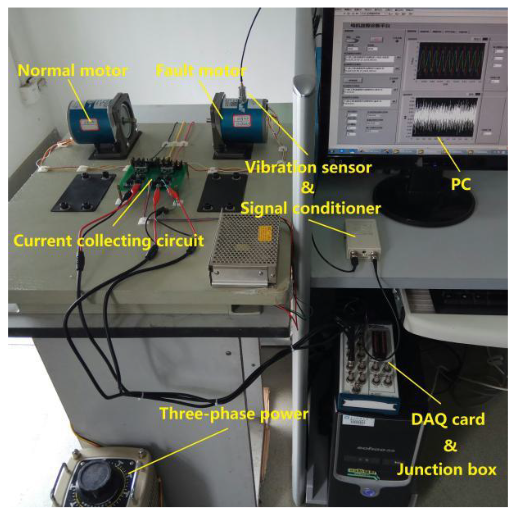
The hardware of the experimental platform for PMSM fault detection is shown in Figure 3.
Two permanent magnet low speed synchronous motors were used in the experiment. One is a normal motor and the other is a motor that is artificially placed with a 15% inter-turn fault in the stator. The motor is shown in Figure 4. This PMSM has 13 poles and 12 stator slots; its rated frequency is 50 Hz; and its rated power is 95 W.
The stator current of these motors was collected by current sensors, which were produced by TAMURA Corporation in Tokyo, Japan in 2018. The measuring range of the sensor is 0–3 A, and the output voltage is 0–4 V. This current sensor can convert the current signals into voltage signals, which are easy for the computer to process.
The vibration signal was collected by piezoelectric accelerometer, whose voltage sensitivity is 100 mV/g, frequency response range is 0.5–6000 Hz and maximum output signal is 6 V. The sensor was attached radially to the housing of the motor. A signal conditioner, YE3832, was used to condition the sensor output and send it to the computer. Both the vibration sentor and the signal conditioner were produced by Wuxi Shiao Technology Co., Ltd in Wuxi, China in 2018.
Data acquisition card was installed in the computer and connected to a junction box, to facilitate the data input from the sensors. Both they were produced by National Instruments (NI) in Austin, Texas, U.S. in 2017.
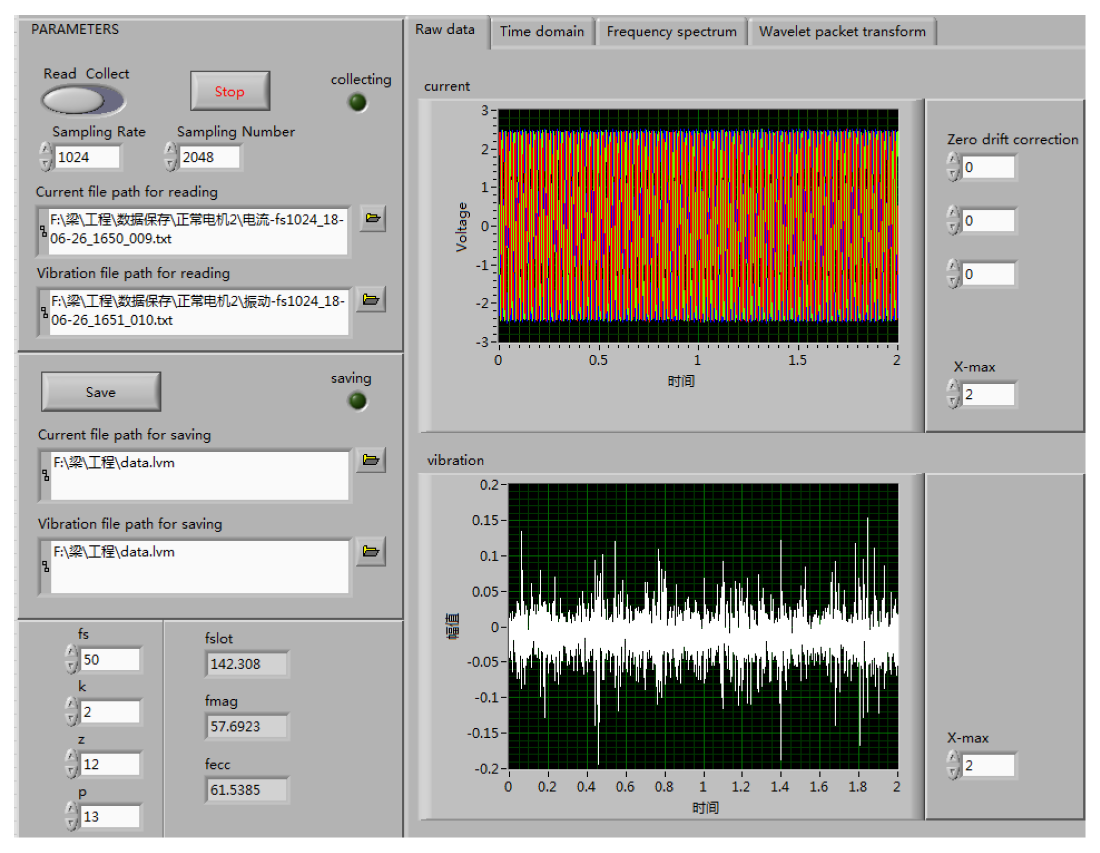
As for the software, LabVIEW 2017 is a program development platform developed by NI in Austin, Texas, U.S. in 2017. It has become a versatile tool with a straightforward block diagram language. In this study, LabVIEW was used to implement signal analysis algorithms, monitor the collected data, and design time–frequency transform program.
The fault detection system built on LabVIEW is shown in Figure 5. Data acquisition channels and sampling parameters are set on the left side of the system, and the waveform and processing results of the signal are displayed on the right side. The results of time domain analysis, frequency domain analysis, and wavelet analysis are all displayed in different modules.
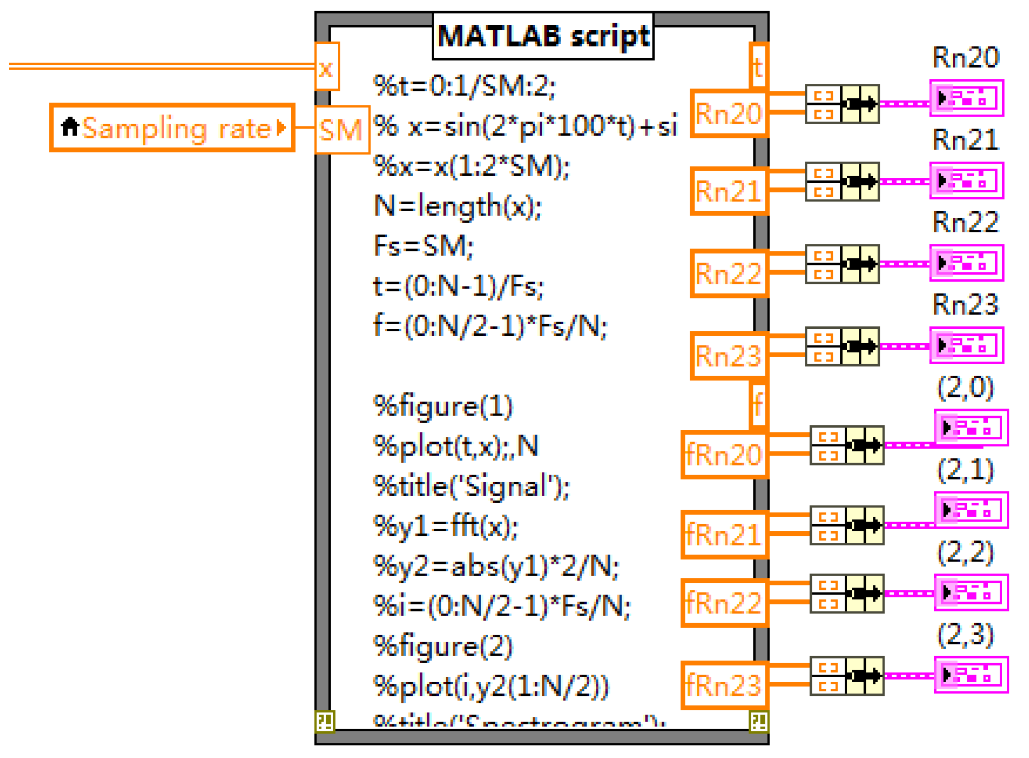
The improved wavelet packet algorithm was imported using the MathScript node in LabVIEW, as shown in Figure 6. The signal is decomposed, reconstructed and transformed by wavelet packet.
3. Results
In the experiment, a stator winding motor with a single phase of 15% inter-turn short circuit fault was compared with the normal motor. Both the current signal and vibration signal were analyzed to extracting the fault features.
3.1. Current Signal
The three-phase stator current waveform of the motor with inter-turn short circuit fault is shown in Figure 7. It can be seen in this diagram that the amplitude of the current in phase A, the phase with short circuit fault, is obviously higher than that in the other two phases.
Then, the signal of fault phase was extracted separately, and the improved wavelet packet algorithm was used to decompose it into four wavelet packet nodes: (2, 0), (2, 1), (2, 2) and (2, 3). The results of reconstructing these wavelet packet nodes are shown in Figure 8.
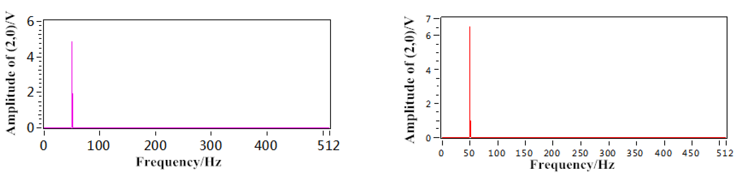
To observe the frequency distribution, the reconstructed nodes were transformed by FFT and compared with the results of normal motor signals. As shown in Figure 9, the changes of the frequency at (2, 0) and (2, 1) are obvious.
It can be seen from (2, 0) that the amplitude of fundamental frequency, in other words, fs = 50 Hz, increases. From (2, 1) it can be seen that the amplitude at the third harmonic frequency, in other words, 3fs = 150 Hz, of the normal motor signal is very small, but the third harmonic component of the fault motor signal increases and even reaches about six times the normal motor signal.
The experimental results are in agreement with the theory that the current signal energy increases and the third harmonic component increases in the fault PMSM.
3.2. Vibration Signal
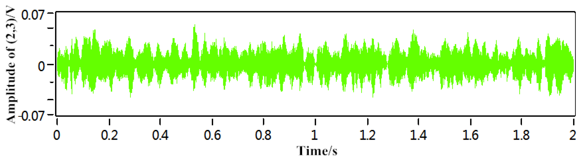
The vibration signal of the fault motor was collected by the sensor, which, after conditioning, is shown in Figure 10.
Then, the improved wavelet packet algorithm was used to decompose the vibration signal into four wavelet packet nodes: (2, 0), (2, 1), (2, 2) and (2, 3). The results of reconstructing these wavelet packet nodes are shown in Figure 11.
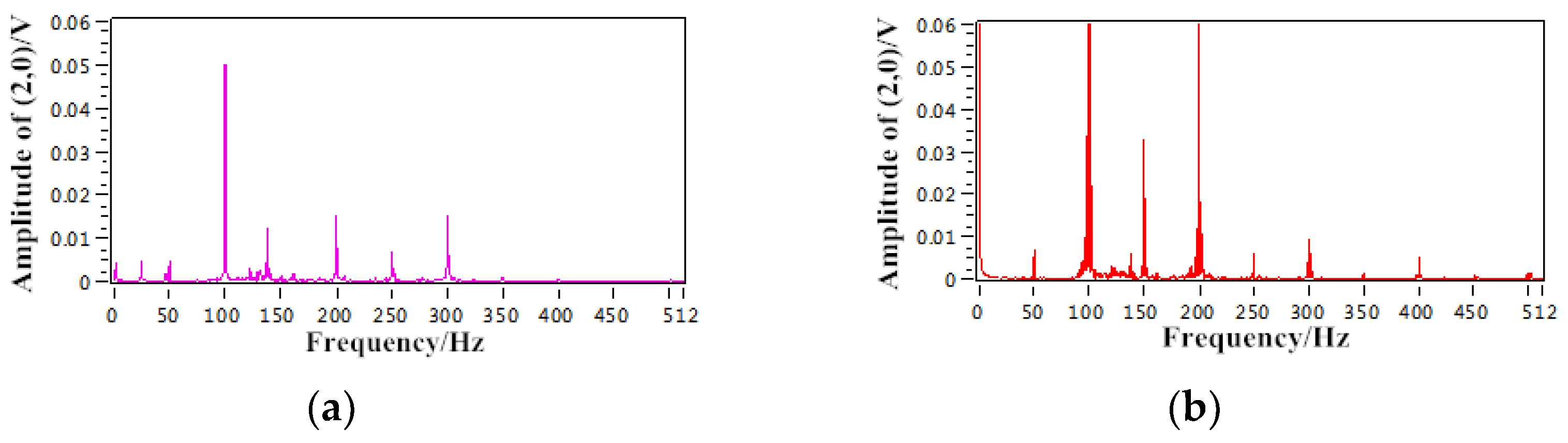
To observe the frequency distribution, the reconstructed nodes were transformed by FFT and compared with the results of normal motor signals. As shown in Figure 12, the changes of the frequency at (2, 0) are obvious.
Compared with the frequency spectrum of the normal motor, the amplitude of the fault motor in the fundamental frequency, 2fs = 100 Hz, is obviously increased. In addition, the amplitudes of the harmonic components at the frequencies of 3fs = 150 Hz, 4fs = 200 Hz and 8fs = 400 Hz increased.
4. Discussion
With the fault characteristics extracted from current signal and vibration signal analyzed synthetically, the fault of stator inter-turn short circuit of PMSM can be judged accurately. However, after extracting fault features, human beings are still necessary to identify them. Artificial intelligence technology needs to be used in the research of motor fault diagnosis in the future.
5. Conclusions
In this work, a detection method based on stator current and vibration signal has been presented to stator inter-turn short circuit fault of PMSM. The increased harmonic components in the current signal and vibration signal can be characterized to detect the fault of PMSM. These two fault features are considered in this paper. At the same time, the improved wavelet packet analysis is used to get the fault features, which can analyze the signal in time–frequency domain and has the advantage of eliminating spectrum aliasing. The validity of this method is verified by experiments on the fault diagnosis platform of motor.
In the future, artificial intelligence and deep learning will be used to diagnose motor faults, such as the convolutional neural network (CNN). This does not require much prior knowledge and can extract the fault characteristics that are more accurate.
Author Contributions
Conceptualization, H.L. and Y.C.; methodology, H.L. and Y.C.; software, S.L.; validation, H.L. and S.L.; formal analysis, H.L. and S.L.; investigation, H.L.; resources, H.L.; data curation, H.L. writing—original draft preparation, H.L.; writing—review and editing, C.W.; visualization, S.L.; supervision, Y.C. and C.W.; and project administration, Y.C.; funding acquisition, Y.C.
Funding
This research was funded by the National key R & D Plan Program (2018YFB0106100), the National Natural Science Foundation (51607027), the Sichuan Science and Technology support Program (2016GZ0395, 2017GZ0395, and 2017GZ0394), and the Central University basic Research Business funds (ZYGX2016J140 and ZYGX2016J146).
Conflicts of Interest
The authors declare no conflict of interest.
References
- Mazzoletti, M.A.; Bossio, G.R.; Angelo, C.H.D.; Espinoza-Trejo, D.R. A Model-Based Strategy for Interturn Short-Circuit Fault Diagnosis in PMSM. IEEE Trans. Ind. Electron 2017, 64, 7218–7228. [Google Scholar] [CrossRef]
- Wang, Z.F.; Yang, J.; Ye, H.; Zhou, W. A review of Permanent Magnet Synchronous Motor fault diagnosis. In Proceedings of the IEEE Conference and Expo Transportation Electrification Asia-Pacific (ITEC Asia-Pacific), Beijing, China, 31 August–3 September 2014; pp. 1–5. [Google Scholar]
- Maraaba, L. An Efficient Stator Inter-Turn Fault Diagnosis Tool for Induction Motors. Energies 2018, 11, 653. [Google Scholar] [CrossRef]
- Li, Z.; Jiang, Y.; Hu, C.; Peng, Z. Recent progress on decoupling diagnosis of hybrid failures in gear transmission systems using vibration sensor signal: A review. Measurement 2016, 90, 4–19. [Google Scholar] [CrossRef]
- Glowacz, A. Fault diagnostics of acoustic signals of loaded synchronous motor using SMOFS-25-EXPANDED and selected classifiers. The. Vjesn. Tech. Gaz. 2016, 23, 1365–1372. [Google Scholar]
- Krolczyk, G.M.; Krolczyk, J.B.; Legutko, S.; Hunjet, A. Effect of the disc processing technology on the vibration level of the chipper during operations. The. Vjesn. Tech. Gaz. 2014, 21, 447–450. [Google Scholar]
- Glowacz, A.; Glowacz, W.; Glowacz, Z. Recognition of armature current of DC generator depending on rotor speed using FFT, MSAF-1 and LDA. Eksploat. i Niezawodn. Maint. Reliab. 2015, 17, 64–69. [Google Scholar] [CrossRef]
- Jiang, Y.; Zhu, H.; Li, Z. A new compound faults detection method for rolling bearings based on empirical wavelet transform and chaotic oscillator. Chaos, Solitons Fractals 2016, 89, 8–19. [Google Scholar] [CrossRef]
- Stavrou, A.; Sedding, H.G.; Penman, J. Current monitoring for detecting inter-turn short circuits in induction motors. IEEE Trans. Enrgye Convers. 2001, 16, 32–37. [Google Scholar] [CrossRef]
- Henao, H.; Demian, C.; Capolino, G.A.A. Frequency-domain detection of stator winding faults in induction machines using an external flux sensor. IEEE Trans. Ind. Appl. 2003, 39, 1272–1279. [Google Scholar] [CrossRef]
- Sdiri, F.; Bensalem, Y.; Trabelsi, H.; Abdelkrim, M.N. Inter-turn short-circuit fault detection in the vectorial control PMSM drive. In Proceedings of the 2017 18th International Conference on Sciences and Techniques of Automatic Control and Computer Engineering (STA), Monastir, Tunisia, 21–23 December 2017; pp. 362–367. [Google Scholar]
- Zheng, A.P.; Yang, J.; Wang, L. Fault Detection of Stator Winding Interturn Short Circuit in PMSM Based on Wavelet Packet Analysis. In Proceedings of the 2013 Fifth International Conference on Measuring Technology and Mechatronics Automation, Hong Kong, China, 16–17 January 2013; pp. 566–569. [Google Scholar]
- Çira, F.; Arkan, M.; Gümüş, B.; Goktas, T. Analysis of stator inter-turn short-circuit fault signatures for inverter-fed permanent magnet synchronous motors. In Proceedings of the IECON 2016—42nd Annual Conference of the IEEE Industrial Electronics Society, Florence, Italy, 23–26 October 2016; pp. 1453–1457. [Google Scholar]
- Zajac, M.; Sulowicz, M. Wavelet detectors for extraction of characteristic features of induction motor rotor faults. In Proceedings of the 2016 International Conference on Signals and Electronic Systems (ICSES), Krakow, Poland, 5–7 September 2016; pp. 212–218. [Google Scholar]
- Moosavi, S.S.; Esmaili, Q.; Djerdir, A.; Amirat, Y.A. Inter-Turn Fault Detection in Stator Winding of PMSM Using Wavelet Transform. In Proceedings of the 2017 IEEE Vehicle Power and Propulsion Conference (VPPC), Belfort, France, 11–14 December 2017; pp. 1–5. [Google Scholar]
- Obeid, N.H.; Boileau, T.; Nahid-Mobarakeh, B. Modeling and diagnostic of incipient inter-turn faults for a three phase permanent magnet synchronous motor using wavelet transform. In Proceedings of the 2015 IEEE Industry Applications Society Annual Meeting, Addison, TX, USA, 18–22 October 2015; pp. 1–8. [Google Scholar]
- Saucedo-Dorantes, J.J.; Delgado-Prieto, M.; Ortega-Redondo, J.A.; Osornio-Rios, R.A.; Romero-Troncoso, R.D.J. Multiple-Fault Detection Methodology Based on Vibration and Current Analysis Applied to Bearings in Induction Motors and Gearboxes on the Kinematic Chain. Shock Vib. 2016, 2016, 1–13. [Google Scholar] [CrossRef]
- Liang, Y. Diagnosis of inter-turn short-circuit stator winding fault in PMSM based on stator current and noise. In Proceedings of the 2014 IEEE International Conference on Industrial Technology (ICIT), Busan, South Korea, 26 February–1 March 2014; pp. 138–142. [Google Scholar]
- Li, Y.; Liang, Y. The correlation analysis of PM inter-turn fault based on stator current and vibration signal. In Proceedings of the 2015 IEEE International Conference on Mechatronics and Automation (ICMA), Beijing, China, 2–5 August 2015; pp. 1733–1737. [Google Scholar]
- Urresty, J.; Riba, J.; Romeral, L.; Rosero, J.; Serna, J. Stator short circuits detection in PMSM by means of Hilbert-Huang transform and energy calculation. In Proceedings of the 2009 IEEE International Symposium on Diagnostics for Electric Machines, Power Electronics and Drives, Cargese, France, 31 August–3 September 2009; pp. 1–7. [Google Scholar]
- Cruz, S.M.A.; Cardoso, A.J.M. Diagnosis of stator inter-turn short circuits in DTC induction motor drives. IEEE Trans. Ind. Appl. 2004, 40, 1349–1360. [Google Scholar] [CrossRef]
- Nandi, S.A. Detailed model of induction machines with saturation extendable for fault analysis. IEEE Trans. Ind. Appl. 2004, 40, 302–1309. [Google Scholar] [CrossRef]
- Ye, Z.M.; Wu, B. A review on induction motor online fault diagnosis. In Proceedings of the 2000 third International Power Electronics and Motion Control Conference, Beijing, China, 15–18 August 2000; pp. 1353–1358. [Google Scholar]
Figure 1.
The flow chart of the fast algorithm for binary wavelet packet decomposition.
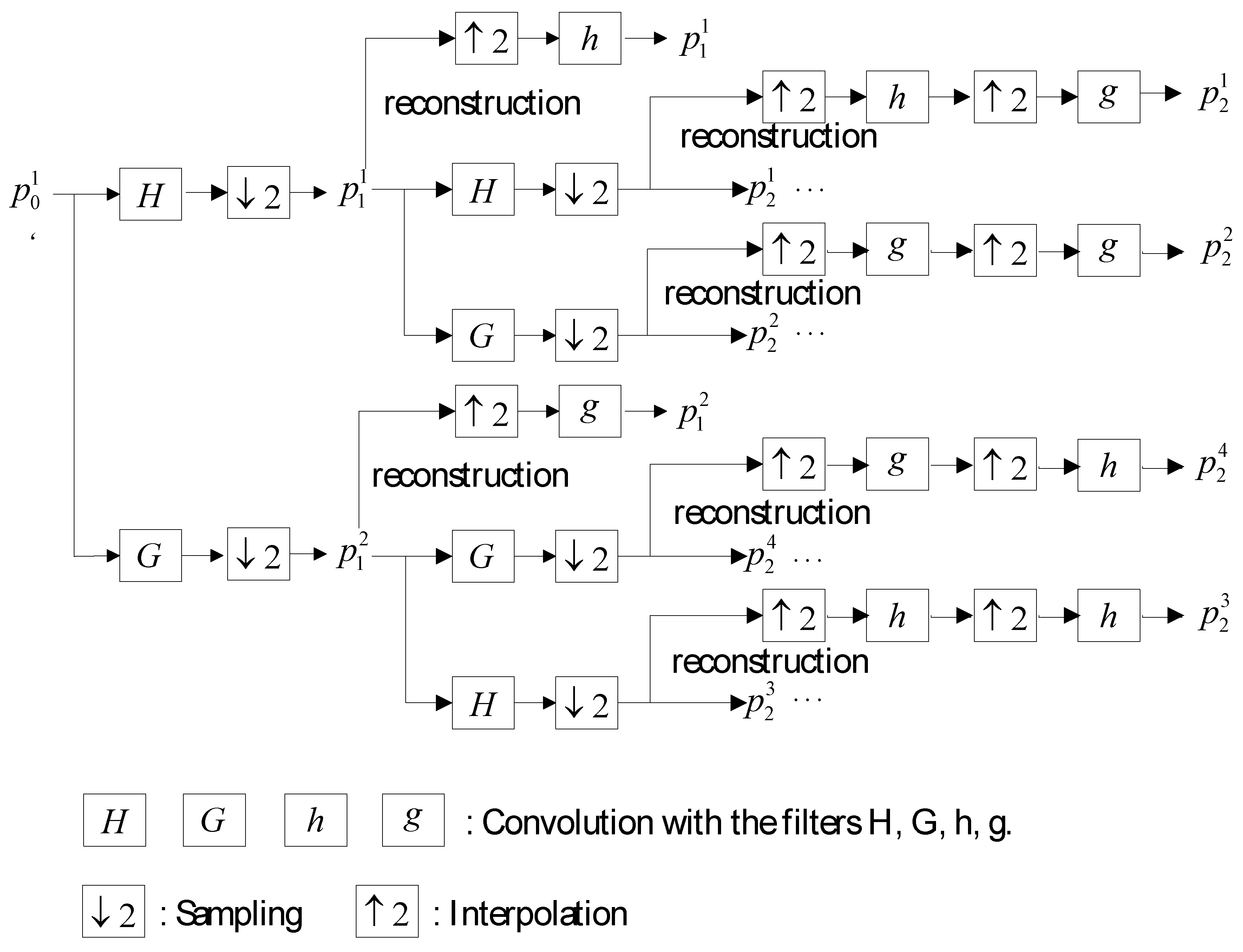
Figure 2.
The structure of experimental platform.
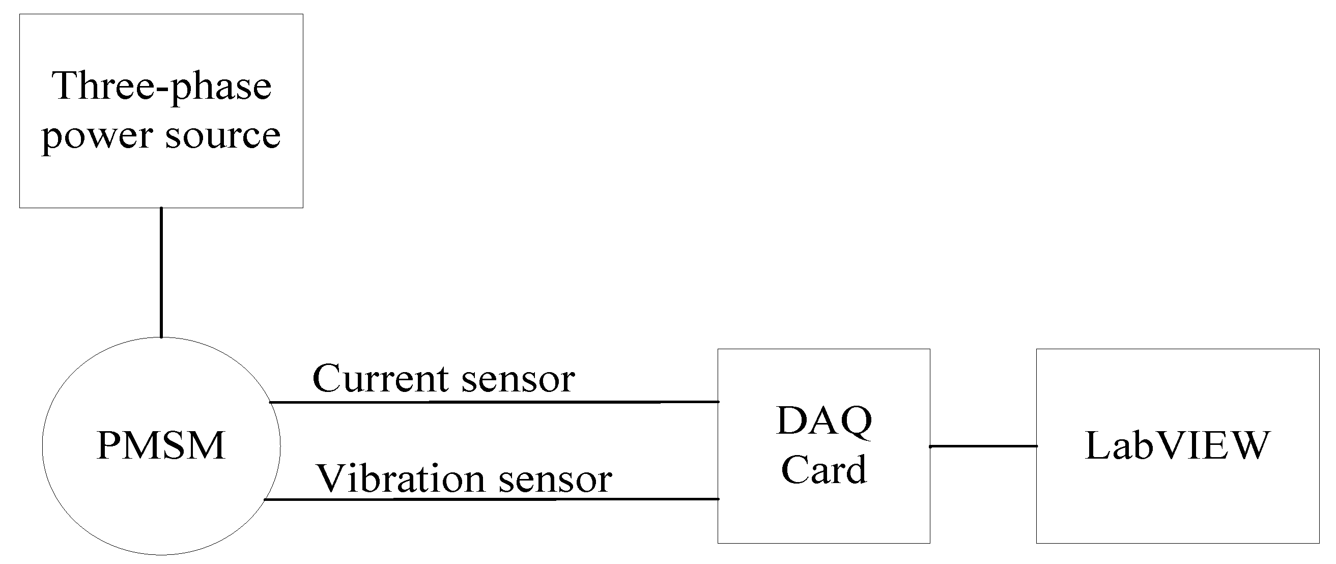
Figure 3.
The experimental platform for PMSM fault detection.

Figure 4.
The 90TDY115-2B permanent magnet low speed synchronous motor.

Figure 5.
LabVIEW program for fault detection.

Figure 6.
Improved wavelet packet algorithm.

Figure 7.
Three-phase current waveform of the fault motor.

Figure 8.
Reconstruction signals of the current of the fault motor.

Figure 9.
Spectrum diagrams of the current signal: (a) spectrum diagram of the normal motor; and (b) spectrum diagram of the fault motor.
Figure 9.
Spectrum diagrams of the current signal: (a) spectrum diagram of the normal motor; and (b) spectrum diagram of the fault motor.

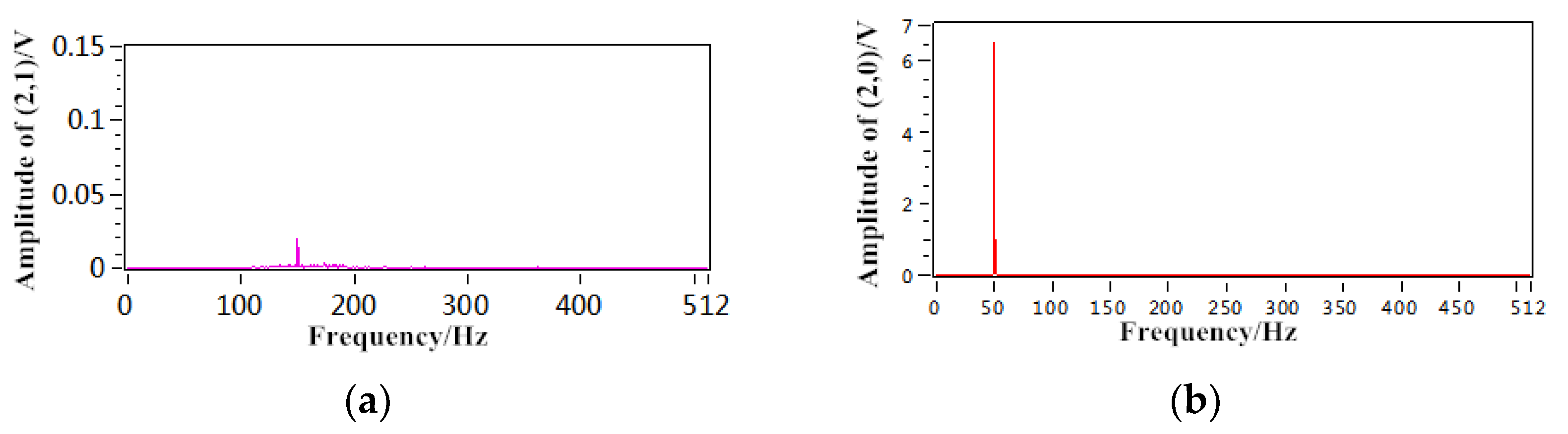
Figure 10.
The vibration signal of the fault motor.

Figure 11.
Reconstruction signals of the vibration of the fault motor.


Figure 12.
Spectrum diagrams of the vibration signal: (a) spectrum diagram of the normal motor; and (b) spectrum diagram of the fault motor.
Figure 12.
Spectrum diagrams of the vibration signal: (a) spectrum diagram of the normal motor; and (b) spectrum diagram of the fault motor.

© 2018 by the authors. Licensee MDPI, Basel, Switzerland. This article is an open access article distributed under the terms and conditions of the Creative Commons Attribution (CC BY) license (http://creativecommons.org/licenses/by/4.0/).
Share and Cite
MDPI and ACS Style
Liang, H.; Chen, Y.; Liang, S.; Wang, C. Fault Detection of Stator Inter-Turn Short-Circuit in PMSM on Stator Current and Vibration Signal. Appl. Sci. 2018, 8, 1677. https://doi.org/10.3390/app8091677
AMA Style
Liang H, Chen Y, Liang S, Wang C. Fault Detection of Stator Inter-Turn Short-Circuit in PMSM on Stator Current and Vibration Signal. Applied Sciences. 2018; 8(9):1677. https://doi.org/10.3390/app8091677
Chicago/Turabian StyleLiang, Hong, Yong Chen, Siyuan Liang, and Chengdong Wang. 2018. "Fault Detection of Stator Inter-Turn Short-Circuit in PMSM on Stator Current and Vibration Signal" Applied Sciences 8, no. 9: 1677. https://doi.org/10.3390/app8091677
Note that from the first issue of 2016, this journal uses article numbers instead of page numbers. See further details here.