Influence of Preheating Temperature on Cold Metal Transfer (CMT) Welding–Brazing of Aluminium Alloy/Galvanized Steel

1
School of Materials Engineering, Shanghai University of Engineering Science, Shanghai 201620, China
2
Shanghai Collaborative Innovation Center of Laser Advanced Manufacturing Technology, Shanghai 201620, China
*
Author to whom correspondence should be addressed.
Appl. Sci. 2018, 8(9), 1659; https://doi.org/10.3390/app8091659
Submission received: 20 August 2018
/
Revised: 10 September 2018
/
Accepted: 11 September 2018
/
Published: 14 September 2018
(This article belongs to the Special Issue Selected Papers from the NMJ2018)
Abstract
:Bead-on-plate cold metal transfer (CMT) brazing and overlap CMT welding–brazing of 7075 aluminium alloy and galvanized steel at different preheating temperatures were studied. The results indicated that AlSi5 filler wire had good wettability to galvanized steel. The preheating treatment can promote the spreadability of liquid AlSi5. For the overlap CMT welding–brazed joint, the microstructure of the joint was divided into four zones, namely, the interfacial layer, weld metal zone, zinc-rich zone, and heat affected zone (HAZ). The load force of the joints without preheating and 100 °C preheating temperature was 8580 N and 9730 N, respectively. Both of the joints were fractured in the fusion line with a ductile fracture. Further increasing the preheating temperature to 200 °C would decrease the load force of the joint, which fractured in the interfacial layer with a brittle fracture.
1. Introduction
The growing demand for lightweight design in the automotive industry arises a strong interest in the joining of aluminium alloy to steel. It is difficult to obtain a sound joining of aluminium to steel because of the large differences in the melting points, the coefficient of the thermal conductivity, and thermal expansion, especially the formation of intermetallic compound (IMC) at the Fe/Al interface. According to the Al–Fe phase diagram, the formation of IMC was inevitable during welding, due to the poor solubility between Fe and Al [1,2,3]. However, an excessive formation of IMC resulted in the brittleness in the joints. The published results showed that the thickness of IMC should be below 10 μm, which was the critical value in order to obtain good mechanical properties in Fe/Al dissimilar metal welding [4,5].
The total thickness of the IMC was primarily dominated by thermal diffusion and was related to the thermal cycle (i.e., peak temperature and duration) of the welding process [6]. The arc welding–brazing process combined the advantages of welding and brazing. Therefore, it was a preferable method to join aluminium alloy and steel, as it could suppress the growth of IMC and obtain good mechanical properties of Al/Fe joint. In this process, part of the aluminium alloy was melted, but the steel was in a solid state. The melted filler wire and aluminium alloy wetted the solid steel surface. Meanwhile, the Fe atoms diffused into the melted metal, and then IMC was formed at the interface of the steel/brazing metal.
Except for the thickness of IMC, the wettability and width of the wetting length were also critical factors influencing the mechanical properties of the joints in industrial manufacturing [7]. However, the wettability of liquid aluminium on a steel surface was fairly poor, due to the presence of an oxide layer on the surface of base material [8]. Usually, the oxide layer was removed by flux or a cathodic cleaning method so as to promote the wetting [7]. Moreover, the wettability can be improved by the zinc coatings and the preheating treatment on the steel sheet [9,10,11]. Therefore, galvanized steel was often used as a base material. The Zn coating is electro-galvanized or hot-dip galvanized. The thickness of coating is about 5–11 μm [7]. The spreadability of the Al-based droplets on the steel with preheating was greatly improved, which indicated that the preheating treatment process might be beneficial for obtaining a sound Al/Fe welding–brazed joint. In the metal inert gas (MIG) welding–brazing of Al/Fe with preheating treatment, H. Ma [10] and G. Qin [11] found that the preheating treatment process can increase the spreadablility of the weld seam and obtain a higher strength with a suitable preheat temperature.
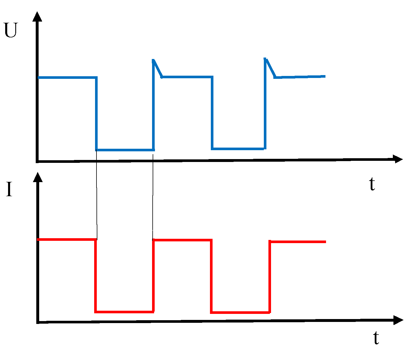
Cold transfer metal (CMT) is a modified process by MIG welding. In the CMT process, the filler wire is intentionally retracted instantaneously, which assists the droplet detachment during the short circuit. The short circuit current is kept small, as shown in Figure 1. Compared with the conventional welding processes, the melted metal can be transferred into the welding pool without the aid of an electromagnetic force. It is characterized by a low heat input and no-spatter welding, which is a preferable process to join Al and Fe, as reported by R. Cao [12] and Y.L Zhou [13].
From the above, the low heat input CMT welding–brazing process or preheating treatment can be used to increase the strength of the joint. Thus, the aim of this study was to investigate the feasibility and mechanism of joining aluminium and steel. The 7075-T651 aluminium alloy with a high strength (more than 538 MPa) and low density (2.81 g/cm3) is used, which is suitable for structures and components that are subjected to static and dynamic loads. Bead-on-plate CMT brazing was used to better understand the wetting characteristics of the brazing metal on steel. The microstructure and mechanical properties of the overlap CMT welding–brazing joints at different preheating temperatures were also investigated.
2. Experimental Methods
2.1. Materials and Procedure
The 7075 aluminum alloy with a thickness of 2.7 mm, and galvanized steel with a thickness of 2 mm, were used as base materials. The thickness of the Zn coating on galvanized steel was about 11 μm. ER4043 (AlSi5) with a diameter of 1.2 mm was used as a filler wire. The nominal chemical compositions of the base materials and the filler wire are listed in Table 1.
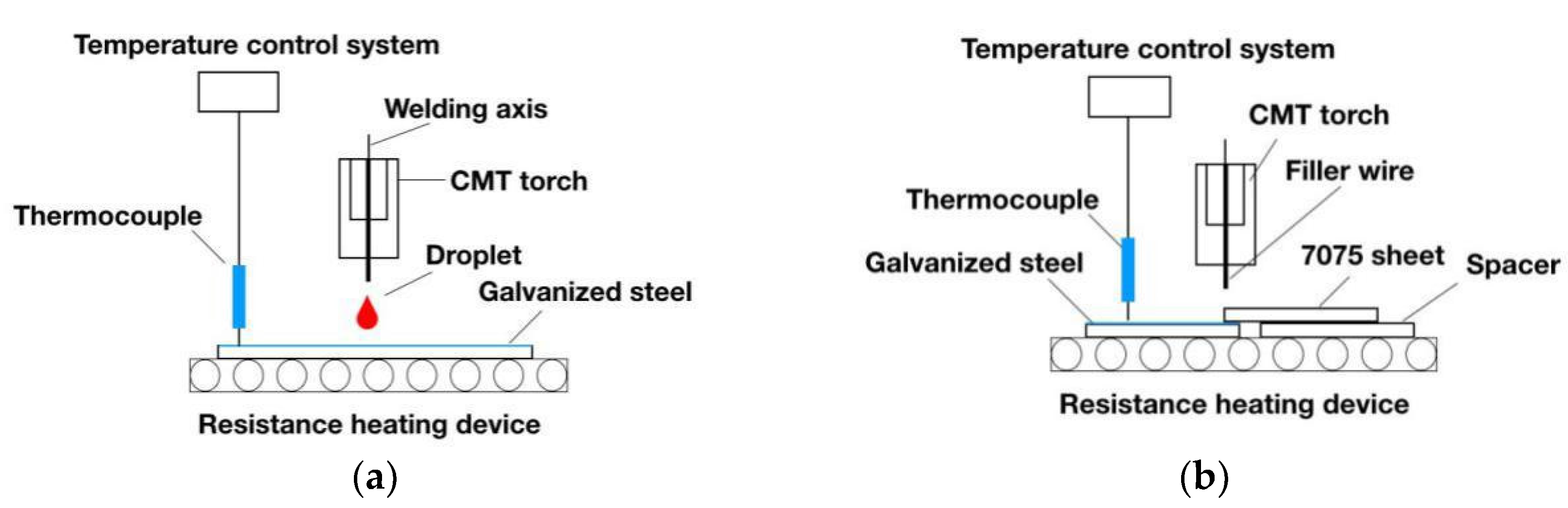
The size of the specimens was 150 mm × 100 mm × 2.7 mm and 150 mm × 100 mm × 2 mm for 7075 aluminum alloy and galvanized steel, respectively. The equipment was Fronius CMT 5000 i welding system. Before the experiment, the surface of the 7075 aluminum alloy was polished using SiC paper up to grit 1000, to remove the oxide films, and was ultrasonically cleaned by acetone. The galvanized steel was degreased by acetone to remove the grease. In case of bead-on-plate CMT brazing, AlSi5 filler wire was directly melted by a CMT arc, and dropped on the surface of the steel, as shown in Figure 2a. For the overlap welding–brazing of the aluminium alloy and steel, the aluminum alloy was placed on the top of the steel. The overlap length was 10 mm, as shown in Figure 2b.
Prior to the welding process, a heating resistance wire system equipped with temperature measurement and control was used to preheat the base materials. The heating plate was placed beneath the steel. The melting temperature of Zn is about 420 °C, and the strength of the Al/Fe MIG welding–brazed joint decreased when the preheating temperature was up to 200 °C, as reported by H. Ma [10]. The preheating temperature was chosen as 100 °C and 200 °C. In the welding process, argon, with a flow rate of 15 L/min, and a contact tip-to-work distance of 11 mm were used throughout the experiments. The bead-on-plate brazing and overlap welding–brazing processing parameters are given in Table 2. Considering the additional heat loss of the thermal conduction of the 7075 aluminium alloy during the overlap CMT welding–brazing, the welding speed was set at 0.4 m/min, lower than the 0.5 m/min welding speed in the bead-on-plate brazing.
2.2. Analysis Methods
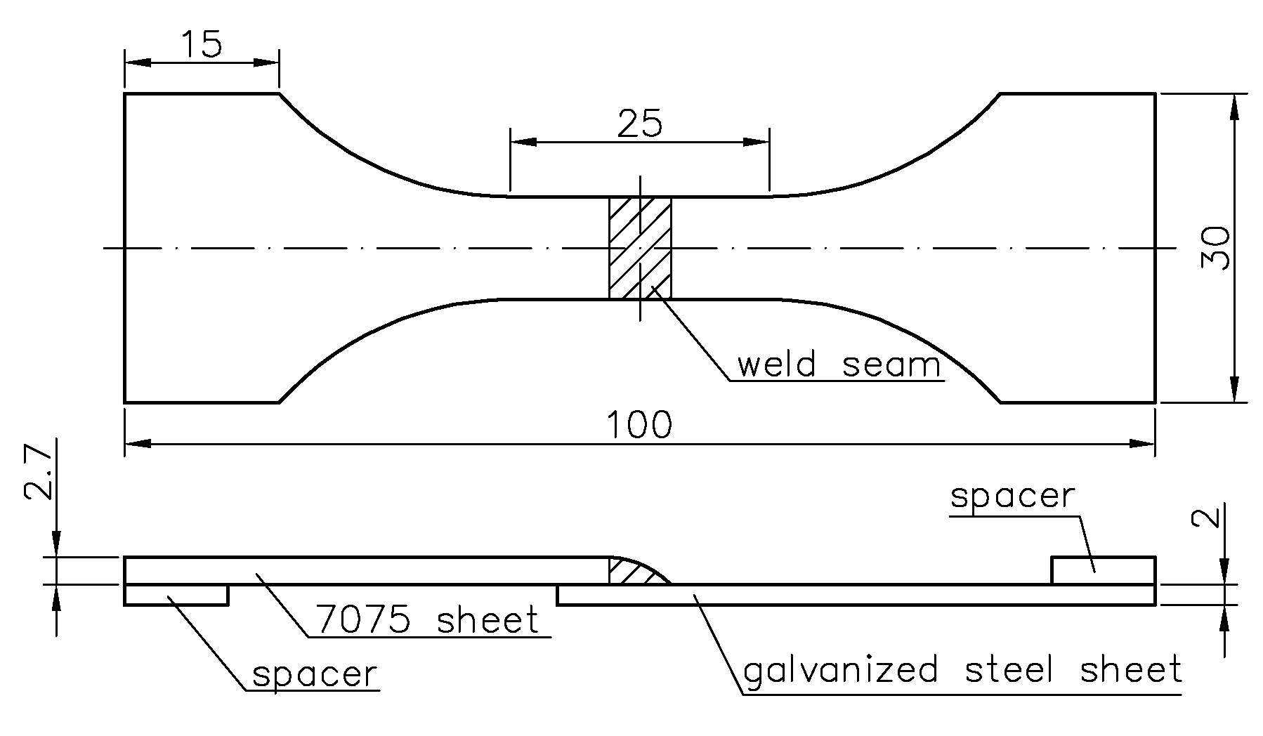
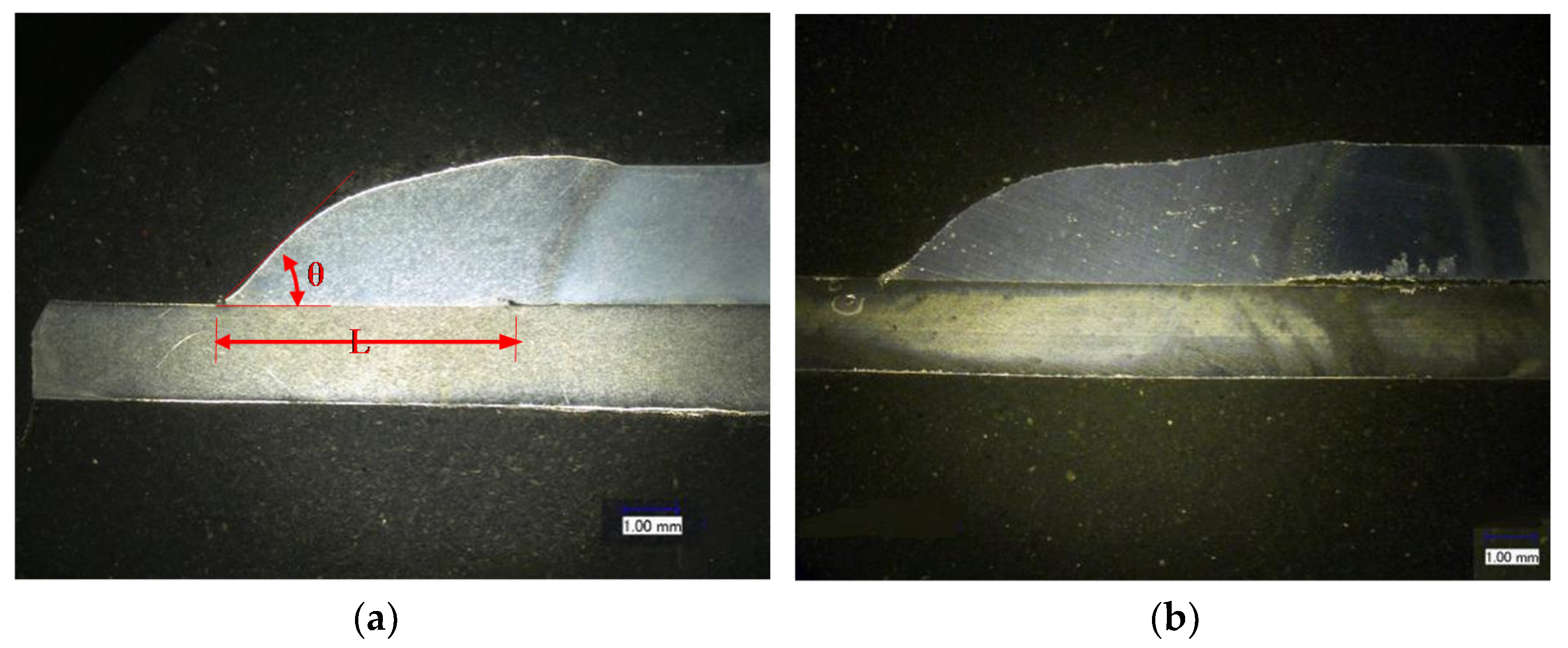
After joining, the width of the wetting length (L) and wetting angle () were measured on the cross sections of each seam. The width of the wetting length ranged from one triple point to the other triple point (bead-on plate brazing) or the welding root (overlap CMT welding–brazing). The wetting angle was determined to be the angle between the steel interface and the tangent applied along the outer bound of the spherical cap at a magnification of 100:1. The bead-on-plate brazing and overlap welding–brazing samples were polished for the microstructure evaluation. A scanning electron microscopy (SEM) coupled with an energy dispersive spectrometer (EDS) was used to characterize the joint. The tensile tests were done by an AG-25TA machine. The specimens were compressed at a constant speed of 1 mm/min, and the size of specimen is illustrated in Figure 3. At least three test specimens were used to obtain the average tensile force. The micro-hardness was tested by a Micro Vickers, at a load of 100 g for 15 s.
3. Results and Discussion
3.1. Wettability Characteristics of Bead-on-Plate Brazing
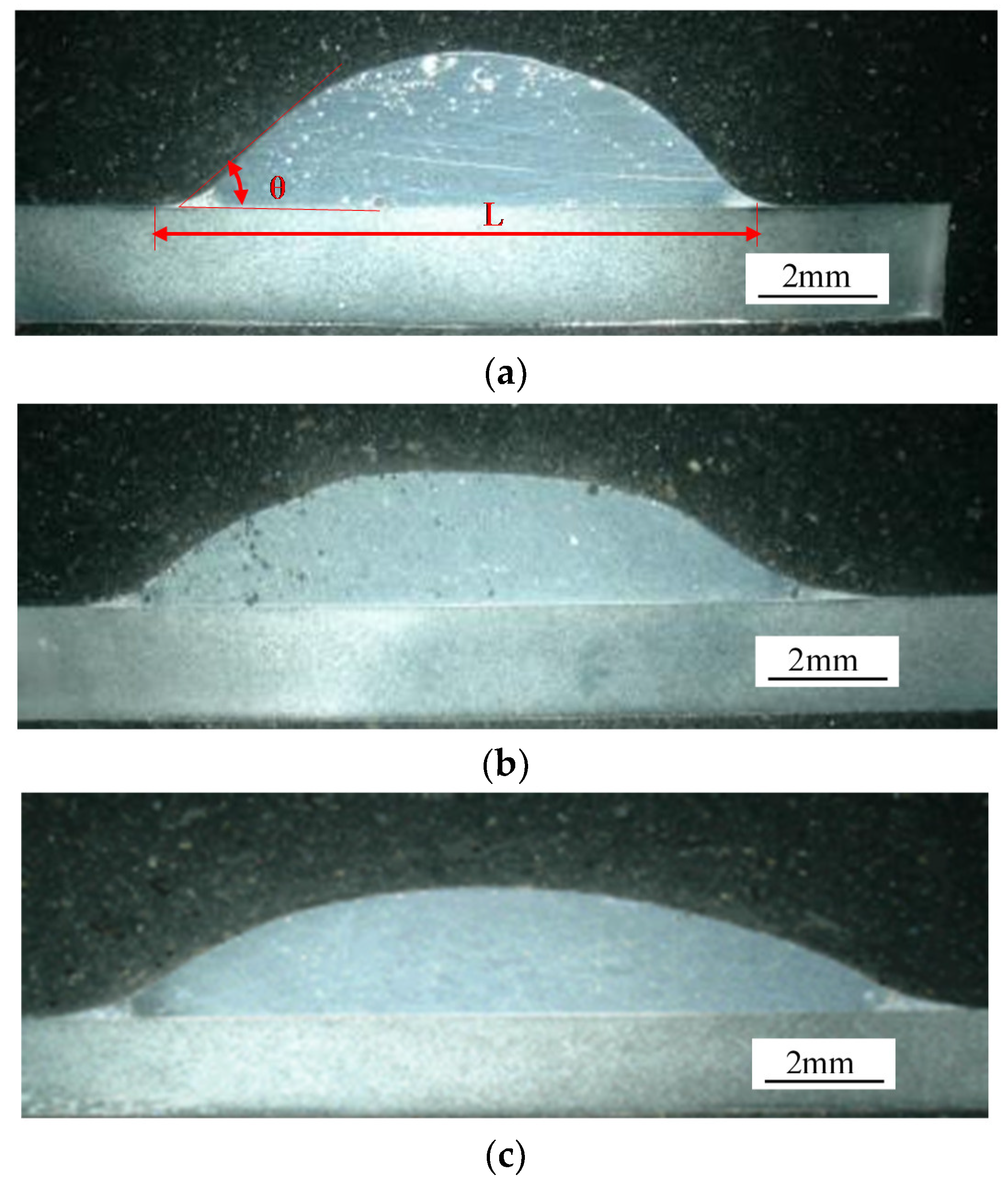
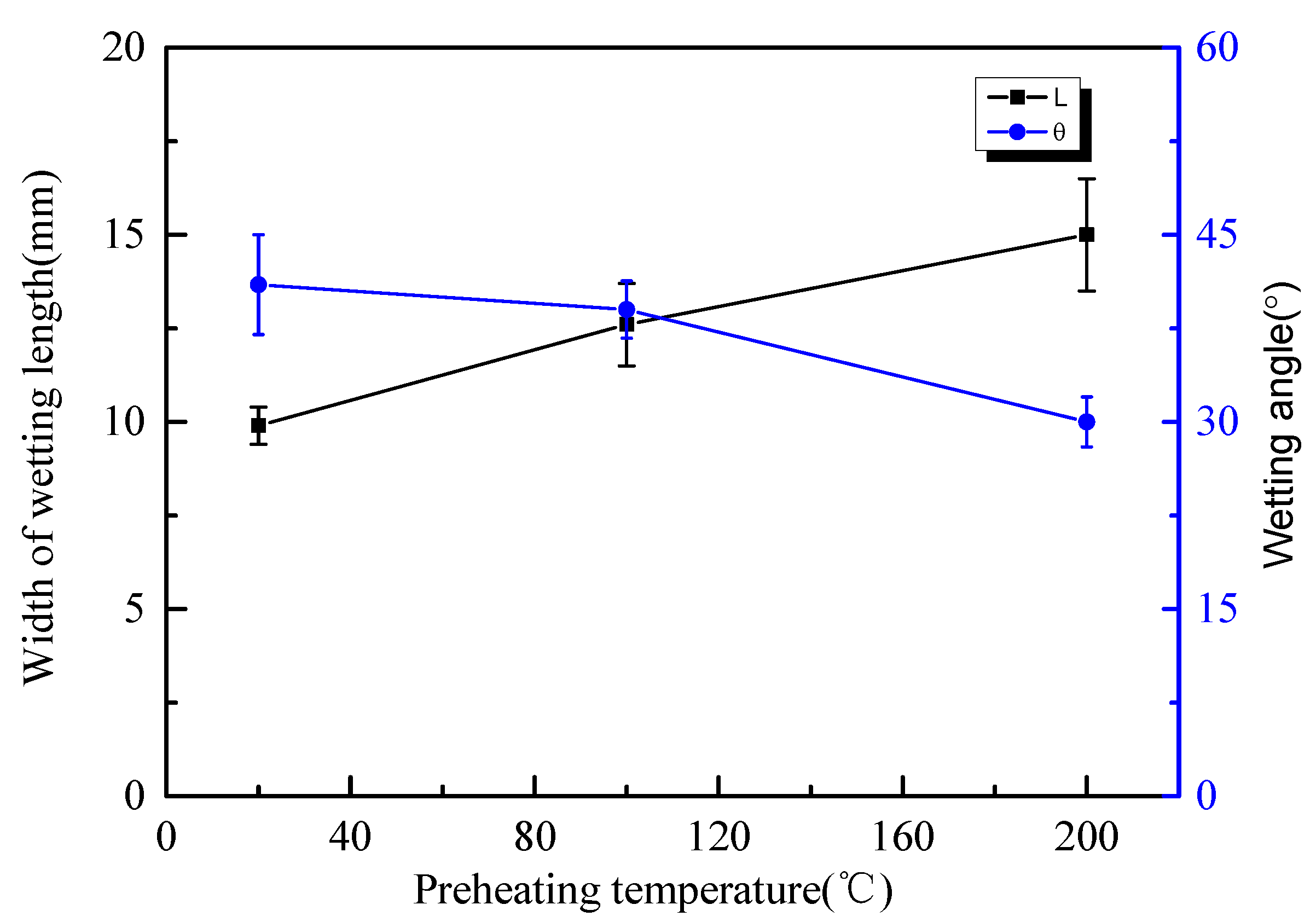
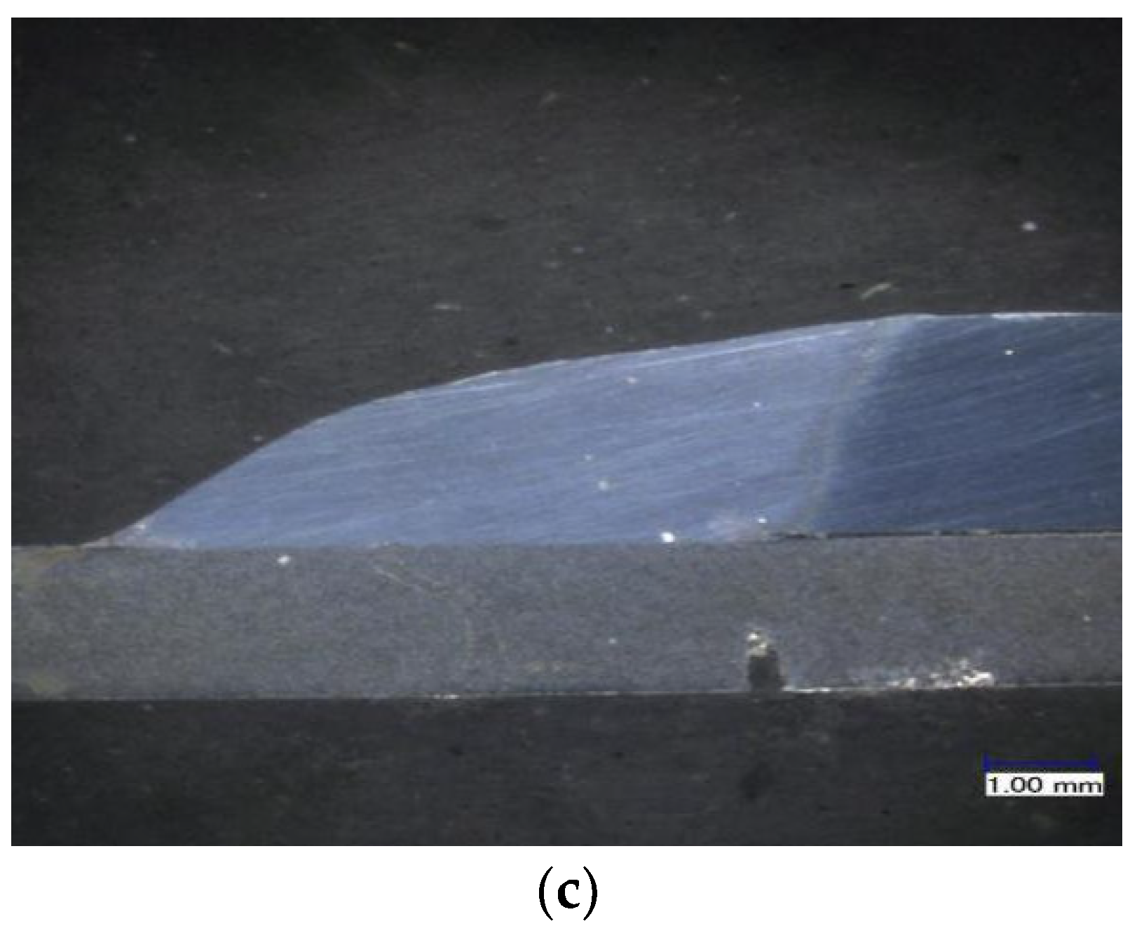
Metallographic cross sections of different bead-on-plate brazing specimens are shown in Figure 4. The width of the wetting length (L) and wetting angle () at different preheating temperatures are given in Figure 5. It was found that all of the wetting angles were below 90°. Compared with the joint without preheating, the width of the wetting length was longer and the wetting angle was lower with the preheating treatment. The width of the wetting length increased and the wetting angle decreased with the increasing preheating temperature. The minimum wetting angle (30°) and the maximum width of wetting length (15 mm) were obtained at a 200 °C preheating temperature. This indicated that the liquid AlSi5 filler wire had a good wettability on the galvanized steel. The preheating treatment could increase the spreading of the AlSi5 filler wire.
3.2. Influence of Preheating Temperature on the Overlap Welding–Brazing of Aluminium Alloy and Galvanized Steel
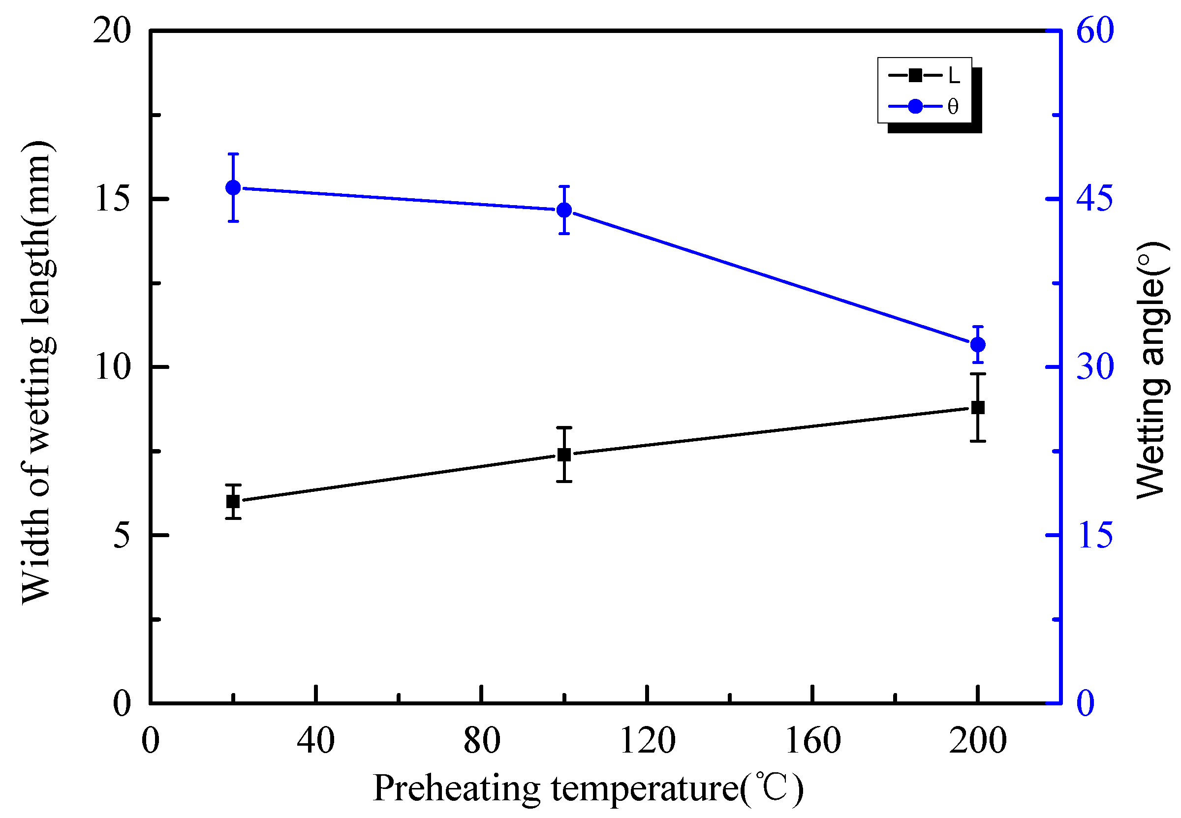
The cross sections of the overlap welding–brazing specimens are shown in Figure 6. The width of the wetting length (L) and wetting angle () at different preheating temperatures are given in Figure 7. As can be observed in Figure 6 and Figure 7, the wetting angles were higher and the widths of the wetting length were lower than those for the bead-on-plate brazing at the same preheating temperatures (see Figure 5). This was because the width of the wetting length or the wetting angle was influenced not only by the heat input of arc and preheating treatment, but also by the heat transfer of steel and aluminium. Compared with the bead-on-plate brazing, the extra and fast heat transfer by the 7075 aluminium alloy led to heat loss. Meanwhile, the variation tendency of the width of the wetting length and wetting angle with different preheating temperature was the same as bead-on-plate brazing. The variation trend was the same as the MIG welding–brazing reported in the literature [10].
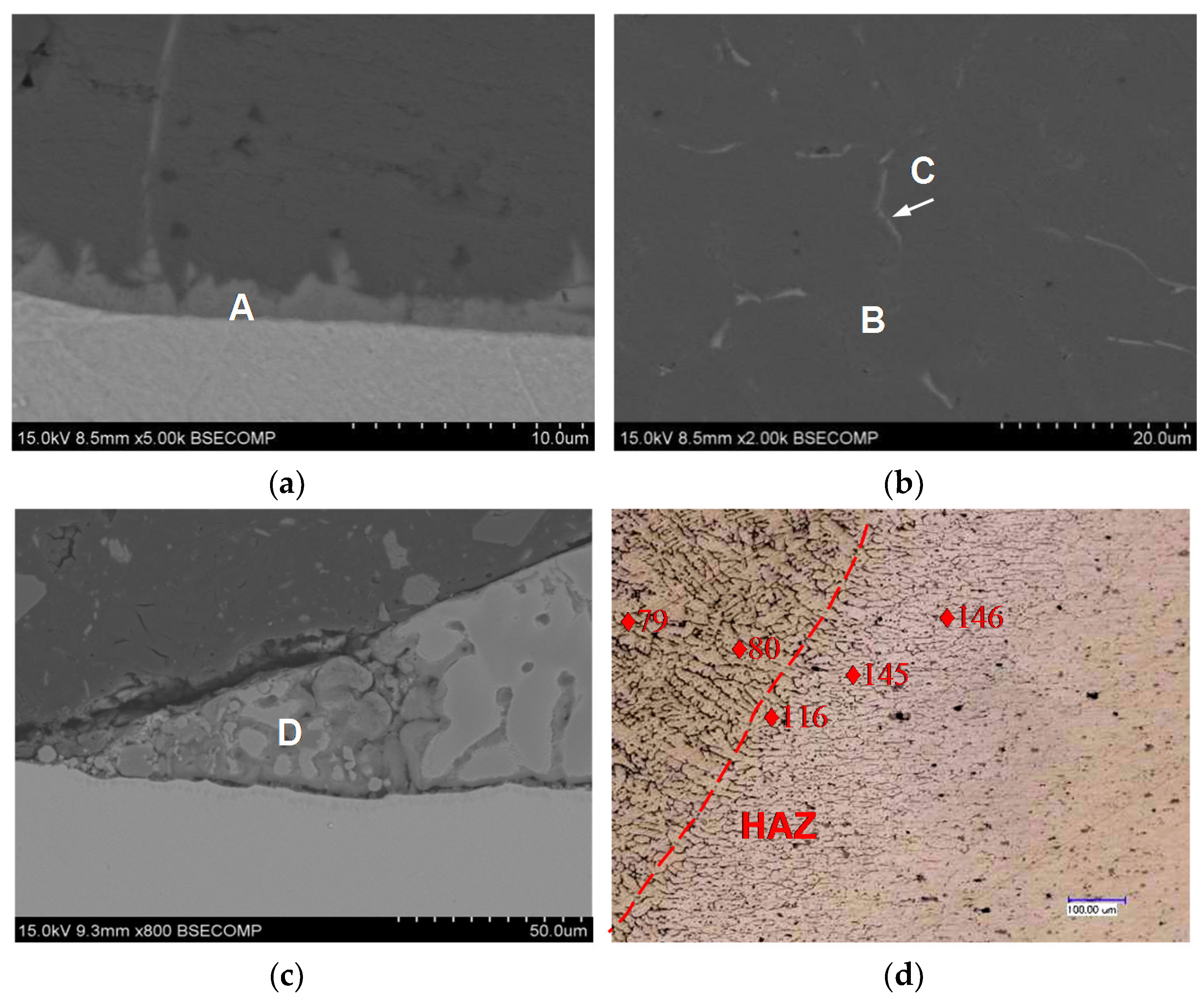
Figure 8 shows the typical microstructures of the CMT welding–brazing joint (without preheating). Table 3 gives the average chemical compositions of each zone. According to the microstructure features, the microstructures of the joint were divided into four different zones, namely: the interfacial layer, weld metal zone, Zn-rich zone, and heat affected zone (HAZ).
An irregular interfacial layer (A) occurred at the interface of the steel and brazing filler. From the EDS result, the interfacial layer mainly contained Al and Fe. No Zn was found in the interfacial layer. According to the phase diagram of Fe–Al [14], it was probably Fe–Al IMC. The thickness of the IMC layer was about 1.5 μm, as shown in Figure 8a. During the welding–brazing process, the arc heat melted AlSi5 filler wire and increased the temperature of the steel. The Zn coating within the region of the heavy heating was easy to evaporate, because of the low evaporating temperature of Zn. At the same time, a clean surface of the steel was obtained, which was beneficial to wetting. This was the main reason that the galvanized steel with a thin zinc layer on the surface was well wetted without flux.
Figure 8b shows the microstructure of the weld metal zone (B). B mainly consisted of Al and C was composed of 76.90 at.% Al and 20.03 at.% Si. Because the original filler wire was Al–5 wt.% Si. The microstructure of the weld metal was like the phases of the original filler wire. So B was ɑ-Al solid solution. C was Al–Si eutectic phase.
The Zn-rich zone (D) contained 70.38 at.% Al and 18.39 at.% Zn. According to the Al–Zn phase diagram [14], it was most likely an Al–Zn solid solution. The Zn-rich zone existed at the weld toe. Based on the characteristics of the arc, the temperature in the center of the arc was higher than the vaporization temperature of Zn. Little Zn was residual after the welding–brazing. However, in the edge of the arc, the temperature was probably lower than the vaporization temperature of Zn, and consequently, the Zn dissolved into the melted Al-based filler metal, forming Zn-rich phase (Figure 8c).
During the welding–brazing process, the microstructure of the base material near the weld metal zone was affected and changed by the heat conducted to the base material, as shown in Figure 8d. The phenomenon of the grain boundary melting occurred in the HAZ zone nearest to the weld metal. The hardness of the fusion line (about 116 HV0.1) and HAZ (about 146 HV0.1) is higher than that in the weld metal zone (79 HV0.1), as shown in Figure 8d. The minimum hardness is obtained in the weld metal zone, then the hardness increased rapidly to a higher level in the HAZ adjacent to the fusion line. The peak temperature of the HAZ nearest to the fusion line exceeds the fully dissolved temperature of the η and η’ phases. The η and η’ phases dissolve during welding and dissolve out in the cooling stage, thus the hardness of the HAZ nearest to the fusion line is about 146 HV0.1, which is lower than that of the base material (about 180 HV0.1). The fusion line is between the weld metal zone and the HAZ. The microstructure of the fusion line is very heterogeneous, thus it is one of the weaker regions of the joint.
Figure 9 gives the microstructures of the interfacial layer obtained at different preheating temperatures. Compared with the joint without preheating, the thickness of the interfacial layer slightly increased with the preheating temperature at 100 °C. By further increasing the preheating temperature at 200 °C, the thickness of the interfacial layer can be increased to 3.5 μm, which is lower than the thickness of the total layer (about 6 mm) at the 200 °C preheating temperature in the literature [10].
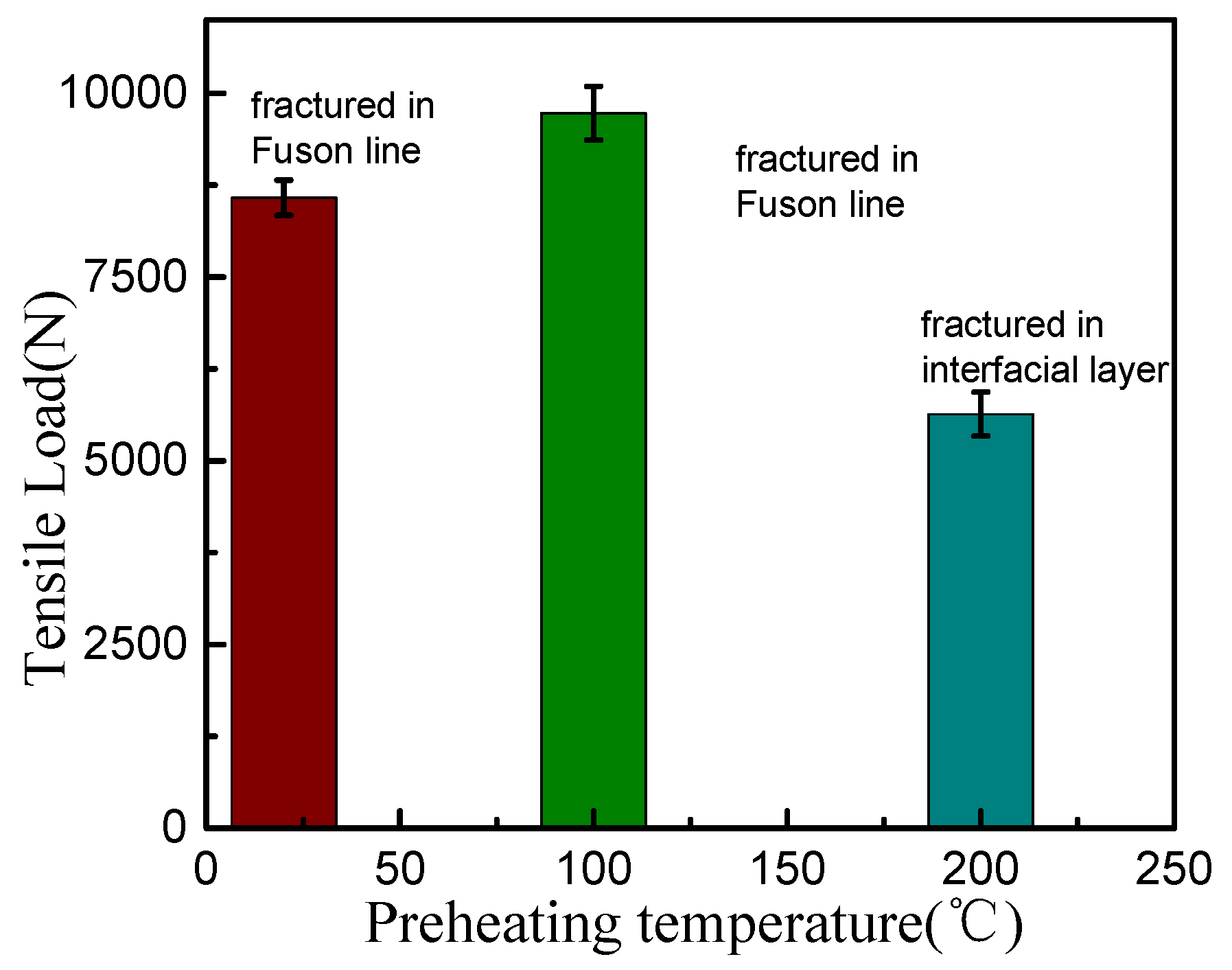
The mechanical properties, fracture location, and fracture surface at different preheating temperatures are shown in Figure 10 and Figure 11. The tensile load of the welding–brazed joint without preheating was 8580 N, and the tensile load obtained with a 100 °C preheating temperature was 9730 N. Both of the joints were fractured at the fusion line. This was because the thickness of the IMC was thin, the tensile force of the fusion line on the Al side was sufficient to cause the fracture before the tensile shearing force of the interfacial layer on steel side would cause fracture. Moreover, because of the preheating of the base materials to 100 °C, the cooling speed and welding stress of the joint decreased, which led to higher strength of the fusion line. But when the base materials were preheated to 200 °C, the tensile load decreased to 5636 N. The cracks occurred at the interfacial layer. Although the width of the wetting length at the 200 °C preheating temperature was larger than these recorded without preheating and at the 100 °C preheating temperature, the thicker IMC with the lower shear strength led to a low tensile load. Fracture surfaces of the joints displayed in Figure 11 indicated that a brittle fracture occurred at the IMC layer, while that in the fusion line was ductile.
4. Conclusions
In this paper, 7075 aluminium and galvanized steel were joined by CMT welding–brazing. The influence of the preheating temperature on the wetting characteristics of the bead-on-plate brazing, as well as the microstructure and mechanical properties of the overlap welding–brazing are investigated. The results are as follows:
In the case of bead-on-plate brazing, the melted AlSi5 filler wire had a good wettability to the galvanized steel. The preheating treatment decreased the wetting angle and significantly increased the width of the wetting length. Compared with the bead-on-plate brazing, the wetting angle of the overlap welding–brazing was large because of the high heat conductivity of the 7075 aluminium alloy.
There were four characteristic zones of overlap in welding–brazing joint, namely: the interfacial layer, weld metal zone, Zn-rich zone, and HAZ. The interfacial layer was Fe–Al brittle IMC. The thickness of the interfacial layer increased with the increased preheating temperature.
The tensile load of the joint without preheating was lower than that at a 100 °C preheating temperature. Both of them were fractured in the fusion line with a ductile fracture. Further increasing the preheating temperature to 200 °C would decrease the tensile load of the joint. The fracture occurred at the interfacial layer because of the thicker IMC layer.
Author Contributions
Y.Q.Q. and X.H. conceived and designed the experiments; W.X.Z. performed the experiments; Y.Q.Q. and X.H. arranged and analyzed the acquired data; Y.Q.Q. wrote the manuscript; The authors have all read and approved the submitted version of the manuscript.
Funding
This research was financially supported by the Shanghai Science and Technology Committee Innovation Grant (17JC1400600, 17JC1400601).
Conflicts of Interest
The authors declare no conflict of interest.
References
- Li, X.; Scherf, A.; Heilmaier, M.; Stein, F. The Al-Rich Part of the Fe-Al Phase Diagram. J. Phase Equilib. Diffus. 2016, 37, 162–173. [Google Scholar] [CrossRef] [Green Version]
- Pouranvari, M.; Abbasi, M. Dissimilar gas tungsten arc weld-brazing of Al/steel using Al-Si filler metal: Microstructure and strengthening mechanisms. J. Alloys Compd. 2018, 749, 121–127. [Google Scholar] [CrossRef]
- Pouranvari, M. Critical assessment: Dissimilar resistance spot welding of aluminium/steel: Challenges and opportunities. Mater. Sci. Technol. 2017, 33, 1705–1712. [Google Scholar] [CrossRef]
- Agudo, L.; Weber, S.; Wagner, J.; Eyidi, D.; Schmaranzer, C.H.; Arenholz, E.; Jank, N.; Bruckner, J.; Pyzalla, A.R. Intermetallic FexAly-phases in a steel/Al-alloy fusion weld. J. Mater. Sci. 2007, 42, 4205–4214. [Google Scholar] [CrossRef]
- Yang, S.; Zhang, J.; Lian, J.; Lei, Y. Welding of aluminum alloy to zinc-coated steel by cold metal transfer. Mater. Des. 2013, 49, 602–612. [Google Scholar] [CrossRef]
- Springer, H.; Kostka, A.; Payton, E.J.; Raabe, D.; Kaysser-Pyzalla, A.; Eggeler, G. On the formation and growth of intermetallic phases during interdiffusion between low-carbon steel and aluminum alloys. Acta Mater. 2011, 59, 1586–1600. [Google Scholar] [CrossRef]
- Gatzen, M.; Radel, T.; Thomy, C.; Vollertsen, F. Wetting and solidification characteristics of aluminium on zinc coated steel in laser welding and brazing. J. Mater. Process. Technol. 2016, 238, 352–360. [Google Scholar] [CrossRef]
- Gatzen, M.; Radel, T.; Thomy, C.; Vollertsen, F. The role of zinc layer during wetting of aluminium on zinc-coated steel in laser brazing and welding. Phys. Procedia 2014, 56, 730–739. [Google Scholar] [CrossRef]
- Liu, J.; Jiang, S.; Shi, Y.; Cong, N.; Chen, J.; Huang, G. Effects of zinc on the laser welding of an aluminum alloy and galvanized steel. J. Mater. Process. Technol. 2015, 224, 49–59. [Google Scholar]
- Ma, H.; Qin, G.; Wang, L.; Meng, X.; Chen, L. Effects of preheat treatment on microstructure evolution and properties of brazed-fusion welded joint of aluminum alloy to steel. Mater. Des. 2016, 90, 330–339. [Google Scholar] [CrossRef]
- Qin, G.; Lei, Z.; Su, Y.; Fu, B.; Meng, X.; Lin, S. Large spot laser assisted GMA brazing-fusion welding of aluminum alloy to galvanized steel. J. Mater. Process. Technol. 2014, 214, 2684–2692. [Google Scholar] [CrossRef]
- Cao, R.; Yu, G.; Chen, J.H.; Wang, P.C. Cold metal transfer joining aluminum alloys-to-galvanized mild steel. J. Mater. Process. Technol. 2013, 213, 1753–1763. [Google Scholar] [CrossRef]
- Zhou, Y.L.; Lin, Q.L. Wetting of galvanized steel by Al 4043 alloys in the first cycle of CMT process. J. Alloys Compd. 2014, 589, 307–313. [Google Scholar] [CrossRef]
- Baker, H.; Okamoto, H. ASM Handbook Volume 3: Alloy Phase Diagrams; ASM International: Materials Park, OH, USA, 1992. [Google Scholar]
Figure 1.
Variations of voltage and current with time during cold metal transfer (CMT) process.

Figure 2.
Schematic of CMT joints. (a) Bead-on-plate CMT brazing; (b) overlap CMT welding–brazing.

Figure 3.
Geometry of the specimen for tensile test.

Figure 4.
Metallographic cross sections for bead-on-plate brazing at different preheating temperatures. (a) Without preheating; (b) 100 °C; (c) 200 °C.
Figure 4.
Metallographic cross sections for bead-on-plate brazing at different preheating temperatures. (a) Without preheating; (b) 100 °C; (c) 200 °C.

Figure 5.
Width of wetting length and wetting angle at different preheating temperatures.

Figure 6.
Metallographic cross sections for overlap welding–brazing at different preheating temperatures. (a) Without preheating; (b) 100 °C; (c) 200 °C.
Figure 6.
Metallographic cross sections for overlap welding–brazing at different preheating temperatures. (a) Without preheating; (b) 100 °C; (c) 200 °C.


Figure 7.
Width of wetting length and wetting angle at different preheating temperatures.

Figure 8.
Microstructures of bead-on-plate brazing (without preheating): (a) interfacial layer; (b) weld metal zone; (c) Zn-rich zone; (d) heat affected zone (HAZ) zone.
Figure 8.
Microstructures of bead-on-plate brazing (without preheating): (a) interfacial layer; (b) weld metal zone; (c) Zn-rich zone; (d) heat affected zone (HAZ) zone.

Figure 9.
Microstructures of the interfacial layer at different preheating temperatures of (a) 100 °C; (b) 200 °C.
Figure 9.
Microstructures of the interfacial layer at different preheating temperatures of (a) 100 °C; (b) 200 °C.

Figure 10.
Tensile force and fracture position at different preheating temperatures.

Figure 11.
Fracture surface of the joints. (a) In the fusion line; (b) in the interfacial layer.


Table 1.
Nominal chemical composition of base materials and filler wire (wt.%).
| Materials | C | Si | Fe | Cu | Mn | Mg | Zn | Al |
|---|---|---|---|---|---|---|---|---|
| galvanized steel | 0.041 | 0.018 | Bal. | - | 0.187 | - | - | - |
| 7075 | - | 0.40 | 0.50 | 1.20–2.0 | 0.30 | 2.10–2.90 | 5.10–6.10 | Bal. |
| ER4043 | - | 4.5–6.0 | 0.80 | 0.30 | 0.05 | 0.05 | 0.10 | Bal. |
Bal.—balance
Table 2.
Processing parameters of the bead-on-plate brazing and overlap welding–brazing.
| Wire Feeding Speed (m/min) | Welding Speed (m/min) | Preheating Temperature (°C) | |
|---|---|---|---|
| Bead-on-plate brazing | 5 | 0.5 | Room temperature, 100, and 200 |
| Overlap welding–brazing | 5 | 0.4 | Room temperature, 100, and 200 |
Table 3.
Energy dispersive spectrometer (EDS) energy spectrum analysis.
| Location | Fe | Al | Zn | Si | Possible Phase |
|---|---|---|---|---|---|
| A | 18.56 | 71.34 | 0.5 | 9.60 | Fe–Al intermetallic |
| B | 0.78 | 96.68 | 0.64 | 1.9 | α-Al |
| C | 0.88 | 74.66 | 0.76 | 23.7 | Al–Si eutectic phase |
| D | 0.93 | 71.39 | 19.39 | 09.29 | Al–Zn solid solution |
© 2018 by the authors. Licensee MDPI, Basel, Switzerland. This article is an open access article distributed under the terms and conditions of the Creative Commons Attribution (CC BY) license (http://creativecommons.org/licenses/by/4.0/).
Share and Cite
MDPI and ACS Style
Qin, Y.; He, X.; Jiang, W. Influence of Preheating Temperature on Cold Metal Transfer (CMT) Welding–Brazing of Aluminium Alloy/Galvanized Steel. Appl. Sci. 2018, 8, 1659. https://doi.org/10.3390/app8091659
AMA Style
Qin Y, He X, Jiang W. Influence of Preheating Temperature on Cold Metal Transfer (CMT) Welding–Brazing of Aluminium Alloy/Galvanized Steel. Applied Sciences. 2018; 8(9):1659. https://doi.org/10.3390/app8091659
Chicago/Turabian StyleQin, Youqiong, Xi He, and Wenxiang Jiang. 2018. "Influence of Preheating Temperature on Cold Metal Transfer (CMT) Welding–Brazing of Aluminium Alloy/Galvanized Steel" Applied Sciences 8, no. 9: 1659. https://doi.org/10.3390/app8091659
Note that from the first issue of 2016, this journal uses article numbers instead of page numbers. See further details here.