Effect of Coil Width on Deformed Shape and Processing Efficiency during Ship Hull Forming by Induction Heating


1
School of Naval Architecture and Ocean Engineering, Huazhong University of Science and Technology, Wuhan 430074, China
2
Collaborative Innovation Center for Advanced Ship and Deep-Sea Exploration (CISSE), Shanghai 200240, China
3
Hubei Key Laboratory of Naval Architecture and Ocean Engineering Hydrodynamics (HUST), Wuhan 430074, China
*
Author to whom correspondence should be addressed.
Appl. Sci. 2018, 8(9), 1585; https://doi.org/10.3390/app8091585
Submission received: 13 August 2018
/
Revised: 24 August 2018
/
Accepted: 5 September 2018
/
Published: 7 September 2018
Abstract
:The main hull of a ship is made up of a large number of plates with complex curvatures. Line heating is one of the main approaches used in the forming of a ship hull plate. Because line heating is based on manual heating using a handheld oxyacetylene gun, the typical heating width is extremely narrow. With the development of computer control technology, a newly developed automated plate forming equipment is available and its heat source is typically an electromagnetic induction coil. The temperature field and the induction coil size are correlated. However, investigations into the induction coil size are scarce. In this study, the effect that the induction coil width has on both the forming shape and processing efficiency is investigated via simulation and test. The results show that a moderate expansion of the induction coil width at different input powers has an insignificant impact on forming shapes that is attainable by common line heating. However, as the heating width expands with the expansion of the induction coil width, the number of the processing lines via line heating is reduced which improves the processing efficiency.
1. Introduction
During ship manufacturing, many plates with complex curvatures must be formed for the main hull of a ship, which is a time-consuming process. During this process, the line heating method creates local contraction deformation in a plate via a localized heating source, of which width is significantly narrower in size than the plate length or width as this processing method is based on moving a handheld oxyacetylene gun over a processed plate. In addition, it is believed that a narrower flame is beneficial to the formation of plate shapes with small curvatures. This method is widely deployed.
It is difficult to control the heat input when using a flame heat source. For line heating-based automated forming equipment, an electromagnetic induction heating has become a new heat source for the hot forming of ship hull plates because it is easy to control. Ueda [1,2] investigated the pattern of ship hull plates forming by line heating, discussed the heating line deployment principle and the heating criteria based on the theory of inherent strain, and verified and modified the path produced via induction heating. This work laid the foundation for the development of automated line heating forming equipment for ship hull plates. With the successful development of an automated system for ship hull plates forming by line heating [3], induction heating devices are gradually replacing manual oxyacetylene guns and are becoming a common heat source in line heating processing. Induction heating generates an eddy flow in the target material via an induction current with a specific frequency and provides heating via eddy flow heat conversion. Induction heating equipment normally consists of an induction coil and an alternating current (AC) power source. Here, the size of an induction coil is directly related to the heating area. Therefore, the induction coil size should be an important influencing factor for a forming process that uses induction-based line heating. Bae [4] investigated induction heating deformation with specific induction coil dimensions and provided a simplified equation for predicting transverse shrinkage and angular deformation. The equation contains heating parameters such as speed and power; however, the effect of the induction coil dimension is not addressed. Boadi [5] calculated an induction heating system in three dimensions and suggested that induction coil dimension parameters could be adjusted to achieve an optimal design for heat distribution; however, the relationship between the induction coil coverage area and the heating object deformation was not addressed. Pan [6] designed an induction coil shape via an empirical design method and investigated the effect of the coil shape under static heating. In some papers pertaining to the effect of special heating shapes on thick plate deformation, the temperature field and plate performance after heating improvement [7,8] and the relationship between the induction coil or temperature field and plate deformation were addressed to some extent. Hu [9] studied the shape parameters of the inductor and compared the processing efficiency during plate bending based on numerical experiments. Liu [10] studied the influence of coil shape and heating parameters on temperature field distributions during static heating. Wang [11] studied the influence of the cross-section parameters of the inductor on the temperature field and determined the main influence parameters of the coil using the experimental design method. However, there is no direct conclusion about the effect of the relative dimensions of the induction coil and the processed plate. Additionally, discussions of the effects on forming efficiency with the different dimensional induction coil are scarce.
Whether the dimensions of the induction coil can be adjusted moderately during the line heating process to expand the heat output range on the processed plate and thereby reduce the time required for forming without affecting the formed plate’s shape or dimensions is a problem worth investigating.
In this study, the plate temperature field and deformation field during induction heating are calculated via the finite element method. A test is performed to validate the finite element method. After the accuracy of the finite element method is validated, the effect of the induction coil sizes on the plate deformation shape and curvature distribution under induction heating, and the variation of processing efficiency versus induction coil sizes are investigated via numerical simulation. Here, Efficiency means the time required to process the same shape of a plate under different induction coil sizes.
2. Calculation and Experiment of Induction Heating
2.1. Finite Element Method Calculation
The entire calculation process is divided into three steps: electromagnetic calculation, heat transfer calculation and deformation calculation. The electromagnetic calculation is to obtain the heat flux distribution of the induction coil under specific conditions. COMSOL Multiphysics (Version 5.2, COMSOL Co., Ltd., Stockholm, Sweden) is used in this step to simulate the heat flux density along the two directions of the induction coil. The heat flux distribution calculated is then used as an input during heat transfer calculation in order to obtain the temperature field of the plate. The deformation calculation is to calculate the mechanical response of the plate under a specific temperature field. ABAQUS (Version 6.13-4, Dassault Systèmes, Vélizy-Villacoublay, France) is used during the last two steps. The overall process is illustrated in Figure 1.
The induction heating frequency used for ship hull forming is usually 8–50 kHz. When current flows through an inductor that is near a steel workpiece, an eddy current is induced at the surface of the plate. Induction heat is generated in the plate.
The eddy current during induction heating can be given by Maxwell’s equations in the frequency domain as [12]:
where stands for permeability, is the magnetic vector potential, is the angular velocity, is the electric conductivity and is the external current. The magnetic vector potential can be obtained from Equation (1) when the external current is given.
The resistance heat generated by the eddy current in the plate can be obtained as follows:
where refers to eddy current density and can be described as .
For induction heating, the eddy current generated inside the steel plate is mainly concentrated on the plate surface. For a plate during induction heating, the heat flux can be considered as a surface heat source and obtained as follows:
where refers to the heat flux on the surface of the steel plate and denotes the plate thickness.
The heat flux calculated before is used as the initial input for thermal analysis. The heat flow in a plate can be expressed as follows:
where refers to density, is the specific heat capacity, is the temperature of the plate and is the thermal conductivity. Thermal deformation calculation is followed after the temperature field, which is treated as the thermal load obtained from Equation (4).
The basic equations related to mechanical analysis are considered as follows:
where refers to stress tensor and represents the body force.
The stress–strain relationship can be expressed as:
where refers to the stress increment, is the elastoplastic matrix, is the strain increment, is the thermal stiffness matrix and is the temperature increment. Deformation of the plate can be obtained by solving the equations under actual boundary conditions.
The induction coil used in this study is shown in Figure 2. The entire coil is divided equally into three internal frames, as shown in Figure 2a. Considering plate bending deformation, the coil is designed to be slightly curved, and the horizontal curvature radius is 1000 mm. The coil projection outer edge width is LC = 220 mm, the outer edge length is LB = 200 mm, and LB is the direction of coil movement.
The dimensions of the plate are 1000 mm × 800 mm × 16 mm (L × B × t). The element type of the plate is DC3D8 for heat transfer simulation and C3D8R for deformation calculation. Fine grids are generated near the heating lines and the element size is 5 mm × 5 mm × 4 mm. Sparse grids are generated away from the heating lines and the element size is 50 mm × 20 mm × 8 mm. Transitional grids are generated between them and the whole model consists of 68,600 elements and 86,399 nodes. The rigid body displacement of the plate is constrained during the calculation.
2.2. Induction Heating Experiment
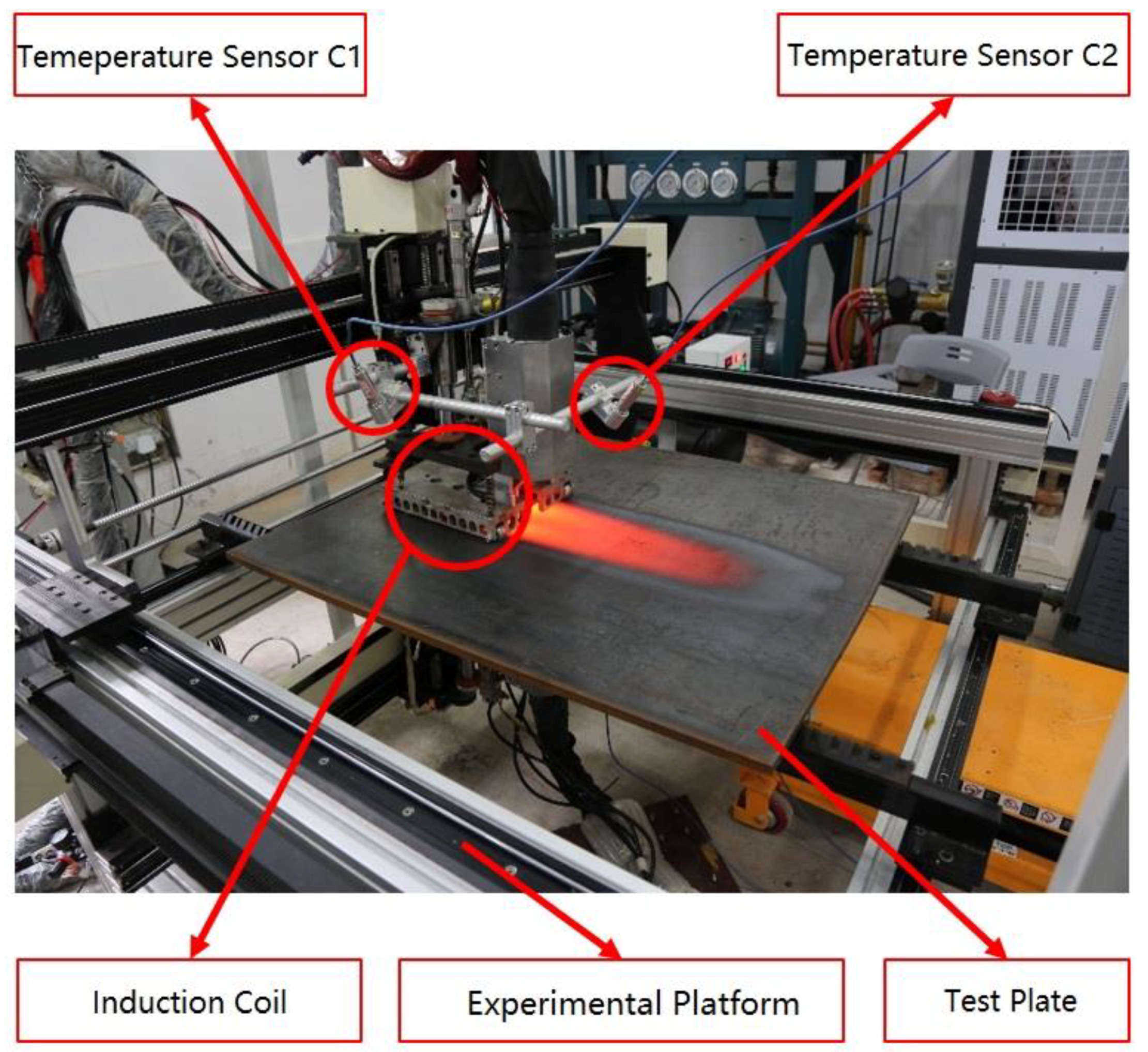
To verify the accuracy of the finite element method, an induction heating test is designed. In this test, an experimental platform made of triaxial motion of the coil is developed that can easily control the coil’s positioning, motion direction and travel speed over the test plate. The positioning precision of the experimental platform is 1 mm; and the controllable speed precision is 1 mm/s. To ensure a stable distance between the coil and the plate after plate deformation, the coil is embedded in the frame of a small vehicle, and the trolley wheel of the vehicle maintains rolling contact with the plate, which ensures no contact between the coil and plate, as shown in Figure 2b. For the initial condition, the lowest position of the coil center is 5 mm from the bottom of the trolley wheel. The experimental platform and test scenario are shown in Figure 3.
The test plate is carbon steel, of which major thermal, physical and mechanical properties are listed in Table 1 and Table 2 which is similar to Reference [13]. The plate dimensions are as follows: the length L = 1000 mm, the width B = 800 mm, and the thickness t = 16 mm. L is the coil movement direction over the plate. Here, LC/B = 0.275.
In the test, the heating line is the upper surface central line along the plate width direction (i.e., B/2). The coil length LB is aligned with the plate length L and is moved along the heating line. In the test, the electromagnetic induction frequency is 15 kHz, the heat source output power is 60 kW, and the coil travel speed is 5 mm/s. As the coil moves over the plate surface in a small rolling vehicle, the distance between the coil and the plate during heating is essentially constant.
In the test, the infrared temperature sensor (with a measurement range of 250–1450 °C) detects the plate temperature change during heating, as shown in Figure 3. Temperature sensors are deployed on one side and at the rear of the coil, and they move together with the coil, i.e., temperature sensors C1 and C2 in Figure 3. The point measured by C2 is 20 mm from the coil rear edge. A fixed temperature measurement point is deployed on one side of the plate to measure the temperature variation at the plate center T1. The final deformation of the plate is measured via a three-dimensional laser scanner measurement system after the entire plate cools to room temperature.
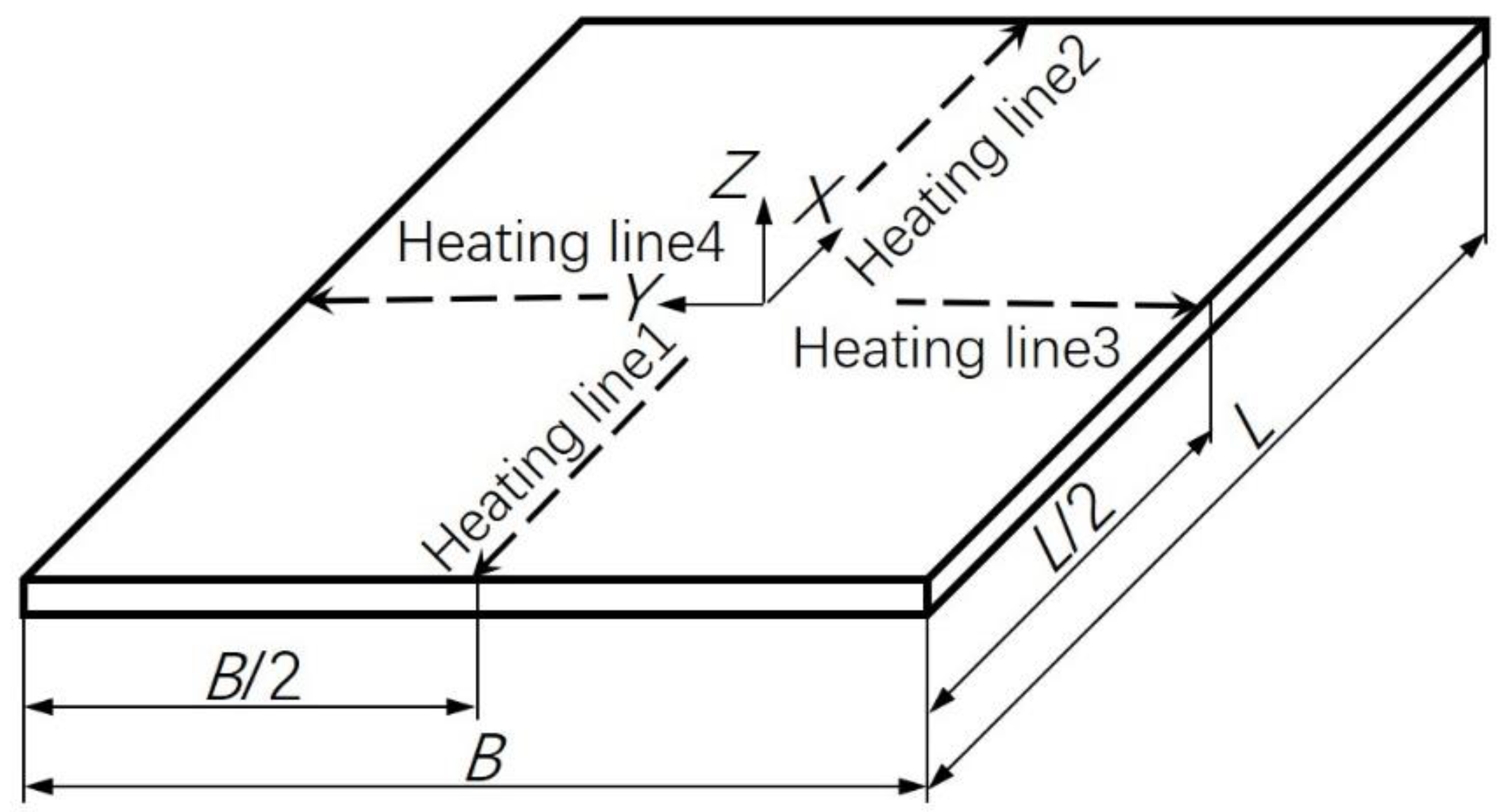
At the initial stage of the test, the entire coil is placed over the plate, and the trailing edge of the movement direction coincides with the plate’s rear end. As the coil moves continuously, the first notable phenomenon is the upward bending deformation of the plate along the B direction. In contrast, the plate deformation along the L direction is smaller and demonstrates a downward-bending trend. This phenomenon continues until the coil has completed its movement over the entire heating line. After the entire coil moves away from the plate and the plate temperature drops, the upward-bending deformation of the plate along the B direction changes slightly. However, the downward bending of the plate along the L direction gradually becomes prominent, and the plate eventually becomes saddle-shaped. In the study, similar tests are performed under other conditions with different plate thicknesses, heat source input powers and the coil movement speeds, with essentially the same results.
Although both the side ratio and shape of the coil and plate are close, the constraints from plate regions outside the heat expansion area on the coil-induced heat expansion of the plate are different along the L and B directions because the coil motion is directional; i.e., the coil moves along the plate’s L direction, as shown in Figure 4. Under the local contraction force PB along the B direction, the plate bends first along the B direction. Due to the deformation constraints of the plate itself and the heating movement direction, the contraction force PL along the plate’s L direction lags behind PB. As shown in Figure 4b, after bending, deformation occurs along the B direction, the PL resultant force (TL) is applied to the centroid of the B direction section, and a bending moment ML is created. Under ML, a deformation occurs along the plate’s L direction that is opposite to the plate’s B bending direction. This is why all of the shapes tested by the heating along the upper surface central line of the plate in the experiments are saddles.
2.3. Comparison between Experiment and Finite Element Method
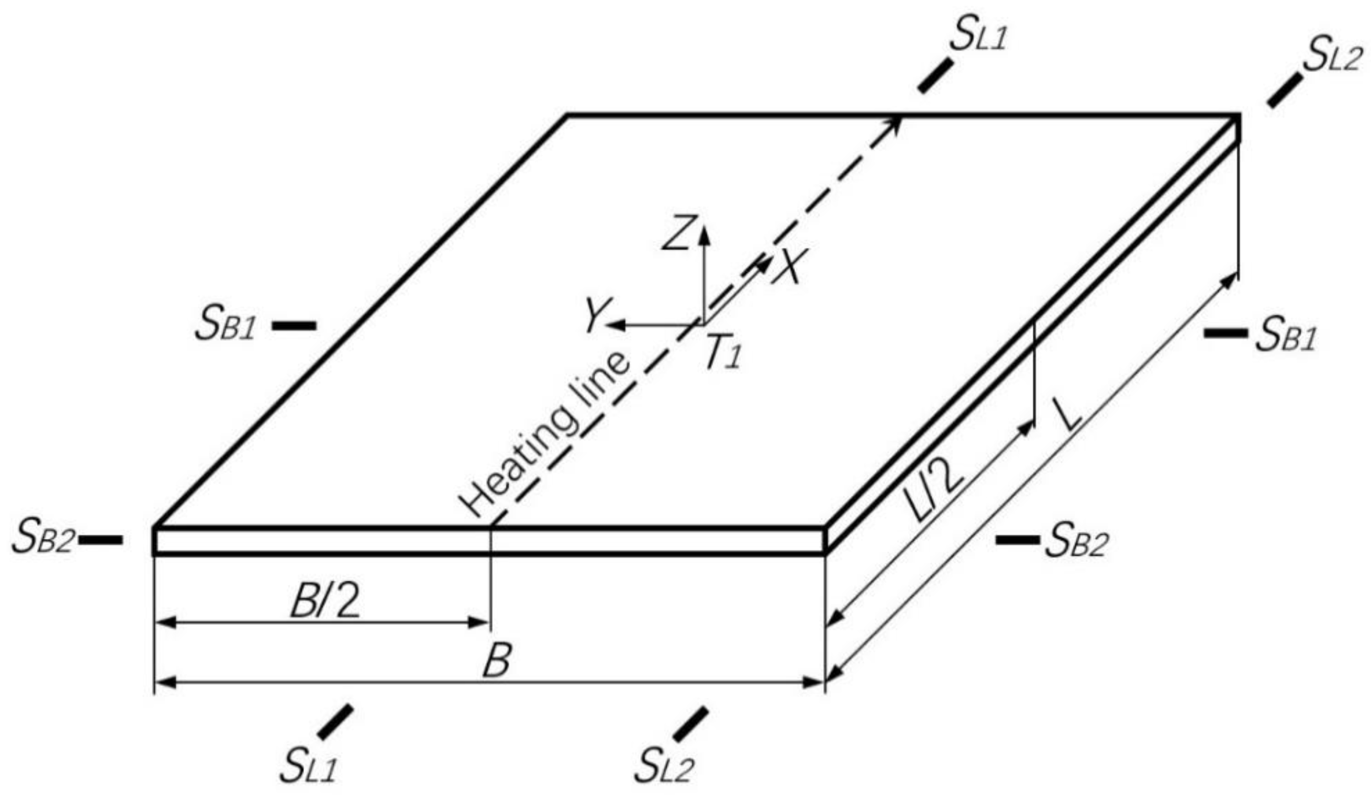
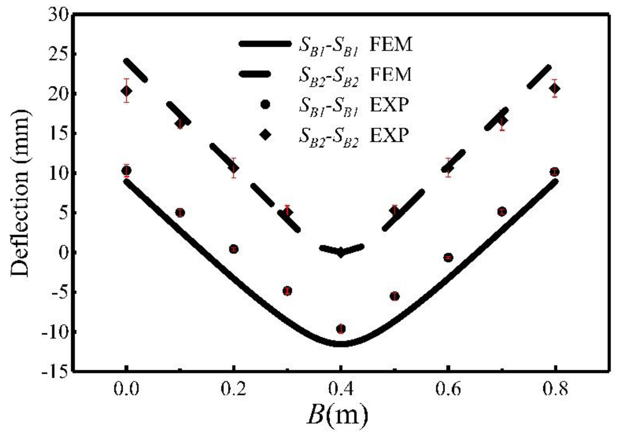
Several sections and points in Figure 5 are selected to compare the temperature and deformation from the finite element calculation with the test results. The sections include the SL1-SL1 section, which coincides with the heating line, the SL2-SL2 section at the plate end, which is parallel to the heating line, the SB2-SB2 section at the plate end, which is vertically oriented to the heating line and the SB1-SB1 section at L/2. The point selected is point T1 at the plate’s center.
Figure 6 compares the temperature variation from the finite element calculations with the test results at the plate’s central point, T1, during heating. The diagram shows that based on the coil’s dimensions, time record and speed, the relative position of the coil versus T1 at any moment can be derived. The finite element calculation results show that before 50 s, the temperature at T1 does not rise. Next, the temperature fluctuates in a small range and rises continuously until approximately 97 s. Thereafter, it declines steadily. The coil center passes T1 approximately 80 s after the beginning of the test. When the coil center and T1 coincide, the temperature at T1 is not at the highest level.
The finite element calculation shows that the temperature at T1 fluctuates slightly before reaching its highest level. There are two reasons for this: the coil panel is not continuous. Before passing T1, there is a large amount of heat dissipation from the coil toward the unheated “cold plate” in the front. After the coil passes T1, the “cold plate” before T1 becomes a “hot plate”, and the temperature at T1 declines steadily after a short period of fluctuation and increase. Additionally, because the temperature monitoring point at T1 is blocked by the moving coil near 80 s, the measurement data during this period are invalid. Because the temperature is measured at regular intervals (a discontinuous measurement method), small temperature fluctuations are not reflected. However, the finite element calculation results and the test data are closely related throughout the process. To further validate the finite element calculation method, data are collected from the temperature sensor C2 for comparison. The temperature variation versus time at C2 is the variation of the highest temperature at the plate heating line after 4 s (C2 is 20 mm from the coil edge, and the coil travel speed is 5 mm/s). The test results are compared with the finite element calculation and shown in Figure 7, which confirms that the two match closely.
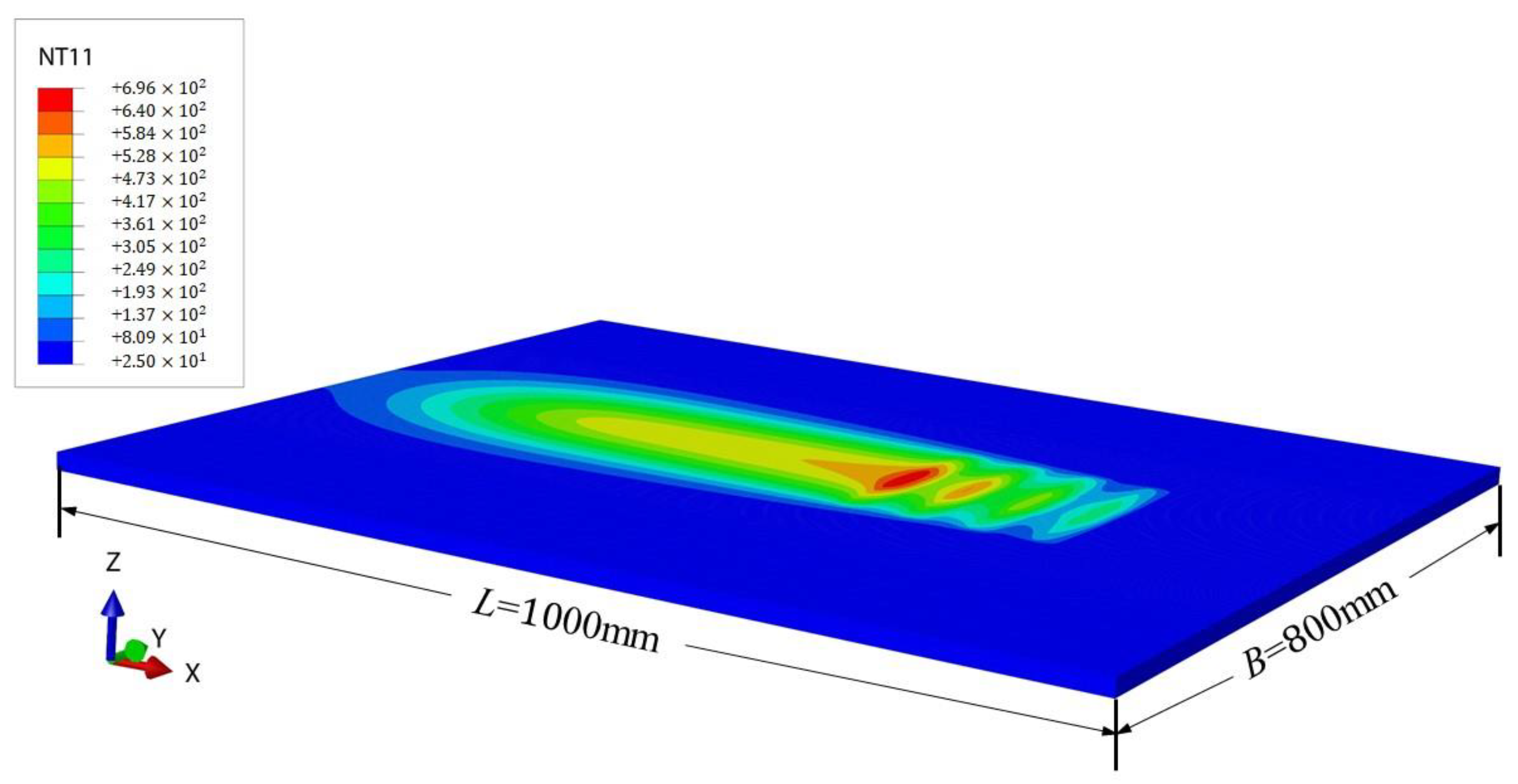
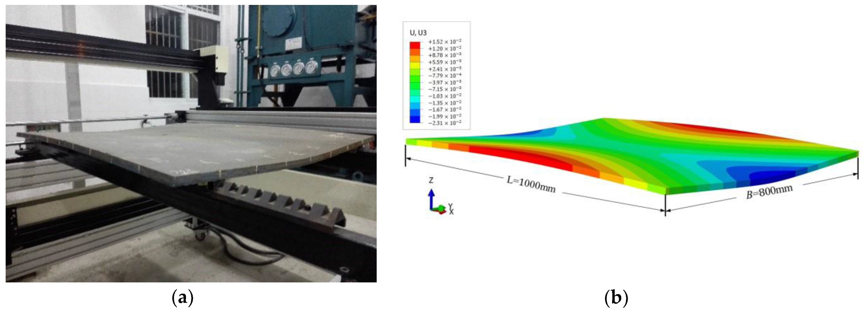
Figure 8 shows the heat distribution from the finite element model of heat transmission after heating for 115 s. The plate deformation shapes from the test and the finite element calculation are shown in Figure 9. Both results are saddle-shaped. Figure 10 and Figure 11 show the bending deformations of the heated plate in the transversal and longitudinal directions. The diagrams show that the finite element calculation and the test result have an excellent correlation. The maximum relative errors of the transversal and longitudinal deflections are approximately 10% and 9%, respectively, and both are located at the center of bending.
These results show that the current finite element computing model and method can accurately simulate plate deformation under induction heating.
3. Effect of Coil Width during Forming
Once the applicability of the finite element computing method has been validated by the test results, the finite element method is employed to study the effect of coil dimensions on forming shape and processing efficiency by modifying the coil dimension and calculating the number of heating lines required to produce a specific deformation shape in the plate.
To facilitate discussion, a square plate with equal length and width is considered, i.e., L = B. The plate length is L = 1000 mm, and its width is B = 1000 mm. The plate thickness has 2 options: t = 16 mm or t = 20 mm. Additionally, the coil outer edge length and width are equal, i.e., LC = LB. The form of the coil’s panel is chosen the same as in Figure 1a. The coil moves over the plate along the plate’s central line, which is the same as the test. Table 3 lists calculation schemes for different coil widths. Since both the plate and coil are square in shape, to facilitate representation, the parameter that reflects the dimension ratio of the coil versus the plate is defined as the ratio of their widths, i.e., LC/B. Normally, the coil width is always less than the plate width. Therefore, LC/B is less than 1. Five conditions are calculated, and the maximum coil width is approximately 1/3 of the plate width. The highest temperature produced by the coil in the scheme is the highest acceptable temperature for a heated plate in the heating forming of a typical ship hull plate.
3.1. Width Effect on Deformation
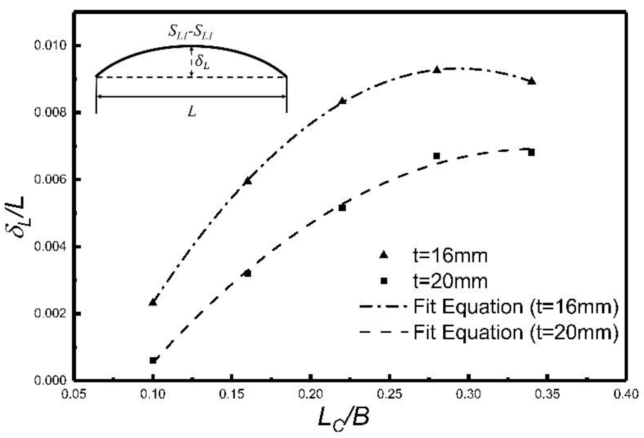
Figure 12 and Figure 13 show the plate deformations caused by line heating with coils of various sizes. In the diagrams, δB represents the maximum vertical deflection of the SB1-SB1 section in Figure 5, and δL represents the maximum vertical deflection of the SL1-SL1 section in Figure 5. Figure 12 and Figure 13 show that when the coil travel speed and highest temperature are fixed, within a large coil width variation range, the plate’s maximum transversal and longitudinal deflections increase with the coil dimension. Thus, the plate deformation increases with the coil dimension.
For plates with different thicknesses, the calculation results show similar patterns. The diagrams also show that when the coil dimension increases to a certain level, the increasing trend of transversal deflection gradually slows. For longitudinal deflection, when LC/B > 0.3 and as the coil dimension continuously increases, the bending deflection demonstrates a declining trend. This occurs because for the transversal deflection, the distance between the heating surface of the coil and the upper surface of the deformed plate increases as the coil width increases. Hence, although the temperature at the heating line of the plate is fixed in the calculation, the high-temperature effective range decreases as this distance increases. Therefore, the deflection increase rate slows. For longitudinal deflection, as shown in Figure 4, the distance from section TL to the B-direction section centroid decreases, which reduces the bending moment ML and thus reduces the deflection in the L direction. The result shows that when coil size increases to a certain level, it is possible that heating gradually causes changes in the local characteristics, which gradually weakens the local deformation characteristics of the plate.
The calculated effects of the coil width on the plate curvature are shown in Figure 14. The diagrams show that as coil size increases, the transversal maximum curvatures and curvature ranges increase accordingly.
3.2. Forming Capacity of a Wider Coil
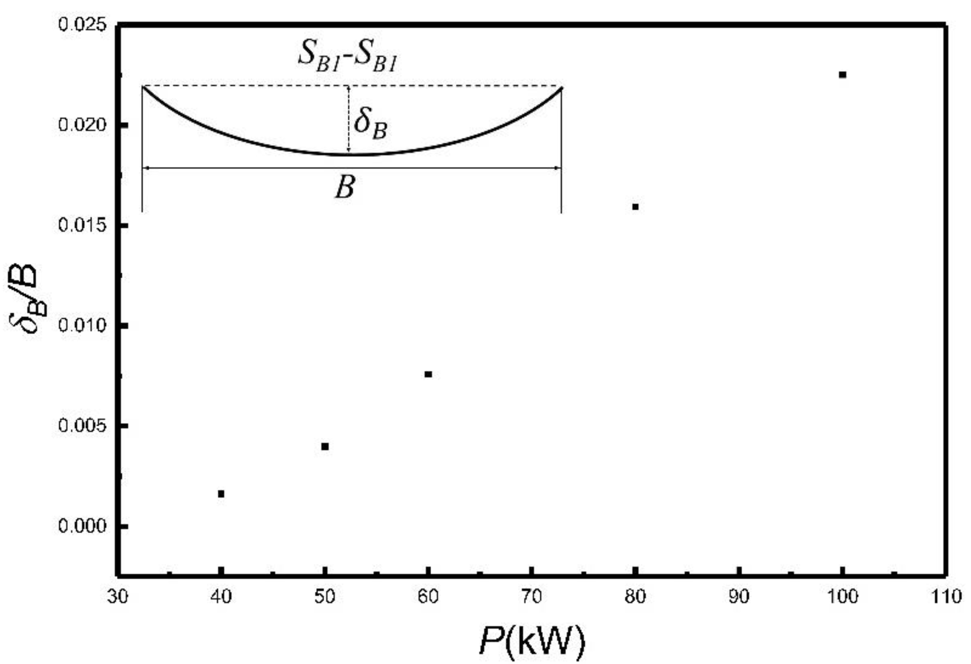
The previous results show that increasing the coil width can produce a larger curvature. However, a wider coil could be unfavorable to produce shapes with smaller curvatures. In this study, the coil input power is changed to calculate and investigate the curvature coverage of a wider coil. The calculation is based on the coil used in Case 3. The plate deformation and curvature distribution under heating conditions with different input powers P are calculated, and the results are shown in Figure 15 and Figure 16.
Figure 15 and Figure 16 show that for a wider coil, changing the input power can produce deflection and curvature on a corresponding scale. For ship hull plates, the formation range of a wider coil satisfies the actual processing requirements.
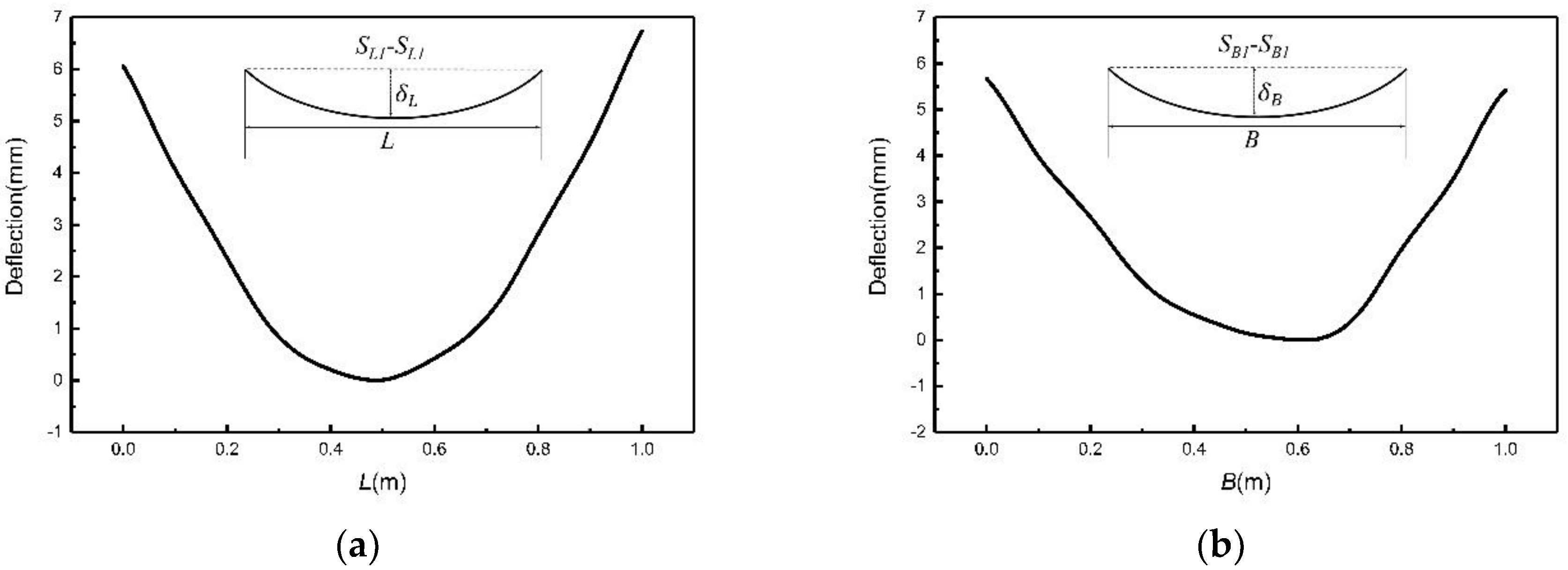
In the test and previous calculation, the formed plates are mainly saddle-type. In order to verify the ability of a wider coil in forming other types, the heating patterns shown in Figure 17 are calculated and the highest temperature during heating is 700 °C. The deflection of the formed plate is shown in Figure 18. It can be seen from Figure 16 and Figure 18 that a wider coil can form different curvatures and different types of a ship hull plate. This means that the capacity of the wider coil can meet the processing needs of the ship hull plates.
3.3. Efficiency Comparison of Different Coil Widths
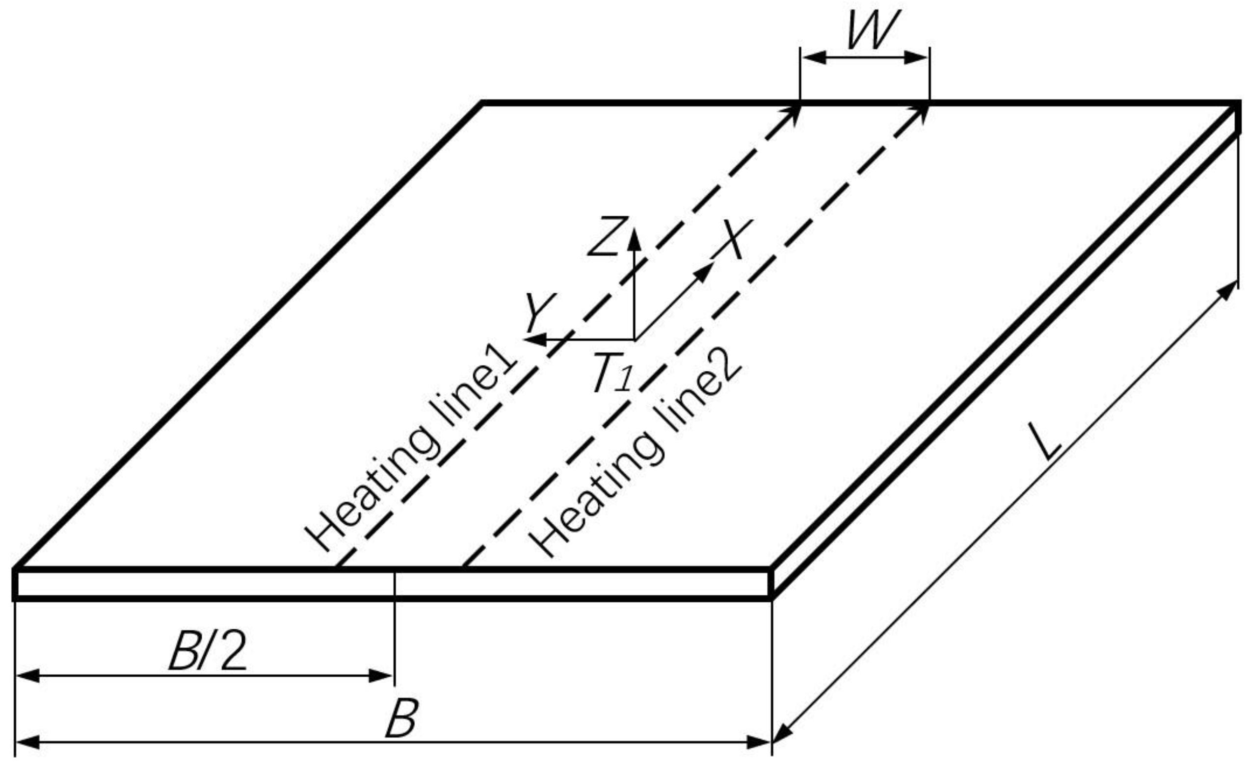
In the following section, a forming deformation shape of the plate is selected to investigate the influence of the heating time with different coil widths. The calculations are based on the parallel heating of the coil in Case 5 (a narrower coil) along the plate’s L direction as shown in Figure 19 and the single-pass heating of the coil in Case 3 (a wider coil) as shown in Figure 4. The two forming deformation shapes are then compared in order to study the forming shape and processing efficiency. In Case 5, the distance between the heating lines is W = 0.05 m. In both calculations, the highest temperature at the plate’s heating line is fixed at 700 °C and the travel speeds at all heating lines are equal.
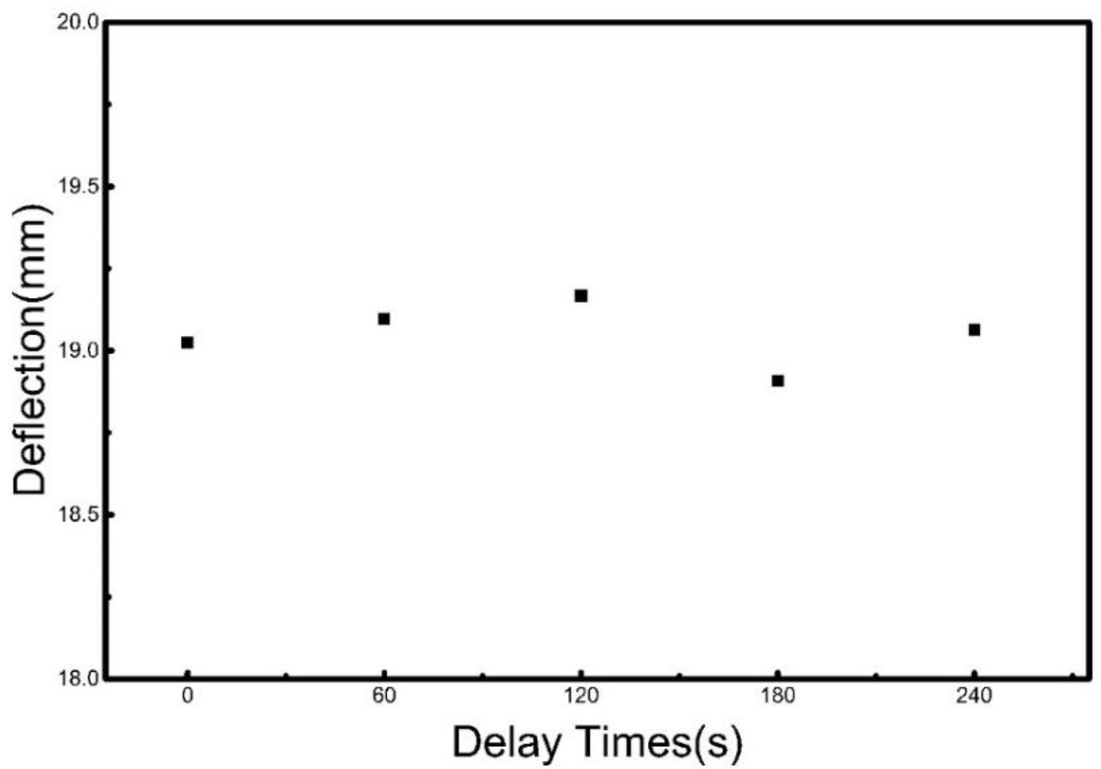
Considering the interval between the heating processes in Case 5, i.e., when the plate is heated for a second time, the residual temperature could affect the final plate deformation shape. This also makes it difficult to compare the heating deformation time for Case 5 with that of Case 3. For parallel heating, different intervals are applied to the two heating lines for calculation; i.e., after the first heating line is completed, different intervals are applied before the second heating.
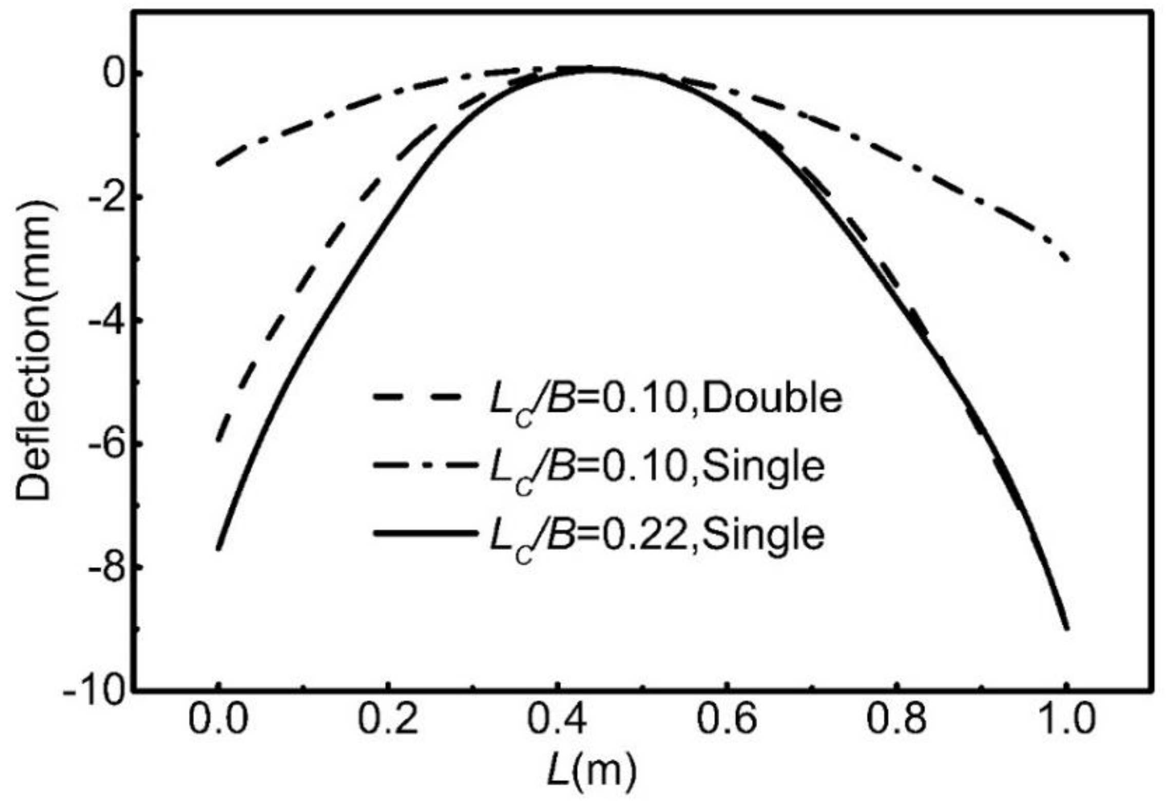
Figure 20 shows the final deflection at the plate B direction center for two heating lines subjected to parallel heating with different intervals. It shows that in parallel heating, the interval between the heating lines has an insignificant impact on the plate heating deformation. Hence, compared with heating completion time for Case 3, the parallel heating interval for Case 5 is zero in theory. This means that the processing time for Case 5 is twice that for Case 3. When the single-pass heating for Case 3 and the two-pass heating for Case 5 have the same travel speed and the same maximum temperature, the calculation results are as shown in Figure 21 and Figure 22.
Figure 21 and Figure 22 show comparisons of the deformation shapes at the plate transversal and longitudinal flexure lines of center sections. For the transversal and longitudinal deformation shapes of the plate, Case 5 requires two-pass heating to achieve the same plate deformation shape as single-pass heating for Case 3, which means a higher forming processing efficiency for Case 3.
Based on the above calculation results, a moderate increase in coil width essentially increases the plate heating range and the local contraction force, which is favorable to increasing the deformation level of the processed plate. During heating, when the coil travel speed is fixed and for a specific plate shape, a wider coil requires less heating time than a narrower coil does. This means that a wider coil has a higher forming efficiency than a narrower one. Additionally, as the maximum temperature cannot increase infinitely, for a wider coil, the input power can be reduced to cover a narrower coil to produce a small deformation or small curvature. However, because an increase in power input results in a further increase in temperature, when the maximum temperature is constrained, it is difficult for a narrower coil to achieve a large deformation or a large curvature produced by a wider coil by increasing the input power of a narrower coil.
It is worth noting that an excessively wide coil could change the localized heating condition and reduce the local deformation of the heated plate. Therefore, the coil dimension selection should be optimized.
As a fundamental study, the calculations in this paper are focused on single-pass or two-pass heating lines. However, multiple heating lines, heating lines in different directions or different plate deformation shapes will not change the previous conclusions.
4. Conclusions
In this study, the temperature field and deformation field of a plate subjected to an electromagnetic induction heating are calculated and compared via the finite element method and testing. After the applicability of the finite element method is validated, the effect of induction coil dimension variation on plate heating deformation is investigated via numerical simulation. The following conclusions are obtained:
1. The test shows that the finite element method can accurately calculate the temperature field and deformation field of a plate subjected to induction heating.
2. The heating-induced deflection and curvature increase with coil size increase. This is beneficial for improving the efficiency of line heating forming. Besides, a wider coil can produce a plate shape that is attainable by a narrower coil.
3. For a specific plate shape, a wider coil requires less heating time than a narrower coil does. A moderate increase in coil width improves the processing efficiency of line heating forming.
4. An excessively wide coil could change the localized heating condition and thus reduce the local deformation of the heated plate. Because the coil dimension is closely related to the forming efficiency, in actual processing, the coil dimension and input condition should be optimized based on the loading capability and the forming requirement to improve the forming efficiency.
Author Contributions
Y.Z. designed the experiments’ plans, contributed to the discussions and reviewed the paper; H.D. carried out the experiments, performed the numerical simulations and wrote the paper; H.Y. assisted in the experiment and reviewed the paper.
Funding
This work was supported by the Ministry of Science and Technology of the People’s Republic of China (Grant No.: 2012DFR80390).
Conflicts of Interest
The authors declare no conflicts of interest.
References
- Ueda, Y.; Murakawa, H.; Rashwan, A.M.; Okumoto, Y.; Kamichika, R. Development of Computer Aided Process Planning System for Plate Bending by Line Heating (Report I): Relation between the Final Form of Plate and the Inherent Strain. Trans. JWRI 1991, 20, 275–285. [Google Scholar]
- Ueda, Y.; Murakawa, H.; Rashwan, A.M.; Okumoto, Y.; Kamichika, R.; Ishiyama, M.; Ogawa, J. Development of Computer Aided Process Planning System for Plate Bending by Line Heating (Report IV): Decision Making on Heating Conditions, Location and Direction. Trans. JWRI 1993, 22, 305–313. [Google Scholar]
- Yoshihiko, T.; Morinobu, I.; Hiroyuki, S. “IHIMU-α” a fully automated steel plate bending system for shipbuilding. J. IHI Technol. 2011, 51, 24–29. [Google Scholar]
- Bae, K.Y.; Yang, Y.S.; Hyun, C.M.; Cho, S.H. Derivation of simplified formulas to predict deformations of plate in steel forming process with induction heating. Int. J. Mach. Tools Manuf. 2008, 48, 1646–1652. [Google Scholar] [CrossRef]
- Boadi, A.; Tsuchida, Y.; Todaka, T.; Enokizono, M. Designing of suitable construction of high-frequency induction heating coil by using finite-element method. IEEE Trans. Magn. 2005, 41, 4048–4050. [Google Scholar] [CrossRef]
- Pan, Z. Numerical Simulation of Induction Heating Based on ANSYS and the Design of Inductor. Master’s Thesis, Dalian University of Technology, Dalian, China, December 2006. [Google Scholar]
- Lee, K.S.; Hwang, B. An approach to triangular induction heating in final precision forming of thick steel plates. J. Mater. Process. Technol. 2014, 214, 1008–1017. [Google Scholar] [CrossRef]
- Lee, J.S.; Lee, S.H. A study on the thermal deformation characteristics of steel plates due to multi-line heating. Int. J. Nav. Architect. Ocean. Eng. 2018, 10, 48–59. [Google Scholar] [CrossRef]
- Hu, X.; Liu, Y.; Zhang, X.; Deng, Y. Study on Parameters of the Inductor in High Efficiency Induction Heating for Plate Forming. Shipbuild. China 2009, 50, 101–108. [Google Scholar]
- Liu, Z.; Pan, J.; Yin, Y.; Huang, R. Effect of induction heating coil parameters on the temperature field of the tested subjects. Mech. Electr. Eng. Mag. 2015, 32, 317–323. [Google Scholar]
- Wang, Y.; Liu, C.; Wang, X. Influence of induction coil parameter on temperature field of steel plate and choosing of coil size. Heat Treat. Met. 2016, 41, 178–182. [Google Scholar]
- Sadeghipour, K.; Dopkin, J.A.; Li, K. A computer aided finite element/experimental analysis of induction heating process of steel. Comput. Ind. 1996, 28, 195–205. [Google Scholar] [CrossRef]
- Li, Y. Steel Structure Welding Residual Stress Analysis. Master’s Thesis, Wuhan University of Technology, Wuhan, China, April 2007. [Google Scholar]
Figure 1.
Overall calculation process of the induction heating.
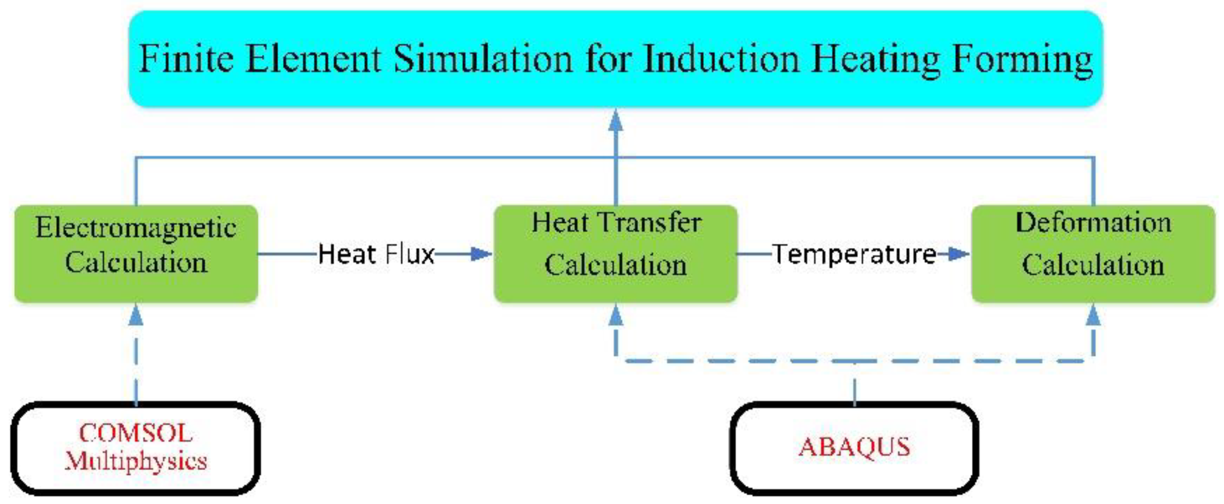
Figure 2.
Shape and dimension of the induction coil: (a) coil model; (b) coil image; (c) coil dimension and (d) tubular dimension of the coil.
Figure 2.
Shape and dimension of the induction coil: (a) coil model; (b) coil image; (c) coil dimension and (d) tubular dimension of the coil.
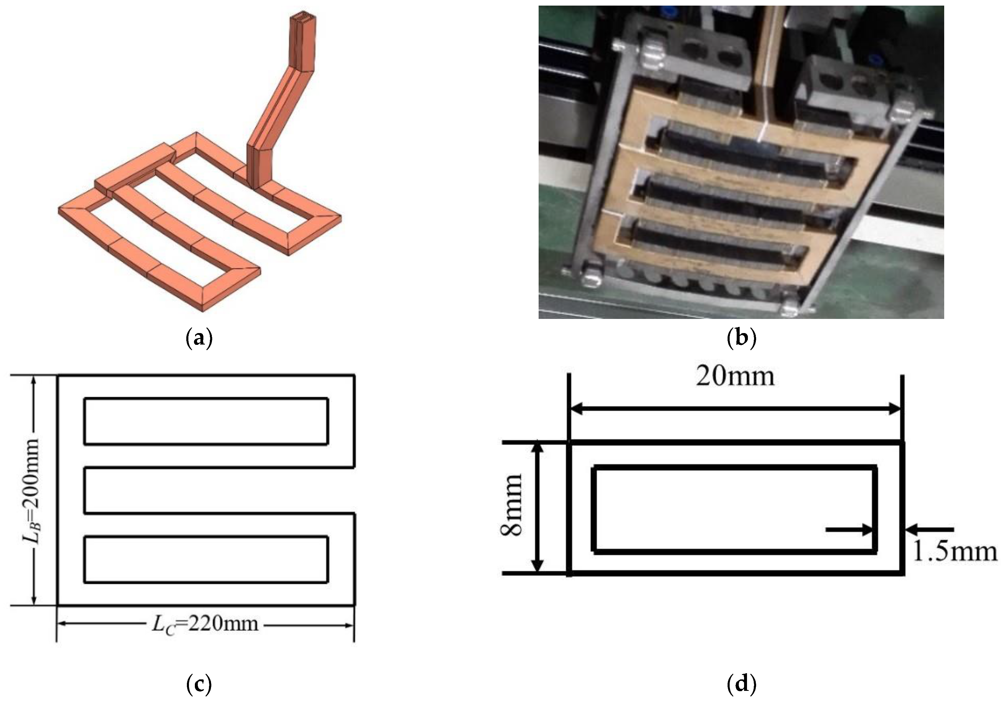
Figure 3.
Plate heating test using an induction coil.

Figure 4.
Induction coil heating deformation analysis of the experiment: (a) local heating contraction force and (b) effect of the resultant force of contractions along the L direction.
Figure 4.
Induction coil heating deformation analysis of the experiment: (a) local heating contraction force and (b) effect of the resultant force of contractions along the L direction.
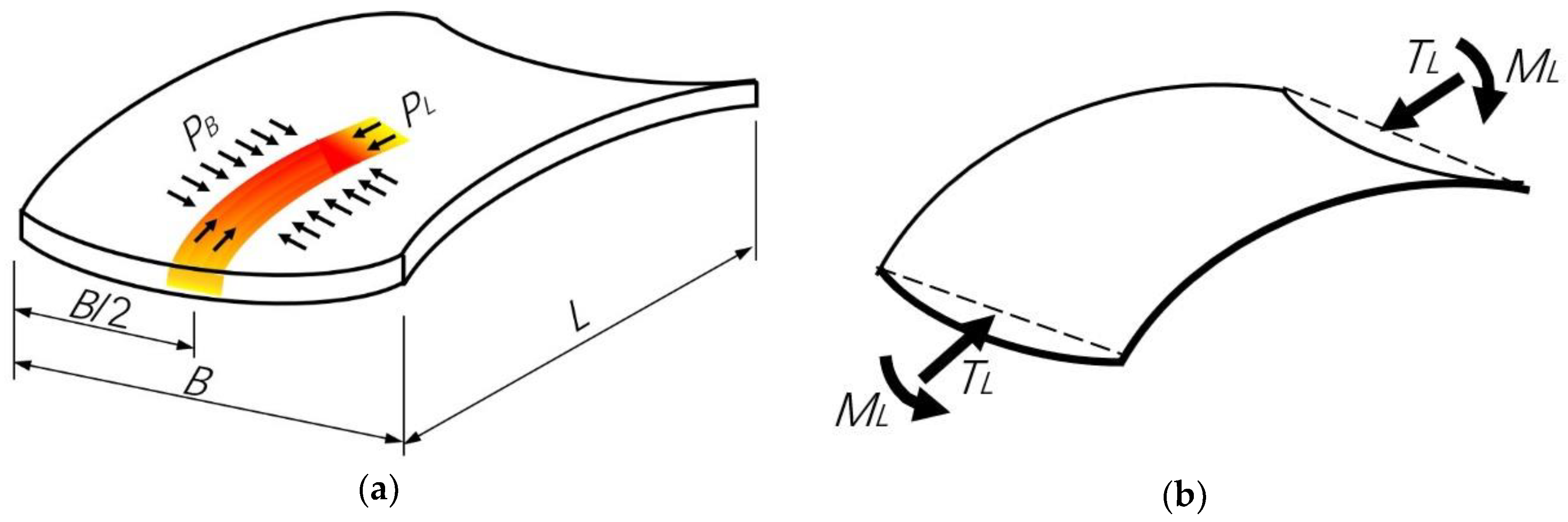
Figure 5.
Point and sections for comparing the finite element calculation results with the test results.
Figure 5.
Point and sections for comparing the finite element calculation results with the test results.

Figure 6.
Comparison of temperature history at T1. Finite Element Method (FEM), Exponential (EXP).
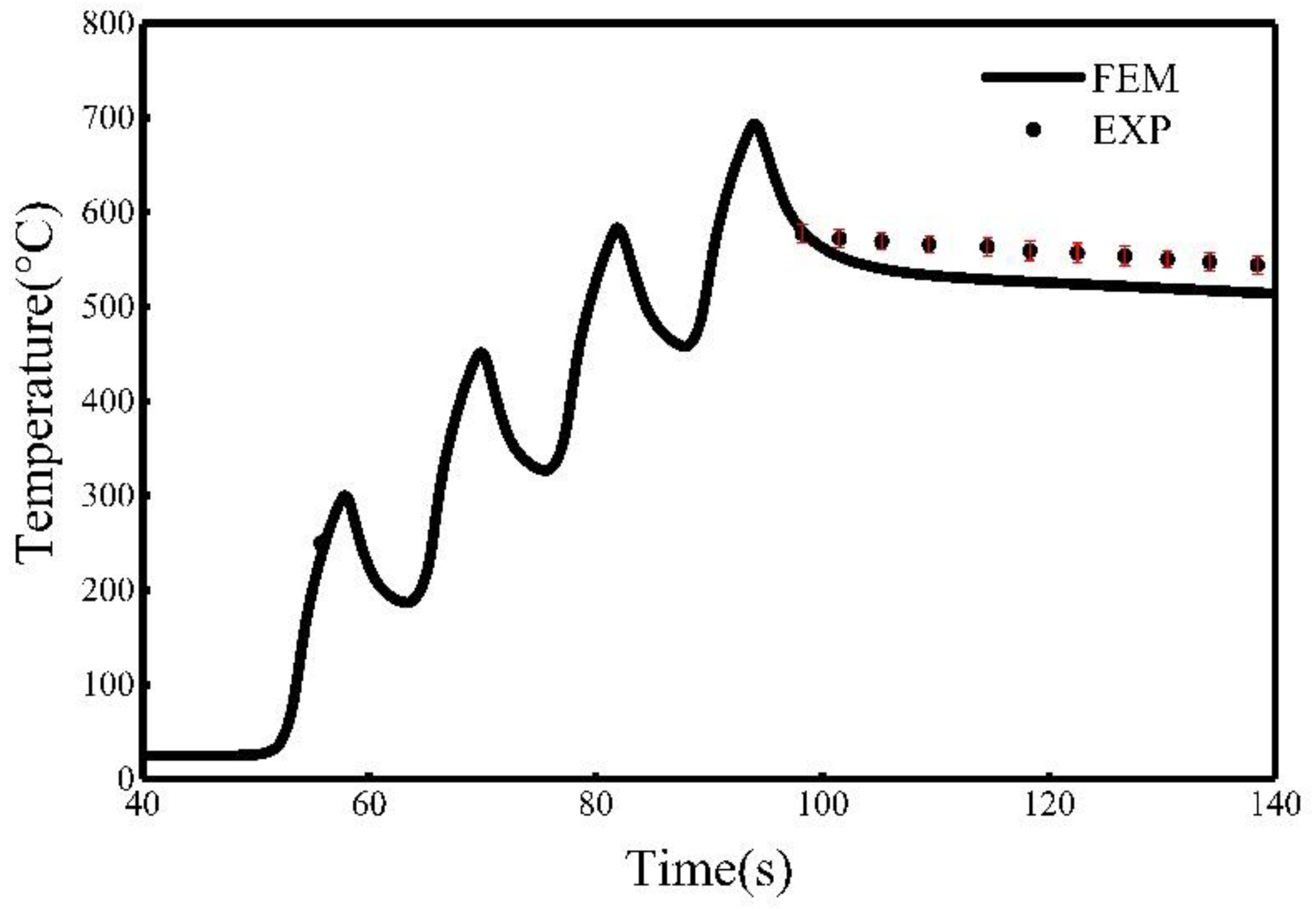
Figure 7.
Comparison of temperature at the induction coil heating line SL1-SL1.
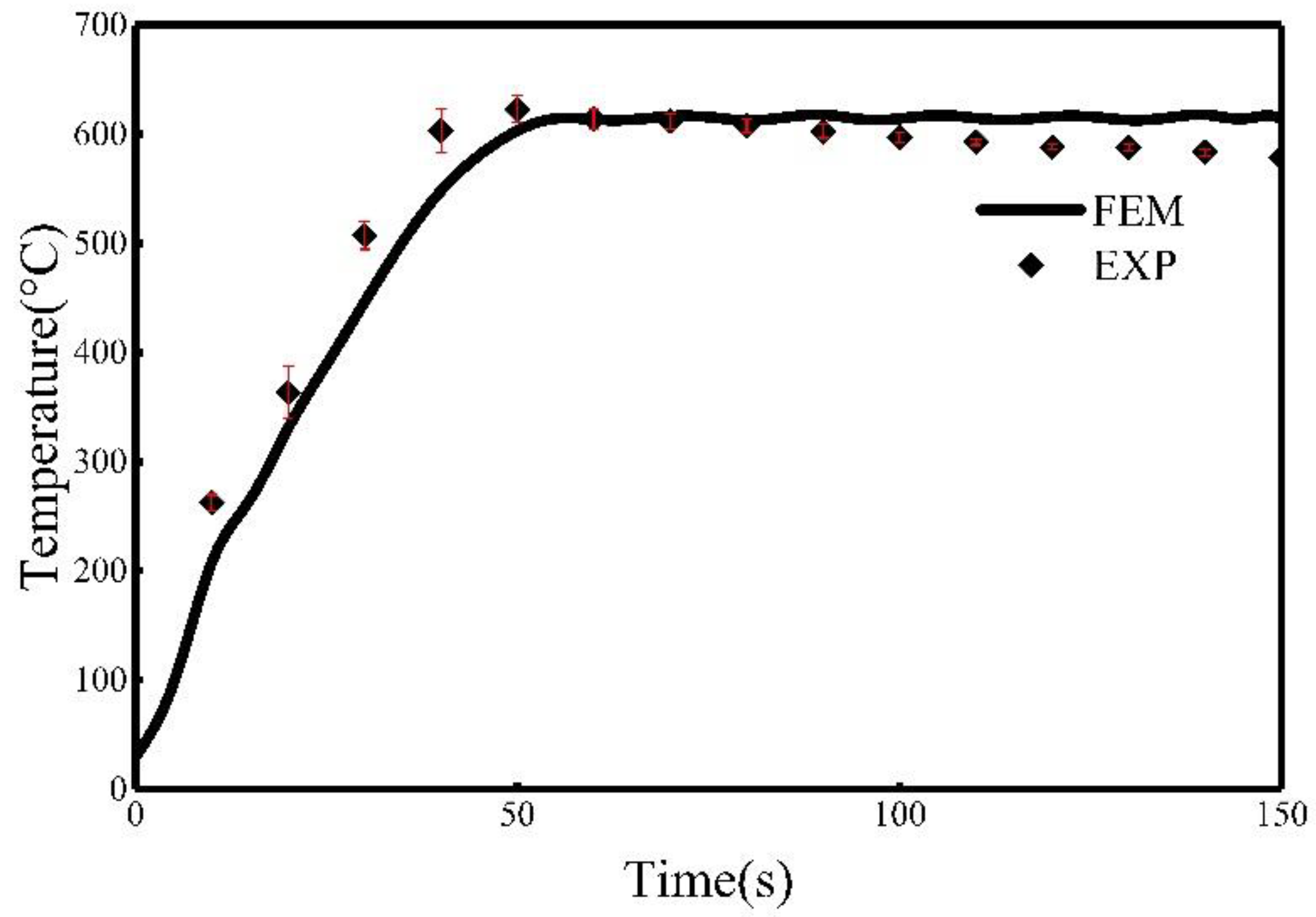
Figure 8.
Heat distribution in the finite element model of heat transmission after 115 s.

Figure 9.
Plate deformation from the test and the finite element calculation: (a) test deformation and (b) calculated deformation.
Figure 9.
Plate deformation from the test and the finite element calculation: (a) test deformation and (b) calculated deformation.

Figure 10.
Comparison of plate transversal bending deformation.

Figure 11.
Comparison of plate longitudinal bending deformation.
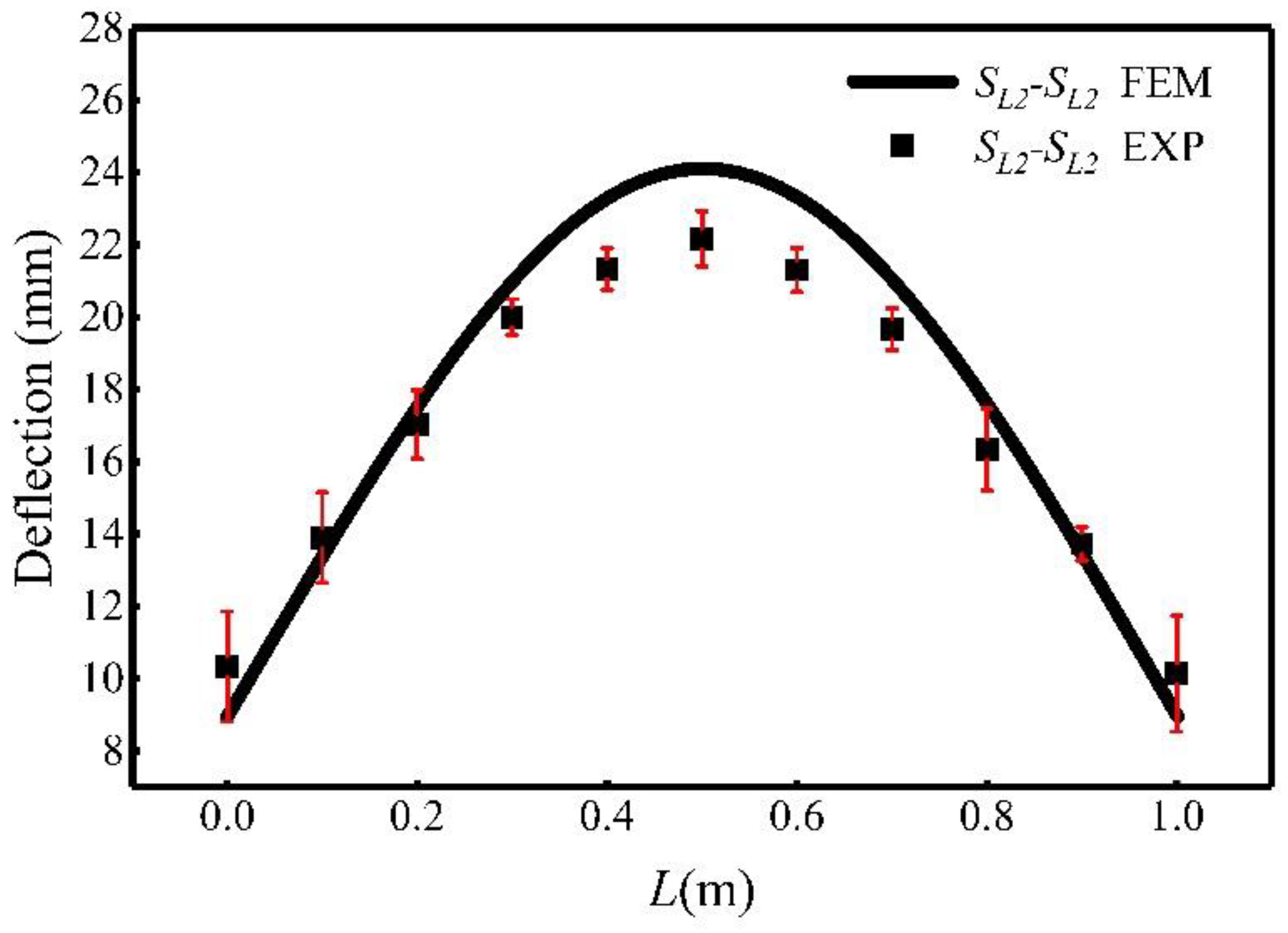
Figure 12.
Effect of coil width on the transversal bending deflection.
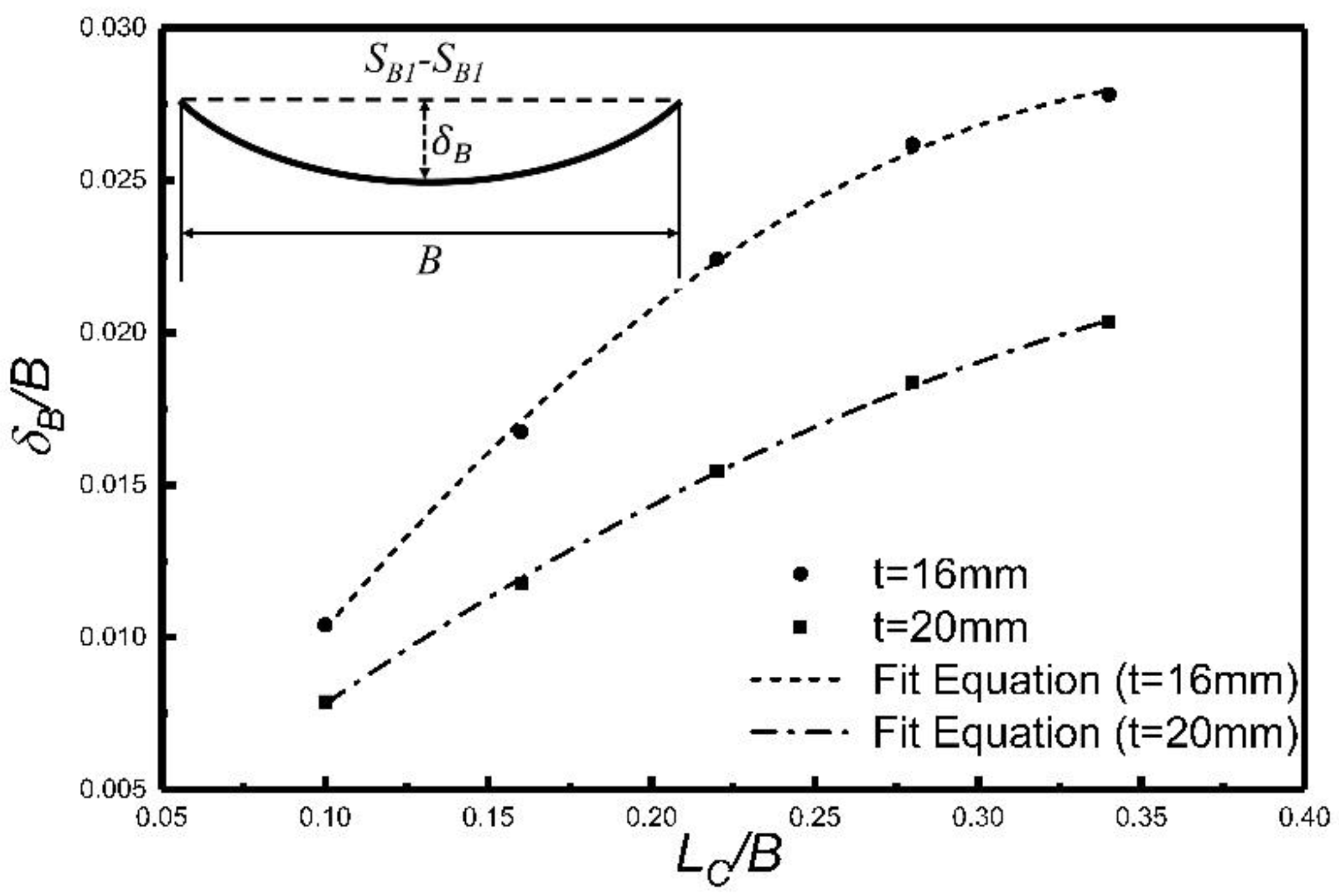
Figure 13.
Effect of coil width on the longitudinal bending deflection.

Figure 14.
Effect of coil width on transversal curvature.
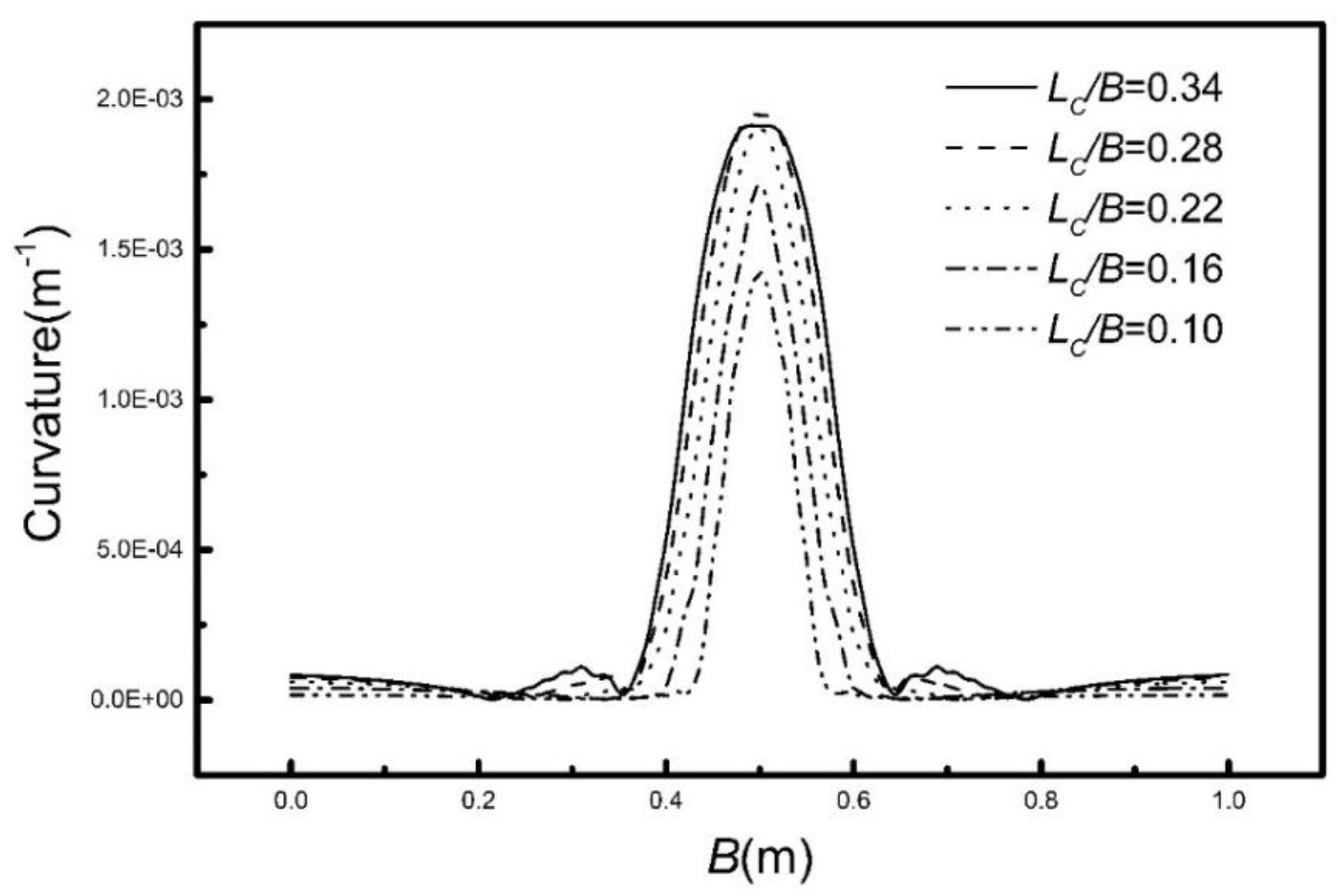
Figure 15.
Bending deflection of the SB1-SB1 section for different input powers.

Figure 16.
Transversal curvatures for different input powers.
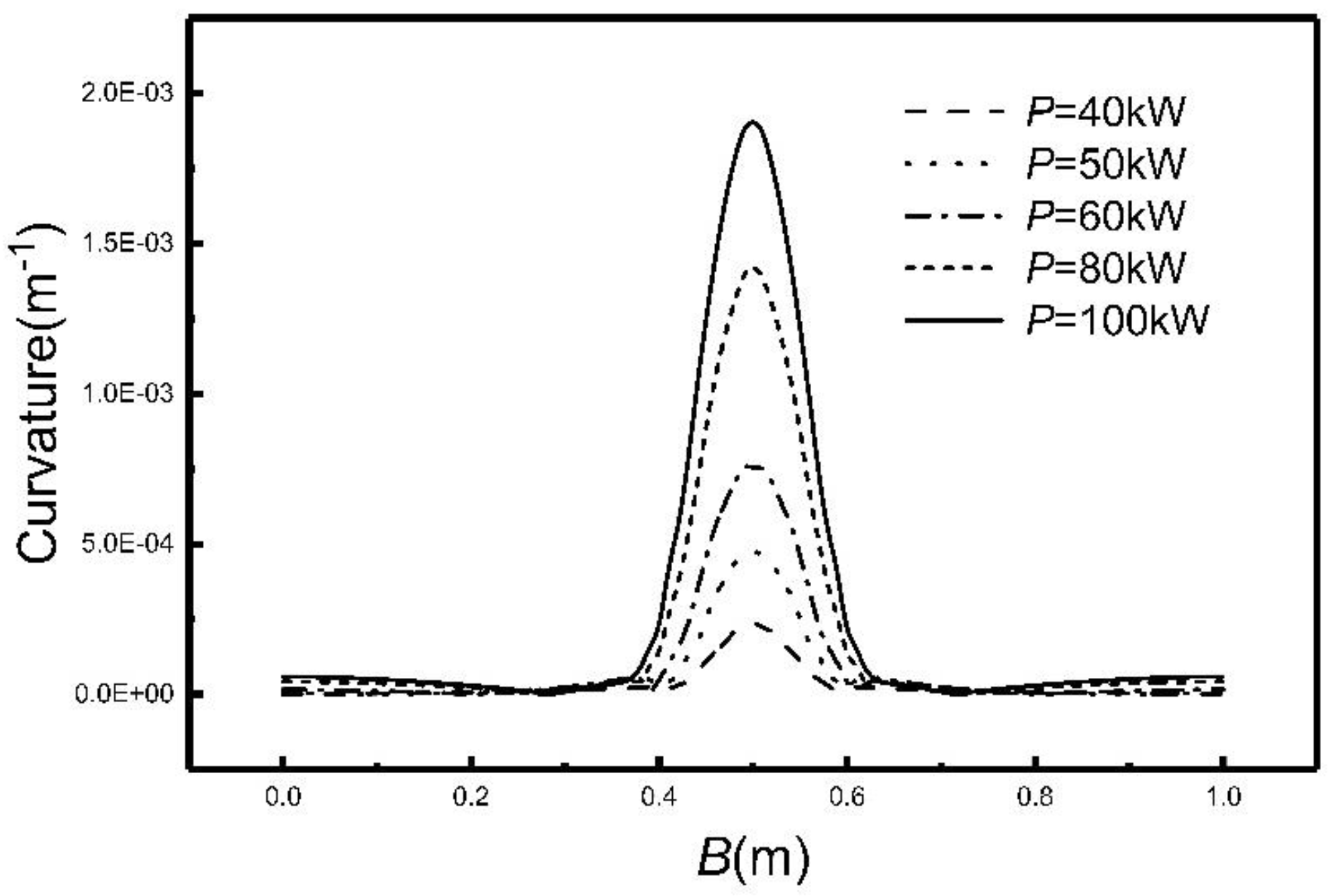
Figure 17.
Heating lines used for pillow-type plates.

Figure 18.
Deflection of a formed pillow-type plate: (a) deflection of the SL1-SL1 and (b) deflection of the SB1-SB1.
Figure 18.
Deflection of a formed pillow-type plate: (a) deflection of the SL1-SL1 and (b) deflection of the SB1-SB1.

Figure 19.
Parallel heating diagram (LC/B = 0.10).

Figure 20.
Maximum bending deflection of the SB1-SB1 section for various intervals.

Figure 21.
SB1-SB1 section flexure lines for different heating conditions.
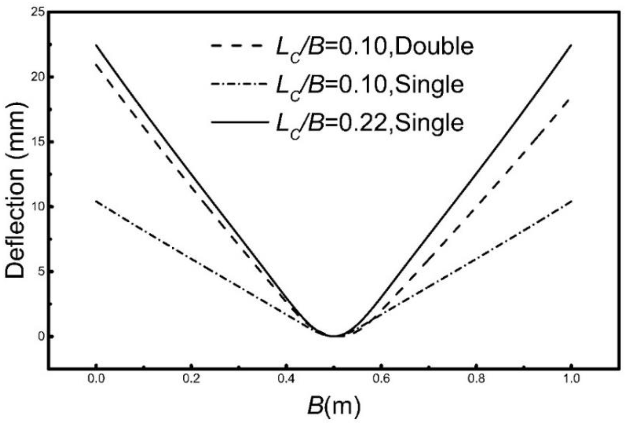
Figure 22.
SL1-SL1 section flexure lines for different heating conditions.


Table 1.
Thermal parameters of low carbon steel.
| Temperature (°C) | Density (kg/m3) | Specific Heat (J/(kg·°C)) | Heat Conductivity Coefficient (W/(m·°C)) |
|---|---|---|---|
| 0 | 7842 | 450.36 | 66.97 |
| 50 | - | 464.6 | 65.21 |
| 200 | 7822 | 498.1 | 57.38 |
| 250 | - | 502.26 | 54.91 |
| 300 | - | 514.82 | 53 |
| 400 | 7802 | 537.42 | 47.92 |
| 450 | - | 623.64 | 45.83 |
| 500 | - | 707.35 | 43.53 |
| 600 | 7782 | 812 | 39.3 |
| 650 | - | 904.07 | 36.37 |
| 700 | - | 967.69 | 34.74 |
| 800 | 7761 | 1026.32 | 31.02 |
Table 2.
Mechanical parameters of low carbon steel.
| Temperature (°C) | Young‘s Modulus (GPa) | Poisson Ratio | Heat Expansion Coefficient (1/°C) | Yield Strength (MPa) |
|---|---|---|---|---|
| 0 | 206 | 0.267 | 1.20 × 10⁻⁵ | 235 |
| 50 | 196 | 0.29 | 1.25 × 10⁻⁵ | - |
| 200 | 196 | 0.322 | 1.40 × 10⁻⁵ | 163 |
| 250 | 186 | 0.296 | 1.43 × 10⁻⁵ | - |
| 300 | 186 | 0.262 | 1.47 × 10⁻⁵ | - |
| 400 | 166 | 0.24 | 1.54 × 10⁻⁵ | 130 |
| 450 | 157 | 0.229 | 1.57 × 10⁻⁵ | - |
| 500 | 157 | 0.223 | 1.59 × 10⁻⁵ | - |
| 600 | 135 | 0.223 | 1.64 × 10⁻⁵ | 119 |
| 650 | 117 | 0.223 | 1.66 × 10⁻⁵ | - |
| 700 | 112 | 0.223 | 1.67 × 10⁻⁵ | - |
| 800 | 113 | 0.223 | 1.69 × 10⁻⁵ | 109 |
Table 3.
Calculation schemes.
| Coil Speed | Highest Temperature | ||||
|---|---|---|---|---|---|
| 10 mm/s | 700 °C | ||||
| Calculation Schemes | |||||
| Case 1 | Case 2 | Case 3 | Case 4 | Case 5 | |
| LC/B = 0.34 | LC/B = 0.28 | LC/B = 0.22 | LC/B = 0.16 | LC/B = 0.10 | |
© 2018 by the authors. Licensee MDPI, Basel, Switzerland. This article is an open access article distributed under the terms and conditions of the Creative Commons Attribution (CC BY) license (http://creativecommons.org/licenses/by/4.0/).
Share and Cite
MDPI and ACS Style
Dong, H.; Zhao, Y.; Yuan, H. Effect of Coil Width on Deformed Shape and Processing Efficiency during Ship Hull Forming by Induction Heating. Appl. Sci. 2018, 8, 1585. https://doi.org/10.3390/app8091585
AMA Style
Dong H, Zhao Y, Yuan H. Effect of Coil Width on Deformed Shape and Processing Efficiency during Ship Hull Forming by Induction Heating. Applied Sciences. 2018; 8(9):1585. https://doi.org/10.3390/app8091585
Chicago/Turabian StyleDong, Hongbao, Yao Zhao, and Hua Yuan. 2018. "Effect of Coil Width on Deformed Shape and Processing Efficiency during Ship Hull Forming by Induction Heating" Applied Sciences 8, no. 9: 1585. https://doi.org/10.3390/app8091585
Note that from the first issue of 2016, this journal uses article numbers instead of page numbers. See further details here.