Review

Diagnostics and Dosimetry Solutions for Multidisciplinary Applications at the ELIMAIA Beamline

by
Valentina Scuderi
1,2,*,
Antonino Amato
2,
Antonio Giuseppe Amico
2,
Marco Borghesi
3,
Giuseppe Antonio Pablo Cirrone
2,
Giacomo Cuttone
2,
Antonin Fajstavr
1,
Lorenzo Giuffrida
1,
Filip Grepl
1,
Georg Korn
1,
Giuseppina Larosa
2,
Renata Leanza
2,
Daniele Margarone
1,
Giuliana Milluzzo
2,3,
Giada Petringa
2,
Jan Pipek
2,
Antonio Russo
2,
Francesco Schillaci
1,
Andriy Velyhan
1 and
Francesco Romano
2,4
1
Institute of Physics ASCR, v.v.i. (FZU), ELI-Beamlines Project, 18221 Prague, Czech Republic
2
Istituto Nazionale di Fisica Nucleare, Laboratori Nazionali del Sud, 95123 Catania, Italy
3
Centre for Plasma Physics, School of Mathematics and Physics, Queen’s University Belfast, Belfast BT7 1NN, UK
4
National Physical Laboratory, CMES Medical Radiation Science, Teddington TW110LW, UK
*
Author to whom correspondence should be addressed.
Appl. Sci. 2018, 8(9), 1415; https://doi.org/10.3390/app8091415
Submission received: 7 July 2018 / Revised: 6 August 2018 / Accepted: 13 August 2018 / Published: 21 August 2018
(This article belongs to the Special Issue Laser-Driven Particle Acceleration)

Abstract

:
ELI (Extreme Light Infrastructure) multidisciplinary applications of laser-ion acceleration (ELIMAIA) is one the user facilities beamlines of the ELI-Beamlines facility in Prague. It will be dedicated to the transport of laser-driven ion beams and equipped with detectors for diagnostics and dosimetry, in order to carry out experiments for a broad range of multidisciplinary applications. One of the aims of the beamline is also to demonstrate the feasibility of these peculiar beams for possible medical applications, which means delivering controllable and stable beams, properly monitoring their transport parameters and accurately measuring the dose per shot. To fulfil this task, innovative systems of charged particle beam diagnostics have been realized and alternative approaches for relative and absolute dosimetry have been proposed. Concerning the first one, real-time diagnostic solutions have been adopted, involving the use of time-of-flight techniques and Thomson parabola spectrometry for an on-line characterization of the ion beam parameters, as well as radiochromic films, nuclear track detectors (typically CR39), and image plates for single shot measurements. For beam dosimetry, real-time beam/dose monitoring detectors have been realized, like the secondary emission monitor and a double-gap ionization chamber, which can be cross calibrated against a Faraday cup, used for absolute dosimetry. The main features of these detectors are reported in this work together with a description of their working principle and some preliminary tests.

1. Introduction

Ion acceleration driven by high-intensity laser pulses is attracting an impressive and steadily increasing research effort. Experiments over the past two decades have demonstrated the generation of several tens of MeV proton and ion beams with unique properties, which have stimulated interest in many innovative applications. Efficient energy boost of the laser-accelerated ions is critical for their applications in biomedical and clinical research. Achievable proton energies continue to rise, with currently the highest energies of the order of hundred MeV, as recently reported in the literature [1], allowing access to the medical therapy energy window in protontherapy (60–250 MeV) [2].
Hadron therapy is currently considered one of the most advanced and precise external radiotherapy techniques for tumour treatment [3]. Hadrons show several advantages with respect to more conventional radiation sources, such as electrons, and gamma- and X-rays, in terms of both spatial precision of the released dose and biological effectiveness [4]. Nevertheless, current acceleration techniques for protons and ions demand high financial investments and running costs associated with large-scale accelerator facilities, ion beam delivery, and radiation shielding systems, thus preventing their widespread use in clinical application.
On the other hand, ion beams accelerated by high-intensity lasers are very promising because they are produced in an extremely compact “plasma accelerator” in comparison with conventional accelerators, thus having huge potential in terms of overall cost of a laser-based accelerator facility. Such particle beams are, typically, accelerated over micrometer range distances and have no limitation in terms of ion species, different to conventional accelerators. These characteristics make such an approach extremely appealing both for applications and for new basic science to be explored [5,6].
A more compact laser-based therapy unit could provide particle therapy to a much broader range of patients [7,8] and, moreover, would offer the advantage of an integrated system able to provide different types of radiations from the same source (laser) for different purposes: (i) performing treatments with different types of radiation sources (protons, heavier ions, electrons, X/gamma-rays, and neutrons) to explore new combined modalities; and (ii) coupling treatment and imaging for monitoring the tumour position without adding additional devices.
Recently a unique user beamline ELIMAIA (ELI (Extreme Light Infrastructure) multidisciplinary applications of laser-ion acceleration) [9] has been installed at the ELI-Beamlines international user facility (Czech Republic). Its main goal is to deliver laser driven proton/ion beams both for basic laser-plasma acceleration physics and for multidisciplinary user applications, especially in the field of hadron-therapy or biomedical research [10]. The ELIMAIA beamline has been designed and developed at the Institute of Physics of the Academy of Science of the Czech Republic (IoP-ASCR) in Prague and at the National Laboratories of Southern Italy of the National Institute for Nuclear Physics (LNS-INFN) in Catania (Italy).
ELIMAIA consists of two main subsystems: the ion acceleration platform and the ELIMED (ELI medical and multidisciplinary applications) user application line (ion beam transport and dosimetry). A 3D rendering of the ELIMAIA beamline (Ion Accelerator + ELIMED) is shown in Figure 1. A complete description of ELIMAIA, including ELIMED, is reported in the literature [9]. The ion acceleration platform consists of a double plasma mirror chamber; a local laser diagnostics station; and an interaction chamber providing laser beam transport, pulse treatment, ion source generation, and in-situ ion and plasma characterization. The ELIMED user application line will provide ion beam transport (permanent magnet quadrupoles, PMQs), energy selection (resistive dipole chicane system, ESS), ion diagnostics and shaping, online dosimetry, and in-air sample irradiation end-station for users to enable them to apply laser-driven ion beams in multidisciplinary fields [9,11].
Until now, most of the experiments on laser-driven proton acceleration have been performed in the so-called TNSA (target normal sheath acceleration) regime dominating for laser intensities from 1018 W/cm2 up to 1020 W/cm2 [12]. The availability of ultrahigh intensity lasers at ELI-Beamlines (>1022 W/cm2) will allow entering new ion acceleration regimes, such as RPA (radiation pressure acceleration) leading to significant progress towards the 100 MeV/u range.
Although various acceleration regimes and approaches to laser-plasma acceleration are being studied, both theoretically and experimentally, and will be investigated in the near future at ELIMAIA, such new compact proton/ion sources are not suitable for several multidisciplinary applications yet, especially if compared with the sources available at conventional accelerator facilities.
Laser and laser-target technology is experiencing rapid development to enhance the performance and to optimize the ion source in terms of higher ion energies, higher intensity, and beam collimation. Recent studies at different laser regimes have demonstrated that the use of nano-structures on the laser-irradiated surface of the target strongly enhances the maximum proton energy and the spatial quality of the beam [13,14]. Furthermore, the use of micro-structures on the target rear surface allows modulation and control of the proton beam spatial profile [15]. Cryogenic hydrogen targets seem to be very promising for acceleration of purely proton beams (no ion contaminants) at a high repetition rate and can be potentially used in future for a proton acceleration beamline based on high peak power (PW-class) lasers [16].
Nevertheless, such non-conventional ion sources still suffer from shot-to-shot fluctuations due to the non-linear nature of laser-generated plasma. The current limitation due to the instability of the beam could be overcome by an accurate shot-by-shot characterization and control of the laser accelerated particle beam. A real-time diagnosis coupled with new devices for accurate dose measurements of the laser-accelerated ions is crucial to monitor and to tune the ion source to deliver the required dose to the user samples. This is particularly relevant for the envisioned medical and biological applications.
However, the very different characteristics of laser-driven proton beams compared with conventional sources outperform capabilities of traditional particle detectors to measure ion energies and fluxes, thus requiring development of innovative detectors.
A detailed description of the technical solutions developed and tested for ad-hoc diagnostics systems and the dosimeters which are implemented into the ELIMAIA beamline will be presented in the following sections.

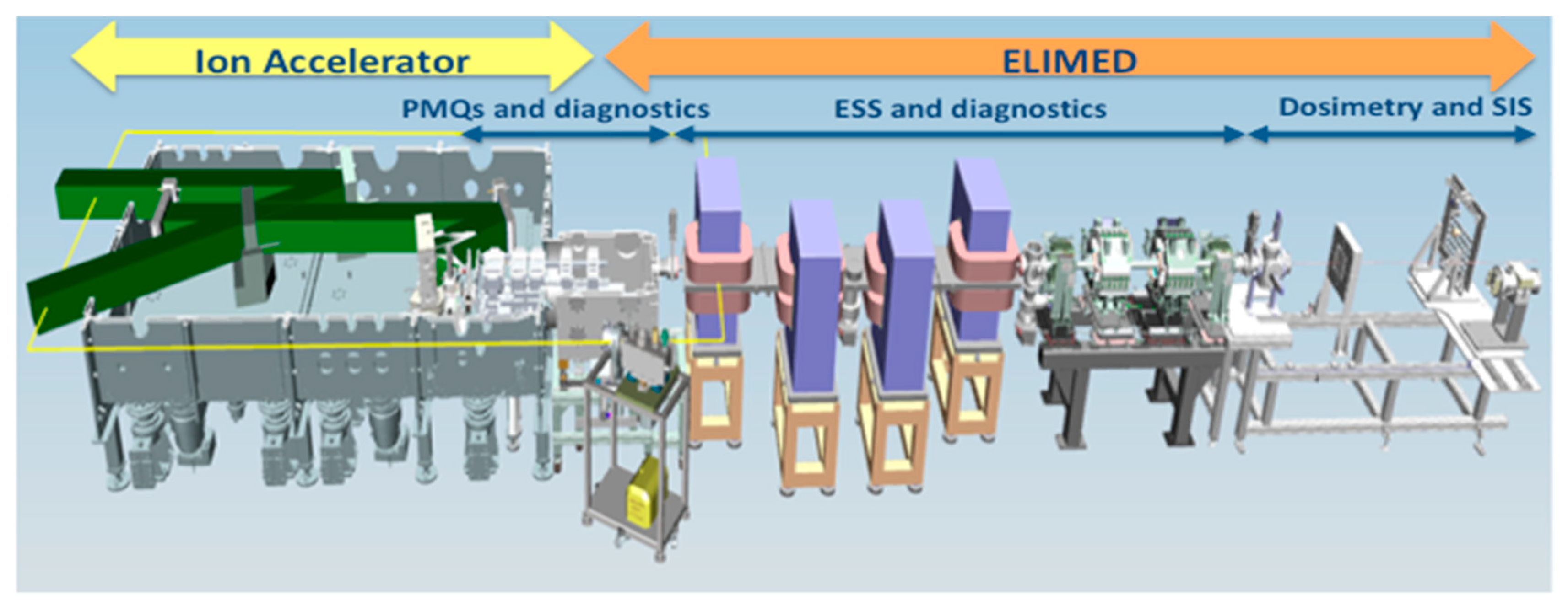
2. ELIMAIA Diagnostics

Considering the high laser repetition rate (1–10 Hz) at ELIMAIA, a robust real time particle bunch diagnosis will allow tuning laser parameters and optimizing proton/ion transport from the ELIMED focusing system through the energy selection in order to deliver a stable proton beam to users for a broad range of multidisciplinary applications of such non-conventional beams.
The main physical and technological issues in developing real-time robust diagnostics are mainly related to the following: high-pulse flux (1010–1012 ions/pulse), short bunch duration (0.1–1 ns close to the source), ultra-high pulse dose rate (up to 1012 Gy/min) compared with conventional clinical proton beams (107–1010 particles/s and dose-rate up to 10–50 Gy/min), high laser repetition rate (up to 10 Hz), limited shot to shot reproducibility of the ion beam parameters, and large electro-magnetic pulse (EMP) associated to high intensity laser-matter interaction, which can seriously affect the operation of standard electronics.
Technical solutions implemented into the ELIMAIA beamline are divided into two different categories:
  • real-time diagnostics based on Thomson parabola spectrometers (TPS) and detectors working in time-of-flight (TOF) providing an on line characterization of the ion beam features;
  • diagnostics operating in single shot mode using well-established detectors as radiochromic films (RCF), nuclear track detectors (typically CR39), image plates (IP), and other types of dosimeters.

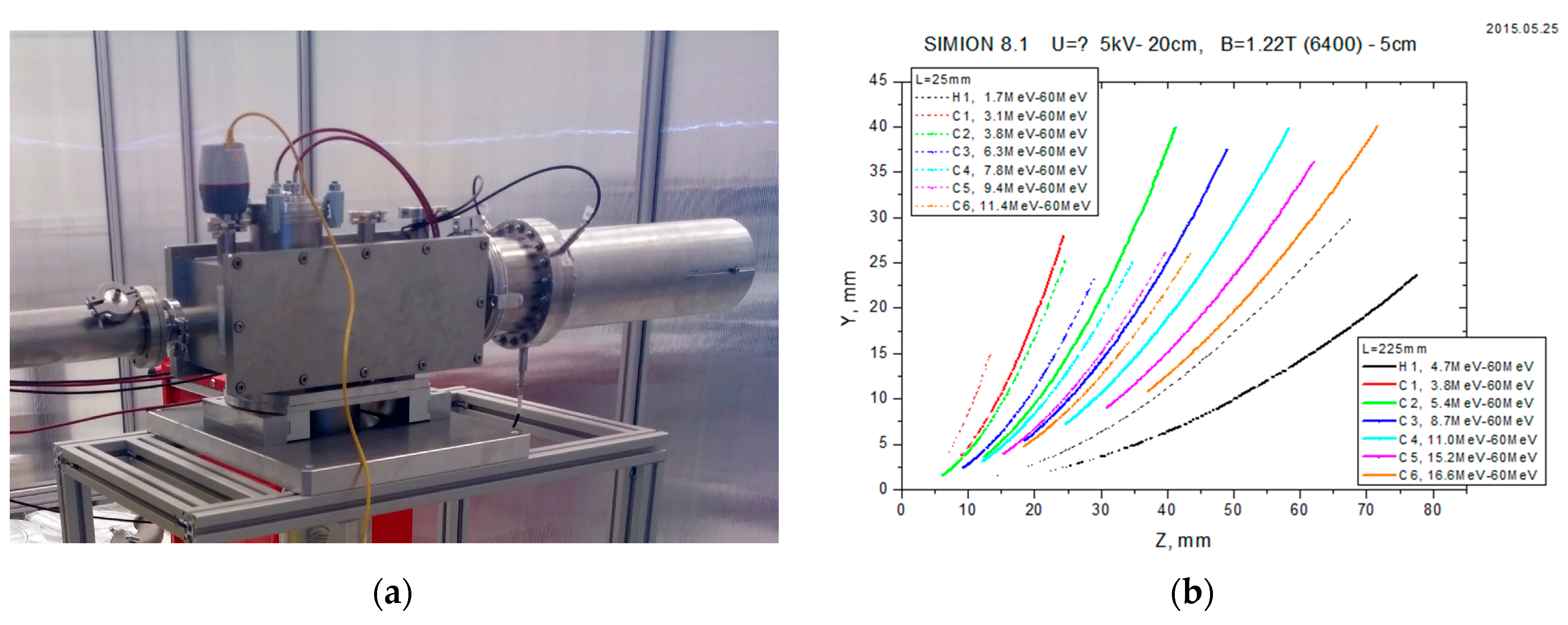
2.1. TPS: Thomson Parabola Spectrometer

Multi-species ion beams are inherently produced in the acceleration mechanism because of the chemical composition of the target bulk and/or the contamination layer covering the target (typically containing hydrocarbons and water vapour). Among standard ion diagnostics, which are commonly used, the TPS is arguably the most established diagnostics because of its unique capability to detect energy-resolved ion spectra while discriminating between species with different charge to mass ratio (Z/A) by means of the combined use of electric and magnetic fields. The ion beam, selected by the pinhole located at its entrance, travels through regions of parallel magnetic and electric fields applied transversely to the beam axis. Deflected ions are observed and amplified by means of a micro channel plate (MCP) and are sent to a phosphor screen enabling of producing image of energy-resolved ion spectra subsequently detected by a CCD camera. Acquisition of the image by the camera is controlled by a trigger signal from the laser.
The ELIMAIA TPS was designed, realized, and calibrated at ELI-Beamlines. Figure 2 shows a picture of the ELIMAIA TPS (Figure 2a). Ion trajectory simulations, using the particle accelerator tracking code SIMION [17], were perfomed to optimize TPS geometry and parameters and to investigate the energy resolution achievable.
Simulations of ions trajectories inside the ELIMAIA TPS for hydrogen and carbon ions of different charge states with energies up to 60 MeV/u for different pinhole-detection plane distances are shown in Figure 2a. Following increasing of TPS energy resolution is possible by an extension of the free flight distance of the system.
The diameter of the smallest of the two pinholes is set to be 200 μm. The permanent magnets are 5 cm in length, allowing reaching a magnetic field strength of about 1.2 T. The maximum voltage that can be applied on the 20 cm long electrodes is ±15 kV. The micro-channel plate with 77 mm of active diameter consists of a lead glass plate including an array of electron multipliers with diameter of the tube equals to 21 μm. The channel axes are biased by a small angle 6° to optimize the secondary electron emission in the channels. A double MCP with an aspect ratio of 40:1 amplifies the signal typically by a factor of more than 5 × 10⁶.
Figure 3 shows the configuration of the pinhole, magnetic, and electric electrodes together with the laser alignment system, the micro channel plate, and the high voltage power supplies.
The ELIMAIA TPS has its own pumping station (able to reach a vacuum level of 4 × 10⁻⁶ mbar) and a set of power supplies for feeding the electric field electrodes, the MCP electrodes and the phosphor screen by ±15 kV, −2 kV, and +5 kV, respectively. The alignment system allows adjusting the TPS in the horizontal plane in two transverse directions, and two rotational units help in pointing the system onto the target.

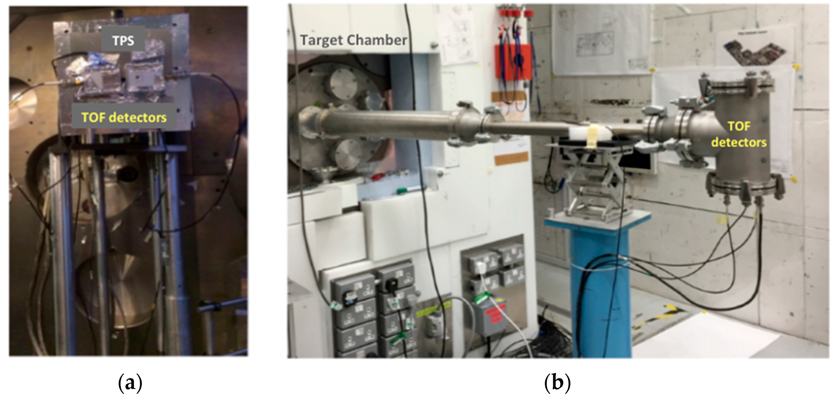
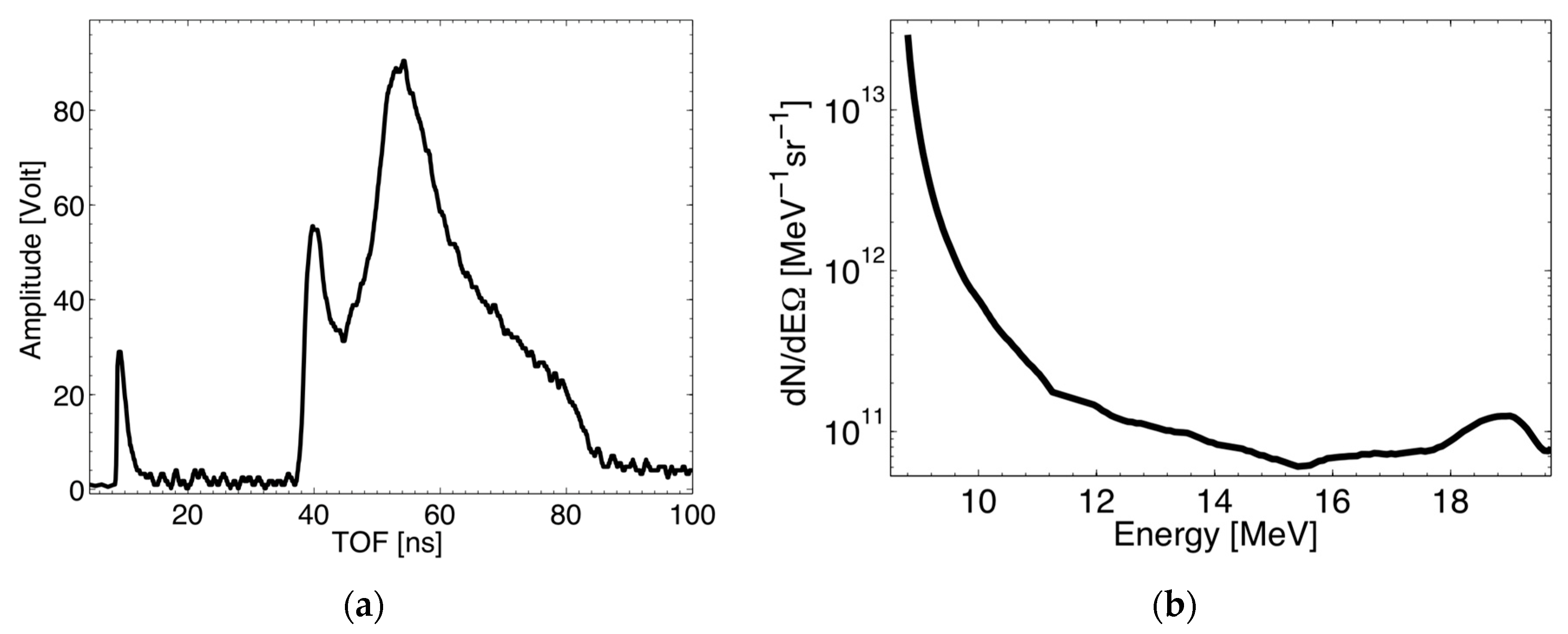
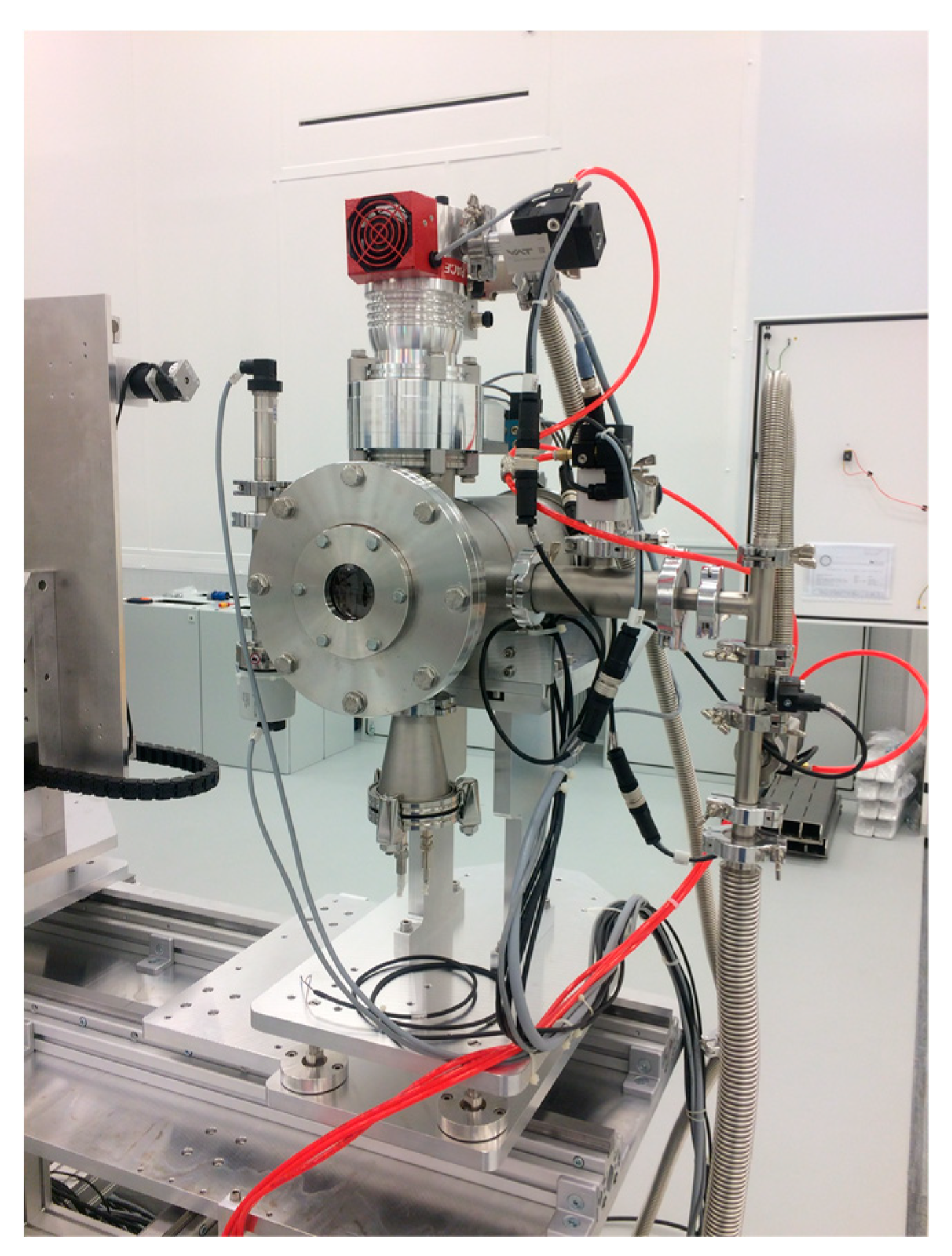
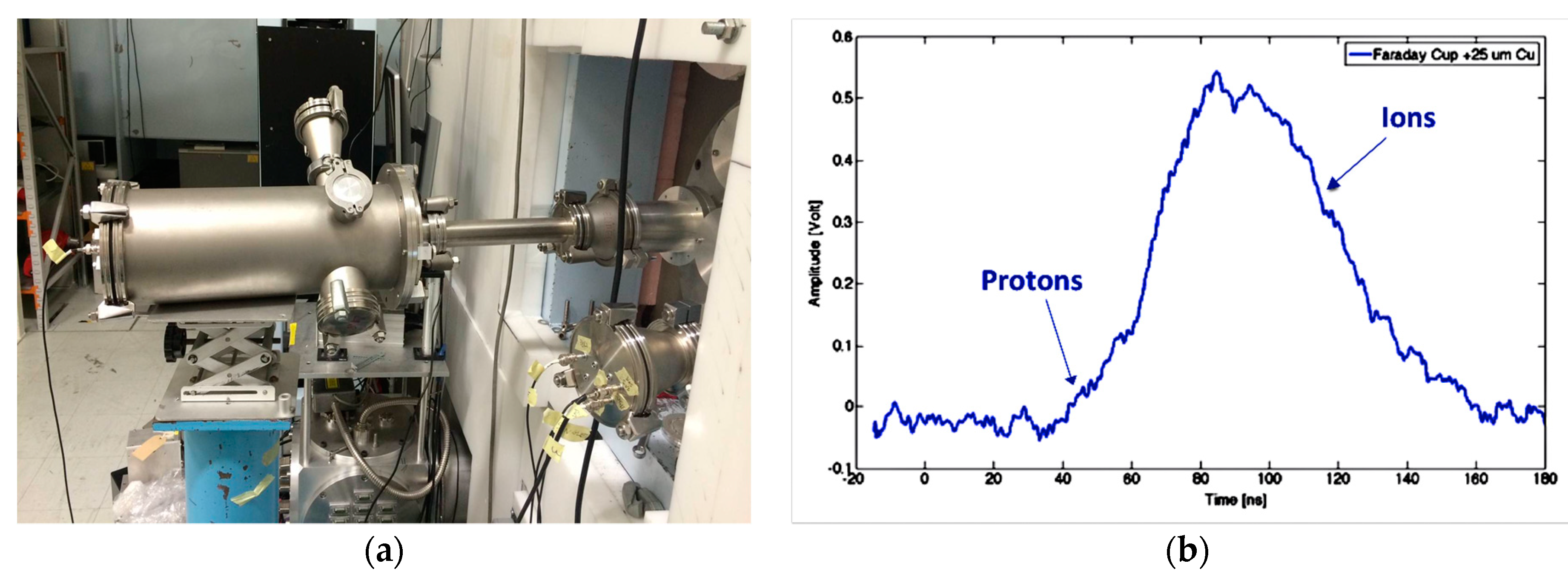
2.2. TOF: Description, Test, and Results

Energy spectrum, energy spread, angular distribution, and flux of the accelerated ion beam must be measured in real-time using very accurate methods. A specific on-line diagnostics system has been developed based on the TOF technique using diamond (polycrystalline and single crystal) and silicon carbide detectors. The TOF technique has been used extensively so far for the diagnosis of laser-accelerated proton and ion beams at low energy (up to ten’s MeV) and with low repetition rate laser systems [18,19]. Coupling such a technique with detectors as Faraday cups (FCs), ion collectors (ICs), or semiconductor-like detectors as diamond and silicon carbide ones, the biggest advantage of the TOF diagnostics is the capability to provide real-time measurement of the beam characteristics as energy cut-offs, distributions, and current and shot-to-shot reproducibility up to a repetition rate of 10 Hz. Nevertheless, the detection of intense ion/proton beams up to 100 MeV level, expected to be generated at ELIMAIA, with TOF method requires the use of fast detectors to disentangle the high-energy component of the beam.
A number of features, such as their radiation hardness, make diamond and silicon carbide detectors particularly attractive in harsh plasma environment, where many particles per bunch (up to 109) ionize the detector simultaneously. In fact, diamond detectors can be used in TOF geometry for ion measurements on a bunch-to-bunch basis at high laser repetition rates, or in particle counting mode, typically in particle physics for beam monitoring. The main advantages of these detectors compared with FCs or ICs are their large band-gap, which cuts out of the high intensity visible and UV light emission from the plasma and their fast response to detect fast particles in TOF. These features coupled with high signal-to-noise ratio, typical of diamond and silicon carbide detectors, make these detectors more attractive than other devices, such as FCs or ICs, for timing measurement of high-pulsed and high-energy ion beams [20,21].
The ELIMAIA TOF-based diagnostics system will be provided with at least three diamond detectors: one close to the interaction area (about 1 m from the target) as a part of the ion accelerator section and two detectors along the ELIMED transport and selection section (one will be placed about 2 m downstream the target, after the PMQ system and just before the energy selector injection point, and the other one will be placed about 9 m downstream the target, after the energy selection system). The TOF detector closer to the target, coupled with the TPS, will be used to characterize the particle beam (i.e., total ion current, shot to shot reproducibility) generated during the ion source optimization and, thanks to the diamond detector response, it will also allow to measure proton cut-off energies up to 50 MeV with an acceptable resolution even at such short distance from the target. The two detectors installed along the ELIMED section will allow one to monitor online the stability, the beam flux, and the energy spectrum of the proton beam focused by the PMQ system just before the selection in energy, and to measure the energy bandwidth and the flux of the proton beam selected shot to shot in real-time. The online beam parameter characterization given by the TOF measurement along the ELIMED transport and selection section will provide crucial information for transport optimization, also giving the possibility to tune “real-time” and adjust the PMQs and the ESS parameters according to the required beam specification.
The ELIMAIA TOF diagnostics consists of two single crystal diamond detectors, 140 μm and 500 μm thick, respectively, and a 100 μm thick polycrystalline diamond detector supplied by the CIVIDEC company. Particular care was taken for a proper shielding from the EMP, which typically follows the high power laser-matter interaction and the subsequent plasma production; all the detectors are provided by an aluminum housing specifically optimized for the EMP shielding with the electronic readout circuit is directly integrated in the detector PCB.
These detectors were tested at high power laser facilities in TOF measurements of the high energy laser-driven proton beams generated by the PW Vulcan laser system at the Rutherford Appleton Laboratory (RAL). The experiment was aimed at test diamond detector performances, using TOF technique, with high-energy (up to several tens of MeV) laser-accelerated protons in a laser environment characterized by strong EMP pulse, and compared the results with well-established diagnostics and techniques [21].
A novel analysis method was developed to extract the energy cut-offs, energy distribution, and fluence for energies higher than 10 MeV from the diamond detector TOF signals. The energy distribution and the fluence extracted from the TOF signal were compared with those measured using EBT3 Radiochromic film stacks and TPS coupled with image plate detectors, also allowing one to validate the new data processing method. Data analysis, results, and detailed description of the analysis procedure developed will be presented in following papers.
The laser of wavelength of 1.054 um and pulse duration of about 700 fs FWHM delivered up to about 400 J of energy on target in a single shot. The laser was focused on a 25 μm Al foil with an incidence angle of 20° with respect to the target normal by a f/3 off axis parabolic mirror.
Figure 4 show pictures of the diamond detectors placed inside the target chamber close to the TPS pinhole (a) and inside a pipe mounted in backward direction (b).
As an example of the obtained results, Figure 5 shows a typical TOF signal acquired with the 140 μm single diamond detector placed at 2.35 m from the target in the target front-side direction. A 500 μm Al foil was used in this shot in front of the diamond detector aperture to stop the most energetic heavy ions accelerated from the target (absorber thickness was chosen based on the TPS spectral analysis) and the low energy proton group. Because of the extreme intense high flux of laser-driven ion bunches, diamond detectors are used in current mode, namely an average current is measured.
A TOF signal structure consisiting of a peak arising from UV, X-rays, and fast electrons emitted from the target and a peak generated by the fast proton group can be observed in Figure 5a. Ions other than protons are stopped in the thick Al absorber placed in front of the detector. The short peak appearing at the beginning of time axis (7–12 ns) corresponds to the so-called photo-peak and fixes the starting point for the acquisition, that is, the trigger signal. As one can see in Figure 5a, the low sensitivity of the diamond detector to the plasma visible and soft-UV radiation reflects in a narrow photo-peak compared with other detectors such as Faraday cups and ion collectors, allowing to disentangle the high-energy proton component, characterized by short TOF, also at short flight path as in this case [18,21]. The Al filter allows selecting a TOF interval in which the signal, being uniquely generated from protons, can be directly converted in energy distribution using the analysis procedure developed for high-energy (up to 100 MeV level) proton spectrum reconstruction, which takes into account the detector response and the proton energy loss inside the detector thickness using a Monte Carlo approach. Figure 5b shows the proton energy distribution extract related to the TOF signal of Figure 5a. Proton energy cut-offs, distribution, and flux were compared with the ones obtained with the RCF stacks and the TPS placed at the same distance and similar angle with respect to the diamond detector. The comparisons, discussed elsewhere, show a rather good agreement confirming the reliability of TOF technique coupled with the use of diamond detectors and the developed analysis method for high-energy laser-accelerated proton diagnosis. These results also demonstrate that the resolution achievable in high-energy proton TOF measurements with such thin diamond detectors allows monitoring online key features of high energy protons accelerated from high-repetition rate laser systems, such as maximum ion energy and flux, up to 100 MeV level even at about 2 m from the source. Thanks to diamond`s time resolution, it will be also possible to measure the energy bandwidth of the proton beam selected downstream at a user beamline such as ELIMAIA [9]. Moreover, in order to provide measurement of the beam energy spectrum and cut-offs as a function of the emission angle from the source, which is extremely important to characterize the whole beam profile and angular distribution of ion beams with a broad angular aperture (typical divergence >30°), such as the ones accelerated by lasers, an array of diamond detectors, placed at different angles with respect to target normal direction, will to be assembled and tested.

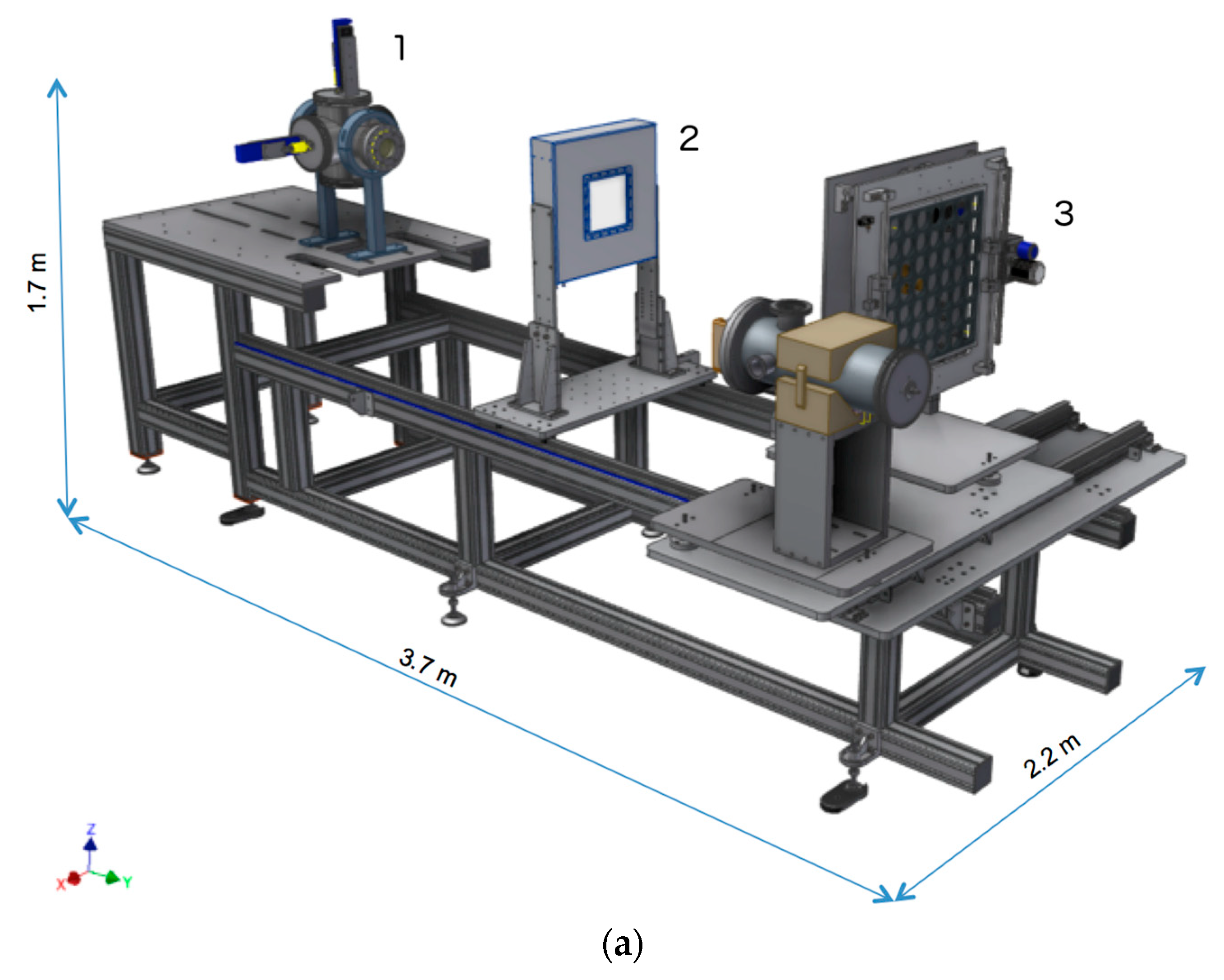
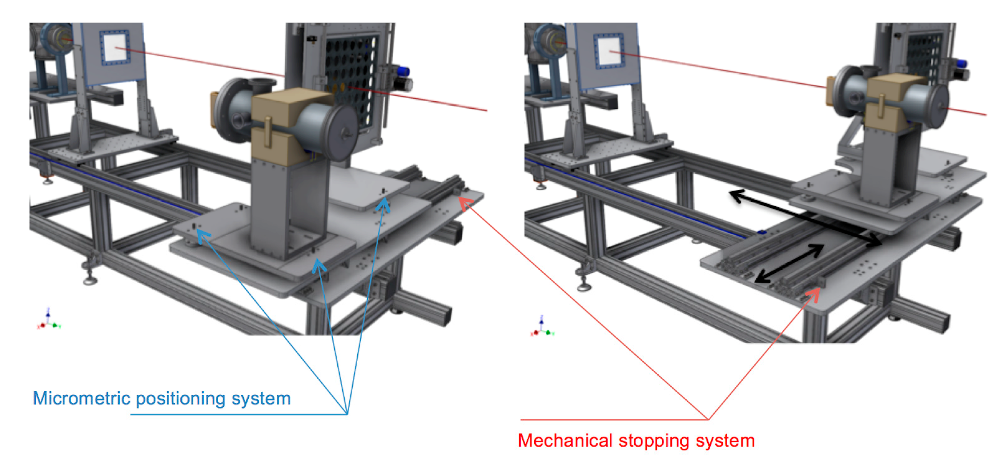
2.3. Emittance Diagnostics Device

In order to optimize the particle transport and injection from the PMQs system to the ESS, a beam emittance detector (BED) will be placed downstream the PMQs. A BED has been designed and realized and will be installed at ELIMAIA to characterize the ion beam focused by the ELIMED quadrupoles. The ELIMED BED is based on the pepper-pot operating principle, which converts the beam flux density as a function of position into a measurable signal, and consists of three main parts: a grid, a plastic scintillator, and an optical system (mirror + CCD camera). Acquired images will be elaborated in real-time using a dedicate software. Such a system can be inserted into the beam axis (reference trajectory) by a motorized system.

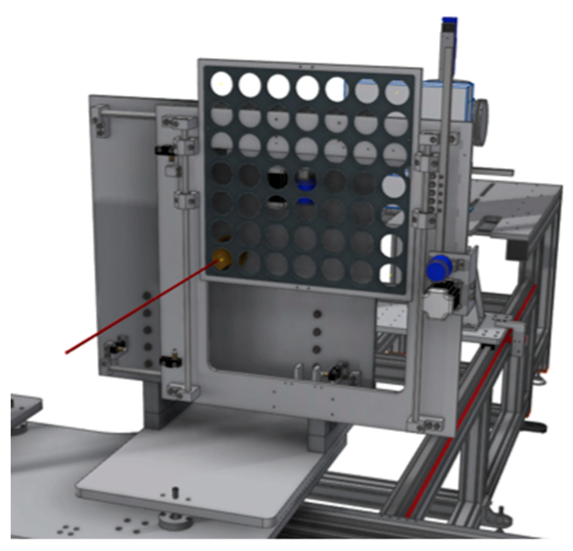
2.4. Single Shot Diagnostics

Detectors, working in single shot mode, will be also available at the ELIMAIA to provide a full characterization of the ion beam source, such as, for instance, RCF and nuclear track detectors such as CR39 type. A tower will be available in the ELIMAIA interaction chamber specifically designed for holding various types of film detectors organized in stacks, which will be used for “calibration shots”, to measure ion beam key parameters. Such a tower was designed to accommodate several film detector stacks.
RCF stacks will be used to reconstruct the energy spectrum of the incident particles. The dose deposited in each RCF layer is measured and by using an optical density-dose calibration factor and an iterative method it is possible to extract the particle energy spectrum [22,23]. An Al foil wrapping the stack is typically used for laser-driven ion beam diagnostics in order to shield the films from the UV and X rays coming from the laser-target interaction and to stop the heavy ion contribution (in case the proton energy spectrum needs to be measured). Several works in literature have shown the results obtained with this technique [24,25]. Moreover, the RCFs can be also used to measure the angular divergence and in particular the energy-angle dependence, also giving the 2D image of the beam shape in the transversal plane.
CR39 nuclear track detectors also represent a very convenient tool for time-integrated measurements of charged particle fluences as well as for neutron dosimetry based on the detection of recoil protons [26,27,28]. The main advantages of these detectors are their high sensitivity for ions within certain energy ranges and their insensitivity to photons and electrons for reasonable dose. Furthermore, such detectors are not affected by the intense electromagnetic pulse, which typically characterizes the laser environment. Each particle, going through a CR39 detector, damages the polycarbonate plastic material and generates a crater, which extends for a few tens of nanometres along the particle trajectory [29]. After a chemical etching procedure, in a non-saturation regime (typically less than 106 p/cm2), it is possible to detect permanent track structures using a professional microscope and to count the tracks. CR39 detectors are off-line dosimeters, giving a direct measurement of the particles fluence. The sizes of the crater, that is, the diameter, also depends on the ion species, the mass stopping power, and the parameters used during the etching procedure (i.e., the concentration of the chemical solution, the temperature, and the etching time) [30]. Therefore, by performing an energy calibration of such detector, it is also possible to perform a spectroscopic analysis of the CR39 by measuring the track diameter and extracting the corresponding incident energy given by the calibration procedure.

3. ELIMAIA Dosimetry Description

As a user multidisciplinary beam line aiming to explore the use of controllable and stable laser-drive proton/ion beams for applications, included the medical ones, the ELIMAIA beam line will be equipped of all the detectors required to perform accurate dosimetry and will provide all the tools to let the users carry out the proposed experiments. Devices for beam monitoring and detectors for relative and absolute dosimetry have been realized for accurately characterizing the beam shot-by-shot and they have been installing along the in-air final section of the ELIMAIA beamline [31]. They will be set up in a way that the relative position of these dosimeters can be easily changed according to the user needs, thus addressing different requirements in terms of transported energy and delivered dose.
Moreover, considering that different types of measurements will be performed, like, for instance, tests of new dosimeters, cell sample irradiations, characterization of novel devices for beam monitor, or imaging, the in-air final section of the beamline has been designed in a versatile way, accounting for the possibility of using small cell dishes as well as of placing heavier devices, quickly translating the objects in any allowed position.
In the next sections, a description of the main features of the in-air final section will be given, including the movable stages to be used for the user sample/detector positioning. The main functionalities of the detectors for dosimetry will be also reported.

3.1. The In-Air Final Section for Dosimetry and Sample Irradiation

In the ELIMAIA beamline, the transported particles, once selected in energy, will reach the in-air final section through a kapton window placed in a dedicated flange, separating this section from the in-vacuum one (Figure 6).
The same flange will also house the secondary emission monitor (SEM); which is one of the detectors composing the ELIMAIA dosimetric system; and a diamond detector for time of flight measurements; both controlled by dedicated actuators. The SEM is basically a beam current monitor that; once cross calibrated with a reference detector; can be also used as a on-line in-trasmission dose monitor. Moreover; thanks to the scattering of the incident protons; it contributes to the beam homogeneity at the final irradiation point. Further details on that will be given in the next section.
The total length of the in-air section is about 3 m and the relative positions of all the single-shot operating devices, as well as of the detectors for dosimetry can be easily changed, according to the user requirements.
A collimation system, aiming to cut the beam later tails, will be also included in order to provide the final shape of the beam at the irradiation point, with diameters ranging between few hundreds of μm up to 1 cm. Because of the flexibility of the system, both for position and beam diameter, it has not been included in the picture.
The first detector, which is traversed by the transported beam in air, is an in-transmission multi-gap ionization chamber (MGIC), aiming to on-line monitor the dose shot-by-shot (Figure 6). The MGIC is composed by two independent gaps, operated at different voltages, and it is a monitor that, once calibrated with an absolute detector for dosimetry, measures the dose delivered at the irradiation point. Specifically, the detector for measuring the absolute dose at the ELIMAIA beam line is a Faraday cup, which is able to measure the collected charge once coupled to an electrometer [32]. The information on the transported charge by the primary particles, coupled by a measurement of the beam area and the energy spectrum, provides the dose at the irradiation point. A sample irradiation system (SIS) can be easily placed at the same position where the beam has been previously calibrated, in order to deliver specific amounts of dose per sample, remotely controlling the sample positions (Figure 6). Further details for all the mentioned elements will be given in the next section. The output from the detectors is processed by a dedicated software, which collects the acquired signals and provides a feedback for the laser system, once the required dose at the irradiation point is achieved. Figure 6b shows a picture of the in-air final section for dosimetry and sample irradiation installed along the ELIMAIA beamline. All the elements are placed in translating stages assembled in linear rails, in order to easily change their relative positions (Figure 7).
In particular, both the MGIC and the stage where the SIS and the FC are mounted can be translated along the beam direction, in order to change their relative longitudinal position and to be placed closer to the kapton window, if low energy irradiations are performed. The SIS and FC can also be translated in the transversal direction in order to alternatively place them at the irradiation point. Each stage is also equipped with a micrometric positioning system for further tuning the final placement of the detectors, according to possible tiny variations of the beam direction. The realized system will allow to calibrate the beam and accurately irradiate samples, shot-by-shot monitoring the beam with a high level of precision, which is particularly required for medical applications and radiobiology experiments.

3.2. Detectors for Relative and Absolute Dosimetry

Provided that the transport elements will allow to obtain beams selected in energy and with low angular divergence, the beam temporal structure is anyway very different from the one characterizing conventionally accelerated beams. Indeed, high-intensity pulsed beams will reach the irradiation point, traversing all the dosimetric detectors with dose rates per pulse several order of magnitudes higher (i.e., up 108–109 Gy/s) with regard to the case of conventionally accelerated particles. As mentioned before, in order to perform accurate dosimetry of laser-driven ion beams in this extreme environment, alternative approaches have been adopted and new detectors have been developed, in the perspective of multidisciplinary applications at ELIMAIA.
In the following sections, a description of the detectors composing the ELIMAIA dosimetric system will be given.

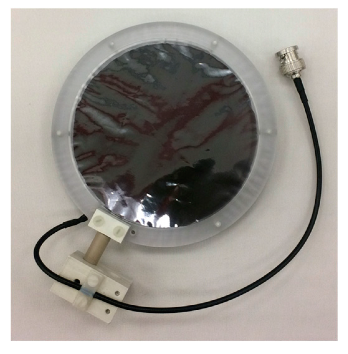
3.2.1. Secondary Electron Monitor

The SEM detector is a tantalum foil, 12.5 μm-thick, and with a diameter of 130 mm, provided with an electrically insulated PMMA circular frame (Figure 8).
Its working principle is based on the secondary electron emission; when charged particles pass through an interface of a solid material, very low energy electrons can be emitted from the surface [33]. The main parameter describing the secondary electron emission is the secondary emission yield, which is the average number of electrons emitted when an incident projectile passes through a surface and it is proportional to the energy loss of the particle in the surface layer [34]. The low energy secondary electron spectrum can be described by an exponential decay law. The number of secondary electrons generated increases with the energy released by the primary particles along the SEM thickness [35]. Therefore, the higher the incident beam energy, the lower the number of emitted electrons. According to Monte Carlo simulation results, energy losses in the Ta thickness between few hundreds of KeV up to about 1 MeV are predicted for beam energies from 60 MeV down to 5 MeV. The SEM is basically a beam current monitor, but it can be used as a device to measure the dose, once cross-calibrated against a reference dosimeter; indeed, a relationship between SEM current and the absorbed dose rate at a specified point in the radiation field can be found. The SEM detector will be mounted in a vacuum chamber, placed at the end of the in vacuum beam line section, and will be mainly used to monitor the beam flux in real time.
It will be provided with an actuator that will allow it to remove the detector from the beam axis when it is necessary.

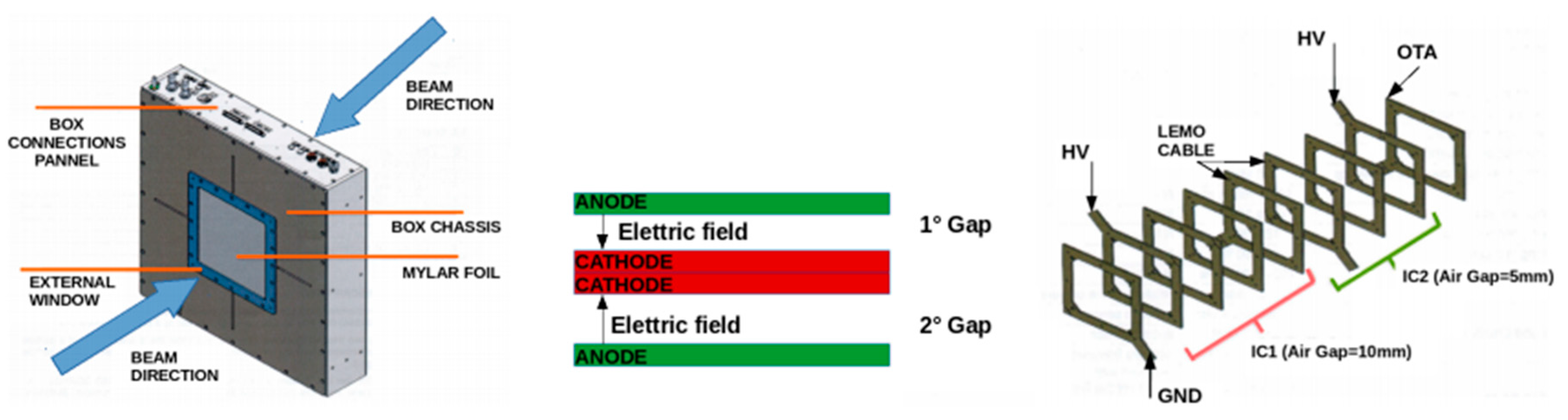
3.2.2. Multi-Gap Ionization Chamber

In order to address the issue related to the extremely high dose rate per pulse, a ionization chamber equipped with two separate electrodes collecting the charge in two independent gaps has been designed and realized for the ELIMAIA beam line. This approach, initially investigated for accurately determining corrections for ionization chambers used for absolute dosimetry [36], has been extended here for in-transmission monitor chambers. General recombination occurs when ions produced in different tracks recombine each other on their way to the collecting electrodes. The amount of this type of recombination depends on how many ions are created per unit volume and per unit time, consequently, general recombination is dose-rate dependent and, for laser-driven beams, it is expected to be relevant [37,38]. A solution could be provided by increasing the electric field but, in order to avoid large charge multiplication effects and, not least, a breakdown possibly caused by very high voltages, it is not possible to arbitrarily increase its value.
The double gap ionization chamber is intended to be a relative monitor detector, which still needs to be calibrated against an absolute dosimeter placed downstream the beamline (a Faraday cup, as described below). By the way, the poor shot-to-shot reproducibility arising large variations in the dose rate per pulse produces non negligible differences in the ion recombination, affecting a ionization chamber for different shots. Therefore, a unique value of collection efficiency cannot be provided if the beam conditions change considerably shot by shot. A real-time procedure to correct for the recombination for each independent shot must be implemented, in order to retrieve the respective collection efficiency and properly correct the chamber response for each shot. This is basically provided by the additional gap, which is used as a monitor for the first one, in order to provide a variable correction to be applied shot by shot to the first gap [39].
The device has been committed and realized by the DE.TEC.TOR. company and it is basically composed of two adjacent ionization chambers, with a gap (space between the electrodes) of 5 mm and 10 mm, respectively, and independently supplied (different voltage values according to the specific gap). The anode is constituted by a thin layer of 5 µm of copper and 2 µm of nichel deposited on a 25 µm layer of kapton, while the cathode is constituted by a 12 µm layer of aluminized mylar. Both of them are fixed by a frame of epoxy glass (Figure 9).
The two gaps are placed in the center of an aluminum box of 420 × 420 × 100 mm3 of size (Figure 9), and an external window of aluminized mylar is present in front. The modularity of the device will give the possibility to eventually add, in future, additional gaps for redundancy.

3.2.3. Faraday Cup

As pointed out before, in general, ion recombination effects in ionization chambers are relevant for these extremely high dose rates per pulse and, consequently, large corrections should be applied to properly account for these effects if ionization chambers should be used for absolute dosimetry of laser-driven beams. Although the use of in-transmission chambers to monitor the beam can be still feasible, provided that the adoption of alternative approaches, as the described double-gap configuration, can further optimize the final response, a detector independent as much as possible of beam intensity per pulse should be considered as the optimal choice for absolute dosimetry. This is important in order to properly cross-calibrate the in-transmission detectors with a reliable absolute detector, whose response is not sensibly influenced by high dose rate and the shot-to-shot non reproducibility. On this concern, the solution adopted at ELIMAIA relies on the use of a Faraday cup in order to determine the number of incident protons at the irradiation point along the in-air final section of the beamline. Knowing the incident proton energy and measuring the beam effective area is thus possible to determine the dose to water, once the stopping power values of protons in waters are retrieved from tables, aiming to obtain an overall uncertainty within 5% when beams are well-controlled and reproducible.
FCs are well known devices, their response is independent of the dose rate and, furthermore, they have been initially implemented in clinical proton facilities for absolute dosimetry, prior other methods based on the use of ionization chambers were definitively established and suggested in the protocols [40,41]. By the way, to determine the dose with an acceptable uncertainty, beyond the collected charge, all the mentioned quantities have to be measured with high level of accuracy. In particular, the collected charge in the cup, which finally provides the total number of incident protons, has to be optimized using an additional electrode (sometimes called electron suppressor), which aims to minimize undesired contribution in the charge, coming from secondary electrons. They are typically produced by the interaction of primary protons with either the entrance window used for maintaining vacuum conditions within the FC (electrons to be suppressed by the electric field) or with the cup itself, where the beam is dumped (electrons to be collected, because of escaping from the cup).
The FC designed and realized for ELIMAIA is 400 mm long, with an internal radius of 20 mm, and is made of aluminum. The main components are as follows: a 50 μm thick kapton entrance window to maintain the vacuum inside the cup, whose thickness has been chosen in order to minimize the beam perturbation; an additional electrode (suppressor) composed by a 180 mm steel cylinder; and a 50 mm thick aluminum cup where the charge is actually collected. Moreover, because the ionization of the residual air could affect the FC measurements, a vacuum of about 105 mbar is required as working condition. Figure 10 shows a picture of the FC installed in the ELIMAIA beamline.
A preliminary Monte Carlo study has been carried out with the aim of optimizing the size, according to the typical beam spot parameters expected at ELIMAIA, and of choosing the proper material that provides the best compromise between secondary electron production and mechanical handling [42]. To measure the beam effective area and the energy spectrum of the incident protons, radiochromic films (RCF) will be used at ELIMAIA. They are one of the most commonly used detectors for relative dosimetry and their independence on dose-rate has contributed to their wide use in the laser environment [43]. They are easy to handle and the physical information contained in the films is not lost during the reading process, allowing post-processing for additional data analysis. If coupled with professional scanners for the optical density measurements, a measurement of dose distribution with a spatial resolution within about 200 um can be achieved after a proper calibration. This is important to precisely measure the X and Y beam profiles, necessary to retrieve the beam effective area of the primary beam impinging on the FC. Moreover, if assembled in a stack configuration, RCFs can provide a measurement of the energy spectrum through an iterative procedure that, starting from the last irradiated film in proximity of the beam range, takes into account the different contributions in the the previous films and, in turn, the correspondant relative weight for the final energy spectrum [44,45].
Furthermore, EBT3 RCFs will be also used to measure the longitudinal dose distributions, assembling a single film in a dedicated PMMA phantom, divided in two identical parts, so that the film lies in a plane parallel to the beam direction (Figure 11). This approach, which can be further improved introducing post-processing corrections for high LET (Linear Energy Transfer) under-response, allows a precise measurement of the longitudinal dose distributions, and is particularly useful for quick determination of the beam range [45].
The ELIMAIA FC has been tested at high power laser facilities with the high energy laser-driven ion beams generated by the PW Vulcan laser system at the Rutherford Appleton Laboratory (UK). Such a preliminary characterization of the FC response in a laser environment has been performed during the experiment aimed at test the diamond-based ELIMAIA TOF diagnostics using the laser-target parameters described in Section 2.2. Figure 12 shows a picture of the FC connected to the target chamber through a pipe in backward direction at about 3 m from the target (Figure 12b). No kapton window was used to separate the FC from the target chamber during the test. A 25 μm Cu foil was used in front of the FC aperture to stop the low energy proton group. The main goals were to investigate the charge response of the FC to highly pulsed ion beams and the effect of the intense EMP generated in the laser-target interaction, on the FC signal. Figure 12a shows time signal acquired by the FC generated by the different accelerated ion species and charge states.
Particular care was taken to electrically isolate the FC from the chamber; different low pass-band filters were also used in the readout aiming to filter the EMP contribution from the ion current signal. As one can see, a positive current signal, resulting from the charge collected by the FC and corresponding in time to a signal generated by protons, carbon and oxygen ions (according to TPS data analysis, see Section 2.2), can be observed. In this case, because of the experimental configuration of the FC, the discrimination between proton and ion contributions was not possible.
Nevertheless, these preliminary tests allowed to characterize the charge response, optimize the signal to EMP noise ratio, and emphasize the charged particle signal with respect to the EMP.

3.2.4. Irradiation Procedures

The detectors for relative and absolute dosimetry described above will allow one to real-time monitor the beam and measure the dose per single shot, in order to provide a reliable characterization of the dosimetric parameters, necessary for multidisciplinary applications as, for instance, radiobiology experiments. Exploiting the possibility of easily changing the relative positions of the different detectors, shown in Section 3.1, a final irradiation configuration can be chosen according to the transported energy or to the specific user requirements. Once fixed, a preliminary beam characterization can be carried out using appropriate dosimetric detectors to determine the beam parameters, in terms of field size and beam range, also checking the transversal beam uniformity and its reproducibility.
After this preliminary characterization and, possibly, a further beam transport optimization, the cross-calibration of the in-transmission ionization chamber can be done against the FC, in order to retrieve the calibration factor that will be necessary for subsequent sample irradiations. These are actually performed by replacing the FC with the sample irradiation system, which will be placed at the same position of the FC along the beam axis (Figure 13).
The SIS is composed by a squared aluminum plane, physically connected to two stepping motors that control its movement in the X/Y directions with a total excursion of 400 mm and a resolution of 0.1 mm.
Different plexiglass masks can be mounted on the aluminum plane. The masks are constituted by many housings, whose size and shape will depend on the samples to be irradiated.
A second aluminum plane, thick enough to stop the most energetic protons, is mounted 5 cm away from the first one. This second plane is provided with a hole where additional collimators of different shapes and size can be mounted. The role of the second plane is basically to collimate the beam according to the user requirements and, at the same time, to shield the samples by the undesired radiation.
The translating stages will allow one to place user samples at the same point where the absolute dosimetry is performed. A dedicated software will allow remote and automatic control of the system movements; it will generate a feedback signal in order to start/stop the shots sequence according to the specific amount of dose required per sample, which will correspond to a specific number of shots.
Following the described approaches and after a preliminary tuning of the beam transport aiming to provide single shot doses of a few cGy, sample irradiations of the order of few Gy/min could be achieved, provided a laser repetition rate of about 1 Hz [31]. These are preliminary predictions, according to the Geant4 Monte Carlo code specially developed to simulate the ELIMED application line [42]. Indeed, the mentioned figures might be sensibly dependent on the laser-plasma source, both in terms of energy distribution and spatial profile, and also on the user requirements in terms of required beam size and spatial homogeneity at the sample.
The versatility of the ELIMAIA beamline and its installed equipment will allow it to deliver controllable and stable beams with accurately measured doses per shot, in the perspective of experimental activities aiming to demonstrate the feasibility of laser-driven beams for biomedical and muldisciplinary applications.

4. Conclusions

In this work, the status of the ELIMAIA diagnostics and dosimetry has been presented. The detectors developed for beam diagnostics, as well as the systems used for relative and absolute dosimetry have been described, showing the innovative aspects characterizing the solutions proposed in order to address the peculiarities of laser-driven ion beams. The devices described above, together with the magnetic elements composing the focusing and selection systems, will allow it to carry out multidisciplinary experiments with controllable beams, accurately monitoring shot by shot their physical parameters. Moreover, the realized dosimetric system will provide precise measurements of the delivered dose per shot, giving the opportunity to the future users of carrying out sample irradiations and dedicated experiments aiming to investigate the use of optically accelerated beams for medical applications.

Author Contributions

V.S. and F.R. have written the manuscript and carried out R & D of the described technologies; all the other authors have contributed in the R & D of the described technologies.

Acknowledgments

This work has been supported by the ELIMED activities supported by the V committee of INFN (Italian Insti- tute for Nuclear Physics); by the MIUR (Italian Ministry of Education, Research and University); by the Project LQ1606 funded by the Ministry of Education, Youth, and Sports as part of targeted support from the National Programme of Sustainability II; by the project Advanced research using high intensity laser produced photons and particles (CZ.02.1.01/0.0/0.0/16 019/0000789) from European Regional Development Fund (ADONIS); and by EPSRC (grant n. EP/K022415/1).

Conflicts of Interest

The authors declare no conflicts of interest.

Abbreviations

BEDBeam Emittance Detector
ELIExtreme Light Infrastructure
ELIMAIAELI Multidisciplinary Applications of laser-Ion Acceleration
ELIMEDELI MEDical applications
EMPElectro-Magnetic Pulse
ESSEnergy Selection System
FCFaraday Cup
ICIon Collector
IPImage Plates
LETLinear Energy Transfer
MGICMulti-Gap Ionization Chamber
PMQsPermanent Magnet Quadrupoles
TOFTime-Of-Flight
TPSThomson Parabola spectrometer
RCFRadiochromic Film
SEMSecondary Emission Monitor
SISSample Irradiation System

References

  1. Higginson, A.; Gray, R.J.; King, M.; Dance, R.J.; Williamson, S.D.R.; Butler, N.M.H.; Wilson, R.; Capdessus, R.; Armstrong, C.; Green, J.S.; et al. Near-100 MeV protons via a laser-driven transparency-enhanced hybrid acceleration scheme. Nat. Commun. 2018, 9, 724. [Google Scholar] [CrossRef] [PubMed]
  2. Wagner, F.; Deppert, O.; Brabetz, C.; Fiala, P.; Kleinschmidt, A.; Poth, P.; Schanz, V.A.; Tebartz, A.; Zielbauer, B.; Roth, M.; et al. Maximum proton energy above 85 MeV from the relativistic interaction of laser pulses with micrometer thick CH2 targets. Phys. Rev. Lett. 2016, 116, 205002. [Google Scholar] [CrossRef] [PubMed]
  3. Amaldi, U.; Kraft, G. Radiotherapy with beams of carbon ions. Rep. Prog. Phys. 2005, 68, 1861–1882. [Google Scholar] [CrossRef]
  4. Orecchia, R.; Zurlo, A.; Loasses, A.; Krengli, M.; Tosi, G.; Zurrida, S.; Zucali, P.; Veronesi, U. Particle beam therapy (Hadrontherapy): Basis for interest and clinical experience. Eur. J. Cancer 1998, 34, 459–468. [Google Scholar] [CrossRef]
  5. Malka, V.; Fritzler, S.; Lefebvre, E.; d’Humières, E.; Ferrand, R.; Grillon, G.; Albaret, C.; Meyroneinc, S.; Chambaret, J.; Antonetti, A.; et al. Practicability of protontherapy using compact laser systems. Med. Phys. 2004, 31, 1587–1592. [Google Scholar] [CrossRef] [PubMed]
  6. Hideghety, K.; Szabo, E.R.; Polanek, R.; Szabo, Z.; Ughy, B.; Brunner, S.; Tokes, T. An evaluation of the various aspects of the progress in clinical applications of laser driven ionizing radiation. J. Instrum. 2017, 12, C03038. [Google Scholar] [CrossRef]
  7. Bulanov, S.V.; Wilkens, J.J.; Esirkepov, T.Zh.; Korn, G.; Kraft, G.; Molls, M.; Khoroshkov, V.S. Laser ion acceleration for hadron therapy. Phys. Usp. 2014, 57, 1149–1179. [Google Scholar] [CrossRef]
  8. Ledingham, K.W.D.; Bolton, P.R.; Shikazono, N.; Ma, C.M.C. Towards Laser Driven Hadron Cancer Radiotherapy: A Review of Progress. Appl. Sci. 2014, 4, 402–443. [Google Scholar] [CrossRef] [Green Version]
  9. Margarone, D.; Cirrone, G.A.P.; Cuttone, G.; Amico, A.; Andò, L.; Borghesi, M.; Bulanov, S.S.; Bulanov, S.V.; Chatain, D.; Fajstavr, A.; et al. ELIMAIA: A laser-driven ion accelerator for multidisciplinary applications. Quantum Beam Sci. 2018, 2, 8. [Google Scholar] [CrossRef]
  10. The 3rd ELIMED Workshop MEDical and Multidisciplinary Applications of Laser-Driven Ion Beams at ELI-Beamlines (III ELIMED). Available online: http://iopscience.iop.org/journal/1748-0221/page/extraproc58 (accessed on 9 August 2018).
  11. Cirrone, G.A.P.; Cuttone, G.; Romano, F.; Schillaci, F.; Scuderi, V.; Amato, A.; Candiano, G.; Costa, M.; Gallo, G.; Larosa, G.; et al. Design and status of the ELIMED beam line for laser-driven ion beams. Appl. Sci. 2015, 5, 427–445. [Google Scholar] [CrossRef]
  12. Macchi, A.; Borghesi, M.; Passoni, M. Ion acceleration by superintense laser-plasma interaction. Rev. Mod. Phys. 2013, 85, 751. [Google Scholar] [CrossRef]
  13. Margarone, D.; Klimo, O.; Kim, I.J.; Prokůpek, J.; Limpouch, J.; Jeong, T.M.; Mocek, T.; Pšikal, J.; Kim, H.T.; Proška, J.; et al. Laser-Driven Proton Acceleration Enhancement by Nanostructured Foils. Phys. Rev. Lett. 2012, 109, 234801. [Google Scholar] [CrossRef] [PubMed]
  14. Klimo, O.; Psikal, J.; Limpouch, J.; Proska, J.; Novotny, F.; Ceccotti, T.; Floquet, V.; Kawata, S. Short pulse laser interaction with micro-structured targets: Simulations of laser absorption and ion acceleration. New J. Phys. 2011, 13, 053028. [Google Scholar] [CrossRef]
  15. Giuffrida, L.; Svensson, K.; Psikal, J.; Margarone, D.; Lutoslawski, P.; Scuderi, V.; Milluzzo, G.; Kaufman, J.; Wiste, T.; Dalui, M. Nano and micro structured targets to modulate the spatial profile of laser driven proton beams. J. Instrum. 2017, 12, C03040. [Google Scholar] [CrossRef]
  16. Margarone, D.; Velyhan, A.; Dostal, J.; Ullschmied, J.; Perin, J.P.; Chatain, D.; Garcia, S.; Bonnay, P.; Pisarczyk, T.; Dudzak, R.; et al. Proton Acceleration Driven by a Nanosecond Laser from a Cryogenic Thin Solid-Hydrogen Ribbon. Phys. Rev. X 2016, 6, 041030. [Google Scholar] [CrossRef]
  17. Opera Electromagnetic FEA Simulation Software. Available online: https://operafea.com/ (accessed on 9 August 2018).
  18. Margarone, D.; Krása, J.; Giuffrida, L.; Picciotto, A.; Torrisi, L.; Nowak, T.; Musumeci, P.; Velyhan, A.; Prokůpek, J.; Láska, L.; et al. Full characterization of laser-accelerated ion beams using Faraday cup, silicon carbide, and single-crystal diamond detectors. J. Appl. Phys. 2011, 109, 103302. [Google Scholar] [CrossRef]
  19. Marinelli, M.; Milani, E.; Prestopino, G.; Verona, C.; Verona-Rinati, G.; Cutroneo, M.; Torrisi, L.; Margarone, D.; Velyhan, A.; Krasa, J.; et al. Analysis of laser-generated plasma ionizing radiation by synthetic single crystal diamond detectors. Appl. Surf. Sci. 2013, 272, 104–108. [Google Scholar] [CrossRef] [Green Version]
  20. Milluzzo, G.; Scuderi, V.; Amico, A.G.; Borghesi, M.; Cirrone, G.A.P.; Cuttone, G.; De Napoli, M.; Doria, D.; Dostal, J.; Larosa, G.; et al. Laser-accelerated ion beam diagnostics with TOF detectors for the ELIMED beam line. J. Instrum. 2017, 12, C02025. [Google Scholar] [CrossRef]
  21. Scuderi, V.; Milluzzo, G.; Alejo, A.; Amico, A.G.; Booth, N.; Cirrone, G.A.P.; Doria, D.; Green, J.; Kar, S.; Larosa, G.; et al. Time of Flight based diagnostics for high energy laser driven ion beams. J. Instrum. 2017, 12, C03086. [Google Scholar] [CrossRef]
  22. Nurnberg, F.; Schollmeier, M.; Brambrink, E.; Blažević, A.; Carroll, D.C.; Flippo, K.; Gautier, D.C.; Geißel, M.; Harres, K.; Hegelich, B.M.; et al. Radiochromic film imaging spectroscopy of laser-accelerated proton beams. Rev. Sci. Instrum. 2009, 80, 033301. [Google Scholar] [CrossRef] [PubMed] [Green Version]
  23. Hey, D.S.; Key, M.H.; Mackinnon, A.J.; MacPhee, A.G.; Patel, P.K.; Freeman, R.R.; Van Woerkom, L.D.; Castaneda, C.M. Use of GafChromic film to diagnose laser generated proton beams. Rev. Sci. Instrum. 2008, 79, 053501. [Google Scholar] [CrossRef] [PubMed]
  24. Breschi, E.; Borghesi, M.; Galimberti, M.; Giulietti, D.; Gizzi, L.A.; Romagnani, L. A new algorithm for spectral and spatial reconstruction of proton beams from dosimetric measurements. Nucl. Instrum. Methods Phys. Res. Sect. A 2004, 522, 190–195. [Google Scholar] [CrossRef]
  25. Kirby, D.; Green, S.; Fiorini, F.; Parker, D.; Romagnani, L.; Doria, D.; Kar, S.; Lewis, C.; Borghesi, M.; Palmans, H. Radiochromic film spectroscopy of laser-accelerated proton beams using the FLUKA code and dosimetry traceable to primary standards. Laser Part Beams 2011, 29, 231–239. [Google Scholar] [CrossRef]
  26. Sadowski, M.; Al-Mashhadani, E.M.; SzydIowski, A.; Czyżewski, T.; Gtowacka, L.; Jaskóła, M.; Wieluński, M. Investigation on the response of CR-39 and PM-355 track detectors to fast protons in the energy range 0.2-4.5 MeV. Nucl. Instrum. Methods Phys. Res. Sect. B 1994, 86, 311–316. [Google Scholar] [CrossRef]
  27. Hegelich, B.M.; Albright, B.J.; Cobble, J.; Flippo, K.; Letzring, S.; Paffett, M.; Ruhl, H.; Schreiber, J.; Schulze, R.K.; Fernández, J.C. Laser acceleration of quasi-monoenergetic MeV ion beams. Nature 2006, 439, 441–444. [Google Scholar] [CrossRef] [PubMed]
  28. Jeong, T.W.; Singh, P.K.; Scullion, C.; Ahmed, H.; Hadjisolomou, P.; Jeon, C.; Yun, H.; Kakolee, K.F.; Borghesi, M.; Ter-Avetisyan, S. CR-39 track detector for multi-MeV ion spectroscopy. Sci. Rep. 2017, 7, 2152. [Google Scholar] [CrossRef] [PubMed]
  29. Sinenian, N.; Rosenberg, M.J.; Manuel, M.; McDuffee, S.C.; Casey, D.T.; Zylstra, A.B.; Rinderknecht, H.G.; Johnson, M.G.; Séguin, F.H.; Frenje, J.A.; et al. The response of cr-39 nuclear track detector to 1–9 mev protons. Rev. Sci. Instrum. 2011, 82, 103303. [Google Scholar] [CrossRef] [PubMed]
  30. Gaillard, S.; Fuchs, J.; Renard-Le Galloudec, N.; Cowan, T.E. Study of saturation of CR39 nuclear track detectors at high ion fluence and of associated artifact patterns. Rev. Sci. Instrum 2007, 78, 013304. [Google Scholar] [CrossRef] [PubMed]
  31. Romano, F.; Schillaci, F.; Cirrone, G.A.P.; Cuttone, G.; Scuderi, V.; Allegra, L.; Amato, A.; Amico, A.; Candiano, G.; De Luca, G.; et al. The ELIMED transport and dosimetry beamline for laser-drivenion beams. Nucl. Instrum. Methods Phys. Res. Sect. A 2016, 829, 153–158. [Google Scholar] [CrossRef]
  32. Cirrone, G.A.P.; Romano, F.; Scuderi, V.; Amato, A.; Candiano, G.; Cuttone, G.; Giovo, D.; Korn, G.; Krasa, J.; Leanza, R.; et al. Transport and dosimetric solutions for the ELIMED laser-driven beam line. Nucl. Instrum. Methods Phys. Res. Sect. A 2015, 796, 99–103. [Google Scholar] [CrossRef]
  33. Sternglass, E.J. Theory of Secondary Electron Emission by High-Speed Ions. Phys. Rev. 1957, 108, 1. [Google Scholar] [CrossRef]
  34. Hasselkamp, D.; Rothard, H.; Groeneveld, K.O.; Kemmler, J.; Varga, P.; Winter, H. Particle Induced Electron Emission II; Springer: Berlin, Germany, 1992. [Google Scholar]
  35. Badano, L.; Ferrando, O.; Klatka, T.; Koziel, M.; Molinari, G.; Abbas, K.; Braccini, S.; Bulgheroni, A.; Caccia, M.; Gibson, P.N.; et al. Laboratory and in-beam tests of a novel real-time beam monitor for hadrontherapy. IEEE Trans. Nucl. Sci. 2005, 52, 830–833. [Google Scholar] [CrossRef]
  36. Palmans, H.; Thomas, R.; Kacperek, A. Ion recombination correction in the Clatterbridge Centre of Oncology clinical proton beam. Phys. Med. Biol. 2006, 51, 903. [Google Scholar] [CrossRef] [PubMed]
  37. Boag, J.W. Ionization chambers. Radiat. Dosim. 1966, 2, 2–72. [Google Scholar]
  38. Boag, J.W. Ionization measurements at very high intensities—Part I. British J. Radiol. 1950, 2, 601–611. [Google Scholar] [CrossRef] [PubMed]
  39. Guarachi, L.F.; Sacchi, R.; Giordanengo, S.; Marchetto, F.; Talpacci, E.; Monaco, V.; Stasi, M.; Donetti, M.; Vignati, A.; Anvar, M.V.; et al. TH-CD-BRA-08: Multi-Gap Ionization Chamber for High-Flux Charged Particle Beams. Med. Phys. 2016, 42, 3727. [Google Scholar] [CrossRef]
  40. Cambria, R.; Hérault, J.; Brassart, N.; Silari, M.; Chauvel, P. Proton beam dosimetry: A comparison between the Faraday cup and an ionization chamber. Phys. Med. Biol. 1997, 42, 1185–1196. [Google Scholar] [CrossRef] [PubMed]
  41. Cuttone, G.; Raffaele, L.; Tonghi, L.; Fattibene, P. First Dosimetry Intercomparison Results for the CATANA Project. Phys. Med. 1999, 15, 121–130. [Google Scholar]
  42. Milluzzo, G.; Pipek, J.; Amico, A.G.; Cirrone, G.A.P.; Cuttone, G.; Korn, G.; Larosa, G.; Leanza, R.; Margarone, D.; Petringa, G.; et al. Geant4 simulation of the ELIMED transport and dosimetry beam line for high-energy laser-driven ion beam multidisciplinary applications. Nucl. Instrum. Methods Phys. Res. Sect. A 2018, arXiv:1802.03745. [Google Scholar] [CrossRef]
  43. Karsch, L.; Beyreuther, E.; Burris-Mog, T.; Kraft, S.; Richter, C.; Zeil, K.; Pawelke, J. Dose rate dependence for different dosimeters and detectors: TLD, OSL, EBT films, and diamond detectors. Med. Phys. 2012, 39, 2447–2455. [Google Scholar] [CrossRef] [PubMed]
  44. Jaccard, M.; Petersson, K.; Buchillier, T.; Germond, J.F.; Durán, M.T.; Vozenin, M.C.; Bourhis, J.; Bochud, F.O.; Bailat, C. High dose-per-pulse electron beam dosimetry: Usability and dose-rate independence of EBT3 Gafchromic films. Med. Phys. 2017, 44, 725–735. [Google Scholar] [CrossRef] [PubMed]
  45. Carnicer, A.; Angellier, G.; Gérard, A.; Garnier, N.; Dubois, C.; Amblard, R.; Hérault, J. Development and validation of radiochromic film dosimetry and Monte Carlo simulation tools for acquisition of absolute, high-spatial resolution longitudinal dose distributions in ocular proton therapy. Radiat. Meas. 2013, 59, 225–232. [Google Scholar] [CrossRef]
Figure 1. The main sections of the ELI multidisciplinary applications of laser-ion acceleration (ELIMAIA) beamline (ion accelerator and ELI medical and multidisciplinary applications (ELIMED)) consist of different subsystems: acceleration, collection, and diagnostics; selection, transport, and diagnostics; and dosimetry and sample irradiation [9].
Applsci 08 01415 g001
Figure 2. (a) Picture of the ELIMAIA Thomson parabola spectrometers (TPS); (b) SIMION simulation of the TPS performances.
Applsci 08 01415 g002
Figure 3. Details of the ELIMAIA TPS: (left) pinhole, magnetic and electric electrodes (TPS inside view), (top right) micro channel plate and (bottom right) high voltage power supplies.
Applsci 08 01415 g003
Figure 4. (a) Picture of the detectors installed in target chamber; (b) Picture of the experimental setup.
Applsci 08 01415 g004
Figure 5. (a) Time-of-flight (TOF) signal acquired with a 140 μm single crystal diamond detector at 2.35 m downstream the target; (b) Proton energy spectrum extracted from the TOF signal is shown on the left.
Applsci 08 01415 g005
Figure 6. (a) 3D model of the in-air final section of the ELIMAIA beam line. Transported particles come from the left: (1) flange, separating the two sections of the beamline and housing the secondary emission monitor (SEM) and TOF detectors. (2) Ion collector (IC) for the in-transmission dose monitoring. (3) Final irradiation point, including the Faraday cup (FC) and sample irradiation system (SIS), respectively, used for absolute dosimetry and sample irradiation. All the elements are installed in translating stages to change their relative position; (b) picture of the in-air final section for dosimetry and sample irradiation installed along the ELIMAIA beamline.
Applsci 08 01415 g006aApplsci 08 01415 g006b
Figure 7. Diagram of the in-air final section of the ELIMAIA beam line, where the positioning system is visible. On the left and right are shown the different positions for respectively centering the FC and the SIS respect to the beam axis (in red).
Applsci 08 01415 g007
Figure 8. Picture of the SEM detector developed for the ELIMAIA beamline.
Applsci 08 01415 g008
Figure 9. An overview of multi-gap ionization chamber (MGIC), the scheme of electrode and the sensors package composed of frames used in stack, in order to separate the cathodes and the anodes and to support the MGIC at the center of the box. In the sensors package (on the right), IC1 is indicated by the red bracket and IC2 by the green bracket.
Applsci 08 01415 g009
Figure 10. Picture of the FC installed along the in-air section of the ELIMAIA beamline.
Applsci 08 01415 g010
Figure 11. (a) PMMA phantom used to fix the radiochromic film (RCF) for longitudinal dose distributions; (b) An example of RFC irradiated with conventionally accelerated 62 MeV proton beams using the mentioned phantom, where it is clearly visible the increasing of darkness (and consequently, of dose) in proximity of the beam range.
Applsci 08 01415 g011
Figure 12. (a) Picture of the ELIMAIA FC installed in target chamber; (b) Ion signal acquired by the FC at about 3 m from the target.
Applsci 08 01415 g012
Figure 13. 3D model rendering of the sample irradiation system.
Applsci 08 01415 g013

