Fire Behavior of U-shaped Steel Beams Filled with Demolished Concrete Lumps and Fresh Concrete

State Key Laboratory of Subtropical Building Science, South China University of Technology, Guangzhou 510640, China
*
Author to whom correspondence should be addressed.
Appl. Sci. 2018, 8(8), 1361; https://doi.org/10.3390/app8081361
Submission received: 3 July 2018
/
Revised: 3 August 2018
/
Accepted: 10 August 2018
/
Published: 13 August 2018
(This article belongs to the Special Issue Emerging Construction Materials and Sustainable Infrastructure)
Abstract
:To reuse waste concrete in a more straightforward and simplified way, a new kind of structural member containing fresh concrete (FC) and demolished concrete lumps (DCLs) distinctly larger than conventional recycled aggregates has been proposed. Previous research has shown that, at room temperature, the mechanical performance of the U-shaped steel beams filled with DCLs and FC is similar to that of the U-shaped steel beams filled with FC alone. This research explores the fire behavior of the U-shaped steel beams filled with DCLs and FC. Five specimens including three beams filled with DCLs and FC and two reference beams filled with FC alone were tested in fire. The experimental parameters included the replacement ratio of DCLs, the longitudinal reinforcement ratio, the load ratio, and the thickness of fire insulation. Based on the test results, numerical models in which the thermal resistance at the interface between the U-shaped steel and the in-filled concrete is considered are developed using SAFIR to determine the thermal and structural responses of the specimens. Lastly, parametric studies are carried out preliminarily to investigate the effects of some parameters on the fire resistance of such beams. It is found that the replacement ratio of DCLs within a range of 0% to 33% has a very limited effect on the temperature distribution, structural response, and fire resistance of the specimens, that embedding longitudinal reinforcements can significantly increase the fire resistance of such beams, that the interface thermal resistance can generate a temperature drop of up to 280 °C at the interface between the U-shaped steel and the in-filled concrete, and that the numerical models are capable of predicting the thermal and structural responses of such beams.
1. Introduction
Recycling waste concrete contributes to environmental protection and reduces the depletion of this natural resource [1]. It has been extensively investigated in recent decades. Ongoing research is mainly related to recycled aggregate concrete (RAC), which is produced by substituting all or part of natural aggregates with recycled aggregates (i.e., crushed and sieved waste concrete debris). A series of studies on the mechanical properties [2,3], thermal performance [4], and durability [5] of RAC and on the performance of structural members with RAC (including slabs [6], beams [7,8], columns [9], wallboard [10], and frames [11]) have been carried out worldwide. Positive findings from these studies support and encourage the application of RAC in real buildings and structures. Guidelines and specifications for RAC have been documented by some researchers and organizations [12,13,14].
Although RAC provides an attractive means of recycling waste concrete, manufacturing high-quality recycled aggregate is still complicated and time-consuming and energy-consuming in actual practice since fine crushing, screening, and purification are needed. At present, a large amount of waste concrete still ends up at waste disposal sites. In order to reuse waste concrete in a more straightforward and simplified way, a new kind of structural member containing both fresh concrete (FC) and demolished concrete lumps (DCLs) with a distinctly larger size than conventional recycled aggregates (e.g., 60 mm to 300 mm for DCLs versus ≤31.5 mm for recycled aggregates, according to the Chinese standard) has been proposed by the authors [15]. In this way, waste concrete only needs to be coarsely crushed into large pieces and both the old aggregates and the old mortar in the waste concrete can be reused. The unit energy consumption and the cost of producing DCLs are, therefore, significantly reduced [16].
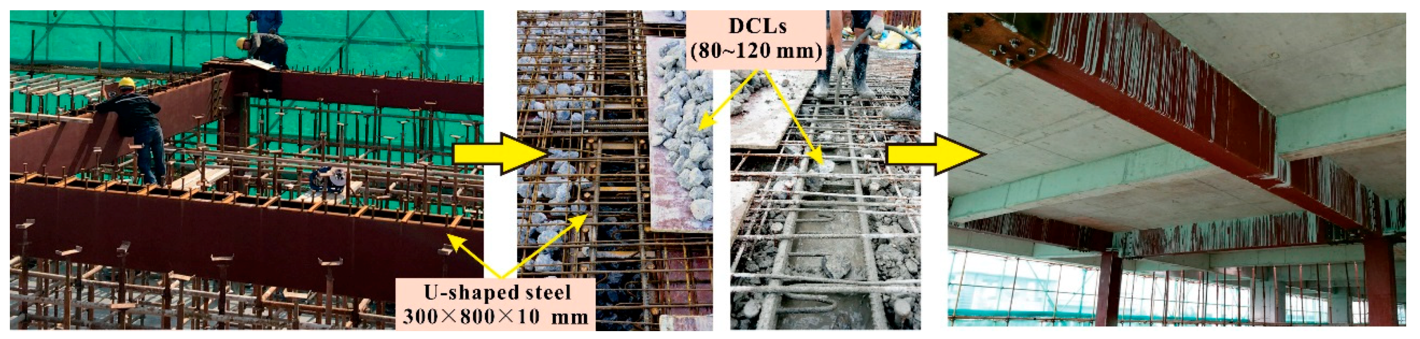
A series of studies on structural members containing DCLs has been carried out over the past decade. They have involved flexural and shear tests on reinforced concrete beams containing DCLs [15], compressive and cyclic loading tests of steel tubes filled with DCLs and FC [17,18], flexural tests of U-shaped steel beams filled with DCLs and FC [19], cyclic loading tests of composite shear walls filled with DCLs and FC [20], tests of composite slabs filled with DCLs, and FC at room temperature and in fire [21,22], and compressive tests of FRP-confined compound concrete containing DCLs [23]. It is found that, when the compressive strength of demolished concrete is close to that of FC, the mechanical behavior, seismic performance, and fire resistance of structural members containing DCLs are similar to or only slightly inferior to those of conventional members made of FC alone. In recent years, structural members (including columns, beams, and slabs) containing DCLs have been successfully applied in real building structures [24,25]. Figure 1 shows the application of the U-shaped steel beams filled with DCLs and FC in a real office building.
Hollow U-shaped steel can serve as formwork and reinforcement for in-filled concrete. In addition, putting DCLs into hollow U-shaped steel is more convenient than placing DCLs into steel reinforcement cages composed of longitudinal bars and stirrups, which makes it an effective way to reuse DCLs in concrete filled U-shaped steel beams. Tests have shown that U-shaped steel beams filled with DCLs and FC have comparatively satisfactory flexural behavior at room temperature [19], but further research on the fire behavior of such beams is necessary especially considering that the U-shaped steel is not embedded in the concrete. The effect of interface thermal resistance on the fire behavior of concrete filled steel tubes has been investigated numerically by Ding and Wang [26] and by Tao and Ghannam [27], but it remains unknown whether their findings are applicable to concrete filled U-shaped steel beams because the cross section and loading pattern of such beams are quite different from those of steel tubular columns filled with concrete.
The objective of this study is to reveal the influences of DCLs and longitudinal reinforcements on the fire behavior of the U-shaped steel beams filled with DCLs and FC and to clarify the effect of interface thermal resistance on temperature profiles in such beams. Three U-shaped steel beams filled with DCLs and FC and two reference beams filled with FC alone were tested in the fire. Numerical models are then developed using SAFIR to determine the thermal and structural responses of the specimens and the calculated results are compared with the test data. Lastly, parametric studies are carried out to further explore the effects of load ratio, thickness of fire insulation, and longitudinal reinforcement ratio on the fire resistance of such beams. The findings of this paper provide a basis for the fire-resistance design of the U-shaped steel beams filled with DCLs and FC.
2. Experimental Program
2.1. Test Specimens
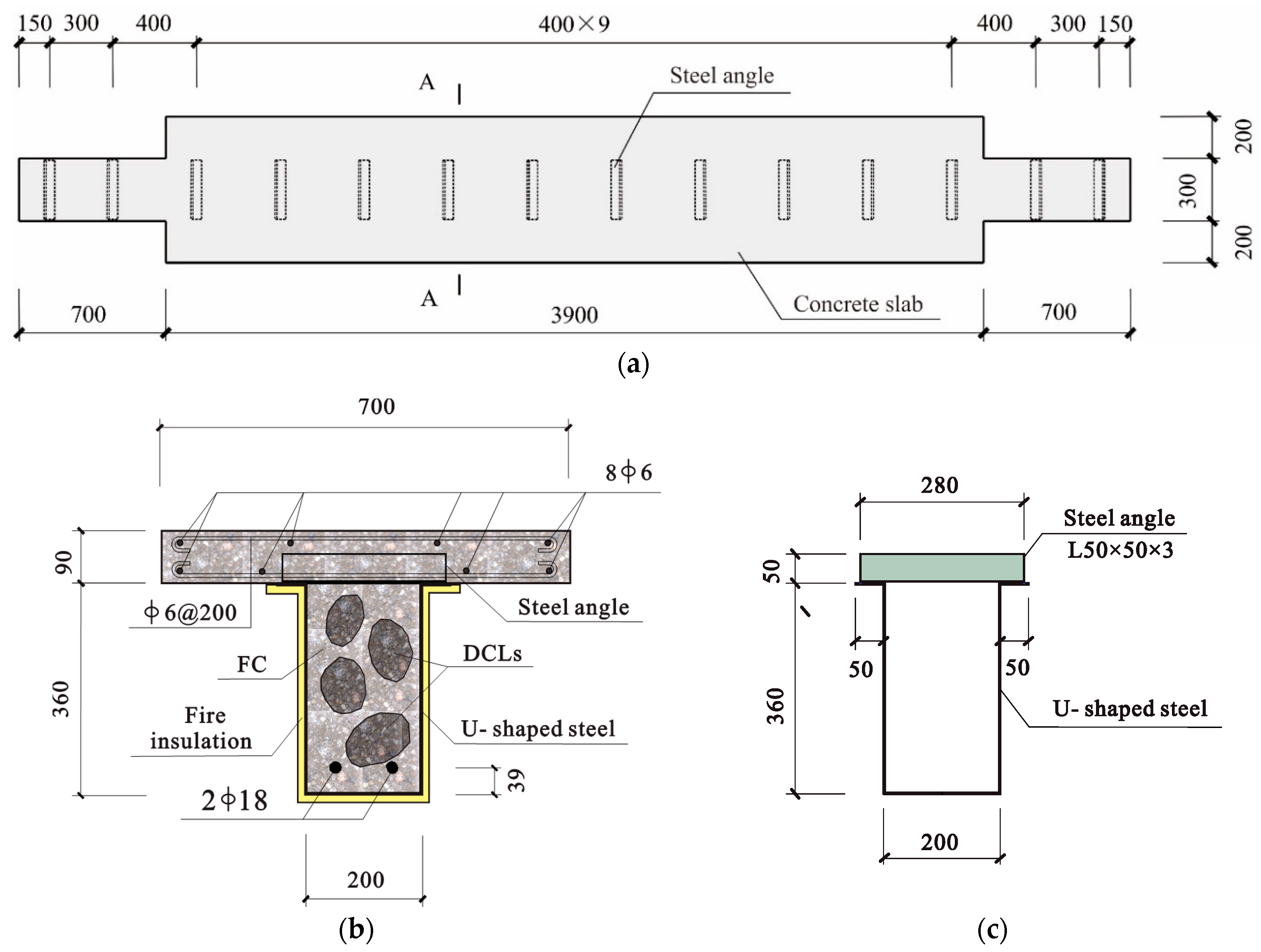
Five beam specimens including three beams filled with DCLs and FC and two reference beams filled with FC alone were fabricated. All the specimens were 5300 mm long and mounted with the same clear span of 4400 mm. Steel plate with a nominal thickness of 3 mm (the measured value was 2.4 mm) was processed by a bending machine to form the U-shaped steel. L 50 × 50 × 3 mm steel angles with a length of 280 mm were welded to the top flanges of the U-shaped steel to transfer the longitudinal shear force between the steel and the in-filled concrete. The steel angles were positioned 400 mm apart along the clear span of the specimens. The measured yield strength and ultimate strength of the steel angles were, respectively, 286.4 MPa and 421.8 MPa. For each specimen, the thickness of the concrete slab was 90 mm and the slab was 300 mm wide at both ends and 700 mm wide in the middle to match the size of the furnace chamber. Double-layer bidirectional steel mesh was incorporated in the slab and steel bars 6 mm in diameter were employed as the longitudinal reinforcements (8φ6) and transverse reinforcements (φ6@200). The measured yield strength of the steel bars was 358 MPa. Schematic diagrams of the specimens are given in Figure 2.
The parameters considered in the tests included the replacement ratio of DCLs η (0% or 33%), the longitudinal reinforcements located at the lower part of the beam (none or 2φ18), the thickness of fire insulation t (10 mm or 18 mm), and the load ratio n (0.45 or 0.625). In this study, the replacement ratio η is a ratio of the weight of DCLs in the U-shaped steel to the total weight of the in-filled concrete and n denotes a ratio of the applied bending moment at the mid-span section to the flexural capacity of the specimen at room temperature calculated according to the formulas proposed by Wu and Ji [19]. Those formulas are derived from plasticity theory and have been validated in the test of U-shaped steel beams filled with DCLs and FC at room temperature [19]. Table 1 gives the details of the specimens. In this table, ρs is the longitudinal reinforcement ratio. N is the load applied by the hydraulic jack and R is the measured fire resistance of the specimen. The effect of the replacement ratio on fire behavior of the beams can be revealed by comparing the test results of Specimen B1 (B2) with those of Specimen B3 (B4). The influence of the longitudinal reinforcements on fire performance of the beams can be examined by comparing the test results of Specimen B1 (B3) with those of Specimen B2 (B4). For Specimens B4 and B5 subjected to the same applied load, the beneficial effect of increasing fire insulation thickness on the beam’s fire resistance is compared with that of embedding longitudinal reinforcements.
The fresh concrete for all the beams came from one batch of ready-mix. The demolished concrete was obtained from RC beams, which had served as a retaining and protection structure during excavation of the foundations for 16 months. Fifteen core samples (100 mm in diameter by 100 mm in height) were drilled from the waste beams and the compressive strength of these samples was measured. The measurements were used to estimate the 150 mm cubic compressive strength of the demolished concrete (i.e., fcu, old in Table 1), according to the Chinese standard JGJ/T 384-2016 [28]. The proportions of fresh and demolished concrete are shown in Table 2. Both the fresh and the demolished concrete were made from Portland blast furnace-slag cement (P.S.A 32.5), natural crushed limestone (coarse aggregate) with a maximum size of about 20 mm, and local river sand (fine aggregate, 0–4 mm). The test-day 150 mm cubic compressive strength of the fresh concrete (fcu, new) is given in Table 1.
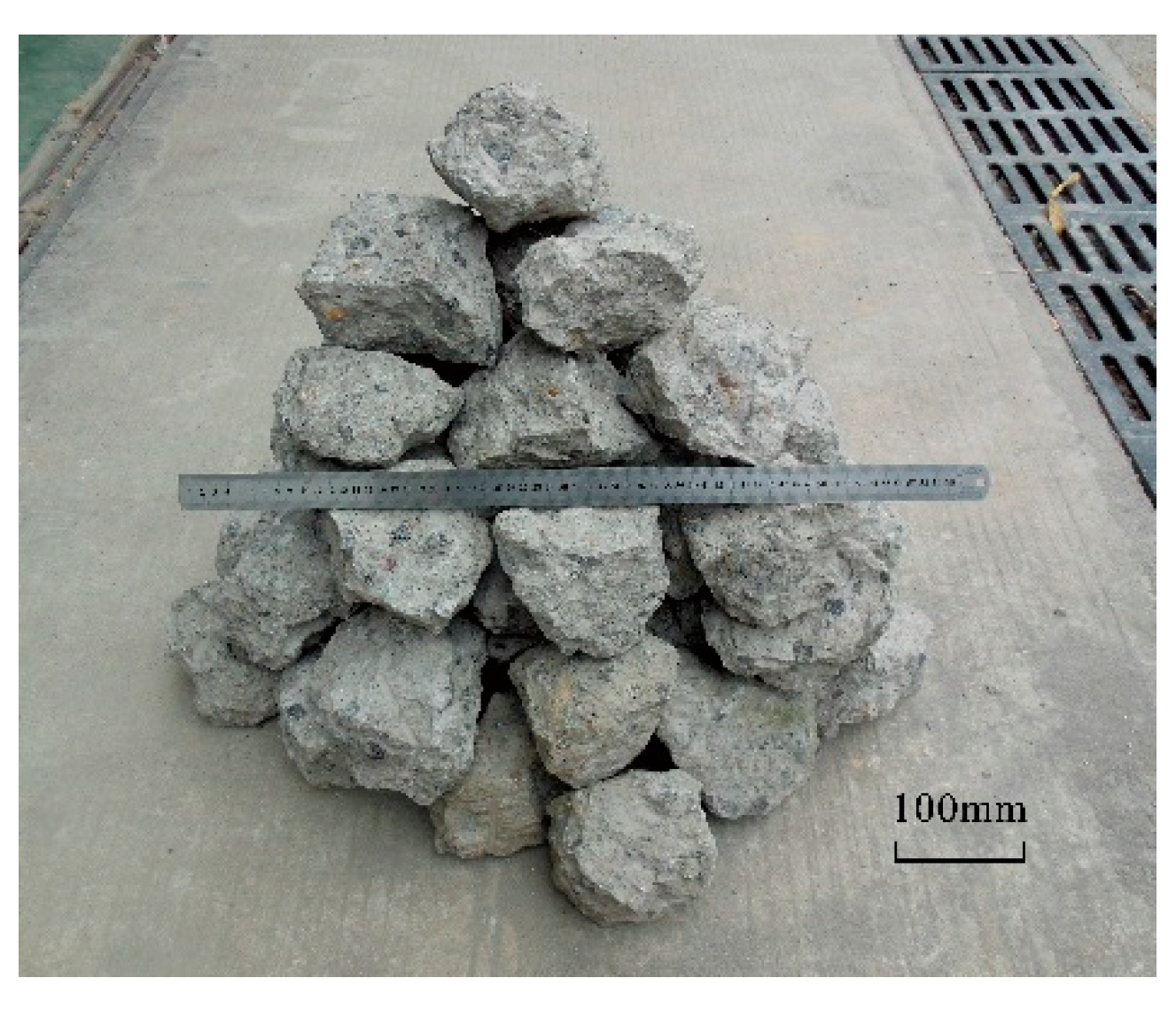
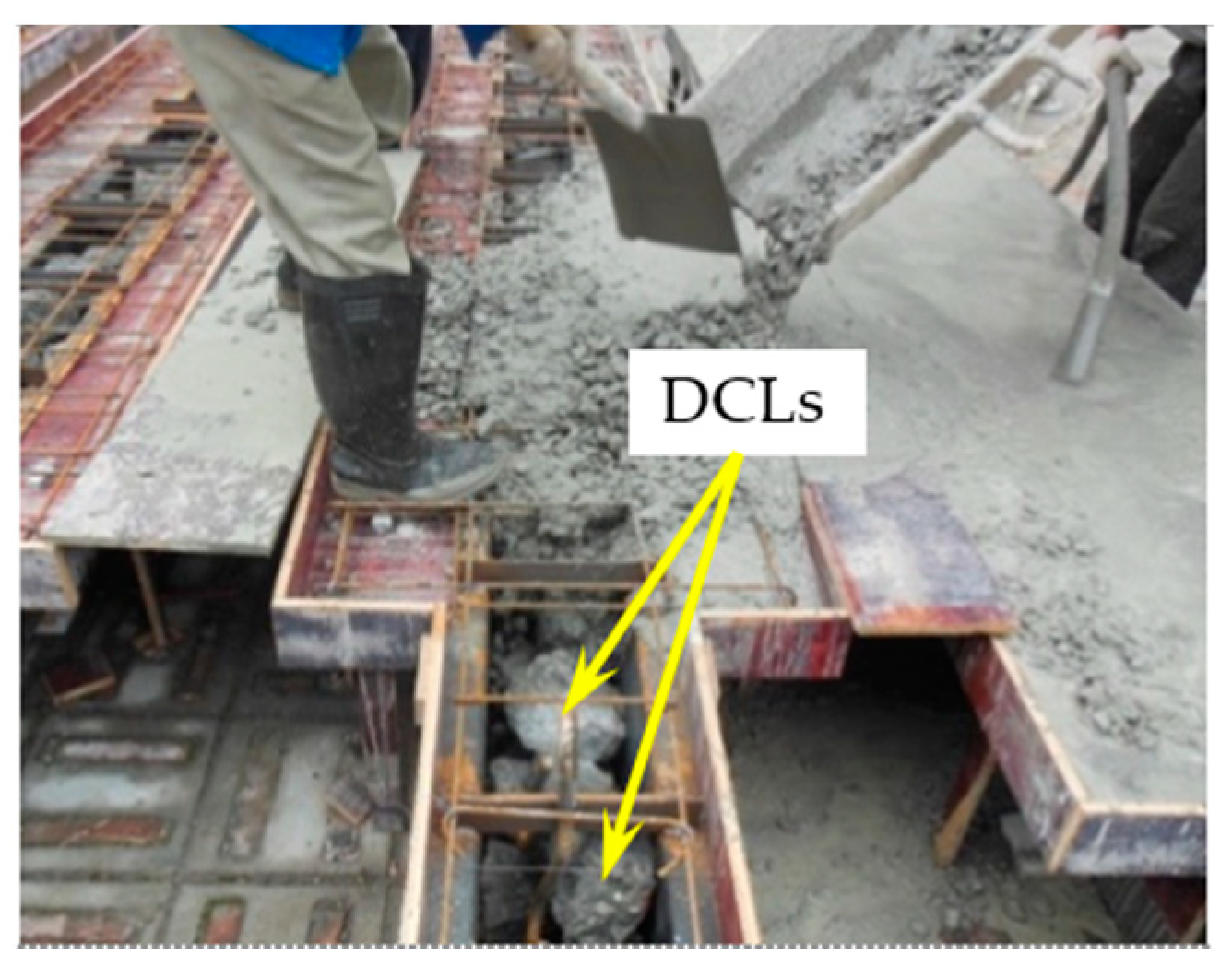
The waste beams were broken into 120 mm to 180 mm lumps using a pneumatic drill and other simple tools, as shown in Figure 3. For the specimens containing DCLs and FC, all of the DCLs were dampened by watering first and then were put into the U-shaped steel at the same time (see Figure 4). Fresh concrete was then poured around the lumps with a continuous vibration to ensure proper filling, compactness, and uniformity. The whole process including breaking of the waste RC beams and concrete casting of the specimens took about one month. All the specimens were cured at room temperature for about eight months before the fire test.
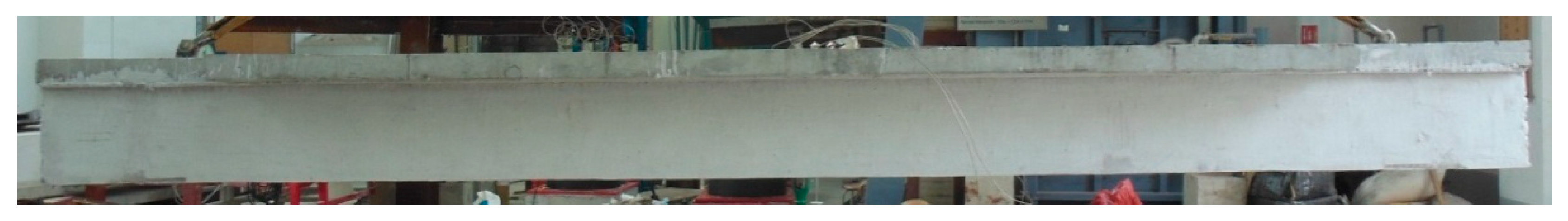
The fire insulation is of a new type developed using rice husk ash as heat insulation aggregate and alkali-activated metakaolin geopolymer as inorganic binder [22]. Tests have shown that it has excellent thermal insulating properties. The thermal conductivity and mass density of the fire insulation were measured at room temperature and the results were 0.0806 W/m K and 620 kg/m3, respectively. The fire-retardant coating was applied to the surface of the U-shaped steel (see Figure 1b) and then was cured at room temperature for at least four months before the fire tests were carried out. Figure 5 shows a photo of a specimen before the fire test.
2.2. Test Setup and Procedure
The specimens were tested in a 4000 × 3000 × 1500 mm furnace chamber at South China University of Technology. For each specimen, it was simply supported on two opposite walls of the furnace chamber and was heated over a length of 4000 mm. The beam had three exposed faces (the soffit and the two side surfaces) and the slab had one (the soffit) heated during the fire test. A schematic diagram of the test setup is displayed in Figure 6.
The vertical load was applied using a hydraulic jack with a loading capacity of 1000 kN and three distributive beams. The four loading points on the specimen were at 550 mm, 1650 mm, 2750 mm, and 3850 mm away from the support. Before the actual loading, each specimen was pre-loaded to lessen the adverse impacts on the test data due to the loading system. After pre-loading, the vertical load (see Table 1) was applied to the specimen about 20 min before the fire test and then was maintained at an almost constant value during the test. The sum of the applied load, the total weight of the three distributive beams (7.5 kN), and the weight of the specimen itself (3.4 kN/m) was employed to determine the applied bending moment at the mid-span section and the load ratio of the specimen. A photo of a specimen during the fire test is shown in Figure 7.
For each specimen, the fire test ended when the applied load could no longer be maintained. According to ISO 834-1 [29], the fire resistance of a specimen is reached when the mid-span deflection reaches L2/(400 d) mm (107.5 mm for these specimens). L is the clear span of the specimen and d is the distance between the extreme fiber of the compression zone and that of the tensile zone on the cross section. The rate of deflection criteria is not applied because 107.5 mm is less than L/30.
Two linear variable differential transducers (LVDTs) having a calibrated range of 200 mm and an accuracy of 0.03 mm were employed to measure the mid-span deflection of the specimens during the fire tests. At the same time, any settlement of the supports was monitored using two dial indicators with a calibrated range of 30 mm and an accuracy of 0.01 mm (see Figure 6).
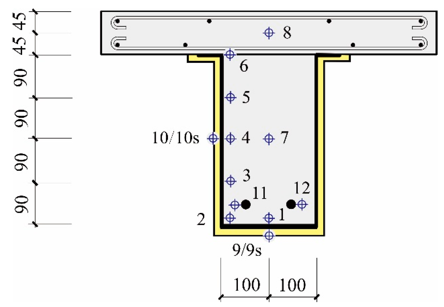
For each specimen, 10 or 12 Type WRNK-101 thermocouples 3 mm in diameter were embedded in the cross section 550 mm away from the support (see Figure 8). Thermocouples 1–6 were used to measure the temperatures at different positions on the surface of the in-filled concrete. Although the end faces of Thermocouples 1–6 were in touch with the inner surface of the U-shaped steel at first, they separated from the steel when the bond between the in-filled concrete and the steel was destroyed during the test. Thermocouples 9 and 10 were employed to measure the temperatures of the bottom flange and the web of the U-shaped steel, respectively. Thermocouples 7 and 8 were adopted to record the temperatures at the center of in-filled concrete and at the center of the slab. For Specimens B2 and B4, Thermocouples 11 and 12 were used to measure the temperatures of the longitudinal reinforcements. The front parts of Thermocouples 9 and 10 in Specimens 1–5 were parallel to the outer surface of the U-shaped steel, which means their end faces were not completely in touch with the steel. The temperatures at a position 3 mm away from the steel surface were actually recorded. To measure the temperature of the U-shaped steel exactly, two additional thermocouples (Thermocouples 9s and 10s) were embedded in Specimens B5. The front parts of the two additional thermocouples were perpendicular to the outer surface of the U-shaped steel, so their end faces were completely touching the steel.
3. Test Results and Discussions
3.1. Test Observation
Generally speaking, the failure of the specimens containing DCLs and FC resembled that of the reference specimens containing FC alone. After 10 to 20 min of heating, steam was observed rising from the top of the specimens and from the interface between the U-shaped steel and the in-filled concrete at both ends of the specimens. The steam flow lasted until about 95 min. In most of the testing time, the mid-span deflection of the specimens increased slowly but it began to increase quickly as the heating time approached the fire resistance of the specimens. Figure 9 shows the specimens after the fire tests. It can be seen that all the tested specimens exhibited the same failure pattern (i.e., flexural failure).
After the fire test, no specimen showed any obvious slip at the interface between the U-shaped steel and the in-filled concrete at either end of the beam. This is quite different from some reported observations of simply-supported U-shaped steel beams filled with DCLs and FC subjected to two concentrated loadings at room temperature [19]. In those tests, a significant slip was observed at the interface between the U-shaped steel and in-filled concrete in the later stage of loading. This discrepancy probably arises because the modulus of elasticity of the steel decreases remarkably with a rising temperature, which facilitates its elongation when subjected to fire and loading.
After the fire test, when the specimens were taken out from the furnace chamber, small cracks could be observed on the bottom and side surfaces of the concrete slabs, but almost no spalling of the concrete was observed due to normal-strength concrete being employed in this study.
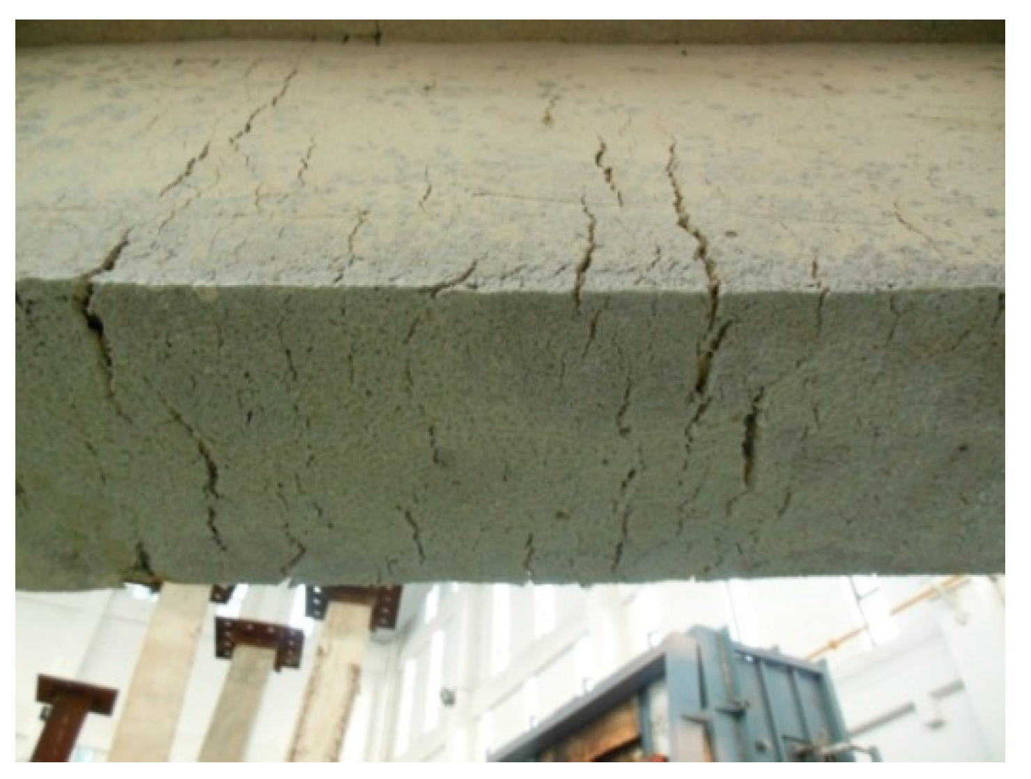
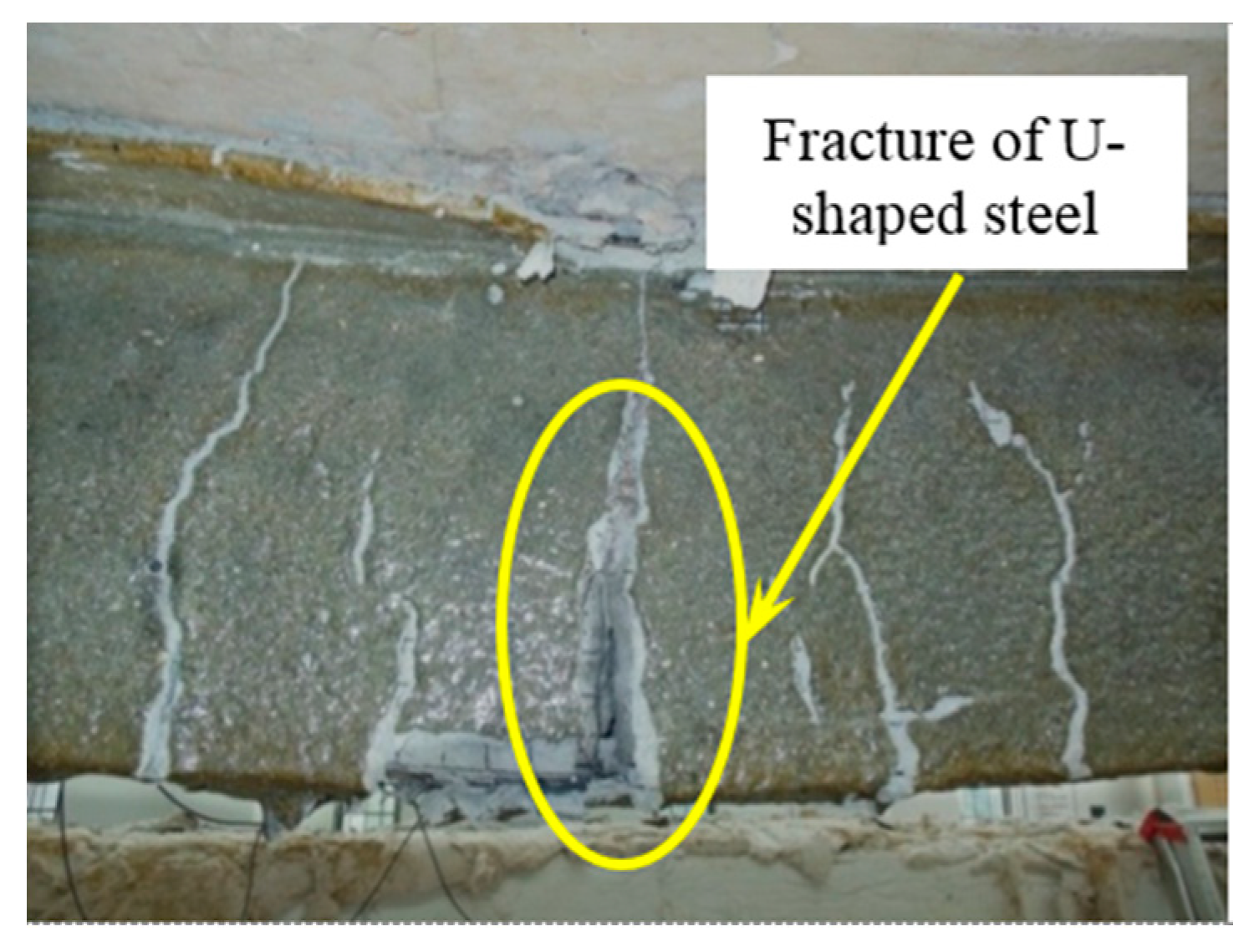
Although many cracks appeared on the surface of the fire-retardant coating, the insulation generally remained intact after the fire tests (see Figure 10). Fracture of the bottom flange and two webs of the U-shaped steel was observed in Specimen B5 (see Figure 11), but it was not observed in any other specimen. The load ratio of Specimen B5 was much higher than that of the others (see Table 1) and no longitudinal reinforcement was embedded in the lower part of the beam.
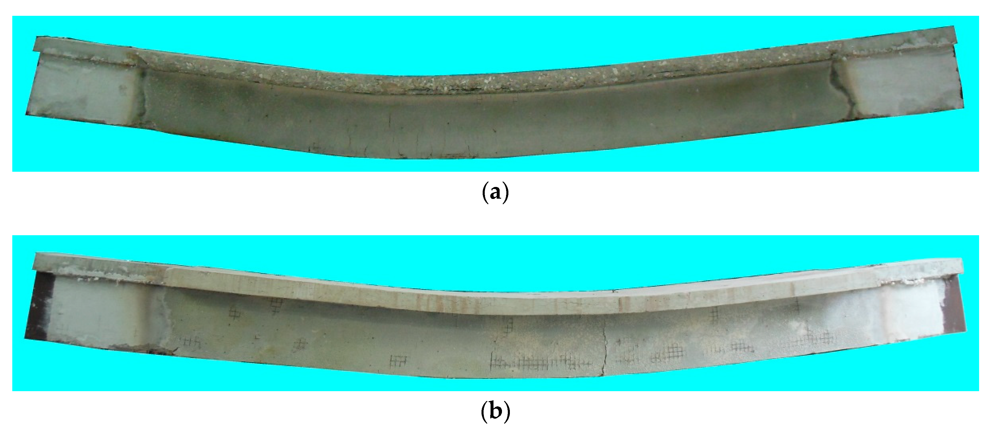
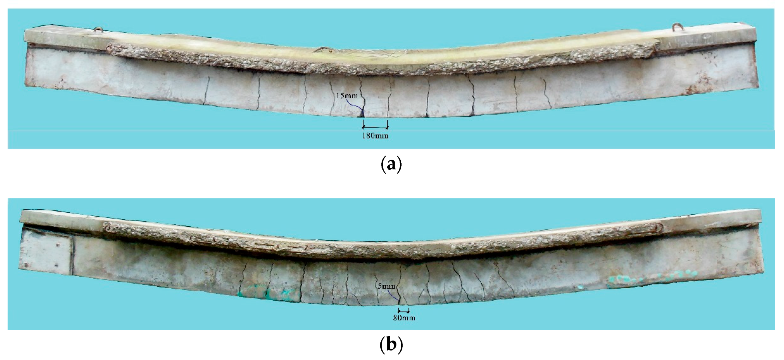
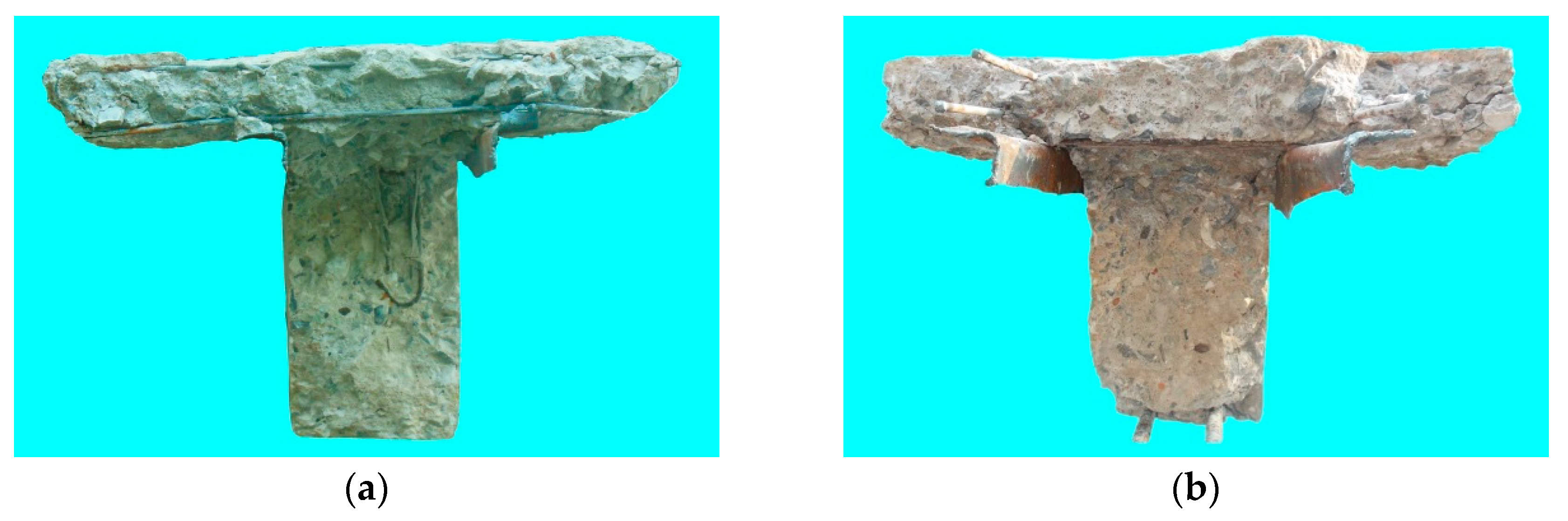
Figure 12 shows the surfaces of the in-filled concrete of Specimens B3 and B4 after the U-shaped steel has been removed. The cut sections of the in-filled concrete are shown in Figure 13. It can be seen that:
- (a).
- The surface of the in-filled concrete is smooth and there are no obvious defects such as voids, holes, or pits on the surfaces or in the cut sections. This indicates that satisfactory construction quality can be achieved using the aforementioned concrete pouring method (all of the DCLs are put into the U-shaped steel at the same time and then the fresh concrete is poured with a continuous vibration).
- (b).
- The flexural cracks propagate from the bottom of the beam to the slab. The minimum crack spacing and the maximum crack width of Specimen B3 are 180 mm and 15 mm, respectively. Specimen B4 shows more and narrower cracks due to the presence of the longitudinal reinforcements in the lower part of the beam. Its minimum crack spacing is 80 mm and the maximum crack width of Specimen B4 is 5 mm.
- (c).
- The cut sections of the in-filled concrete show that the DCLs and the FC bond well, which makes them work together.
3.2. Thermal Response
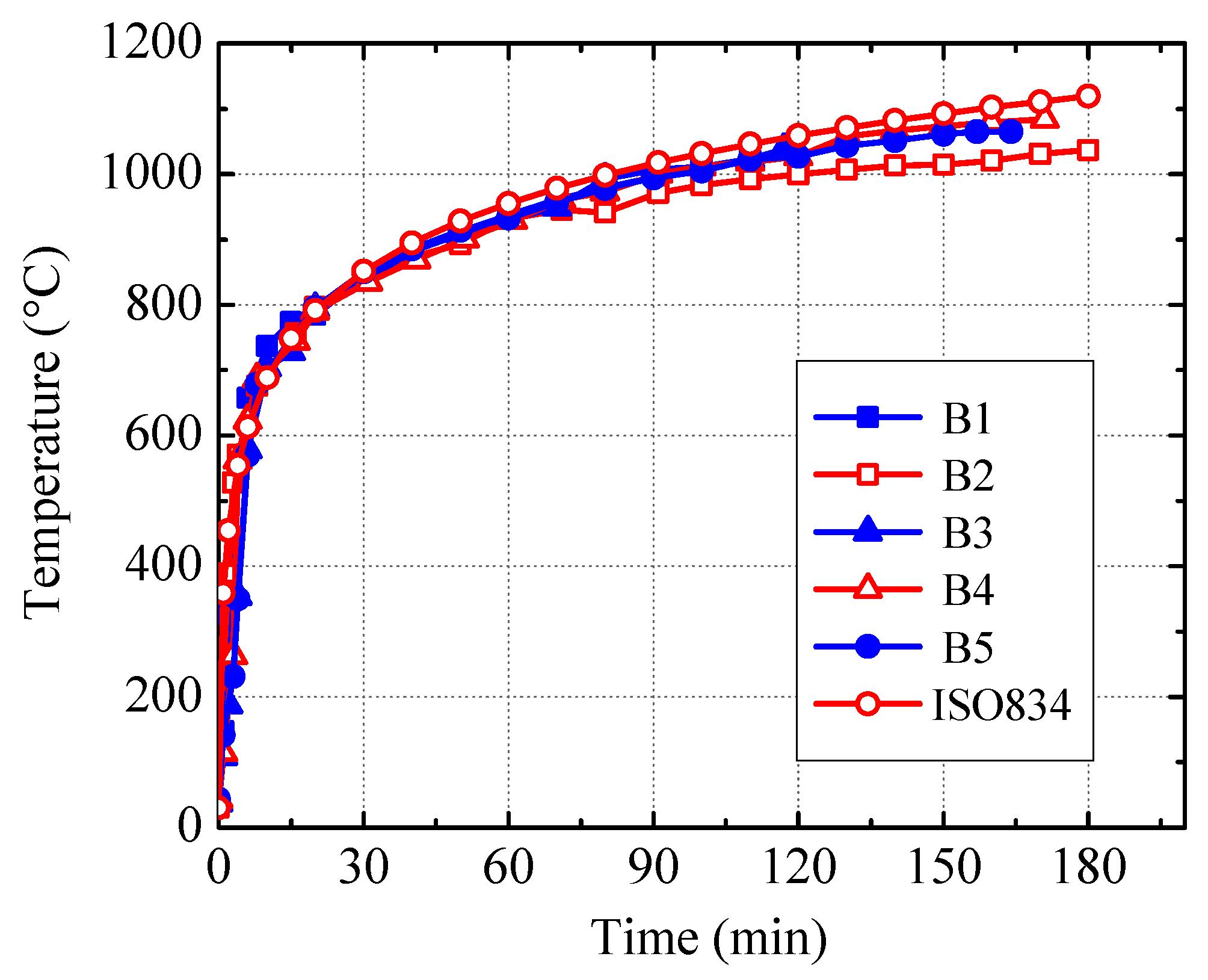
The measured temperature-time curves in the furnace chamber for Specimens B1–B5 are shown in Figure 14. It can be seen from this figure that the recorded curves are generally in good agreement with the ISO834 standard temperature-time curve.
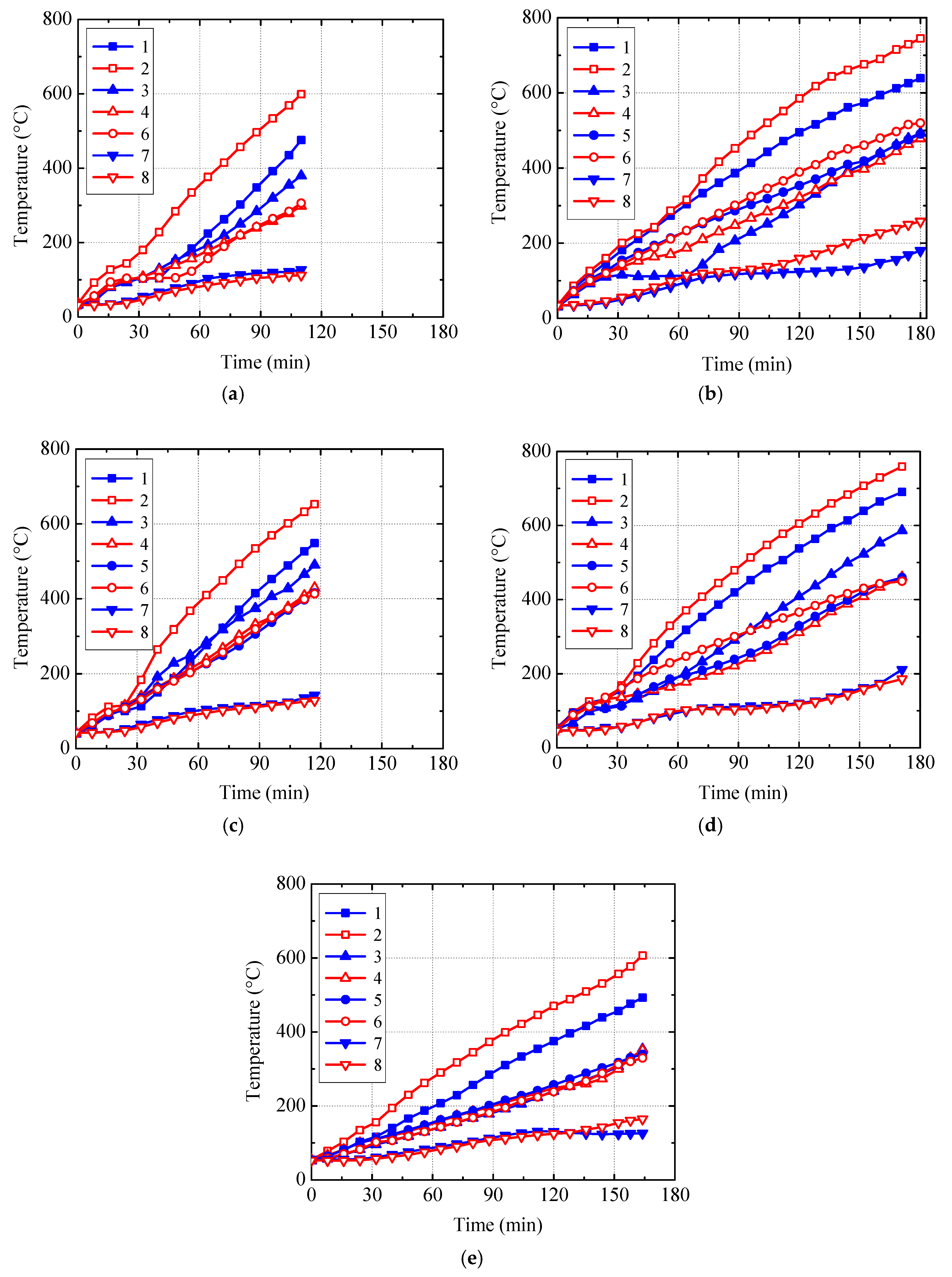
Figure 15 shows the temperature-time curves recorded from Thermocouples 1–8 in Specimens B1~B5. No data were recorded by Thermocouple 5 in Specimens B1 due to accidental damage. It can be seen from Figure 15 that:
- (a).
- The temperature-time curve related to Thermocouple 2, which was located at the corner of the in-filled concrete and subjected to 2-face heating, is generally higher than the others.
- (b).
- During the middle and later stages of the fire test, the temperature-time curve related to Thermocouple 1 located on the bottom surface of the in-filled concrete is generally higher than the curves of Thermocouples 3–6 located on the side surface. Heating from both sides of the beam raised the temperature of Thermocouple 1 relatively quickly.
- (c).
- The temperatures recorded by Thermocouples 4–6 are close to each other on the whole. Temperature differences between Thermocouples 2 and 4 vary between 200 °C and 300 °C in the later stage of the fire test, which indicates distinct temperature differences between different points on the surface of the in-filled concrete.
- (d).
- The temperatures measured by Thermocouples 7 and 8 (located at the center of the in-filled concrete and the center of the slab, respectively) are generally close to each other and increase slowly as the time goes on.
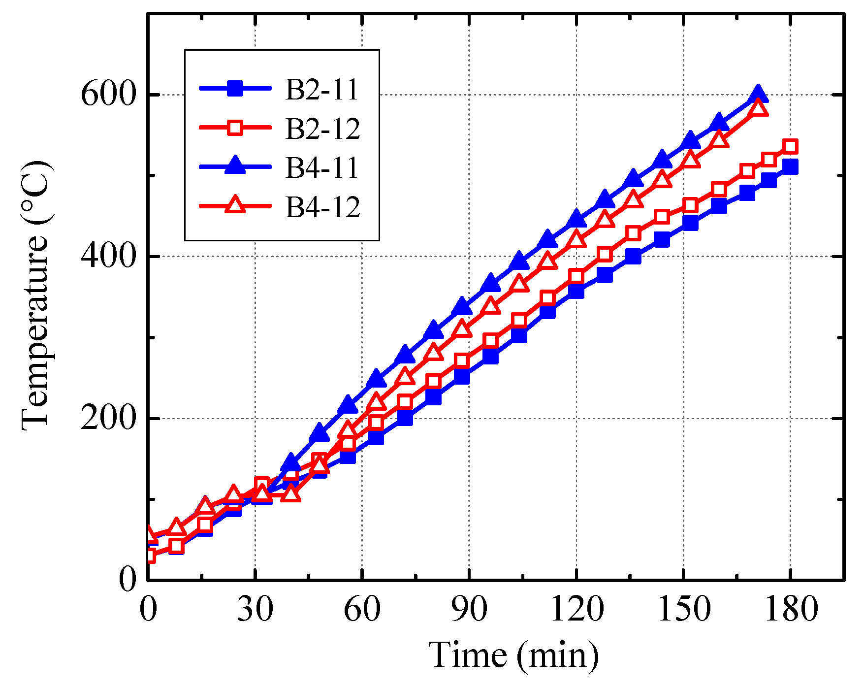
Figure 16 presents the measured temperature-time curves for Thermocouples 11 and 12 in Specimens B2 and B4. From the figure, it can be concluded that:
- (a).
- The measured temperatures for Specimen B2 are lower than those for Specimen B4 because the temperature in the furnace chamber is lower for Specimen B2, which is shown in Figure 14.
- (b).
- Referring to Figure 15d, in the later stages of the fire test, the temperatures recorded by Thermocouples 11 and 12 in Specimen B4 are lower than those of Thermocouples 1 and 2 located at the corner and bottom surface of the in-filled concrete. They are close to that of Thermocouple 3 located at the lower part of the side surface of the in-filled concrete and higher than those of Thermocouples 4–6 located at the upper part of the side surface.
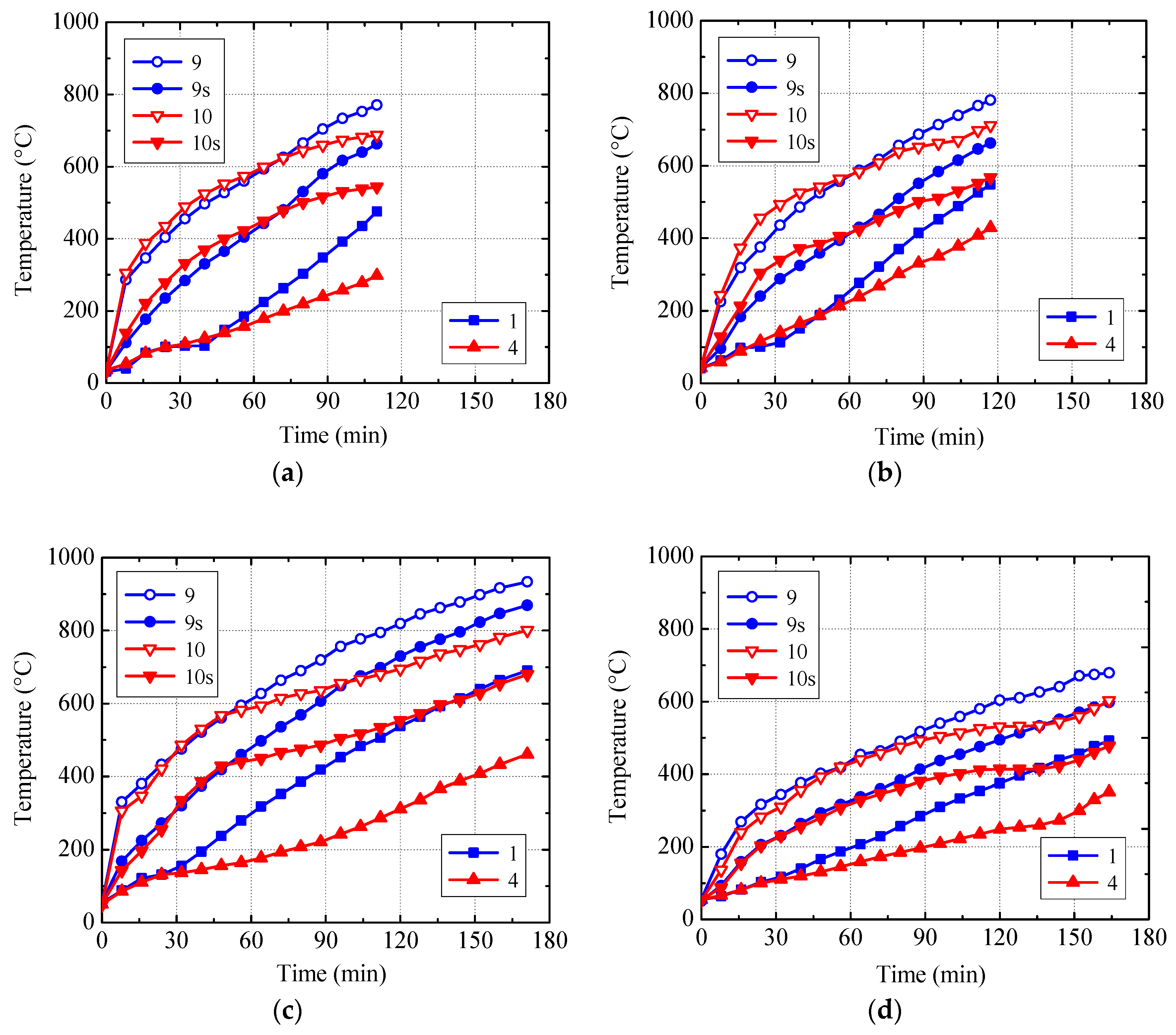
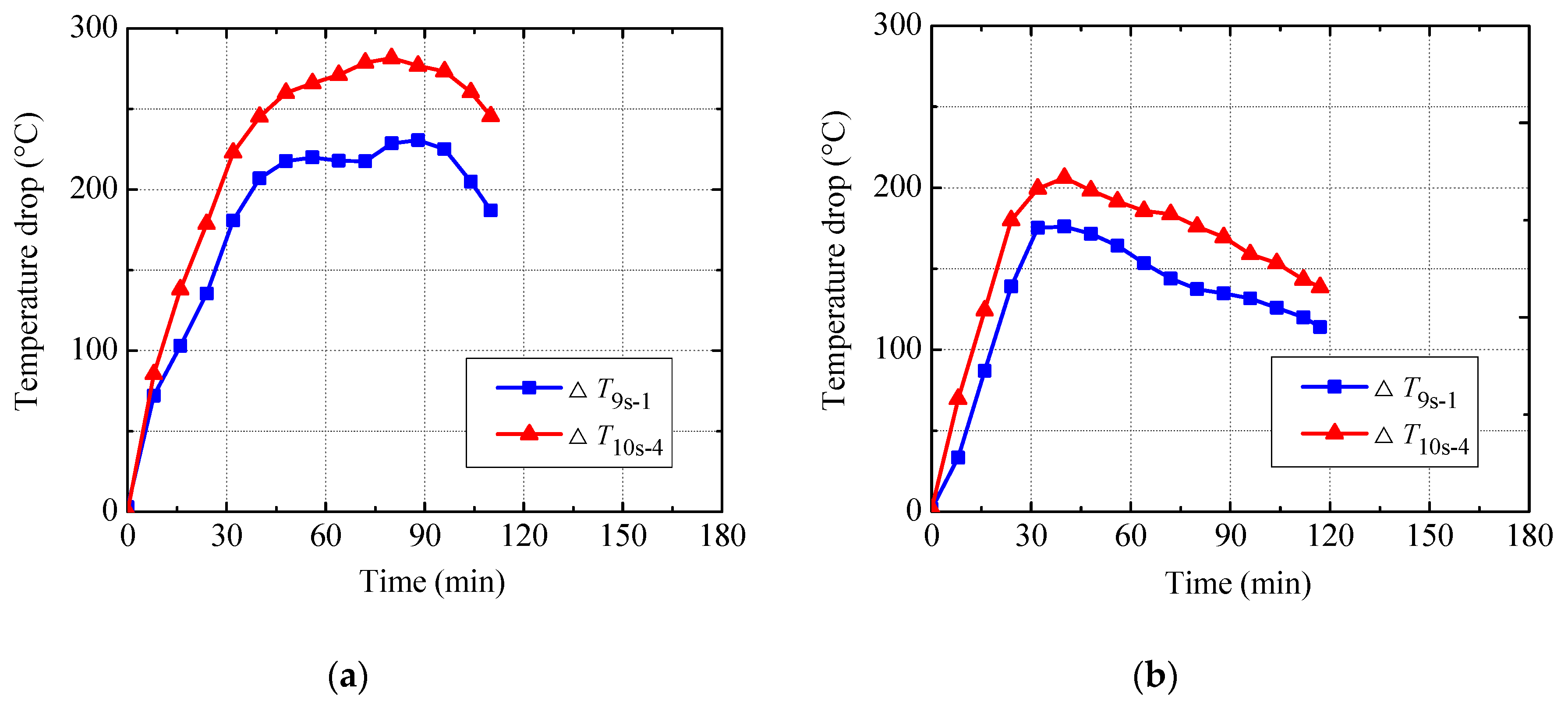
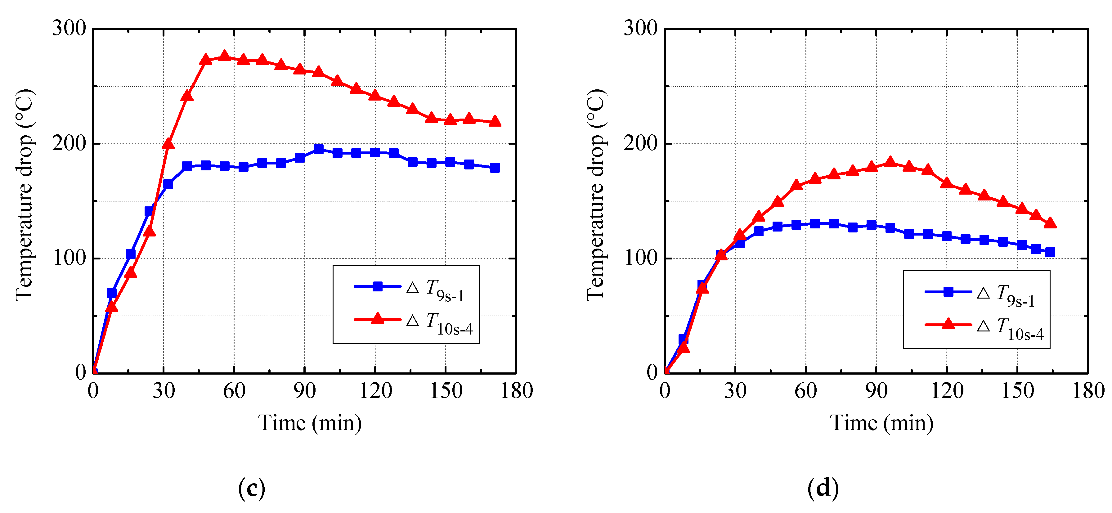
The temperature-time curves of Thermocouples 1, 4, 9s, 10s, 9, and 10 are plotted in Figure 17. The temperature drop between Thermocouples 9s and 1 (i.e., ∆T9s-1), and that between Thermocouples 10s and 4 (i.e., ∆T10s-4) are shown in Figure 18. As mentioned above, Thermocouples 9s and 10s were embedded only in Specimen B5, so for the other specimens the temperatures related to Thermocouples 9s and 10s (i.e., the temperatures on the inner surface of fire-retardant coating) are estimated values. They are interpolated using the measured temperature in the furnace chamber (approximately the temperature of the outer surface of fire-retardant coating), the temperature recorded by Thermocouple 9 or 10 (i.e., the temperature 3 mm away from the inner surface of the fire insulation), and the assumption that the temperature is linearly distributed through the thickness of the insulation. The assumption is supported to some extent by the test data of Specimens B5, which is shown in Figure 19. It can be seen from Figure 17 and Figure 18 that:
- (a).
- For Specimen B5, the measured temperatures pertaining to Thermocouples 9 or 10 are, respectively, higher than those related to Thermocouples 9s and 10s and the temperature difference between Thermocouple 9 (or 10) and Thermocouple 9s (or 10s) fluctuates between 80 °C and 125 °C. Therefore, to accurately measure the temperature of steel protected by the fire-retardant coating, the front part of the thermocouple should be perpendicular to the surface of the steel and their end face should be completely in touch with the steel.
- (b).
- Since the actual thickness of the U-shaped steel is only 2.4 mm and the thermal conductivity of the steel is high, the temperatures recorded by Thermocouples 9s and 10s may be regarded as the temperatures of the inner surface of the steel. So there are remarkable temperature drops (i.e., ∆T9s-1 and ∆T10s-4) at the interface between the U-shaped steel and the in-filled concrete. This may be due to the gap between them induced by the loading and heating. The thermal conductivity of the air and water vapor in the gap is significantly lower than that of the steel and concrete, which impedes the heat flow from the steel to the in-filled concrete to some extent.
- (c).
- With the increasing of the heating time, the temperature drop at the steel-concrete interface (i.e., ∆T9s-1 and ∆T10s-4) increases at first and then decreases gradually. For Specimens B1, B3, and B4 with a fire insulation thickness of 10 mm, the peak values of ∆T9s-1 vary between 175 °C and 230 °C, and the peak values of ∆T10s-4 range from 205 °C to 280 °C. However, for Specimen B5 with a fire insulation thickness of 18 mm, the peak values of ∆T9s-1 and ∆T10s-4 are, respectively, 130 °C and 183 °C. Clearly, for any given specimen, the peak value of ∆T10s-4 is higher than that of ∆T9s-1, which implies that the thermal resistance at the interface between the U-shaped steel and the in-filled concrete near the mid-height of the beam is greater than that at the bottom. On the other hand, the temperature drop at the steel-concrete interface decreases with increasing the thickness of the fire insulation.
3.3. Structural Response
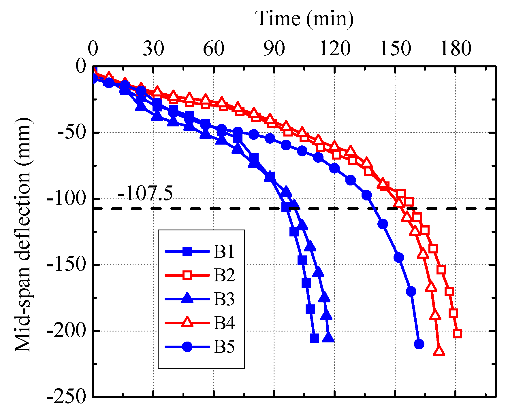
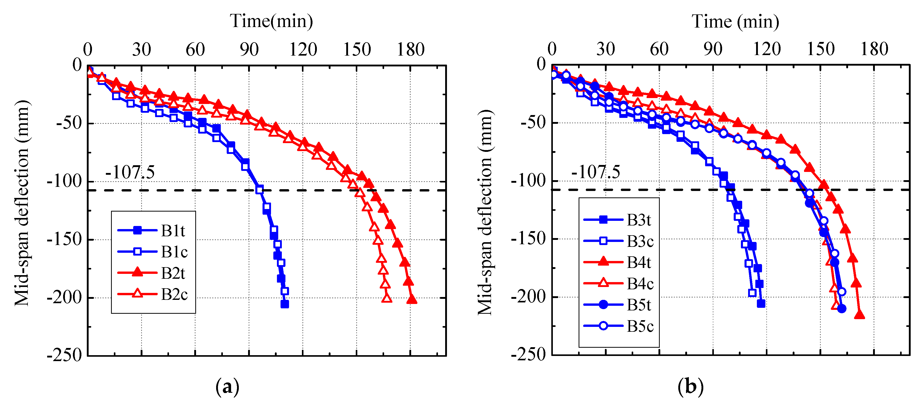
The measured mid-span deflection-time curves of the specimens are shown in Figure 20. The horizontal dashed line in the figure represents the critical mid-span deflection (i.e., 107.5 mm) at which the fire resistance of the specimens reached. It can be concluded that:
- (a).
- The measured mid-span deflection-time curves of the specimens with different replacement ratios of DCLs (i.e., Specimens B1 and B3 and Specimens B2 and B4) are close to each other, which implies that using DCLs has almost no influence on the fire-induced deformation.
- (b).
- When the load ratio and the thickness of the fire insulation are the same, the mid-span deflections of the specimens with longitudinal reinforcements (i.e., Specimens B2 and B4) develop much more slowly than those of the specimens without longitudinal reinforcements (i.e., Specimens B1 and B3) because the mechanical properties of the embedded longitudinal reinforcements degrade more slowly than those of the U-shaped steel.
- (c).
- For Specimens B2, B4, and B5 with the same applied load, the development of the mid-span deflections of the former two with longitudinal reinforcements and an insulation thickness of 10 mm is slightly slower than that of the latter one without longitudinal reinforcements and having an insulation thickness of 18 mm.
3.4. Fire Resistance
The measured fire resistance of the specimens is listed in Table 1. It can be seen that:
- (a).
- The fire resistance of Specimen B1 (or B2) is very close to that of Specimen B3 (or B4), which indicates that the replacement ratio of DCLs within a range of 0% to 33% has a very limited effect on the fire resistance of the specimens.
- (b).
- With the same load ratio and insulation thickness, the fire resistance of Specimen B2 (or B4) is about 50% longer than that of Specimen B1 (or B3), which implies that embedding longitudinal reinforcements increases the fire resistance significantly.
- (c).
- Although Specimens B2, B4, and B5 were subjected to the same applied load, the former two exhibit longer fire resistance than the latter one, which indicates that embedding longitudinal reinforcements (2φ18) is more effective in improving fire resistance than increasing insulation thickness from 10 mm to 18 mm.
- (d).
- When the actual load ratio is 0.45 and the insulation thickness is 10 mm, the beams without longitudinal reinforcements and with a longitudinal reinforcement ratio of 0.7% can meet the requirements of fire resistance classes R90 and R120, respectively. At the same time, the beam without longitudinal reinforcements and with an insulation thickness of 18 mm can satisfy the requirements of fire resistance class R120 at an actual load ratio of 0.625.
4. Numerical Study
The SAFIR software, developed at the University of Liege, Liege, Belgium, has been widely used to analyze the behavior of structures in fire [30,31]. It is used to set up finite-element models to predict the thermal and structural responses of the U-shaped steel beams filled with DCLs and FC exposed to fire. Thermal analysis is performed prior to structural analysis to obtain the thermal profiles of such beams. Their structural behavior in fire is then simulated.
4.1. Finite-Element Models
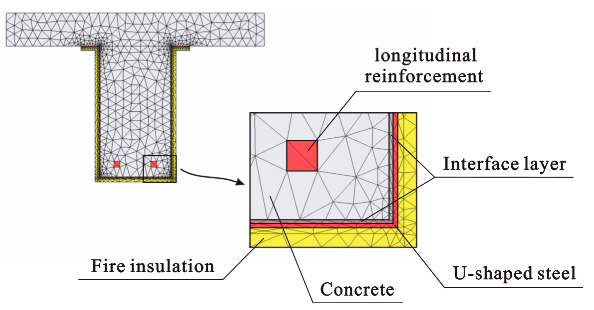
The temperature distribution along the length of the beam is assumed to be uniform. Therefore, a plane model, as shown in Figure 21, is employed in the thermal analysis. This plane section (including the U-shaped steel, in-filled concrete, fire-retardant coating, and longitudinal reinforcements) is discretized by many triangular elements. In this model, to take the effect of interface thermal resistance into account, a thin interface layer is assumed to exist between the U-shaped steel and the in-filled concrete. In order to enhance the compatibility of the element meshes, the thickness of the interface layer is assumed to be 2 mm. The outer surface of the U-shaped steel is coated by fire-retardant coating. The bottom and side surfaces of the beam and the soffit of the slab are exposed to the fire with the heating process shown in Figure 14. The convective heat transfer coefficients are 25 W/m2 K for the surfaces exposed to fire and 9 W/m2 K for the unheated top surface of the slab. The thermal emissivity of the surface of concrete is 0.56 and the surface of fire insulation is 0.496 [32].
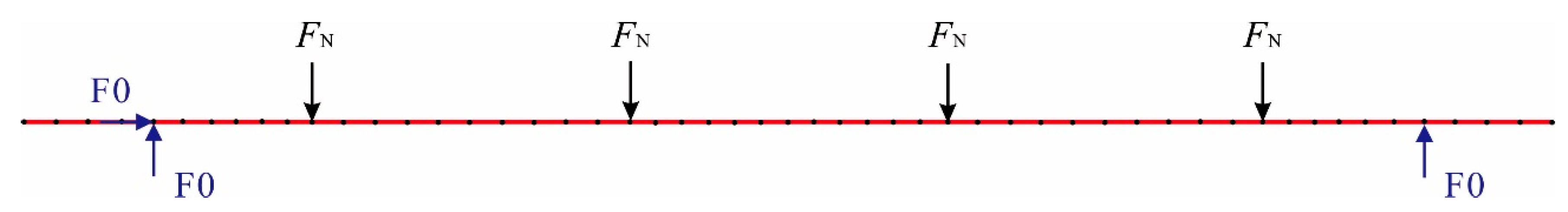
Figure 22 shows the finite-element model for the structural analysis. The beam elements provided by the SAFIR software are adopted in this model. The discretization of the cross section of the beam for structural analysis is the same as that for thermal analysis. There are two options to model the interaction between the U-shaped steel and the in-filled concrete. First, the bond between the steel and concrete is considered perfect and no slip occurs, which was employed in past research [33,34,35]. Second, the interaction between the steel and concrete is simulated by using spring elements and contact elements [36,37]. According to the above-mentioned test observation (see Section 3.1), the slip between the U-shaped steel and the in-filled concrete can be neglected approximately, thus the first option is adopted in this study. In Figure 22, the vertical load FN is that applied to the beam during the fire test and “F0” indicates that the displacement of the node along the arrow is fully constrained.
SAFIR uses an iterative procedure to converge on the correct solution for each increment. In this study, a tolerance value of 0.001 is adopted during the calculations. The failure limit state (i.e., the state at which the beam’s fire resistance is reached) used for the structural analysis is the same as that for the fire test, which has been given in Section 2.2.
4.2. Thermal and Mechanical Properties
Variations of the thermal and mechanical properties of the U-shaped steel and longitudinal reinforcements (including density, specific heat, thermal conductivity, thermal strain, and stress-strain relationship) with temperature are determined, according to Eurocode 4 [38]. The elastic modulus of the U-shaped steel and longitudinal reinforcements at room temperature is taken as 2.1 × 10⁵ MPa. The yield strengths of the U-shaped steel and longitudinal reinforcements listed in Table 1 are employed in the structural analysis. The thermal properties of the demolished concrete are assumed to be the same as those of the fresh concrete and are determined in accordance with Eurocode 2 [39]. The upper limit of concrete thermal conductivity given in Eurocode 2 is adopted and the moisture content of the concrete is taken as 5% by weight. The density of concrete at room temperature is taken as 2400 kg/m3. During the structural analysis, the in-filled concrete composed of DCLs and FC is considered as a whole and the combined compressive strength (fcu, com) of the in-filled concrete is calculated based on Equation (1) [24]. The stress-strain relationship of the in-filled concrete at an elevated temperature is determined according to Eurocode 2. The thermal strain of concrete with siliceous aggregates given in Eurocode 2 is employed.
fcu, com = fcu, old × η + fcu, new × (1 − η)
Due to a lack of information about the density and specific heat of the fire insulation at a high temperature, the room temperature density is adopted in the numerical analysis and the specific heat is taken as 1047 J/(kg °C) [40]. The thermal conductivity of the insulation generally increases as the temperature rises and a rate of increase ranging from about 0.0001 W/m K2 to 0.0003 W/m K2 has been recommended by other researchers [41,42]. In this way, based on the aforementioned value pertaining to room temperature, the thermal conductivity of the fire insulation at an elevated temperature (T) is determined, according to Equation (2).
Tao and Ghannam [27] have investigated the influence of thermal resistance at the steel tube-concrete interface on the temperature distribution of the concrete-filled steel tubular columns and constant values of 0.026 m2 K/W and 0.022 m2 K/W were, respectively, suggested for the interface thermal resistance of the circular and rectangular columns with a cross-sectional size above 300 mm. The loading pattern of the U-shaped steel beams filled with DCLs and FC is completely different from that of the concrete-filled steel tubes, which means the values of interface thermal resistance for the columns may be not suitable for the beams. Through trial-and-error, the thermal resistance at the interface between the web of the U-shaped steel and the in-filled concrete is estimated as 0.03 m2 K/W and that at the interface between the bottom flange of the U-shaped steel and the in-filled concrete is estimated to be 0.02 m2 K/W. It should be noted that the thermal resistance at the steel-concrete interface is expressed as ti/λi where ti is the thickness of the putative interface layer between the steel and the in-filled concrete (assumed to be 2 mm) and λi is the thermal conductivity of the interface layer. During the thermal analysis, the density and specific heat of the interface layer are ignored [43].
4.3. Simulation Results and Discussions
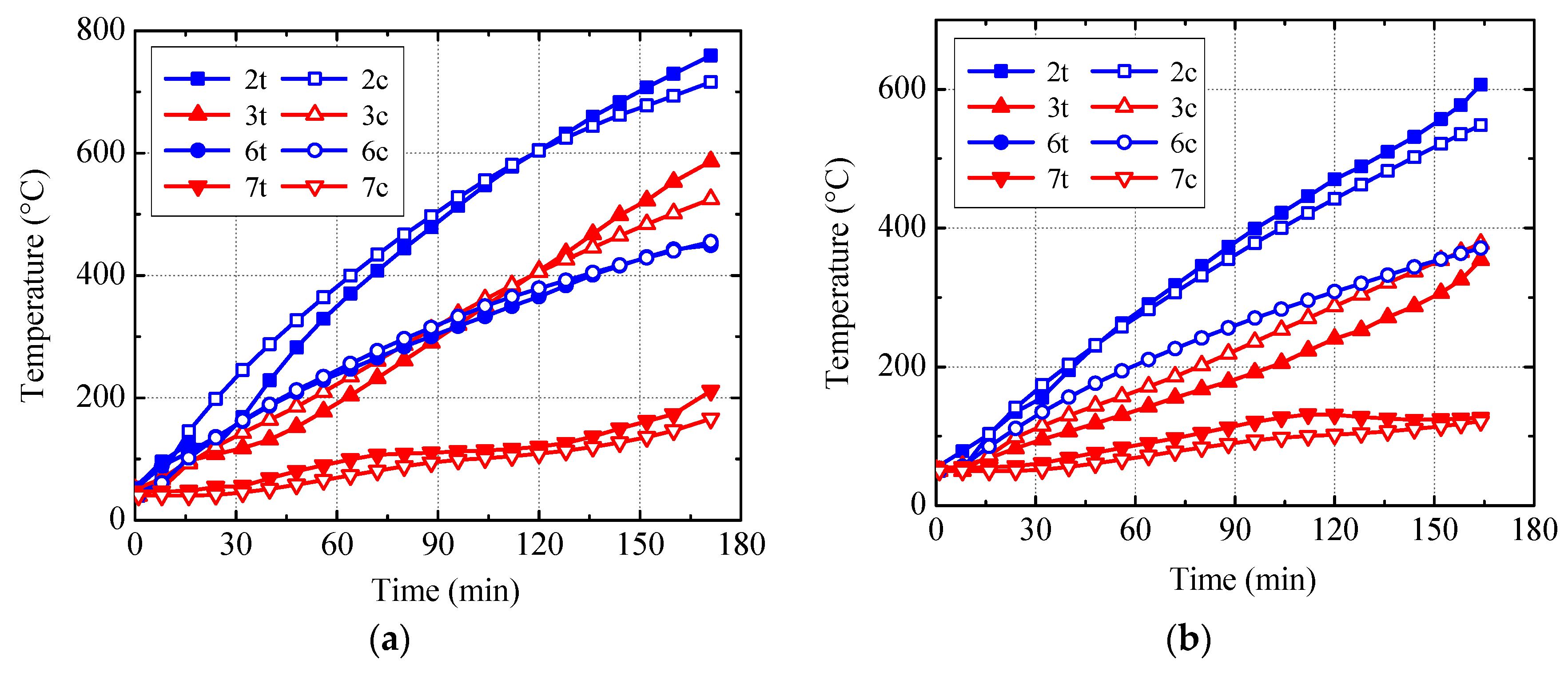
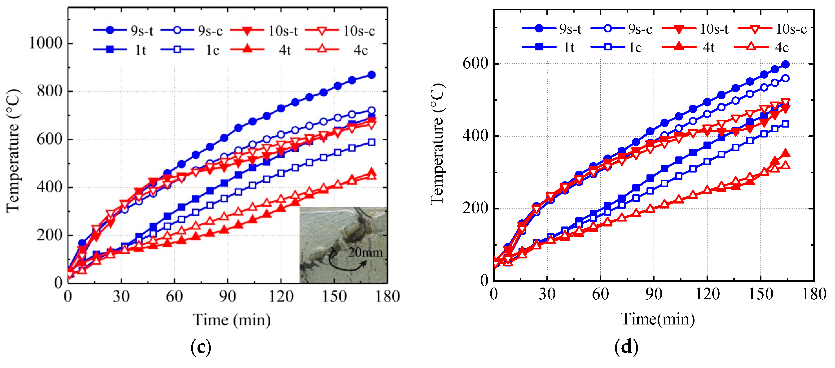
The calculated and measured temperature-time curves for Specimens B4 and B5 are compared in Figure 23 in which “t” and “c” indicate the test and calculated results, respectively. It can be seen that the simulation results generally agree well with the test results except for Points 9s and 1 in Specimen B4. After the fire test, a 20 mm-wide crack was observed in the fire insulation of Specimen B4 near Points 9s and 1 (see Figure 23c), which may explain the relatively large difference between the calculated and measured temperatures.
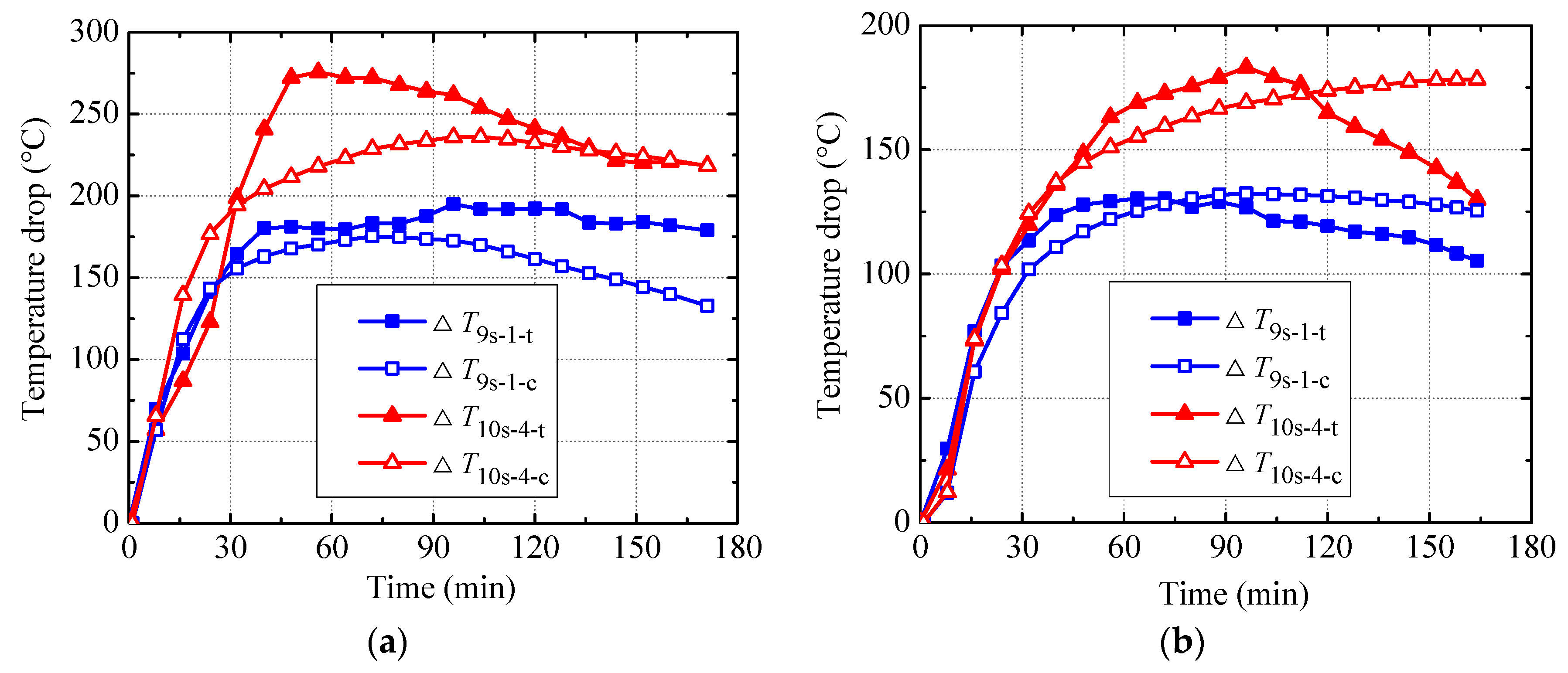
The calculated and measured temperature drop-time curves are compared in Figure 24. For Specimen B4, the peak values of ∆T9s-1-t, ∆T9s-1-c, ∆T10s-4-t, and ∆T10s-4-c are, respectively, 192 °C, 175 °C, 275 °C, and 236 °C. For Specimens B5, the peak values of ∆T9s-1-t, ∆T9s-1-c, ∆T10s-4-t, and ∆T10s-4-c are, respectively, 130 °C, 132 °C, 183 °C, and 178 °C. This indicates that the calculated peak values are generally in good agreement with the measured ones even though the difference between the calculated and measured temperature drop-time curves is relatively large in part of the heating stage.
The calculated and measured mid-span deflection-time curves are compared in Figure 25. It can be seen from this figure that the calculated curves generally agree well with the measured ones. However, for the specimens with longitudinal reinforcements (i.e., Specimen B2 and B4), the difference between the calculated and measured curves is relatively more distinct. This may be due to the fact that the strain-hardening of the longitudinal reinforcements with relatively lower temperature than the U-shaped steel is ignored in the structural analysis. The calculated fire endurances of Specimens B1–B5 are, respectively, 96 minutes, 151 minutes, 98 minutes, 142 minutes, and 142 minutes, which generally match well with the measured values in Table 1.
4.4. Effect of Interface Thermal Resistance
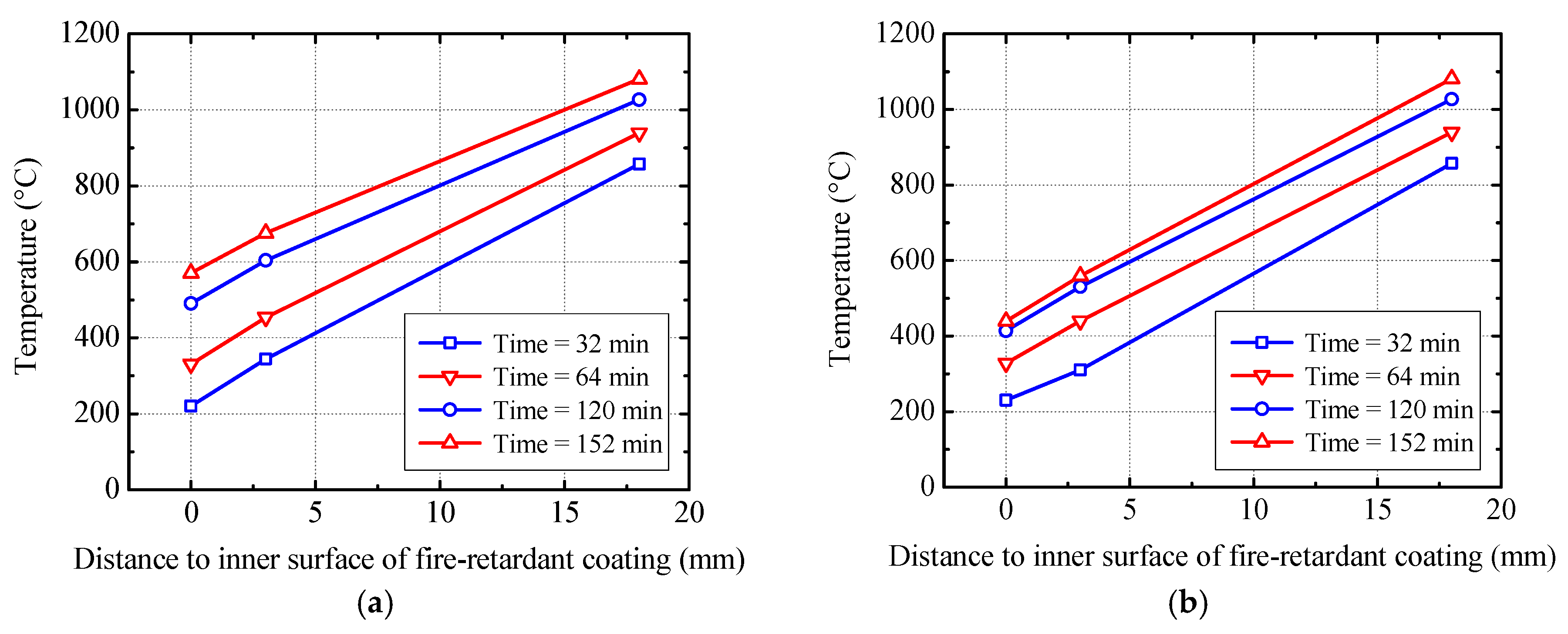
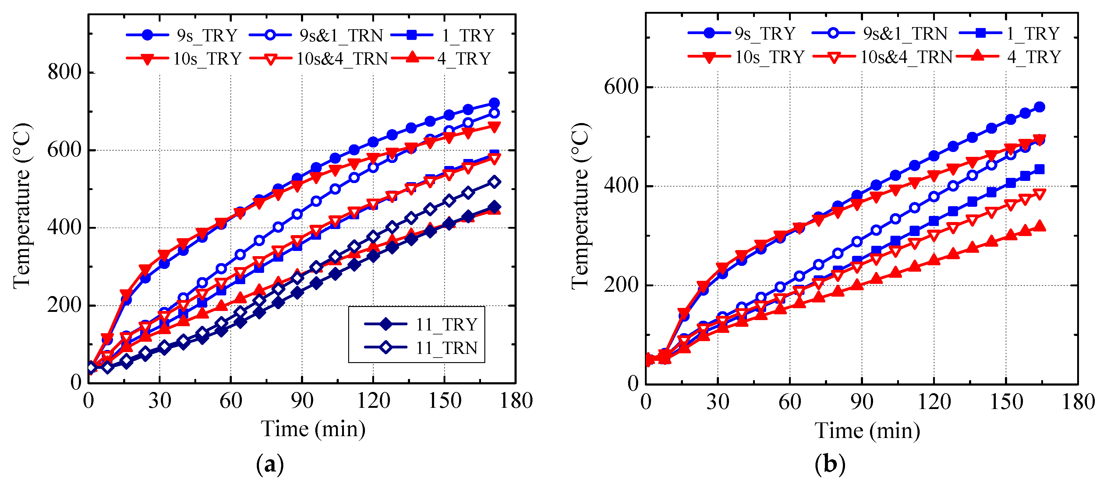
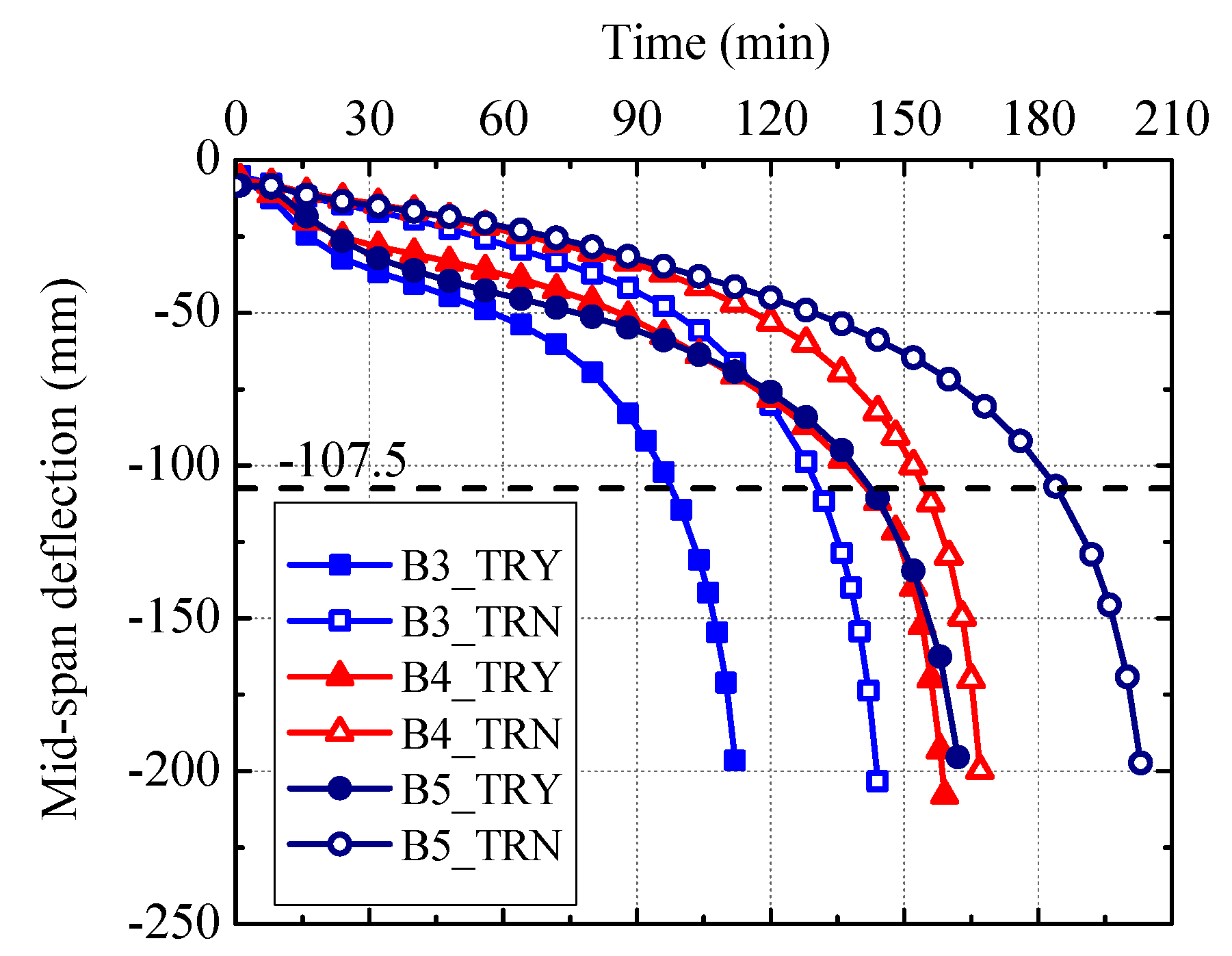
To illustrate the effect of interface thermal resistance on the fire behavior of the U-shaped steel beams filled with DCLs and FC, the calculated results corresponding to the numerical models with and without an interface layer are compared in Figure 26 and Figure 27. In these two figures, “TRY” indicates that the interface thermal resistance is considered whereas “TRN” is not. It can be seen from Figure 26 and Figure 27 that:
- (a).
- In the case that the interface thermal resistance is ignored, the temperatures of the U-shaped steel at Points 9s and 10s are lower than those when considering such thermal resistance, whereas the temperatures of the longitudinal reinforcement (Point 11) and the surface of the in-filled concrete (Points 1 and 4) pertaining to the former case are higher than those corresponding to the latter case. This is because more heat can be transferred into the concrete when such thermal resistance is neglected.
- (b).
- In the case that the interface thermal resistance is ignored, the mid-span deflection of the U-shaped steel beam develops more slowly than that when considering such thermal resistance. This is because the temperature of the U-shaped steel is relatively lower in the former case, which makes the mechanical properties of the steel decrease more slowly with heating time. This phenomenon is especially evident for the beams without longitudinal reinforcements (i.e., Specimens B3 and B5) since the increasing of the longitudinal reinforcements’ temperature may partly offset the beneficial effect of the decreasing of the U-shaped steel’ temperature in the former case.
- (c).
- When the interface thermal resistance is ignored, the calculated fire endurances of Specimens B3–B5 are, respectively, 130 minutes, 154 minutes, and 185 minutes, which are 32%, 8%, and 30% longer than the calculated fire endurances of three specimens when considering such thermal resistance, respectively. Clearly, neglecting the interface thermal resistance will greatly overestimate the fire resistance of the U-shaped steel beams filled with DCLs and FC.
4.5. Parametric Studies
The validated numerical models are employed to investigate the effects of the thickness of fire insulation (t), load ratio (n), and longitudinal reinforcement ratio on the fire resistance of the U-shaped steel beams filled with DCLs and FC. The geometric dimensions of the U-shaped steel and concrete slab, material properties, and boundary conditions of the beams are the same as those of Specimen B3 and remain unchanged in the parametric studies.
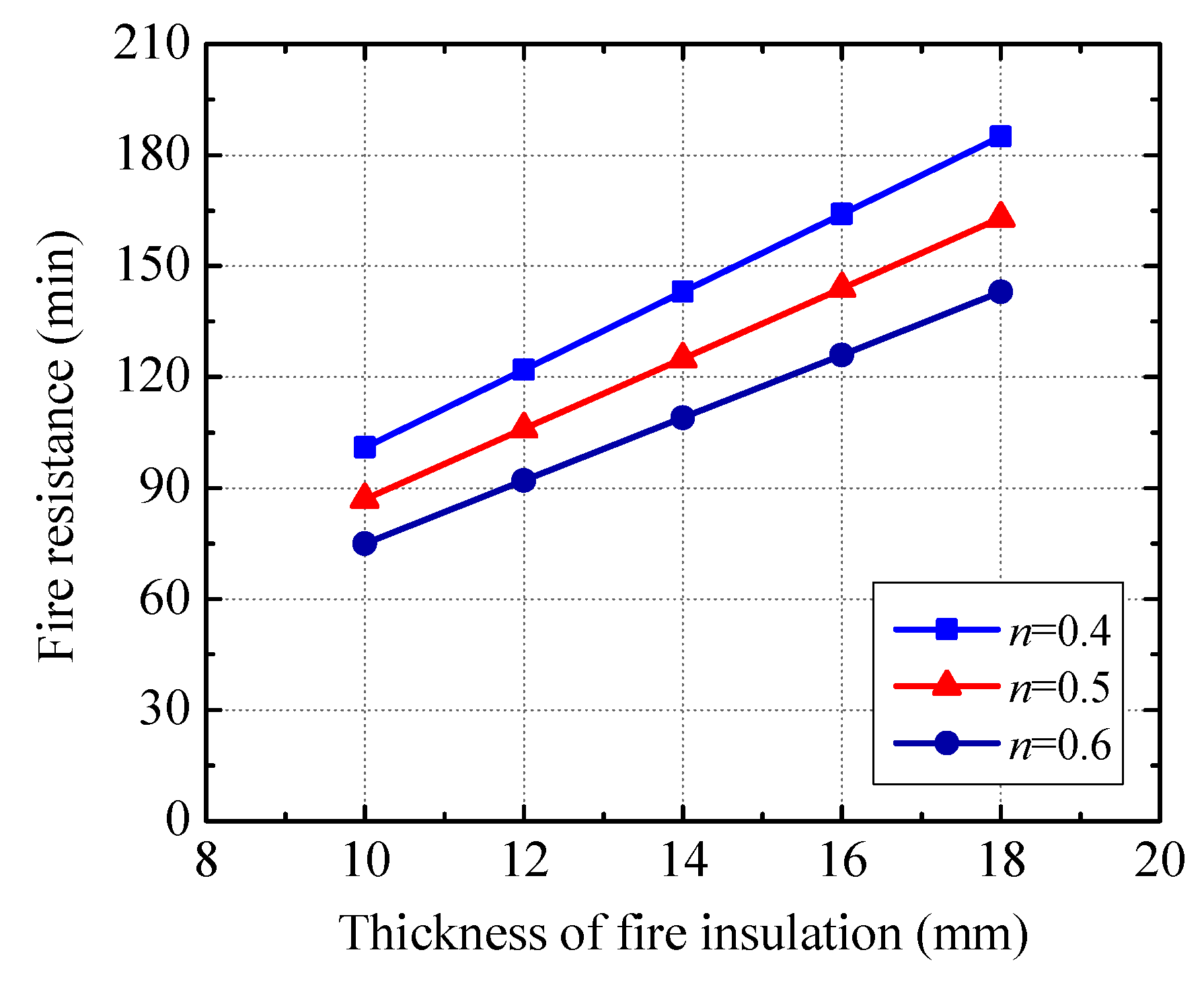
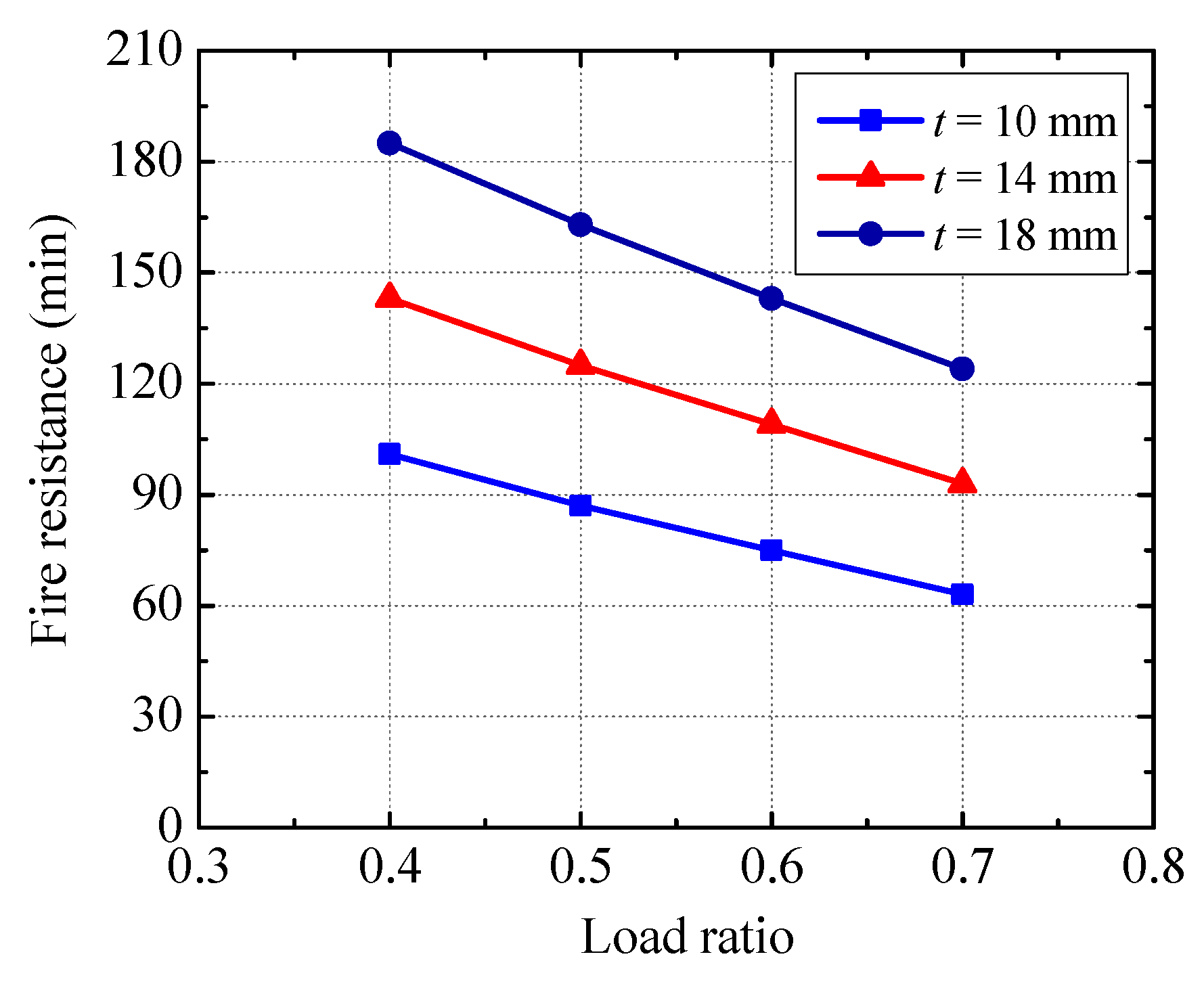
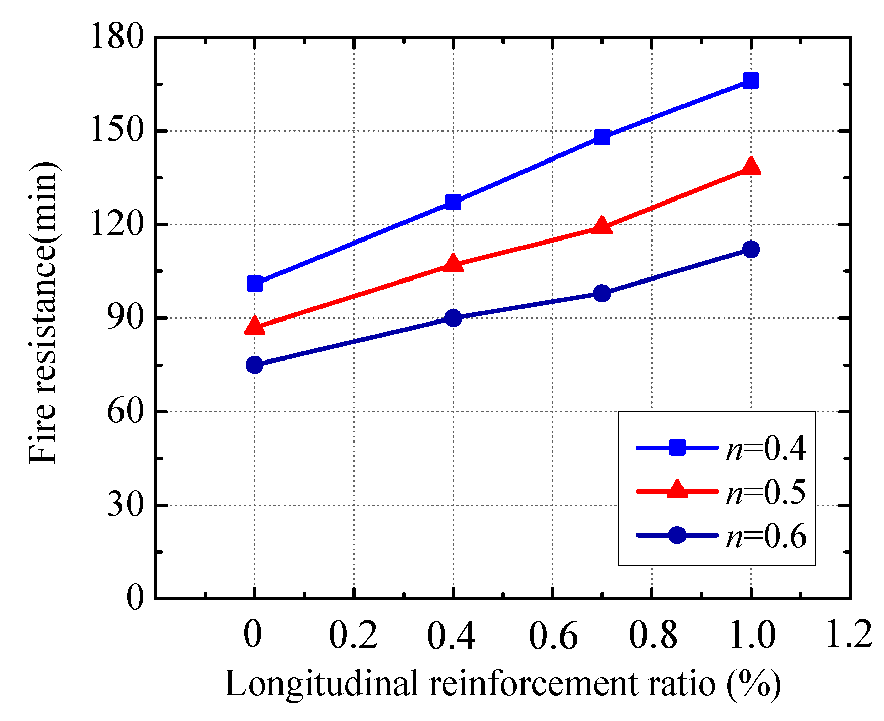
Variations of the beam’s fire resistance with the thickness of fire insulation, load ratio, and longitudinal reinforcement ratio are shown in Figure 28, Figure 29 and Figure 30, respectively. It can be seen from these figures that:
- (a).
- The beam’s fire resistance almost increases linearly with the increasing of the thickness of fire insulation. When the insulation thickness rises from 10 mm to 14 mm (18 mm), the fire endurance enhances by about 43% (87%).
- (b).
- Increasing the load ratio decreases the beam’s fire resistance noticeably. Comparing with the fire endurance related to the load ratio of 0.4, the fire endurances pertaining to the load ratios of 0.5, 0.6, and 0.7 decrease by about 12%, 24% and 35%, respectively.
- (c).
- A significant rise in the beam’s fire resistance can be achieved by increasing the longitudinal reinforcement ratio. For example, at the load ratio of 0.5, raising the longitudinal reinforcement ratio from 0% to 0.4% (0.7%, 1.0%) increases the fire endurance by about 22% (36%, 58%).
5. Conclusions
Fire behavior of the U-shaped steel beams filled with DCLs and FC has been experimentally investigated in this paper and numerical models are developed using SAFIR to determine the thermal and structural responses of the specimens. From the experimental and simulation results, the following conclusions can be drawn:
- (1)
- Fire behavior of the U-shaped steel beam filled with DCLs and FC including failure process, temperature distribution, mid-span deflection, and fire resistance is similar to that of the reference beam filled with FC alone, which implies that using DCLs has a very limited effect on the fire performance.
- (2)
- Satisfactory construction quality can be achieved using the concrete pouring method in this study (i.e., all of the DCLs are put into the U-shaped steel at the same time and then the fresh concrete is poured with a continuous vibration).
- (3)
- The interface thermal resistance between the U-shaped steel and the in-filled concrete near the mid-height of the beam is greater than that at the bottom. The thermal resistance induces a temperature drop of up to 280 °C at the steel-concrete interface. The temperature drop decreases when the thickness of the fire insulation increases.
- (4)
- When the load ratio and the thickness of the fire insulation are the same, the mid-span deflection of the beam with a longitudinal reinforcement ratio of 0.7% develops much more slowly than that of the beam without longitudinal reinforcements and the fire resistance of the former is about 50% longer than that of the latter.
- (5)
- When the actual load ratio is 0.45 and the insulation thickness is 10 mm, the beams without longitudinal reinforcements and with a longitudinal reinforcement ratio of 0.7% can meet the requirements of fire resistance classes R90 and R120, respectively. At the same time, the beam without longitudinal reinforcements and with an insulation thickness of 18 mm can satisfy the requirements of fire resistance class R120 at an actual load ratio of 0.625.
- (6)
- Neglecting the interface thermal resistance between the U-shaped steel and the in-filled concrete will greatly overestimate the fire resistance of the beams. The thermal resistance at the interface between the web of the U-shaped steel and the in-filled concrete is suggested to be 0.03 m2 K/W and at the interface between the bottom flange of the U-shaped steel and the in-filled concrete is recommended to be 0.02 m2 K/W.
It should be noted that some findings mentioned above are only based on the fire tests of five beam specimens and corresponding numerical analysis. More experiments are needed in the future to further improve the aforementioned quantitative values (e.g., thermal resistance at the interface between U-shaped steel and in-filled concrete).
Author Contributions
B.W. and M.J. conceived and designed the experiments. M.J. performed the experiments. B.W. and M.J. analyzed the data and wrote the paper.
Acknowledgments
The authors would like to gratefully acknowledge research grants from the National Key R&D Program of China (grant 2017YFC0803300), the National Natural Science Foundation of China (grants 51438007, 51378225), the Key Project of Science (Technology) Research of Guangzhou (grant 201607020005), and the State Key Laboratory of Subtropical Building Science of China (grants 2018ZC03, 2017KC17, 2015ZB21).
Conflicts of Interest
The authors declare that there is no conflict of interest regarding the publication of this paper.
References
- Oikonomou, N.D. Recycled concrete aggregates. Cem. Concr. Compos. 2005, 27, 315–318. [Google Scholar] [CrossRef]
- Topçu, I.B. Physical and mechanical properties of concretes produced with waste concrete. Cem. Concr. Res. 1997, 27, 1817–1823. [Google Scholar] [CrossRef]
- Shayan, A. Performance and Properties of Structural Concrete Made with Recycled Concrete Aggregate. ACI Mater. J. 2003, 100, 371–380. [Google Scholar]
- Bravo, M.; Brito, J.D.; Evangelista, L. Thermal performance of concrete with recycled aggregates from CDW plants. Appl. Sci. 2017, 7, 740. [Google Scholar] [CrossRef]
- Thomas, C.; Setién, J.; Polanco, J.A.; Alaejos, P.; Juan, M.S.D. Durability of recycled aggregate concrete. Constr. Build. Mater. 2013, 40, 1054–1065. [Google Scholar] [CrossRef]
- Mohamad, N.; Khalifa, H.; Samad, A.A.A.; Mendis, P.; Goh, W.I. Structural performance of recycled aggregate in CSP slab subjected to flexure load. Constr. Build. Mater. 2016, 115, 669–680. [Google Scholar] [CrossRef]
- Kang, H.K.; Kim, W.; Kwak, Y.K.; Hong, S.G. Flexural testing of reinforced concrete beams with recycled concrete aggregates. ACI Struct. J. 2014, 111, 607–616. [Google Scholar] [CrossRef]
- Fathifazl, G.; Razaqpur, A.G.; Isgor, O.B.; Abbas, A.; Fournier, B.; Foo, S. Shear strength of reinforced recycled concrete beams with stirrups. Mag. Concr. Res. 2009, 61, 477–490. [Google Scholar] [CrossRef]
- Choi, W.C.; Yun, H.D. Compressive behavior of reinforced concrete columns with recycled aggregate under uniaxial loading. Eng. Struct. 2012, 41, 285–293. [Google Scholar] [CrossRef]
- Liu, W.C.; Cao, W.L.; Zong, N.N.; Wang, R.W.; Ren, L.L. Experimental study on punching performance of recycled aggregate concrete thin wallboard with single-layer reinforcement. Appl. Sci. 2018, 8, 188. [Google Scholar] [CrossRef]
- Xiao, J.; Sun, Y.; Falkner, H. Seismic performance of frame structures with recycled aggregate concrete. Eng. Struct. 2006, 28, 1–8. [Google Scholar] [CrossRef]
- RILEM TC 121-DRG. Specification for concrete with recycled aggregates. Mater. Struct. 1994, 27, 557–559. [CrossRef]
- ACI Committee 555. Removal and Reuse of Hardened Concrete; ACI 555R-01; American Concrete Institute: Farmington Hills, MI, USA, 2001. [Google Scholar]
- Ministry of Housing and Urban-Rural Development of the People’s Republic of China. Technical Specification for Application of Recycled Aggregate; JGJ/T 240-2011; China Architecture & Building Press: Beijing, China, 2011.
- Wu, B.; Xu, Z.; Ma, Z.J.; Liu, Q.X.; Liu, W. Behavior of reinforced concrete beams filled with demolished concrete lumps. Struct. Eng. Mech. 2011, 40, 411–429. [Google Scholar] [CrossRef]
- Wu, B.; Liu, C.H.; Yang, Y. Size effect on compressive behaviours of normal-strength concrete cubes made from demolished concrete blocks and fresh concrete. Mag. Concr. Res. 2013, 65, 1155–1167. [Google Scholar] [CrossRef]
- Zhao, X.Y.; Wu, B.; Wang, L. Structural response of thin-walled circular steel tubular columns filled with demolished concrete lumps and fresh concrete. Constr. Build. Mater. 2016, 129, 216–242. [Google Scholar] [CrossRef]
- Wu, B.; Zhao, X.Y.; Zhang, J.S. Cyclic behavior of thin-walled square steel tubular columns filled with demolished concrete lumps and fresh concrete. J. Constr. Steel Res. 2012, 77, 69–81. [Google Scholar] [CrossRef]
- Wu, B.; Ji, M.M. Flexural tests on thin-walled U-shaped steel beams filled with demolished concrete blocks and fresh concrete. J. Build. Struct. 2014, 35, 246–254. (In Chinese) [Google Scholar]
- Wu, B.; Liu, C.H.; Liu, Q.X. Tests on seismic behaviors of double thin skin hybrid walls filled with demolished concrete lumps. Key Eng. Mater. 2012, 517, 536–545. [Google Scholar] [CrossRef]
- Wu, B.; Luo, Z.C. Mechanical property of composite slabs with profiled steel sheet casted using demolished concrete blocks and fresh concrete. J. Build. Struct. 2016, 37, 29–38. (In Chinese) [Google Scholar]
- Wu, B.; Duan, J.; Wen, B. Preparations of new fireproof coating and fire-resistance tests on composite slabs filled with demolished concrete blocks and fresh concrete. China Civ. Eng. J. 2014, 47, 82–92. (In Chinese) [Google Scholar]
- Teng, J.G.; Zhao, J.L.; Yu, T.; Li, L.J.; Guo, Y.C. Behavior of FRP-confined compound concrete containing recycled concrete lumps. J. Compos. Constr. 2016, 20, 1–13. [Google Scholar] [CrossRef]
- Wu, B.; Ji, M.M.; Zhao, X.Y. State-of-the-art of recycled mixed concrete (RMC) and composite structural members made of RMC. Eng. Mech. 2016, 33, 1–10. (In Chinese) [Google Scholar]
- Wu, B.; Yu, Y.; Chen, Z. Compressive Behaviors of Prisms Made of Demolished Concrete Lumps and Fresh Concrete. Appl. Sci. 2018, 8, 743. [Google Scholar] [CrossRef]
- Ding, J.; Wang, Y.C. Realistic modelling of thermal and structural behaviour of unprotected concrete filled tubular columns in fire. J. Constr. Steel Res. 2008, 64, 1086–1102. [Google Scholar] [CrossRef]
- Tao, Z.; Ghannam, M. Heat transfer in concrete-filled carbon and stainless steel tubes exposed to fire. Fire Saf. J. 2013, 61, 1–11. [Google Scholar] [CrossRef]
- Ministry of Housing and Urban-Rural Development of the People’s Republic of China. Technical Specification for Testing Concrete Strength with Drilled Core Method; JGJ/T 384-2016; China Architecture & Building Press: Beijing, China, 2016.
- ISO/TC 92/SC 2. In Fire-Resistance Tests—Elements of Building Construction—Part 1: General Requirements; ISO 834-1:1999; International Organization for Standardization: Geneva, Switzerland, 1999.
- Franssen, J.M. SAFIR: A thermal/structural program for modeling structures under fire. Eng. J. 2005, 42, 143–158. [Google Scholar]
- Franssen, J.M.; Gernay, T. User’s Manual for SAFIR 2016c: A Computer Program for Analysis of Structures Subjected to Fire; University of Liege: Liege, Belgium, 2016. [Google Scholar]
- Kruppa, J.; Zhao, B. Fire Resistance of Composite Beams to Eurocode 4 Part 1.2. J. Constr. Steel Res. 1995, 33, 51–69. [Google Scholar] [CrossRef]
- Sanad, A.M.; Rotter, J.M.; Usmani, A.S.; O’Connor, M.A. Composite beams in large buildings under fire—Numerical modelling and structural behaviour. Fire Saf. J. 2000, 35, 165–188. [Google Scholar] [CrossRef]
- Fike, R.; Kodur, V. Enhancing the fire resistance of composite floor assemblies through the use of steel fiber reinforced concrete. Eng. Struct. 2011, 33, 2870–2878. [Google Scholar] [CrossRef]
- Patel, V.I.; Liang, Q.Q.; Hadi, M.N.S. Nonlinear analysis of axially loaded circular concrete-filled stainless steel tubular short columns. J. Constr. Steel Res. 2014, 101, 9–18. [Google Scholar] [CrossRef] [Green Version]
- Kodur, V.K.R.; Naser, M.; Pakala, P.; Varma, A. Modeling the response of composite beam-slab assemblies exposed to fire. J. Constr. Steel Res. 2013, 80, 163–173. [Google Scholar] [CrossRef]
- Naser, M.; Kodur, V. Response of fire exposed composite girders under dominant flexural and shear loading. J. Struct. Fire Eng. 2018, 9, 108–125. [Google Scholar] [CrossRef]
- European Committee for Standardization. Eurocode 4: Design of Composite Steel and Concrete Structures—Part 1–2: General Rules—Structural Fire Design; BS EN 1994-1-2:2005; British Standards Institution: London, UK, 2005. [Google Scholar]
- European Committee for Standardization. Eurocode 2: Design of Concrete Structures—Part 1–2: General Rules—Structural Fire Design; BS EN 1992-1-2:2004; British Standards Institution: London, UK, 2005. [Google Scholar]
- China Association for Engineering Construction Standardization. Regulation of Application Technology of Fire Resistive Coating for Steel Structures; CECS24:90; Chinese Planning Press: Beijing, China, 1991. [Google Scholar]
- Yang, S.M.; Tao, W.S. Heat Transfer; Higher Education Press: Beijing, China, 2006. [Google Scholar]
- Dwaikat, M.M.S.; Kodur, V.K.R. A simplified approach for predicting temperatures in fire exposed steel members. Fire Saf. J. 2013, 55, 87–96. [Google Scholar] [CrossRef]
- Ghojel, J. Experimental and analytical technique for estimating interface thermal conductance in composite structural elements under simulated fire conditions. Exp. Therm. Fluid Sci. 2004, 28, 347–354. [Google Scholar] [CrossRef]
Figure 1.
Practical application of U-shaped steel beams filled with DCLs and FC.

Figure 2.
Schematic diagrams of specimens (unit: mm): (a) top view, (b) A-A section, and (c) U-shaped steel and steel angle.
Figure 2.
Schematic diagrams of specimens (unit: mm): (a) top view, (b) A-A section, and (c) U-shaped steel and steel angle.

Figure 3.
Demolished concrete lumps (DCLs).

Figure 4.
Concrete casting of a specimen containing DCLs and FC.

Figure 5.
Photo of a specimen before fire test.

Figure 6.
Schematic diagram of the test setup.

Figure 7.
Photo of a specimen during the fire test.

Figure 8.
Locations of thermocouples (unit: mm).

Figure 9.
Photos of specimens after the fire tests: (a) Specimen B1, (b) Specimen B2, (c) Specimen B3, (d) Specimen B4, and (e) Specimen B5.
Figure 9.
Photos of specimens after the fire tests: (a) Specimen B1, (b) Specimen B2, (c) Specimen B3, (d) Specimen B4, and (e) Specimen B5.


Figure 10.
Typical surface of fire insulation after the fire test.

Figure 11.
Fracture of U-shaped steel of Specimen B5.

Figure 12.
Surface features of in-filled concrete after the fire test: (a) Specimen B3 and (b) Specimen B4.
Figure 12.
Surface features of in-filled concrete after the fire test: (a) Specimen B3 and (b) Specimen B4.

Figure 13.
Cut sections of in-filled concrete after the fire test: (a) Specimen B3 and (b) Specimen B4.
Figure 13.
Cut sections of in-filled concrete after the fire test: (a) Specimen B3 and (b) Specimen B4.

Figure 14.
Comparison of measured temperature-time curves in the furnace chamber with an ISO834 standard temperature-time curve.
Figure 14.
Comparison of measured temperature-time curves in the furnace chamber with an ISO834 standard temperature-time curve.

Figure 15.
Measured temperature-time curves of Thermocouples 1–8: (a) Specimen B1, (b) Specimen B2, (c) Specimen B3, (d) Specimen B4, and (e) Specimen B5.
Figure 15.
Measured temperature-time curves of Thermocouples 1–8: (a) Specimen B1, (b) Specimen B2, (c) Specimen B3, (d) Specimen B4, and (e) Specimen B5.

Figure 16.
Measured temperature-time curves of Thermocouples 11 and 12.

Figure 17.
Measured temperature-time curves of Thermocouples 1, 4, 9s, 10s, 9, and 10: (a) Specimen B1, (b) Specimen B3, (c) Specimen B4, and (d) Specimen B5.
Figure 17.
Measured temperature-time curves of Thermocouples 1, 4, 9s, 10s, 9, and 10: (a) Specimen B1, (b) Specimen B3, (c) Specimen B4, and (d) Specimen B5.

Figure 18.
Temperature drop-time curves: (a) Specimen B1, (b) Specimen B3, (c) Specimen B4, and (d) Specimen B5.
Figure 18.
Temperature drop-time curves: (a) Specimen B1, (b) Specimen B3, (c) Specimen B4, and (d) Specimen B5.


Figure 19.
Temperature distribution within fire-retardant coating: (a) Temperature of Thermocouples 9s and 9 and that in furnace and (b) Temperature of Thermocouples 10s and 10 and that in furnace.
Figure 19.
Temperature distribution within fire-retardant coating: (a) Temperature of Thermocouples 9s and 9 and that in furnace and (b) Temperature of Thermocouples 10s and 10 and that in furnace.

Figure 20.
Measured mid-span deflection-time curves.

Figure 21.
Finite-element model of the beam for thermal analysis.

Figure 22.
Finite-element model of the beam for structural analysis.

Figure 23.
Calculated and measured temperature-time curves: (a) Specimen B4, (b) Specimen B5, (c) Specimen B4, and (d) Specimen B5.
Figure 23.
Calculated and measured temperature-time curves: (a) Specimen B4, (b) Specimen B5, (c) Specimen B4, and (d) Specimen B5.


Figure 24.
Calculated and measured temperature drop-time curves: (a) Specimen B4 and (b) Specimen B5.
Figure 24.
Calculated and measured temperature drop-time curves: (a) Specimen B4 and (b) Specimen B5.

Figure 25.
Calculated and measured mid-span deflection-time curves: (a) Specimens B1 and B2, and (b) Specimens B3, B4 and B5.
Figure 25.
Calculated and measured mid-span deflection-time curves: (a) Specimens B1 and B2, and (b) Specimens B3, B4 and B5.

Figure 26.
Effect of interface thermal resistance on temperature development: (a) Specimen B4 and (b) Specimen B5.
Figure 26.
Effect of interface thermal resistance on temperature development: (a) Specimen B4 and (b) Specimen B5.

Figure 27.
Effect of interface thermal resistance on mid-span deflection.

Figure 28.
Variation of fire resistance with thickness of fire insulation (without longitudinal reinforcements).
Figure 28.
Variation of fire resistance with thickness of fire insulation (without longitudinal reinforcements).

Figure 29.
Variation of fire resistance with a load ratio (without longitudinal reinforcements).

Figure 30.
Variation of fire resistance with a longitudinal reinforcement ratio (fire insulation thickness = 10 mm).
Figure 30.
Variation of fire resistance with a longitudinal reinforcement ratio (fire insulation thickness = 10 mm).


Table 1.
Details of specimens.
| Specimen | η | Longitudinal Reinforcements (ρs) | fyr (MPa) | fy (MPa) | fcu, new (MPa) | fcu, old (MPa) | N (kN) | n | t (mm) | R (min) |
|---|---|---|---|---|---|---|---|---|---|---|
| B1 | 0 | – | – | 305 | 40.6 | 36.5 | 140.5 | 0.45 | 10 | 98 |
| B2 | 0 | 2φ18 (0.7%) | 414.5 | 203.5 | 0.45 | 10 | 158 | |||
| B3 | 33% | – | – | 140.5 | 0.45 | 10 | 102 | |||
| B4 | 33% | 2φ18 (0.7%) | 414.5 | 203.5 | 0.45 | 10 | 154 | |||
| B5 | 33% | – | – | 203.5 | 0.625 | 18 | 140 |
Note: fyr is the yield strength of 18 mm diameter longitudinal reinforcement and fy is the yield strength of U-shaped steel.
Table 2.
Concrete mix proportions (kg/m3).
| Concrete | Water | Cement | Fine Aggregate | Coarse Aggregate | Fly Ash | Water Reducer |
|---|---|---|---|---|---|---|
| Fresh concrete | 195 | 410 | 658 | 1078 | 75 | 5 |
| Demolished concrete | 180 | 356 | 708 | 1133 | 50 | 3 |
© 2018 by the authors. Licensee MDPI, Basel, Switzerland. This article is an open access article distributed under the terms and conditions of the Creative Commons Attribution (CC BY) license (http://creativecommons.org/licenses/by/4.0/).
Share and Cite
MDPI and ACS Style
Wu, B.; Ji, M. Fire Behavior of U-shaped Steel Beams Filled with Demolished Concrete Lumps and Fresh Concrete. Appl. Sci. 2018, 8, 1361. https://doi.org/10.3390/app8081361
AMA Style
Wu B, Ji M. Fire Behavior of U-shaped Steel Beams Filled with Demolished Concrete Lumps and Fresh Concrete. Applied Sciences. 2018; 8(8):1361. https://doi.org/10.3390/app8081361
Chicago/Turabian StyleWu, Bo, and Mingming Ji. 2018. "Fire Behavior of U-shaped Steel Beams Filled with Demolished Concrete Lumps and Fresh Concrete" Applied Sciences 8, no. 8: 1361. https://doi.org/10.3390/app8081361
Note that from the first issue of 2016, this journal uses article numbers instead of page numbers. See further details here.