A Fully Coupled Model for the Simulation of Gas Flow in Multiscale Shale Reservoirs Combining Multiple Effects


1
Coalbed Methane Resources and Reservoir Formation Process Key Laboratory of Ministry of Education, China University of Mining & Technology, Xuzhou 221008, Jiangsu, China
2
School of Resources and Geoscience, China University of Mining & Technology, Xuzhou 221116, Jiangsu, China
*
Authors to whom correspondence should be addressed.
Appl. Sci. 2018, 8(7), 1063; https://doi.org/10.3390/app8071063
Submission received: 29 May 2018
/
Revised: 19 June 2018
/
Accepted: 26 June 2018
/
Published: 29 June 2018
(This article belongs to the Special Issue Nanotech for Oil and Gas)
Abstract
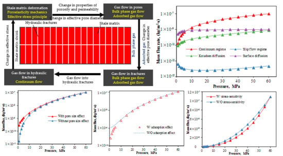
:Gas flow mechanisms in shale reservoirs with multiscale pores and fractures are extremely complex. In this study, a dual fracture framework model was adopted to describe gas flow in multiscale shale reservoirs. Gas flow through a shale reservoir occurs through both the shale matrix and hydraulic fractures. This study considered bulk phase and adsorbed gas flow in the shale matrix. Next, a series of partial theories were combined to derive a fully coupled model simulating gas flow in multiscale shale reservoirs: (1) fractal theory was adopted to obtain the pore distribution within shale reservoirs; (2) mechanical equilibrium equations were used to investigate the stress-sensitivity of permeability and porosity; and (3) a Langmuir adsorption model was applied to describe the effects of gas adsorption/desorption. The proposed model was validated using traditional models as well as field data on gas production from Marcellus Shale, and was subsequently applied to study variations of mass flux in various flow regimes with respect to reservoir pressure. We found that mass flux in the slip flow regime decreased at first and then increased with decreasing reservoir pressure, while in the continuum regime, Knudsen diffusion and surface diffusion the mass flux decreased with decreasing reservoir pressure. Stress-sensitivity has a significant impact on bulk phase gas flow, while adsorption/desorption influence both the bulk phase gas flow and adsorbed gas flow. At high pressures, the impact of stress-sensitivity on total gas mass flux is greater than that of adsorption/desorption, while the reverse was true for low pressures. The proposed model shows promising applications for analyzing various gas flow regimes in multiscale pores/fractures, and accurately evaluating in situ apparent permeability.
1. Introduction
With its wide distribution and high resource potential, shale gas has received increasing attention and plays a more important role around the world [1,2,3,4]. Shale reservoirs have very low porosity and matrix permeability as compared to conventional gas reservoirs [2,3]. Rapid technical advances, such as horizontal drilling and hydraulic fracturing technologies, guarantee continued shale gas production [4]. For most shale gas basins in South China and North America, the initial reservoir pressure (pore pressure) is between 2.76 and 68.95 MPa, and the Knudsen number ranges between 0.0002 and 6.00 [5]. Shale reservoirs have complex pore/fracture structures and include numerous nanopores, micropores, and microcracks, as well as larger-scale hydraulic fractures created after hydraulic fracturing [2]. Due to these factors, gas flow through a shale reservoir is very complex: (1) various flow regimes may occur in pores/fractures of different scales [3]; (2) the high content of organic matter or clay minerals and a large surface area for adsorbed gas occurrence that implies complex gas flow mechanisms in shale reservoirs. When reservoir pressure decreases, the desorption of adsorbed gas occurs and the concentration gradient on the pore walls decreases, which results in surface diffusion of adsorbed gas [6]; and (3) stress-sensitivity and adsorption/desorption have effects on the apparent physical properties of shale reservoirs, thereby affecting the gas flow mechanism [7,8,9]. During the gas production process, the stress-sensitivity response to a decrease in reservoir pressure will induce matrix shrinkage, while desorption of adsorbed gas causes the effective pore diameter to increase [7]. In general, gas flow through a shale reservoir is controlled by the coupled effects of multiscale pores/fractures, dynamic changes in reservoir pressure, adsorption/desorption, and stress-sensitivity. The gas flow mechanism plays an essential role in both shale gas accumulation and production. Hydraulic fractures are the critical paths for gas transport into production wells, while shale matrix is the mainly reservoir space for shale gas accumulation. When gas is produced from the reservoir, the free gas in the hydraulic fractures will flow out firstly. Then the gas in the matrix will transfer into these fractures, which supply the natural gas production. Therefore, the matrix also plays a critical role in the gas depletion over the whole lifetime of the reservoir. Different from conventional reservoirs, the apparent permeability of shale reservoirs is dependent on pore sizes, and is greater than the intrinsic permeability, because other flow regimes including slip flow, transition flow, and free molecular flow may occur. Therefore, it is important to study the gas flow mechanism in shale matrixes and fractures.
Recently, studies of gas flow within shale reservoirs have mainly focused on gas flow in nano-scale pores by experimental analysis and numerical simulation [7,8,9,10,11,12]. However, most of those models ignored the coupled effects of dynamic behaviors and shale reservoir properties, such as multiscale pores/fractures, adsorption/desorption, and stress-sensitivity on both the bulk phase gas flow and adsorbed gas flow. In addition to that, the validity of such correlation models using empirical coefficients has been questionable [13,14,15,16,17,18]. Chen et al. [19] and Wu et al. [5] proposed gas transport models for describing gas flow in different scale fractures while considering the effects of the fracture shape; Mi et al. [20] established an apparent permeability model for describing gas flow in multiscale shale reservoirs without considering the effects of adsorption/desorption and stress-sensitivity; Wu et al. [3] proposed an apparent permeability model for evaluating gas flow in nano-scale shale matrix by coupling the effects of adsorption/desorption and stress-sensitivity; Sun et al. [4] revealed gas flow mechanisms in a shale matrix combined with the effects of surface diffusion and the thickness of the adsorbed gas layer; Zhang et al. [21] found that shale reservoirs are highly stress-dependent, which significantly affects gas transport mechanisms; and Moghaddam et al. [22] investigated the gas flow mechanisms in multiscale fractures in tight reservoirs while considering the coupled effects of adsorption/desorption and stress-sensitivity. Few previous studies have attempted to model all gas flow regimes in multiscale shale reservoirs while considering multiple effects as reservoir pressure changes [6]. For this reason, more research is needed to bridge this knowledge gap.
From the stated above, it is obvious that gas flow in shale reservoirs is influenced by many factors. There is an insight into the coupled effects of multiscale pores, adsorption/desorption, and stress-sensitivity on gas flow in shale reservoirs need to be carried out. In this study, a dual fracture model will be adopted for describing gas flow in shale reservoirs. Gas flow in shale reservoirs will be divided into two sections: gas flow in shale matrix and fractures, respectively. The fractal theory will be used to obtain the pore size distribution of shale matrix, and the effect of multiscale pores on gas flow mechanism. Langmuir adsorption model will be applied for describing the surface diffusion in the shale matrix, and evaluating the influence of the adsorbed layer on effective pore diameter. Then the effect of adsorption/desorption on gas flow mechanism would be obtained. The effect of stress-sensitivity on gas flow in shale reservoirs will be also considered. Further, individual gas flow models for various gas flow regimes in shale matrix and fracture will be proposed, respectively. Finally, a comprehensive gas flow model for describing gas flow in shale reservoirs with the coupled effects of multiscale pores, adsorption/desorption, and stress-sensitivity under a dynamic change in reservoir condition will be obtained by combining with those individual gas flows models.
2. Mathematical Model
Traditionally, single-porosity models [7,10], dual-porosity models [22,23], and triple-porosity models (dual fracture models) [24,25] are used to describe gas flow in shale reservoirs. However, single-porosity and dual-porosity models assume that the pore and fracture properties are uniform across the porous medium, while actual shale reservoirs include multiscale pores and fractures with different properties. In this case, a dual fracture model is used to capture the heterogeneity of the reservoir by dividing the porous mediums into classes and assigning each one different property [6]. As described above, the scale of the pores and fractures affect gas flow mechanisms in shale reservoirs. Fractured reservoirs have significant variation in the scale of pores and fractures. Therefore, it is reasonable to construct a dual fracture model for describing gas flow mechanisms in shale reservoirs based on the effects of multiscale pores and fractures on gas flow.
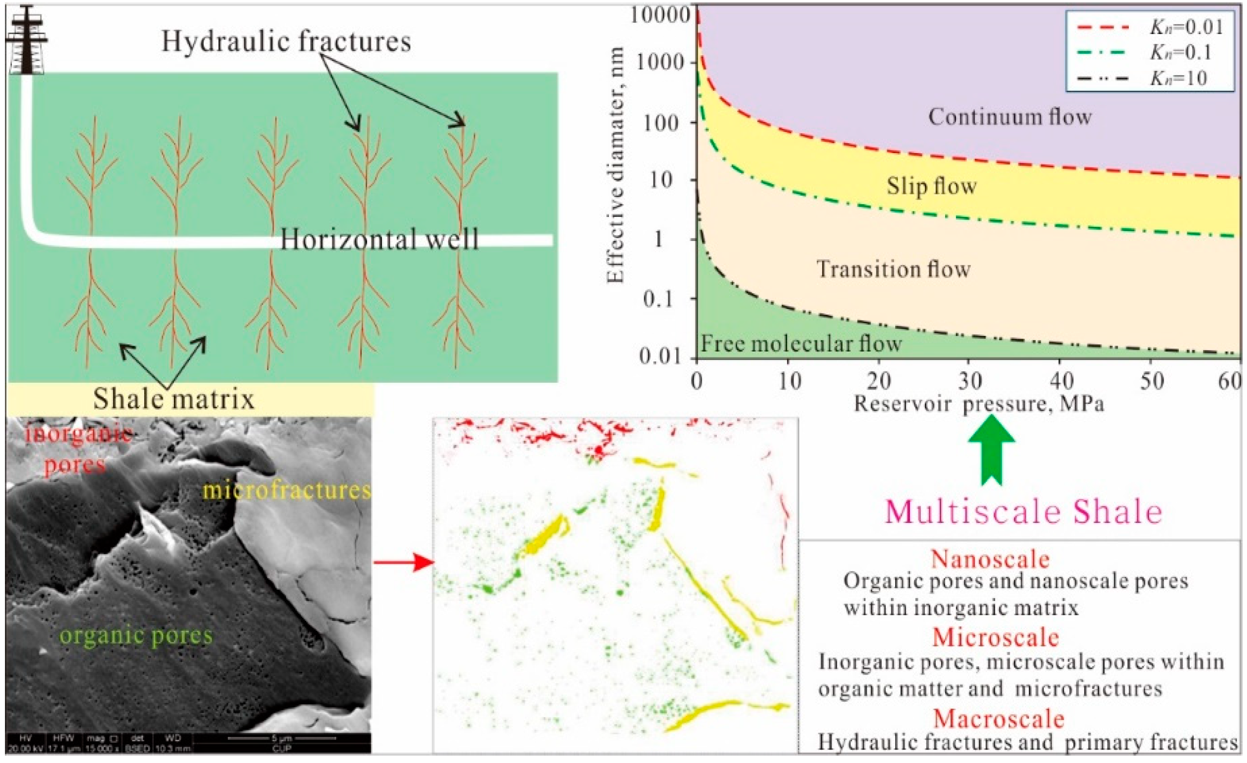
The effects of multiscale pores and fractures on gas flow can be summarized as follows: (1) gas flow mechanisms for different scale pores and fractures vary with respect to the reservoir pressure; and (2) gas flow regimes at fixed scale pores and fractures varied with changes in reservoir pressure. Gas flow regimes of bulk phase gas through porous media are classified into four types based on the Knudsen number Kn, namely, the continuum regime (Kn < 0.01), the slip flow regime (0.01 < Kn < 0.1), the transition regime (1 < Kn < 10), and the free molecular regime (Kn > 10). The Knudsen number is defined as follows [8,26]:
where de is the characteristic length of the flow geometry, considered to be the effective pore diameter, and λ is the mean free path of the gas molecules, given by [27]:
where T is the temperature, d0 is the diameter of a molecule of methane, kB is the Boltzmann constant, and p is the reservoir pressure.
Various bulk phase gas flow regimes may occur in shale reservoirs [7]. When gas is produced from a shale reservoir, the bulk phase gas in the hydraulic fractures with large scales will flow out firstly. Then the bulk phase gas in the pores and fractures in the matrix with small scales will transfer into hydraulic fractures. The adsorption/desorption process of adsorbed phase gas occurs with changes in gradient concentration along the pore walls with nanoscales, resulting in surface diffusion. Bulk phase gas and adsorbed gas in the pores and fractures of matrix supply the shale gas production. When the gas is produced from the reservoir, the gas pressure will decrease to a lower magnitude, and effective stress will be changed. This variation of effective stress will affect the average pores radius of the matrix, which means that the intrinsic permeability is a variable parameter [6]. When reservoir pressure decreases, the gas flow regimes of bulk phase gas in different scale pores and fractures are transformed from the continuum regime to the slip flow regime, and finally to the transition regime. The free molecular regime only occurs in nanopores at low pressures (Figure 1). Under geological conditions, the transition and free molecular regimes are mainly observed in nanoscale pores, the slip flow regime is mainly observed in microscale pores, and the continuum regime is mainly observed in microscale pores/fractures and macroscale fractures. Based on the dual fracture model [25], a shale reservoir was divided into two sections, namely, hydraulic fractures and matrices (between hydraulic fractures) with well-developed nano–micro-scale pores and micro-macroscale natural fractures. Both bulk phase gas flow and adsorbed gas flow occur within the shale matrix. However, only bulk phase gas flow occurs within hydraulic fractures. Fracture properties play an important role in reservoir performance in the early life of a shale gas well. However, it is the properties of the matrices that control the gas flow behavior over longer periods of time [17].
This study takes the Marcellus Shale as an example. The study area (Marcellus) is located in the eastern United Three major orogenic events affected the sedimentation and structure in the basin during the Paleozoic Era. From oldest to youngest these are the Taconic orogeny (Ordovician), the Acadian orogeny (Devonian to Early Mississippian), and the Alleghanian orogeny (Mississippian to Permian) [28]. The Marcellus Shale, which is Devonian age (416–359.2 Ma), was deposited during a period of rapid transgression in anoxic to euxinic waters within a restricted foreland basin. The Marcellus Shale is characterized by its organic-rich nature and black color, and is integrated with the lower Onondaga Limestone and the upper Tully Limestone [29]. The vitrinite reflectance (Ro) values between 2% and 2.2%, indicating that the maturity of shale is mainly in over-mature stages [30], and are dominantly in the thermogenic generation stage.
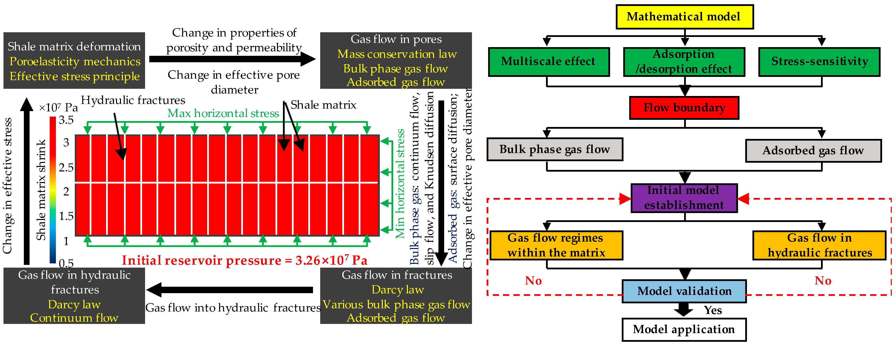
The calculation procedures include five stages, which are shown in Figure 2. First, a suitable mathematical model will be applied for describing gas flow in multiscale shale reservoirs. Second, flow boundaries (pore scales) of various flow regimes will be obtained for a given condition with considering coupled effects of multiscale pores/fractures, adsorption/desorption, and stress-sensitivity. Third, individual flow models for various flow regimes will be proposed. Fourth, those individual flow models will be verified by comparing them with traditional models and matching the production data. Further, the coupled model obtained by combining those individual flow models would be applied for modeling gas flow in the research area.
The reservoir characteristic parameters and the field production data of a shale gas well, which was located between the lower section and upper section of the Marcellus formation, were chosen to verify the proposed models and conduct the further analysis. The initial reservoir conditions of the Marcellus Shale well were characterized by a deeper vertical depth of 2619.1 m, a high reservoir temperature of 352.55 K, an overpressure condition with a high initial reservoir pressure of 3.26 × 10⁷ P, and a high gas saturation of 0.70, but low initial matrix permeability (0.0006 mD) and porosity (6.5%) [28]. In addition, the two main adsorption parameters (Langmuir pressure and Langmuir volume) of Marcellus Shale were an average of 2.5 m3/t and 3.0 × 10⁷ Pa, which illustrates that the Marcellus Shale had good adsorption capability [6].
In order to successfully achieve the aims of this study, the reservoir parameters above were basic parameters for the simulation of gas flow in multiscale shale reservoirs. In addition, other parameters such as gas viscosity, fracture permeability, surface diffusion coefficient, drainage area, and horizontal well length need to be obtained. Fortunately, a lot of research has been conducted on gas flow in the Marcellus Shale, and appropriate reservoir parameters have been given by previous studies [6,28,31].
The initial reservoir pressure of shale gas development sections is dominated by <60 MPa. The pore scale boundaries of various flow regimes vary with the change in reservoir pressure, and are more sensitive response to the low reservoir pressure (<5 MPa) (Figure 1). Considering the initial geological conditions and the response of gas flow boundary to reservoir pressure, the initial reservoir pressure is set to 60 MPa, and the reservoir pressure is discretized as follows: the simulated pressure steps of reservoirs pressure between 5 and 60 MPa, and <5MPa, are 5 MPa and 1 MPa, respectively. Then the boundaries of various flow regimes for a certain reservoir pressure would be obtained. Furthermore, the corresponding parameters will be replaced in the proposed flow models, and then a gas flow varying with the dynamic changes in reservoir conditions would be obtained.
3. Formulation of the Mathematical Model
3.1. Pore Size Distribution within Matrix
Pores in tight gas reservoirs have fractal characteristics that range from a micrometer scale to a nanometer scale [9]. Understanding the pore size distribution is critical to modeling gas flow in shale reservoirs. Previous studies have found that the pore size distribution of a porous media can be mathematically obtained using fractal theory [32]. The number of pores of a radius that is greater than a certain value r is given by:
where rmax is maximum pore radius in a shale reservoir. Df is the pore area fractal dimension, 1 < Df < 2, and is given by [9]:
where φ is the effective porosity of a shale reservoir, rmin is minimum pore radius of a shale reservoir, ξ = 2 in two dimensions, and ξ = 3 in three dimensions.
From Equation (3), we can see that there is a relationship between pore number and pore radius. Furthermore, the total number of pores within a shale reservoir can be obtained by [33]:
By differentiating Equation (3), the number of pores with a pore radius between r and r + dr can be defined as follows:
Furthermore, the frequency of pores with a pore radius between r and r + dr is found by combining Equations (5) and (6):
where stands for the probability density function, which satisfies the following condition:
Based on probability theory, the probability density function f(r) also satisfies the relationship as follows:
Clearly, the prerequisite for the availability of Equation (9) is that:
In general, Equation (10) is valid if rmin/rmax ≤ 10−2 [28]. For shale reservoirs, the maximum pore radius is far greater than the minimum pore radius. Thus, fractal theory is a valid method for defining the pore size distribution of shale reservoirs.
3.2. Modified Effective Pore Diameter with Effects of Adsorption/Desorption and Stress-Sensitivity
Both adsorption/desorption and stress-sensitivity induced by dynamic reservoir pressure changes have impacts on the effective pore diameters of shale reservoirs. To accurately evaluate gas flow within a shale matrix, it is important to obtain the effective pore diameter size for shale reservoirs under different reservoir pressure conditions while considering the effects of adsorption/desorption and stress-sensitivity.
3.2.1. Stress-Sensitivity
The effects of stress-sensitivity on gas flow within shale reservoirs incorporate two aspects: (1) matrix and fracture permeability, as well as porosity, which decreases with decreasing reservoir pressure (increasing effective stress); and (2) matrix shrinkage with increasing effective stress decreases the effective pore diameter.
Yu and Sepehrnoori [34] studied the variation of fracture conductivity with respect to changes in reservoir pressure. The fracture conductivity is defined as the product of fracture width and fracture permeability, as given by:
where Fc is the fracture conductivity, wf is the fracture width, and kf is the fracture permeability.
Based on the experimental data, the relationship between the fracture conductivity multiplier (a ratio of fracture conductivity at different pressures divided by fracture conductivity at the initial pressure) and pressure was obtained through software modeling using CMG [35]. The results indicated that the fracture conductivity multiplier exponentially decreased with decreasing pressure (Figure 3). In addition, other scholars have described the relationship between fracture permeability and reservoir pressure [31], as follows:
where kfi is the fracture permeability for a given reservoir pressure, kf0 is the initial fracture permeability, cf is the compressibility for the fractures, and p0 and pi are initial reservoir pressure and a given reservoir pressure, respectively.
The results from numerical simulation and experimental data showed that both matrix permeability and matrix porosity decreased exponentially with an increase in effective stress. Furthermore, the relationships between matrix porosity, matrix permeability, and reservoir pressure were obtained by [21,36]:
where φ0 is the initial matrix porosity, k0 is the initial matrix permeability, φi and ki are the matrix porosity and matrix permeability with respect to a given reservoir pressure pi, and cp and ck refer to compressibility for porosity and compressibility for permeability, respectively.
Furthermore, the pore diameter is calculated by [6]:
Based on Equations (13) and (15), the change in effective pore diameter is defined as:
3.2.2. Adsorption/Desorption
In the process of shale gas production, desorption of adsorbed gas caused by decreasing reservoir pressure leads to surface diffusion. Gas adsorption characteristics of shale reservoirs can be described by adopting the Langmuir isotherm model [37]:
where Vi is the adsorbed gas content correspond to a given reservoir pressure pi, VL is the Langmuir volume, and PL is the Langmuir pressure.
The Langmuir isotherm model assumes that the adsorbed gas on the pore surfaces is monolayer adsorption. Thus, the coverage of adsorbed gas on the pore surfaces is defined as [3]:
As stated above, the change in effective pore diameter caused by the adsorption/desorption is expressed as:
3.2.3. Modified Effective Pore Diameter
Assuming a pore within a shale reservoir with an initial pore diameter d, Δda and Δds are the changes in diameter caused by the effects of adsorption/desorption and stress-sensitivity, respectively. Furthermore, the modified effective pore diameter considering the effects of adsorption/desorption and stress-sensitivity is given by:
3.3. Gas Flow Regimes within the Matrix
3.3.1. Bulk Phase Gas Flow Regimes
1. Continuum regime
The application of Darcy’s law to viscous gas flow in the continuum regime (Kn < 0.01) is more recognized [38,39]. Mass flux in the continuum regime is given by [31]:
where Mc is the mass flux in the continuum regime, M is the molar mass of the gas, Z is the compressibility factor, k is the matrix permeability, μ is dynamic viscosity of the fluid, and Δp is the gradient in reservoir pressure.
2. Slip flow regime
A porous medium can be considered to be a bundle of capillaries with varying cross-sectional areas. The total mass flux in the slip flow regime is the sum of the mass flux from all the individual capillaries [9]. The mass flux in the slip flow regime through a single capillary is given by a Hagen–Poiseulle-type equation [8], as follows:
where ms(r) is the mass flux in the slip flow regime through a single capillary, and τ is the tortuosity factor of porous media.
By combining Equations (6) and (21), the total mass flux in the slip flow regime through a shale matrix with different scale pores can be expressed as:
where Ms(r) is the total mass flux in the slip flow regime through the shale matrix, and rKn = 0.01 and rKn = 0.1 are the corresponding pore radii with respect to Kn = 0.01 and Kn = 0.1 for a given inlet pressure, respectively.
3. Free molecular and transition regimes (Knudsen diffusion)
Although some modified conventional models may be applied to the free molecular and transition regimes (i.e., Darcy’s law with Knudsen correction and a Hagen–Poiseuille-type equation), the validity of such models with empirical coefficients is questionable. The Knudsen diffusion equation is better equipped to describe the free molecular and transition regimes [8], especially for gas flow with higher Knudsen numbers (close to 10) [39]. So the free molecular and transition regimes in a matrix are collectively referred to as Knudsen diffusion. Furthermore, the Knudsen diffusion coefficient is given by [14]:
where Df is the Knudsen diffusion coefficient, and rf is the average effective pore radius of the pores in which free molecular and transition regimes occur. Based on Equations (7) and (9), the rf can be found by:
where rf-min and rf-max are the minimum and maximum average effective pore radii for pores in which free molecular and transition regimes occur.
Furthermore, the mass flux in Knudsen diffusion is given by:
3.3.2. Adsorbed Gas Flow
For the adsorbed gas, the adsorption/desorption process occurs with changes in reservoir pressure. In addition to that, surface diffusion also occurs because of the change in gradient concentration along the pore walls. The mass flux in surface diffusion is given by [3,6]:
where Ms is the mass flux in surface diffusion, Ds is the surface diffusion coefficient, ζm is the modified gas coefficient, and C is the adsorbed gas concentration on the pore walls.
Assuming that the adsorbed gas on the pore walls is monolayer adsorption, the gas concentration decreases with decreasing reservoir pressure. Furthermore, when considering the effect of adsorbed gas content, the adsorbed gas concentration can be expressed as [3]:
3.3.3. Comprehensive Gas Flow Model
Based on the above studies, both bulk phase gas flow and adsorbed gas flow occur in a shale matrix. The former includes the continuum regime, the slip flow regime, and Knudsen diffusion. Furthermore, the comprehensive gas flow model for describing gas flow through shale matrix while considering the coupled effects of adsorption/desorption and stress-sensitivity is obtained using:
3.4. Gas Flow in Hydraulic Fractures
Hydraulic fractures are on a far larger scale than the pores and fractures within the shale matrix. Only bulk phase gas is stored in hydraulic fractures. The mechanism for gas flow in hydraulic fractures is the single continuum regime. Darcy’s law is more reasonable for describing gas flow in hydraulic fractures [6]. Based on this, the mass flux in hydraulic fractures can be expressed as:
4. Model Validation
Because of the coexistence of bulk phase gas and adsorbed gas in shale reservoirs, different mechanisms of the effects of adsorption/desorption and stress-sensitivity, and the lack of a corresponding experimental instrument it is difficult to conduct gas transfer experiments while considering the effects of adsorption/desorption and stress-sensitivity on both bulk phase and adsorbed gas flow in the shale matrix and hydraulic fractures. Thus, gas flow models for the shale matrix and hydraulic fractures should be validated separately. Prior research has derived the rationalities for the surface diffusion model and the gas flow model for hydraulic fractures [3,6]. In this study, traditional models were used to validate the bulk phase gas flow model, so as to indirectly verify the reliability of the fully coupled model.
From the analysis above, several processes should be taken into account to simulate the gas flow in shale reservoirs. Due to the complex nature of these processes, the available commercial simulators cannot be used easily to accurately model the gas flow [22]. Fortunately, individual flow models for various flow regimes were proposed in this study. The whole set of those coupled models as presented in the previous section was implemented into and solved by the MATLAB software, which can use to solve those nonlinear differential models successfully.
4.1. Comparison with Traditional Models
4.1.1. Civan Model
Civan [27] described gas flow in tight porous media using the Beskok and Karniadakis model [8]. In Civan’s model, the apparent permeability of a shale reservoir is expressed as:
where b is the slip coefficient and b = −1 in the slip flow regime, and a(Kn) is the rarefaction coefficient and given by [8]:
4.1.2. Dusty-Gas Model (DGM Model)
The DGM model is a coupled multiple gas flow model consisting of mechanisms for viscous flow, Knudsen diffusion, and other diffusion [40]. In the DGM model, the apparent permeability of a shale reservoir is given by:
where bk is the Klinkenberg coefficient.
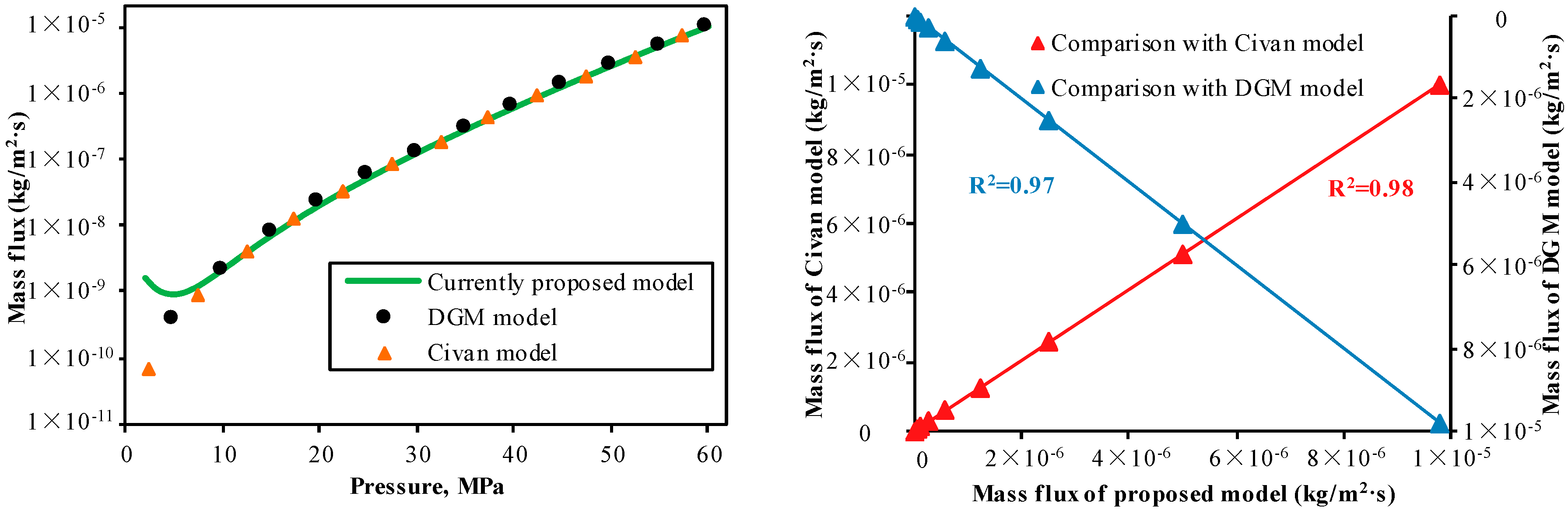
4.1.3. Comparison of the Models
As can be observed from Figure 4, there was good agreement between the mass flux calculated by the current and traditional models, with high positive correlations between the proposed model and Civan model (R2 = 0.98) as well as between the proposed model and the DGM model (R2 = 0.97). In addition, the error percentages between the mass flux calculated by the current and traditional models are small. The error percentages between the proposed model and the Civan model, as well as between the proposed model and the DGM model, range from 2.26% to 5.73% (avg. 3.75%) and 0.39% to 6.61% (avg. 1.83%), validating the suitability of the current model for evaluating bulk phase gas flow through shale reservoirs. However, at reservoir pressures of <10 MPa, the mass flux calculated by the proposed model was slightly higher than that of the traditional models. This is because the proposed model considered multiple effects, while the DGM model only considered viscous flow and Knudsen diffusion. The Civan model with empirical coefficients may have led to differences between the results. The mass flux curve obtained by the proposed model had a rebound trend at low pressures because the mass flux in free molecular regime within nanoscale pores was significant at low pressures, which increased the mass flux of the bulk phase gas.
4.2. History Matching for Marcellus Shale
In order to further verify the reliability of the fully coupled model, a history matching of field data from Marcellus Shale was applied. In general, flowing bottom hole pressure and gas production data from shale wells are used to perform history matching to validate reservoir models. The reservoir parameters and flowing bottom hole pressure curve for Marcellus Shale were obtained from the published literature [6,28,35], as show in Table 1. The parameters for the shale matrix and hydraulic fractures were obtained by matching the production data as listed in Table 1.
The results derived from the fully coupled model were highly correlated with the field data (Figure 5), with a high positive correlation (R2 = 0.88) and small error percentages (avg. 7.29%), indicating that the fully coupled model can be applied for the analysis of all the flow regimes in pores and fractures at differing scales. In addition, the initial gas production rate simulated by the fully coupled model was higher than the actual gas production rate, and the error percentage between them even can reach 35.6%. This is due to the fact that water flow back will reduce the initial gas production rate, but the gas will dominate the production over the later period of the depletion [6].
5. Results and Discussion
In this simulation study, we calculated the mass flux in various flow regimes to reveal the effects of each one on gas production. Gas flow mechanisms within hydraulic fractures are the same as those in shale matrix fractures. In this study, we assumed that gas flow in hydraulic fractures was equivalent to the continuum regime in a shale matrix, and that compressibility for matrix permeability and hydraulic fracture permeability had the same value. The mass flux in the continuum regime, the slip flow regime, Knudsen diffusion, and surface diffusion were obtained using Equations (21), (22), (26) and (27), respectively. The simulation parameters are listed in Table 2.
5.1. Comparison of Mass Flux in Various Flow Regimes
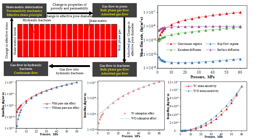
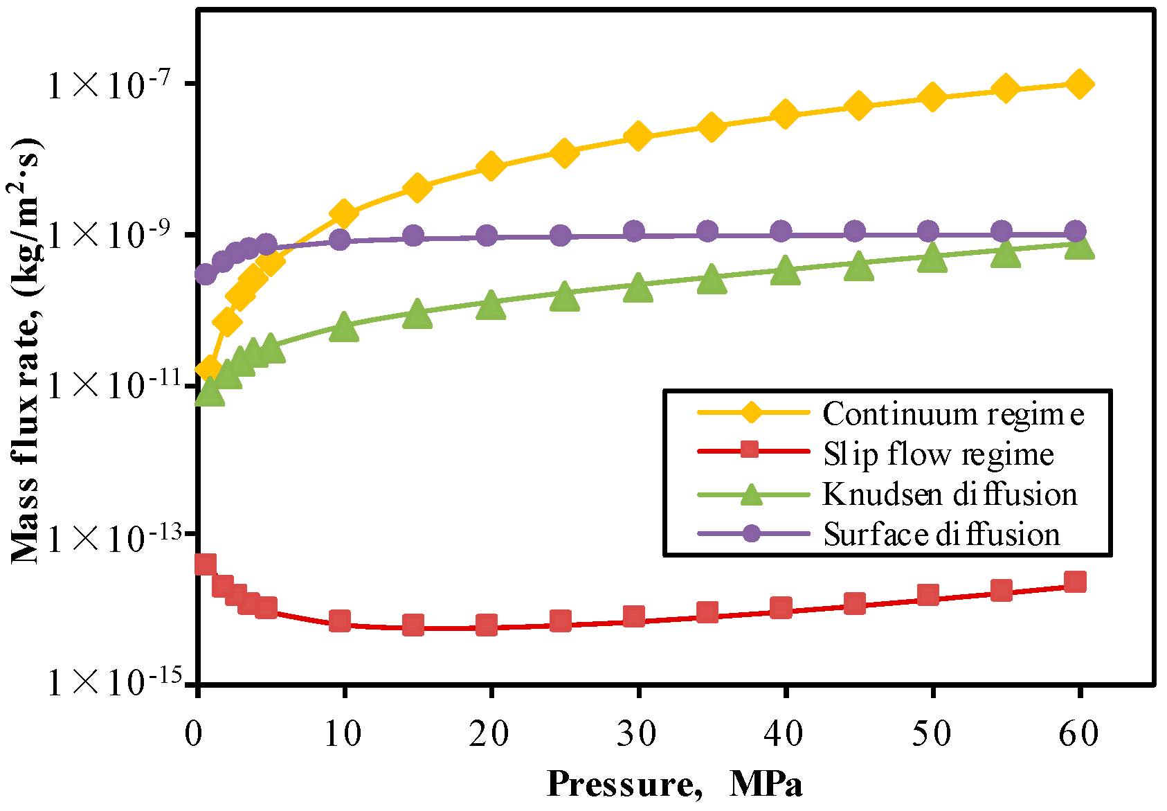
The relationships between mass flux under various flow regimes and reservoir pressures are shown in Figure 6. For the slip flow regime, mass flux decreased and then increased with decreasing reservoir pressure, with a minimum mass flux occurring at a reservoir pressure of 10 MPa. This was due to the fact that the effective pore diameter size decreased when stress-sensitivity reduces mass flux in the slip flow regime (a “negative effect”). Conversely, effective pore diameter size increased when the desorption of adsorbed gas enhanced mass flux in the slip flow regime (a “positive effect”). At reservoir pressures of <10 MPa, the negative effect had a greater impact on the slip flow regime than the positive effect, while the reverse was the case at reservoir pressures of >10 MPa. Mass fluxes in the continuum regime, Knudsen diffusion and surface diffusion decreased with decreasing reservoir pressure. For the continuum regime, the effective stress increased with decreasing reservoir pressure, leading to changes in both matrix and hydraulic fracture permeability, which in turn lead to a reduction in mass flux. For surface diffusion, the concentration gradient on the pore walls decreased with decreasing reservoir pressure, resulting in a weakening of the driving force of surface diffusion [3].
5.2. Impact of Multiscale Pores
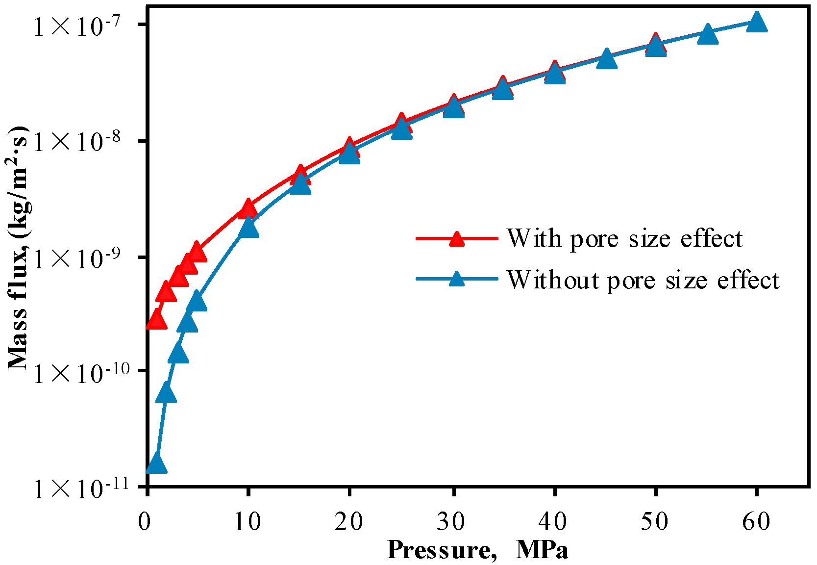
Different from conventional reservoirs, the pores in the shale matrix are mainly nanoscales and microscales. If the effects of multiscale pore structure on gas flow capacity had not been considered, the mass flux for shale reservoirs will have been underestimated, especially under low reservoir pressure (<10 MPa) (Figure 7). This is due to the multiscale pores developed in shale reservoir. With the decrease of reservoir pressure, the proportion of the pores in the slip flow and Knudsen diffusion increase, resulting in an increase of the total mass flux. The apparent permeability is higher than the intrinsic permeability.
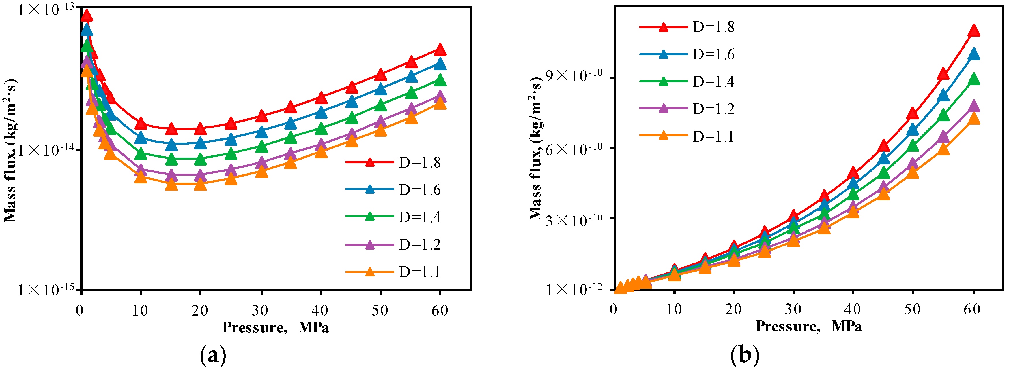
The gas flow models for various flow regimes show that both slip flow and Knudsen diffusion are functions of pore size distribution, which means that pore size distribution has a significant influence on them. Pore size scales of various flow regimes are fixed for a giving reservoir pressure, and pore size distribution is determined by the pore fractal dimension. The mass flux in the slip flow and Knudsen diffusion was decreasing with the decreases in pore fractal dimensions (Figure 8). Because the frequency of pores with a certain pore size scale is exponential positive correlation with pore fractal dimension (Equations (3)–(7)), which means that the larger the fractal dimension, the greater the number of pores in the slip flow and Knudson diffusion, and the larger the corresponding mass flux.
5.3. Impact of Adsorption/Desorption
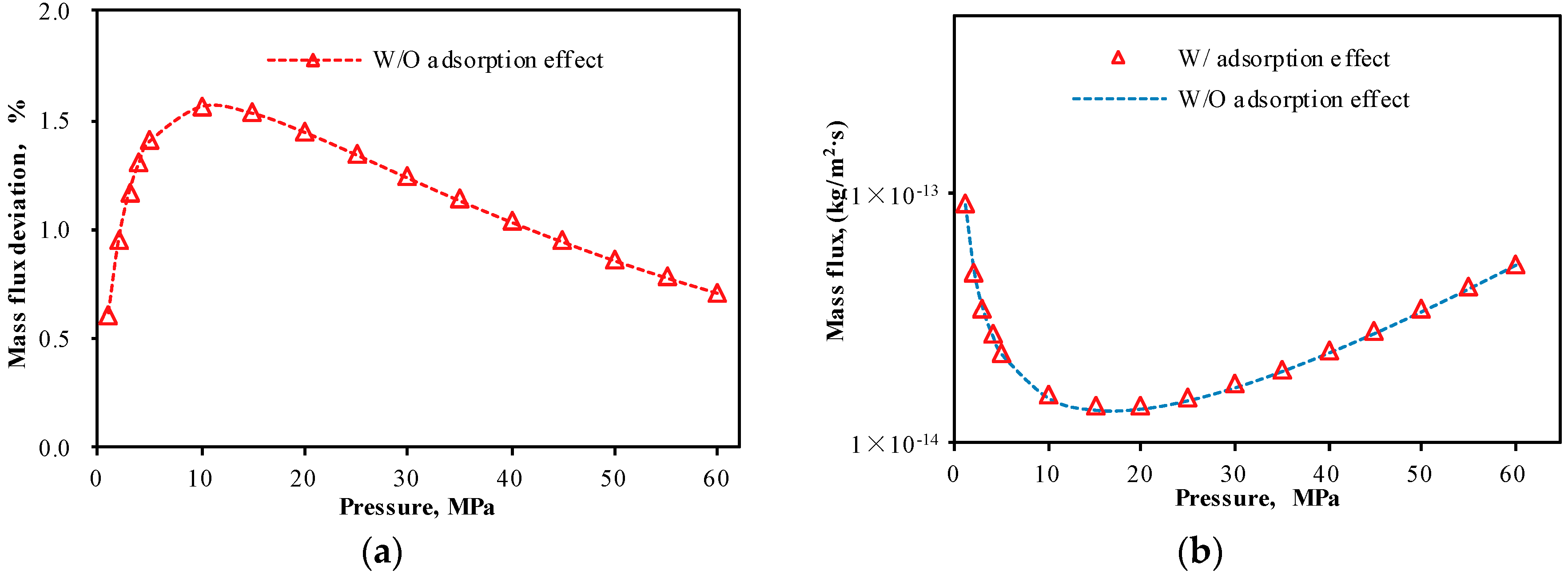
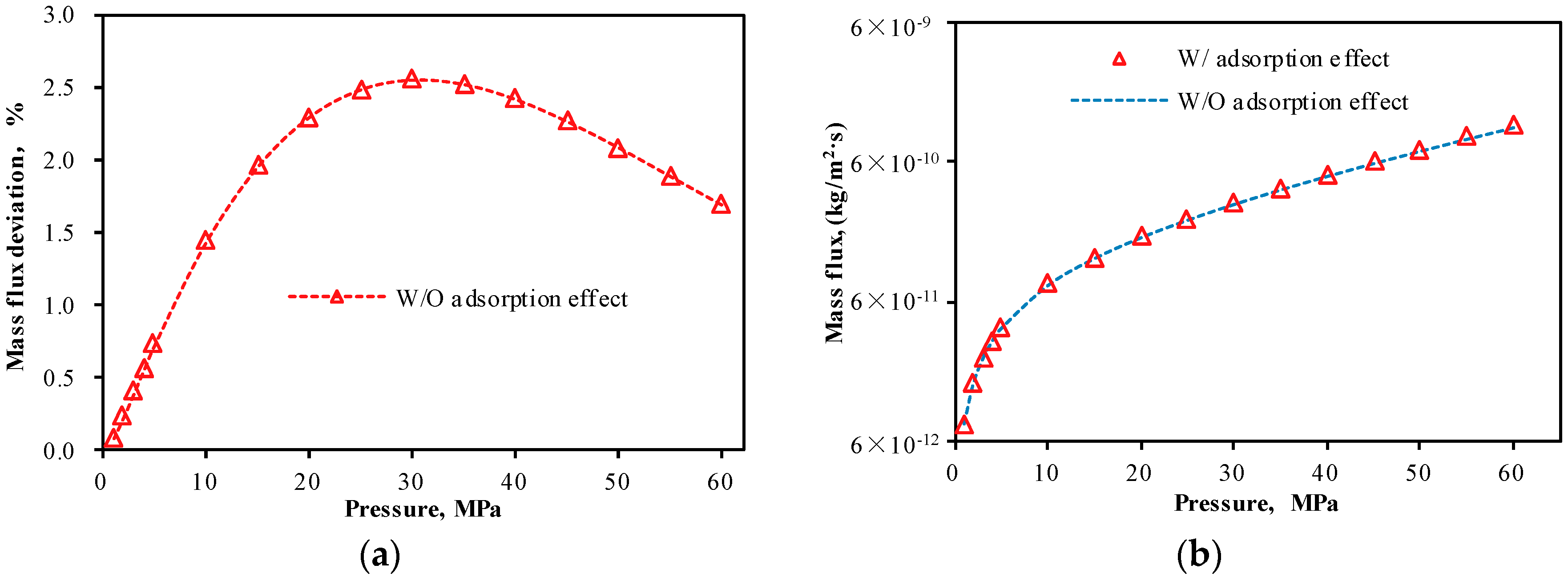
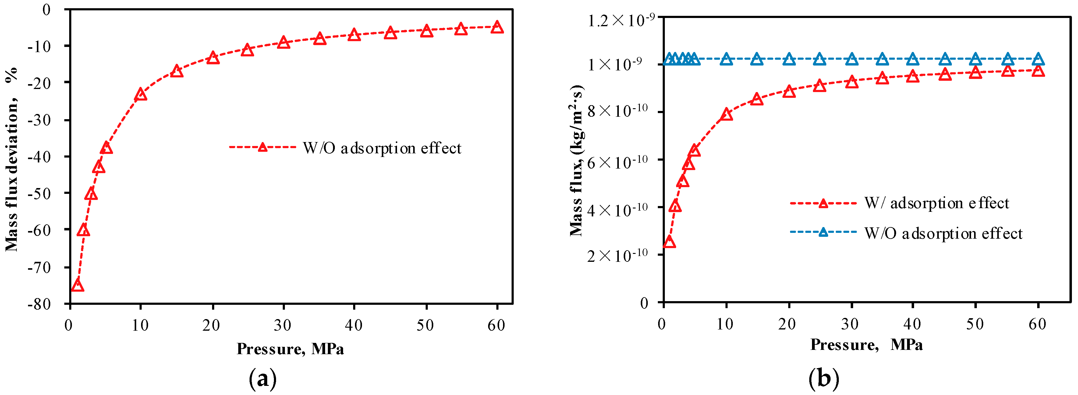
When gas was extracted from the reservoir, the adsorbed gas content and the adsorption layer thickness decreased, which led to increases in effective porosity and effective pore diameter for bulk phase gas flow. Conversely, the existence of adsorbed gas occupied the available space for gas flow. The higher the adsorbed gas content, the smaller the effective pore diameter for bulk phase gas flow. The mass flux in the slip flow regime and Knudsen diffusion will have been underestimated if we had not considered the impact of adsorption/desorption (Figure 9a and Figure 10a). Mass flux deviations (a ratio of the difference between actual mass flux and mass flux without considering the impact of adsorption/desorption to the mass flux without considering the impact of adsorption/desorption) in the slip flow regime and Knudsen diffusion induced by adsorption/desorption decreased and then increased with decreasing reservoir pressure, with maximum deviations of 1.56% and 2.54%, respectively (Figure 9a and Figure 10a). Conversely, mass flux under surface diffusion would have been overestimated without considering the impact of adsorption/desorption (Figure 11b). Mass flux deviation under surface diffusion increased with decreasing reservoir pressures and was particularly significant at low pressures, with a maximum deviation of −75% (Figure 11a). Adsorption/desorption had impacts on both bulk phase gas and adsorbed gas flow. The total mass flux would have been underestimated without considering the impact of adsorption/desorption (Figure 12b). The total mass flux deviation increased with decreasing reservoir pressure (Figure 12a) because there was a higher proportion of surface diffusion at low pressures.
5.4. Impact of Stress-Sensitivity
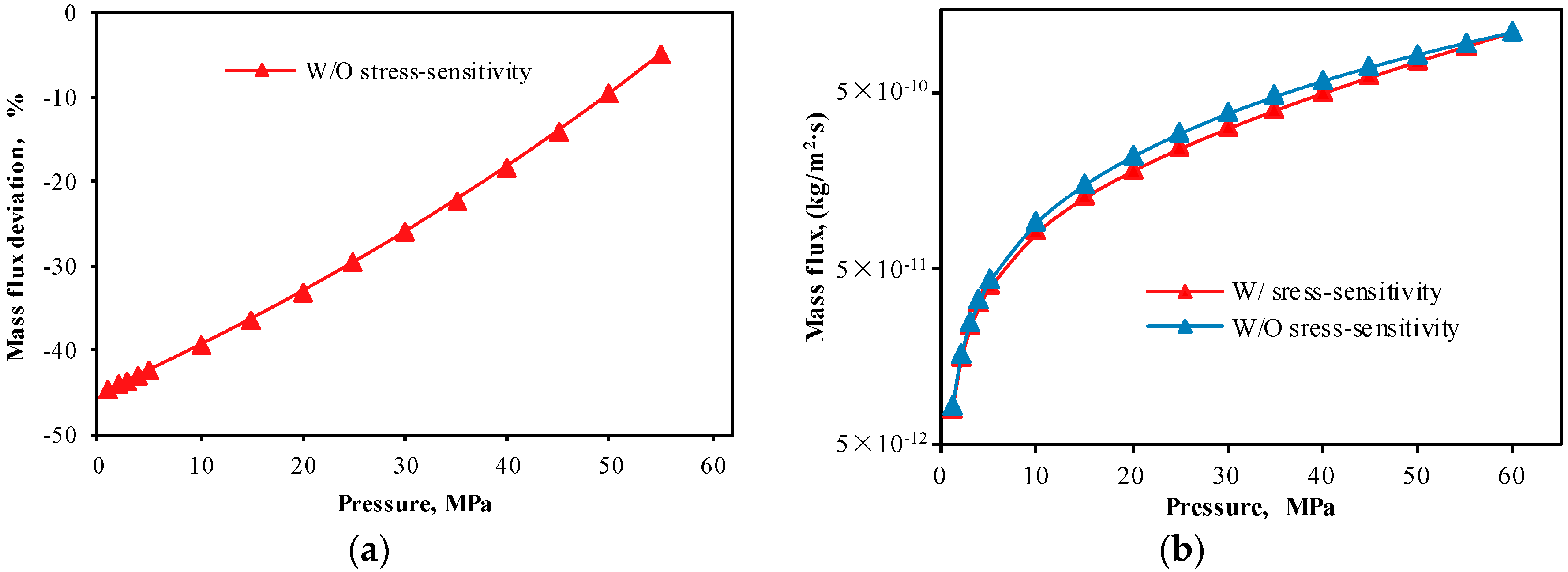
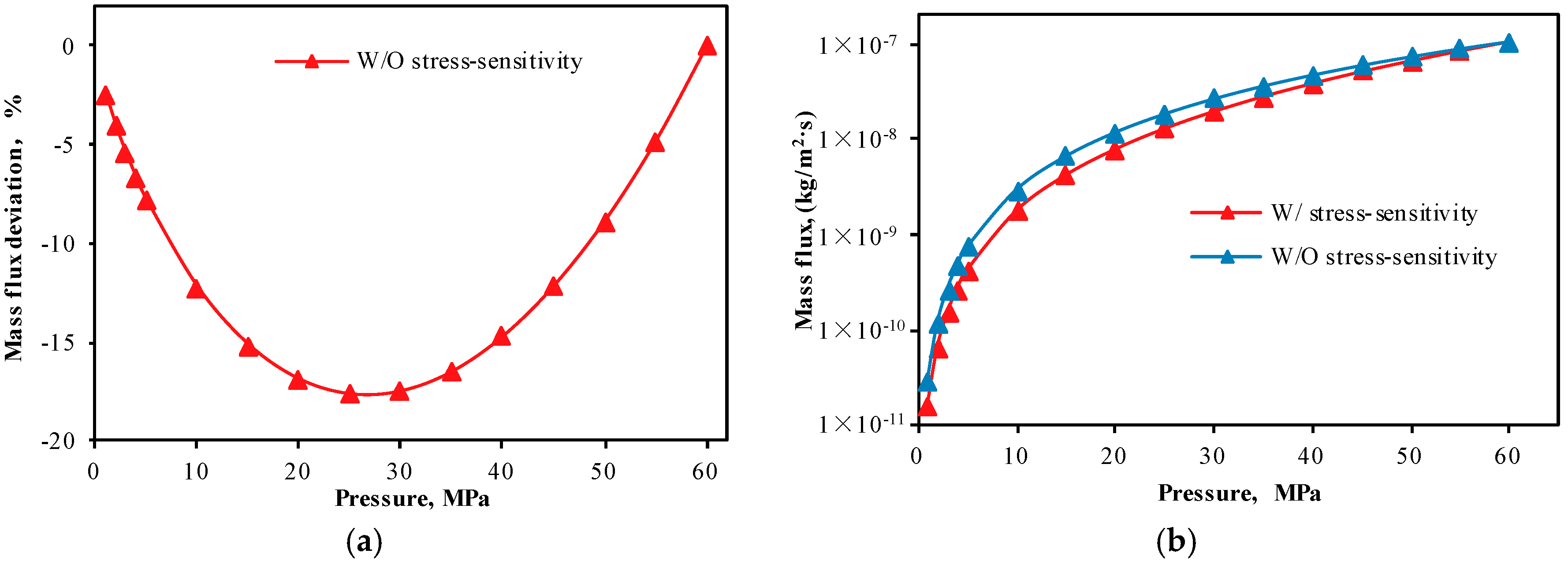
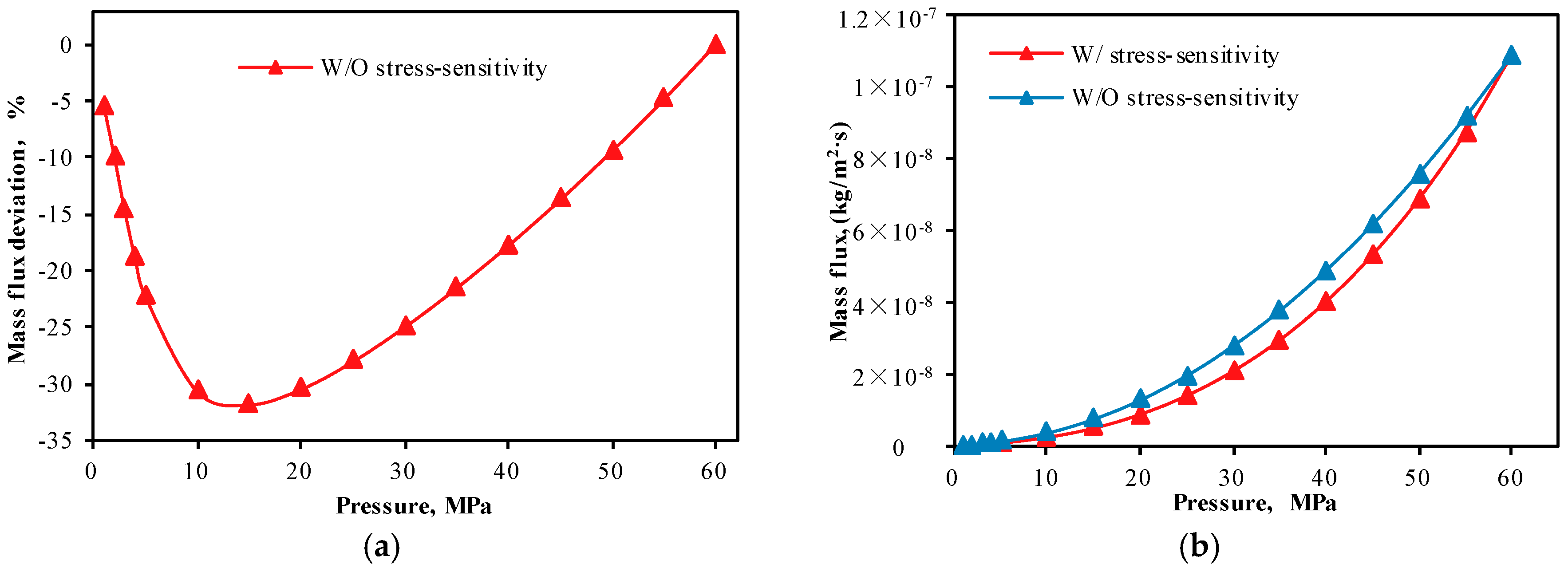
The mechanical compression of a shale matrix after gas extraction led to losses in porosity, permeability, and effective pore diameter. Mass flux in the continuum regime, the slip flow regime, Knudsen diffusion, and the total mass flux would have been overestimated without considering the impact of stress-sensitivity (Figure 13b, Figure 14b, Figure 15b and Figure 16b), with maximum deviations of −44.57%, −97.09%, −17.65%, and −31.78%, respectively (Figure 13a, Figure 14a, Figure 15a and Figure 16a). For the continuum and slip flow regimes, the mass flux deviations caused by stress-sensitivity increased with decreasing reservoir pressure. In addition, the mass flux deviations in Knudsen diffusion and total mass flux caused by stress-sensitivity decreased and then increased with decreasing reservoir pressure, with maximum deviations occurring at reservoir pressures of 25 MPa and 15 MPa, respectively (Figure 15a and Figure 16a).
5.5. Comparison of Impacts of Adsorption/Desorption and Stress-Sensitivity
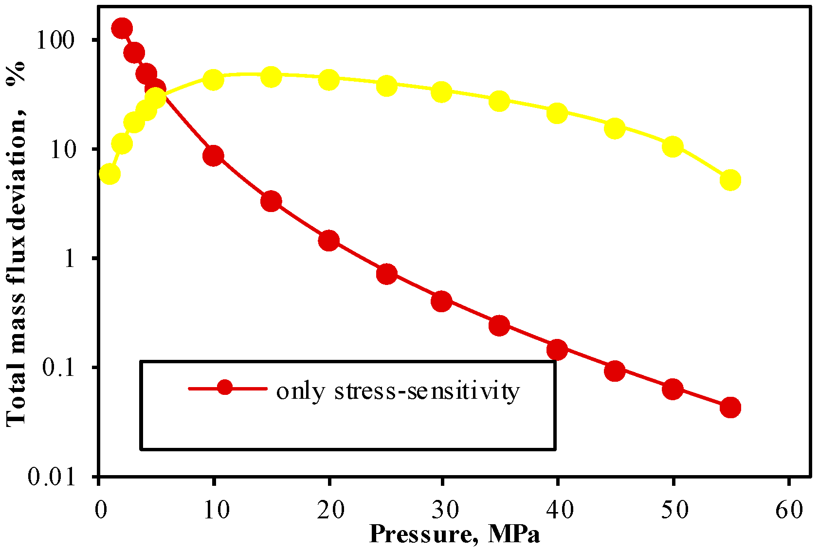
As the results above have shown, stress-sensitivity mainly affects bulk phase gas flow, while adsorption/desorption affects both bulk phase gas flow and adsorbed gas flow. For bulk phase gas, the impact of stress-sensitivity was far greater than that of adsorption/desorption, while the reverse was the case for adsorbed gas. The total mass flux would have been overestimated without considering the impact of adsorption/desorption, with a maximum deviation of 46.59% (Figure 17). The impacts of adsorption/desorption on gas flow in shale reservoirs included two aspects: (1) shrinkage/swelling of the effective pore diameter as a result of gas desorption/adsorption impacted bulk gas flow; and (2) surface diffusion that occurred with gas desorption increased the transport capacity of adsorbed gas, especially at low pressures. At reservoir pressures of >5MPa, the impact of stress-sensitivity on total mass flux was far greater than that of adsorption/desorption, while the reverse was the case at reservoir pressures of <5MPa because adsorption/desorption had a significant influence on surface diffusion, which dominated the total mass flux at low pressures.
6. Conclusions
In this study, a fully coupled model for describing gas flow in multiscale shale reservoirs by combining the effects of pore size distribution, stress-sensitivity, and adsorption/desorption was proposed. The results of this study are available for quantitatively evaluating the gas flow capacities. There are two main advantages in comparison with other gas flow model for evaluation of shale reservoirs. First, this coupled model includes several individual models that can be used to describe the corresponding flow regimes accurately, and the boundaries of various flow regimes can be obtained for a giving geological condition. Secondly, gas flow capacity of shale reservoirs is dynamic variables because of the coupled effect stated above. Based on the findings of the study, the following conclusions can be drawn:
- Pore size distribution has a significant influence on gas flow in shale reservoirs. Multiscale pore structure means that various bulk flow regimes may occur rather than single continuum flow dominant in shale reservoirs. The gas flow capacity will be underestimated without considering the impact of pore size distribution. Because the frequency of pores in a certain pore size scale is a positive correlation with fractal dimension. A large amount of pores in slip flow and Knudson diffusion with respect to a larger fractal dimension enhance the apparent permeability of shale reservoirs.
- The gas flow capacity will be overestimated without consideration of the effect of stress-sensitivity. Matrix permeability and fracture permeability decrease with decreasing reservoir pressure because of the extrusion resulted from an increase in effective stress. The variation on gas flow within fractures permeability caused by a change of effective stress is more significant than that on gas flow within the matrix with a high compressibility. In addition, Stress-sensitivity has a significant influence on bulk phase gas flow. Because matrix shrinkage with increasing effective stress, resulting in diminution of the effective pore diameter for bulk phase gas flow.
- Gas flow capacity of bulk phase gas will be overestimated without consideration of the impacts of adsorption/desorption due to the adsorbed gas molecules along the pore walls will reduce the available pore space for bulk phase gas flow. In addition, considerable adsorbed gas contents are stored in the small pores results in surface diffusion, which enhances the transport of gas molecules along molecular concentration gradients.
In addition, this coupled model also has some disadvantages: (1) Langmuir adsorption model was applied to describe the effects of gas adsorption, which means that adsorbed gas in shale reservoirs is a monolayer adsorption. Some previously research indicated adsorbed gas in micropores (<2 nm) within shale reservoirs at high pressures does not hold Langmuir isotherm (multilayer adsorption), resulting in more complexity of the change in effective pore diameter; (2) in this study, the adsorption parameters of Langmuir pressure and Langmuir volume were constants. However, the effects of adsorption capacity with different Langmuir pressure and Langmuir volume on gas flow in shale reservoirs were not discussed. In a further step, the effects of adsorption parameters such as Langmuir pressure, Langmuir volume, and adsorbed gas layer thickness that influence effective pore diameter and adsorbed gas concentration, and surface diffusion coefficient need to be evaluated to provide a more realistic view of the gas flow in shale reservoirs.
Author Contributions
Data curation, X.H.; Funding acquisition, Y.M.; Investigation, X.H.; Methodology, Y.L.; Software, Y.W. and X.H.; Writing—manuscript, X.H.; Writing—review and editing, X.H. and Y.Z.
Funding
This research was funded by the National Natural Science Foundation of China (No. 41402124) and the National Science and Technology Major Project (No. 2017ZX05035004-002).
Acknowledgments
This work was jointly sponsored by the National Natural Science Foundation of China (No. 41402124) and the National Science and Technology Major Project (No. 2017ZX05035004-002). The authors also sincerely appreciate the editors and the reviewers for helping to improve the manuscript.
Conflicts of Interest
The authors declare no conflict of interest.
References
- Wang, J.; Liu, H.Q.; Wang, L.; Zhang, H.L.; Luo, H.S.; Gao, Y. Apparent permeability for gas transport in nanopores of organic shale reservoirs including multiple effects. Int. J. Coal Geol. 2015, 152, 50–62. [Google Scholar] [CrossRef]
- Javadpour, F.; Fisher, D.; Unsworth, M. Nanoscale gas flow in shale gas sediments. J. Can. Pet. Technol. 2007, 46, 55–61. [Google Scholar] [CrossRef]
- Wu, K.L.; Li, X.F.; Chen, Z.X. Micro-scale effects of gas transport in organic nanopores of shale gas reservoirs. Nat. Gas Ind. 2016, 36, 51–64. [Google Scholar]
- Sun, H.; Yao, J.; Cao, Y.C.; Fan, D.Y.; Zhang, L. Characterization of gas transport behaviors in shale gas and tight gas reservoirs by digital rock analysis. Int. J. Heat Mass Transf. 2017, 104, 227–239. [Google Scholar] [CrossRef]
- Wu, K.L.; Li, X.F.; Chen, Z.X.; Li, J.; Liang, Y.F.; WU, X. Real gas transport mechanism and mathematical model through complex nanopores and microfractures in shale gas reservoirs. Sci. Sin. 2016, 46, 851–863. [Google Scholar]
- Cao, P.; Liu, J.; Leong, Y.K. A fully coupled multiscale shale deformation-gas transport model for the evaluation of shale gas extraction. Fuel 2016, 178, 103–117. [Google Scholar] [CrossRef]
- Yao, J.; Sun, H.; Fan, D.Y.; Wang, C.C.; Sun, Z.X. Numerical simulation of gas transport mechanisms in tight shale gas reservoirs. Pet. Sci. 2013, 10, 528–537. [Google Scholar] [CrossRef]
- Beskok, A.; Karniadakis, G.E. A model for flows in channels, pipes, and ducts at micro and nano scales. Microscale Thermophys. Eng. 1999, 3, 43–77. [Google Scholar]
- Yu, B.M.; Cheng, P. A fractal permeability model for bi-dispersed porous media. Int. J. Heat Mass Transf. 2002, 45, 2983–2993. [Google Scholar] [CrossRef]
- Civan, F.; Rai, C.S.; Sondergeld, C.H. Shale-gas permeability and diffusivity inferred by improved formulation of relevant retention and transport mechanisms. Transp. Porous Med. 2011, 86, 925–944. [Google Scholar] [CrossRef]
- Clarkson, C.R.; Jensen, J.L.; Pedersen, P.K.; Freeman, M. Innovative methods for flow-unit and pore-structure analyses in a tight siltstone and shale gas reservoir. AAPG Bull. 2012, 96, 355–374. [Google Scholar] [CrossRef]
- Anderson, J.M.; Moorman, M.W.; Brown, J.R.; Hochrein, J.M.; Thornberg, S.M.; Achyuthan, K.E.; Gallis, M.A.; Torczynski, J.R.; Khraishi, T.; Manginell, R.P. Isothermal mass flow measurements in microfabricated rectangular channels over a very wide Knudsen range. J. Micromech. Microeng. 2014, 24, 308–314. [Google Scholar] [CrossRef]
- Cui, X.; Bustin, A.M.M.; Bustin, R.M. Measurements of gas permeability and diffusivity of tight reservoir rocks: Different approaches and their applications. Geofluids 2009, 9, 208–223. [Google Scholar] [CrossRef]
- Javadpour, F. Nanopores and apparent permeability of gas flow in mudrocks (shales and siltstones). J. Can. Pet. Technol. 2009, 48, 16–21. [Google Scholar] [CrossRef]
- Freeman, C.M.; Moridis, G.J.; Blasingame, T.A. A numerical study of microscale flow behavior in tight gas and shale gas reservoir systems. Transp. Porous Med. 2011, 90, 253–268. [Google Scholar] [CrossRef]
- Deng, J.; Zhu, W.; Ma, Q. A new seepage model for shale gas reservoir and productivity analysis of fractured well. Fuel 2014, 124, 232–240. [Google Scholar] [CrossRef]
- Heller, R.; Vermylen, J.; Zoback, M. Experimental investigation of matrix permeability of gas shales. AAPG Bull. 2014, 98, 975–995. [Google Scholar] [CrossRef]
- Song, F.Q.; Zhang, X.; Huang, X.H.; Long, Y.Q. The flow characteristics of shale gas through shale rock matrix in nano-scale and water imbibition on shale sheets. Sci. Sin. 2016, 46, 120–126. [Google Scholar] [CrossRef]
- Chen, D.; Pan, Z.J.; Ye, Z.H. Dependence of gas shale fracture permeability on effective stress and reservoir pressure: Model match and insights. Fuel 2015, 139, 383–392. [Google Scholar] [CrossRef]
- Mi, L.D.; Jiang, H.Q.; Li, J.J. Shale gas apparent permeability model coupling the transport mechanisms in matrix and natural fractures. Sci. Sin. 2016, 46, 1064–1070. [Google Scholar]
- Zhang, R.; Ning, Z.F.; Yang, F. Experimental study on microscopic pore structure controls on shale permeability under compaction process. Nat. Gas Geosci. 2014, 25, 1284–1289. [Google Scholar]
- Moghaddam, R.N.; Aghabozorgi, S.; Foroozesh, J. Numerical simulation of gas production from tight, ultratight and shale gas reservoirs: Flow regimes and geomechanical effects. In Proceedings of the EUROPEC 2015, Madrid, Spain, 1–4 June 2015. [Google Scholar]
- Warren, J.E.; Root, P.J. The behavior of naturally fractured reservoirs. Soc. Pet. Eng. J. 1963, 3, 245–255. [Google Scholar] [CrossRef]
- Liu, J.; Bodvarsson, G.S.; Wu, Y.S. Analysis of flow behavior in fractured lithophysal reservoirs. J. Contam. Hydrol. 2003, 62–63, 189–211. [Google Scholar] [CrossRef]
- Wu, Y.S.; Liu, H.H.; Bodvarsson, G.S. A triple-continuum approach for modeling flow and transport processes in fractured rock. J. Contam. Hydrol. 2004, 73, 145–179. [Google Scholar] [CrossRef] [PubMed] [Green Version]
- Hou, X.W.; Zhu, Y.M.; Chen, S.B.; Wang, Y. Gas flow mechanisms under the effects of pore structures and permeability characteristics in source rocks of coal measures in Qinshui Basin, China. Energ Explor. Exploit. 2017, 35, 338–355. [Google Scholar] [CrossRef] [Green Version]
- Civan, F. Effective correlation of apparent gas permeability in tight porous media. Transp. Porous Med. 2010, 82, 375–384. [Google Scholar] [CrossRef]
- Yeager, B.B.; Meyer, B.R. Injection/fall-off testing in the Marcellus shale: Using reservoir knowledge to improve operational efficiency. In Proceedings of the SPE Eastern Regional Meeting, Morgantown, WV, USA, 13–15 October 2010; Society of Petroleum Engineers: Richardson, TX, USA, 2010. [Google Scholar]
- Johnson, J.D.; Graney, J.R. Fingerprinting Marcellus Shale waste products from Pb isotope and trace metal perspectives. Appl. Geochem. 2015, 60, 104–115. [Google Scholar] [CrossRef]
- Kargbo, D.M.; Wilhelm, R.G.; Campbell, D.J. Natural Gas Plays in the Marcellus Shale: Challenges and Potential Opportunities. Environ. Sci. Technol. 2010, 44, 5679–5684. [Google Scholar] [CrossRef] [PubMed]
- Yu, W.; Zhang, T.; Du, S.; Sepehrnoori, K. Numerical study of the effect of uneven proppant distribution between multiple fractures on shale gas well performance. Fuel 2015, 142, 189–198. [Google Scholar] [CrossRef]
- Yu, B.M.; Liu, W. Fractal analysis of permeabilities for porous media. AIChE J. 2004, 50, 46–57. [Google Scholar] [CrossRef] [Green Version]
- Yu, B.M.; Li, J.H. Some fractal characters of porous media. Fractals 2011, 9, 365–372. [Google Scholar] [CrossRef]
- Yu, W.; Sepehrnoori, K. Simulation of gas desorption and geomechanics effects for unconventional gas reservoirs. Fuel 2013, 116, 455–464. [Google Scholar] [CrossRef]
- Alramahi, B.; Sundberg, M.I. Proppant embedment and conductivity of hydraulic fractures in shales. In Proceedings of the 46th US Rock Mechanics/Geomechanics Symposium, Chicago, IL, USA, 24–27 June 2012. [Google Scholar]
- Dong, J.J.; Hsu, J.Y.; Wu, W.J.; Shimamoto, T.; Hung, J.H.; Yeh, E.C.; Wu, Y.H.; Sone, H. Stress-dependence of the permeability and porosity of sandstone and shale from TCDP Hole-A. Int. J. Rock Mech. Min. Sci. 2010, 47, 1141–1157. [Google Scholar] [CrossRef]
- Langmuir, I. The adsorption of gases on plane surface of glass, mica and platinum. J. Am. Chem. Soc. 1918, 40, 1361–1403. [Google Scholar] [CrossRef]
- Kast, W.; Hohenthanner, C.R. Mass transfer within the gas-phase of porous media. Int. J. Heat Mass Transf. 2000, 43, 807–823. [Google Scholar] [CrossRef]
- Ziarani, A.S.; Aguilera, R. Knudsen’s permeability correction for tight porous media. Transp. Porous Med. 2012, 91, 239–260. [Google Scholar] [CrossRef]
- Clifford, K.H.; Webb, S.W. Gas transport in Porous Media. Transp. Porous Med. 1996, 14, 3576–3582. [Google Scholar]
Figure 1.
Mathematical model for describing gas flow in multiscale shale reservoirs.

Figure 2.
Initial and boundary conditions and flowchart of calculation procedures.

Figure 3.
Fracture conductivity multiplier curves for Barnett Shale and Marcellus Shale.
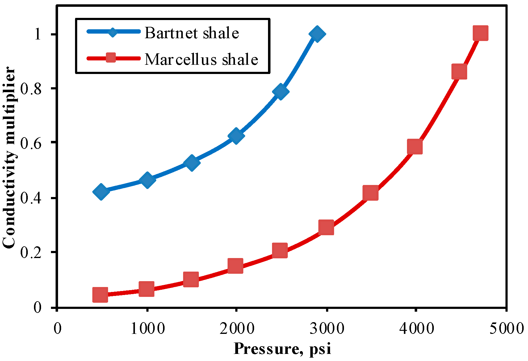
Figure 4.
Comparison of the results of the present proposed model and the traditional models.

Figure 5.
Comparison between filed data and simulation results in Marcellus Shale.
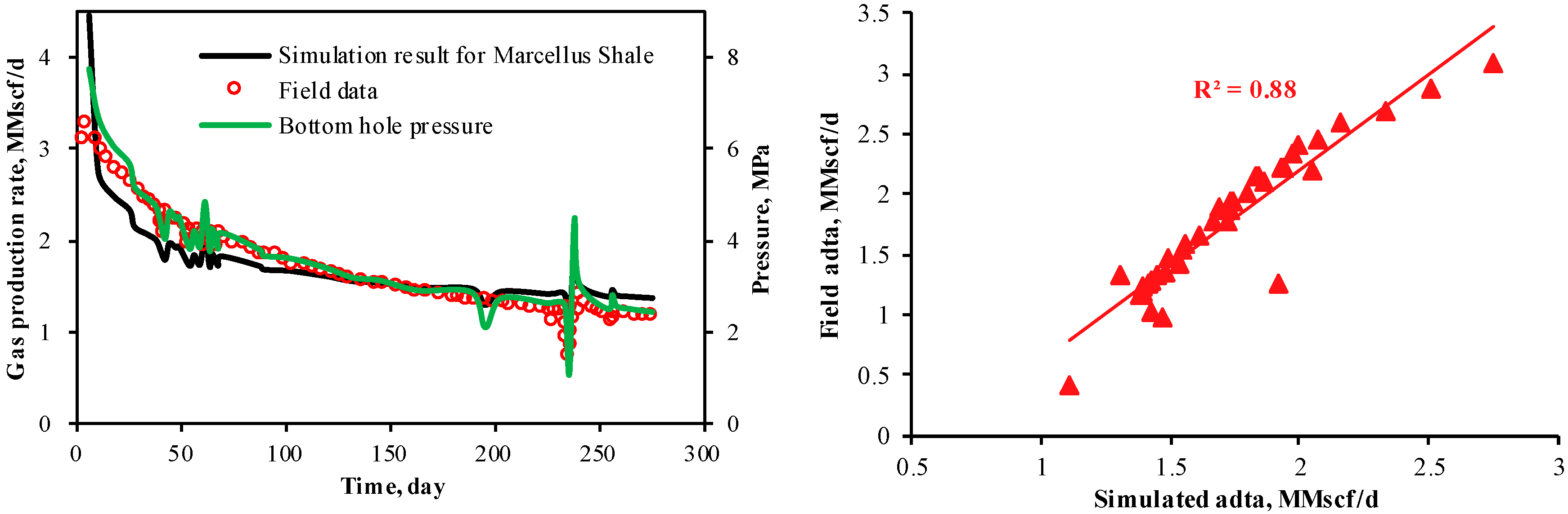
Figure 6.
Relationships between mass flux in various flow regimes and reservoir pressure.

Figure 7.
Effect of pore size on gas flow capacity.

Figure 8.
(a) Effect of pore size on gas flow of slip flow; (b) effect of pore size on gas flow of Knudsen diffusion.
Figure 8.
(a) Effect of pore size on gas flow of slip flow; (b) effect of pore size on gas flow of Knudsen diffusion.

Figure 9.
Effect of adsorption/desorption on slip flow regime. (a) Mass flux deviation with respect to pressure; (b) mass flux evolution with respect to pressure.
Figure 9.
Effect of adsorption/desorption on slip flow regime. (a) Mass flux deviation with respect to pressure; (b) mass flux evolution with respect to pressure.

Figure 10.
Effect of adsorption/desorption on Knudsen diffusion. (a) Mass flux deviation with respect to pressure; (b) mass flux evolution with respect to pressure.
Figure 10.
Effect of adsorption/desorption on Knudsen diffusion. (a) Mass flux deviation with respect to pressure; (b) mass flux evolution with respect to pressure.

Figure 11.
Effect of adsorption/desorption on surface diffusion. (a) Mass flux deviation with respect to pressure; (b) mass flux evolution with respect to pressure.
Figure 11.
Effect of adsorption/desorption on surface diffusion. (a) Mass flux deviation with respect to pressure; (b) mass flux evolution with respect to pressure.

Figure 12.
Effect of adsorption/desorption on total mass flux. (a) Mass flux deviation with respect to pressure; (b) mass flux evolution with respect to pressure.
Figure 12.
Effect of adsorption/desorption on total mass flux. (a) Mass flux deviation with respect to pressure; (b) mass flux evolution with respect to pressure.
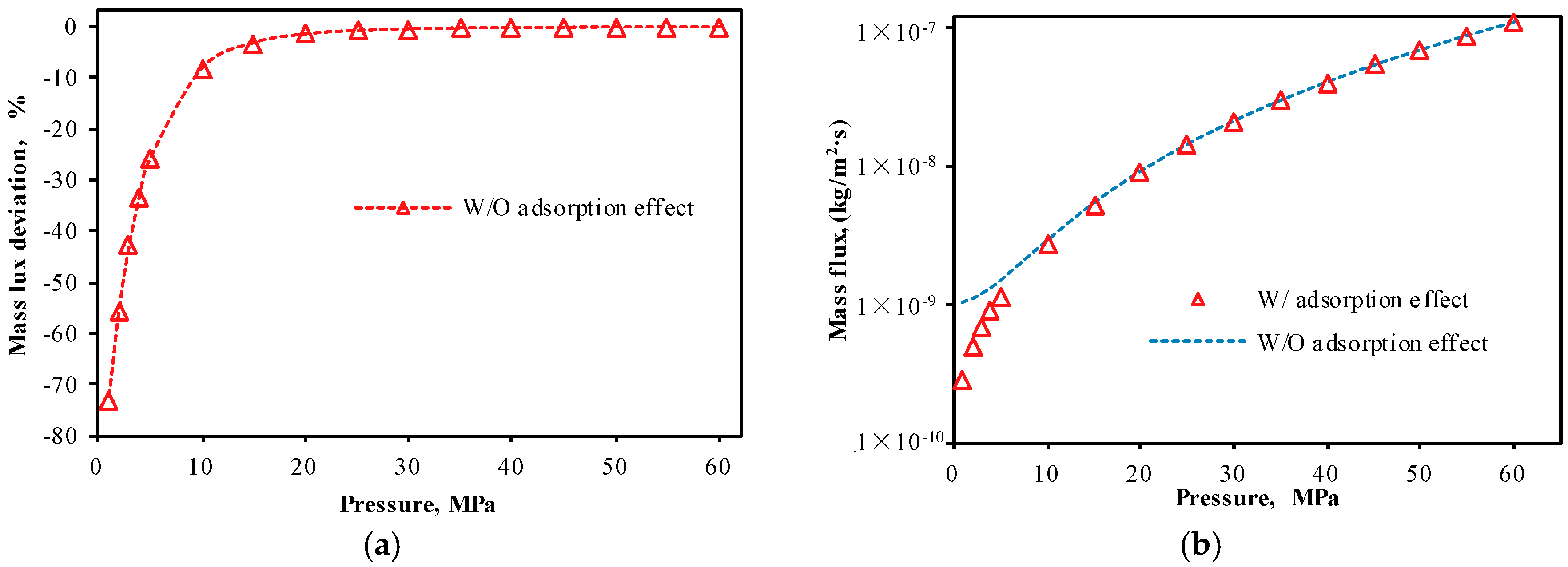
Figure 13.
Effect of stress-sensitivity on continuum regime. (a) Mass flux deviation with respect to pressure; (b) mass flux evolution with respect to pressure.
Figure 13.
Effect of stress-sensitivity on continuum regime. (a) Mass flux deviation with respect to pressure; (b) mass flux evolution with respect to pressure.

Figure 14.
Effect of stress-sensitivity on slip flow regime. (a) Mass flux deviation with respect to pressure; (b) mass flux evolution with respect to pressure.
Figure 14.
Effect of stress-sensitivity on slip flow regime. (a) Mass flux deviation with respect to pressure; (b) mass flux evolution with respect to pressure.
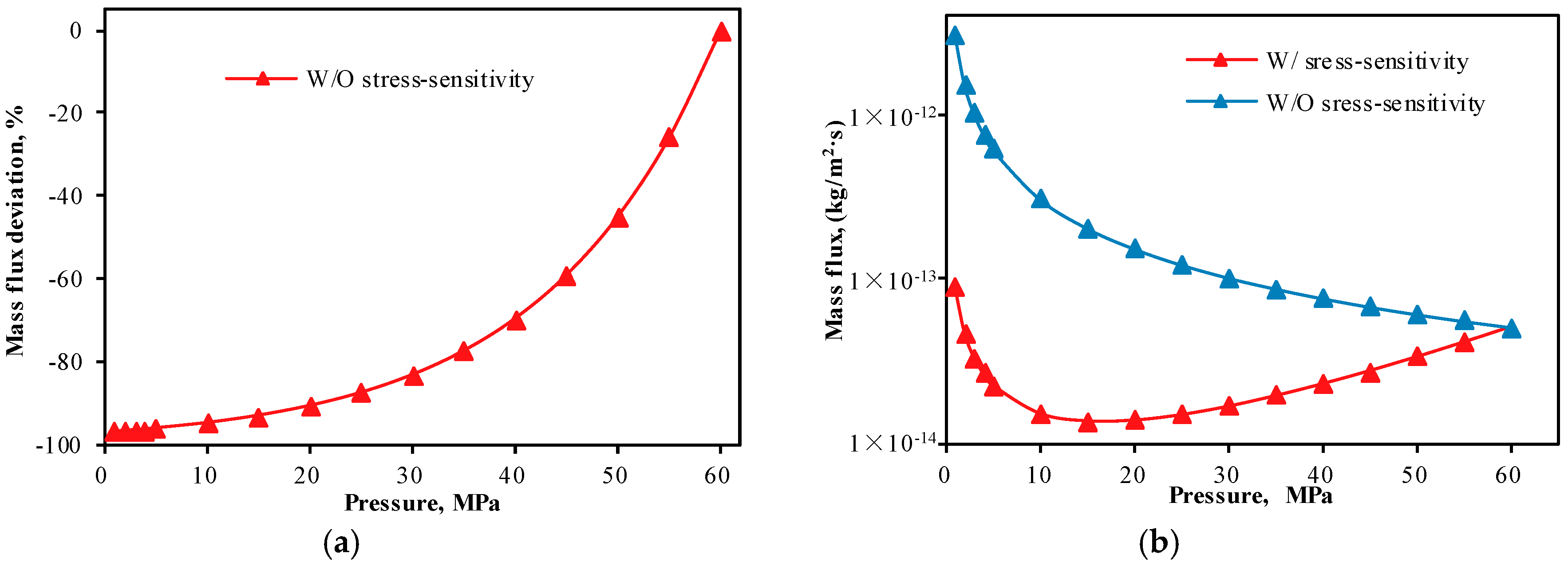
Figure 15.
Effect of stress-sensitivity on Knudsen diffusion. (a) Mass flux deviation with respect to pressure; (b) mass flux evolution with respect to pressure.
Figure 15.
Effect of stress-sensitivity on Knudsen diffusion. (a) Mass flux deviation with respect to pressure; (b) mass flux evolution with respect to pressure.

Figure 16.
Effect of stress-sensitivity on total mass flux. (a) Mass flux deviation with respect to pressure; (b) mass flux evolution with respect to pressure.
Figure 16.
Effect of stress-sensitivity on total mass flux. (a) Mass flux deviation with respect to pressure; (b) mass flux evolution with respect to pressure.

Figure 17.
Comparison of the impacts of adsorption/desorption and stress-sensitivity on total muss flux.
Figure 17.
Comparison of the impacts of adsorption/desorption and stress-sensitivity on total muss flux.


Table 1.
Main parameters for reservoir simulation of Marcellus Shale.
| Parameters | Value | Unit |
|---|---|---|
| Reservoir depth | 2619.1 | m |
| Initial reservoir pressure gradient | 1.40 × 10⁴ | Pa/m |
| Initial reservoir pressure | 3.26 × 10⁷ | Pa |
| Reservoir temperature | 352.55 | K |
| Gas viscosity | 2.01 × 10⁻⁵ | Pa·s |
| Initial matrix permeability | 0.0006 | mD |
| Initial hydraulic fracture permeability | 30 | mD |
| Initial matrix porosity | 0.065 | fraction |
| Surface diffusion coefficient | 1.0 × 10⁻⁸ | m2/s |
| Langmuir pressure | 3.0 × 10⁶ | Pa |
| Langmuir volume | 2.5 | m3/t |
| Initial gas saturation | 0.70 | fraction |
| Drainage Area | 80 | acres |
| Wellbore radius | 0.3646 | ft |
| Number of fractures | 17 | Dimensionless |
| Horizontal well length | 426.7 | m |
Table 2.
Main parameters for reservoir simulation.
| Parameters | Value | Unit |
|---|---|---|
| Reservoir depth | 2500 | m |
| Initial reservoir pressure gradient | 1.0 × 10⁴ | Pa/m |
| Initial reservoir pressure | 6.0 × 10⁷ | Pa |
| Reservoir temperature | 323 | K |
| Gas viscosity | 2.01 × 10⁻⁵ | Pa·s |
| Initial matrix porosity | 0.06 | fraction |
| Initial permeability | 0.006 | mD |
| Pore tortuosity factor | 1.5 | fraction |
| Compressibility for permeability | 6.0 × 10⁻⁷ | Pa−1 |
| Compressibility for porosity | 4.0 × 10⁻⁷ | Pa−1 |
| Pore area fractal dimension | 1.8 | fraction |
| Langmuir pressure | 3.0 × 10⁶ | Pa |
| Langmuir volume | 2.5 | m3/t |
© 2018 by the authors. Licensee MDPI, Basel, Switzerland. This article is an open access article distributed under the terms and conditions of the Creative Commons Attribution (CC BY) license (http://creativecommons.org/licenses/by/4.0/).
Share and Cite
MDPI and ACS Style
Hou, X.; Zhu, Y.; Liu, Y.; Wang, Y. A Fully Coupled Model for the Simulation of Gas Flow in Multiscale Shale Reservoirs Combining Multiple Effects. Appl. Sci. 2018, 8, 1063. https://doi.org/10.3390/app8071063
AMA Style
Hou X, Zhu Y, Liu Y, Wang Y. A Fully Coupled Model for the Simulation of Gas Flow in Multiscale Shale Reservoirs Combining Multiple Effects. Applied Sciences. 2018; 8(7):1063. https://doi.org/10.3390/app8071063
Chicago/Turabian StyleHou, Xiaowei, Yanming Zhu, Yu Liu, and Yang Wang. 2018. "A Fully Coupled Model for the Simulation of Gas Flow in Multiscale Shale Reservoirs Combining Multiple Effects" Applied Sciences 8, no. 7: 1063. https://doi.org/10.3390/app8071063
Note that from the first issue of 2016, this journal uses article numbers instead of page numbers. See further details here.