Research on the Principle of a New Flexible Screw Conveyor and Its Power Consumption

 ,
,
Abstract
:1. Introduction
2. Analysis of the Mechanical Properties of a Single Flexible Blade
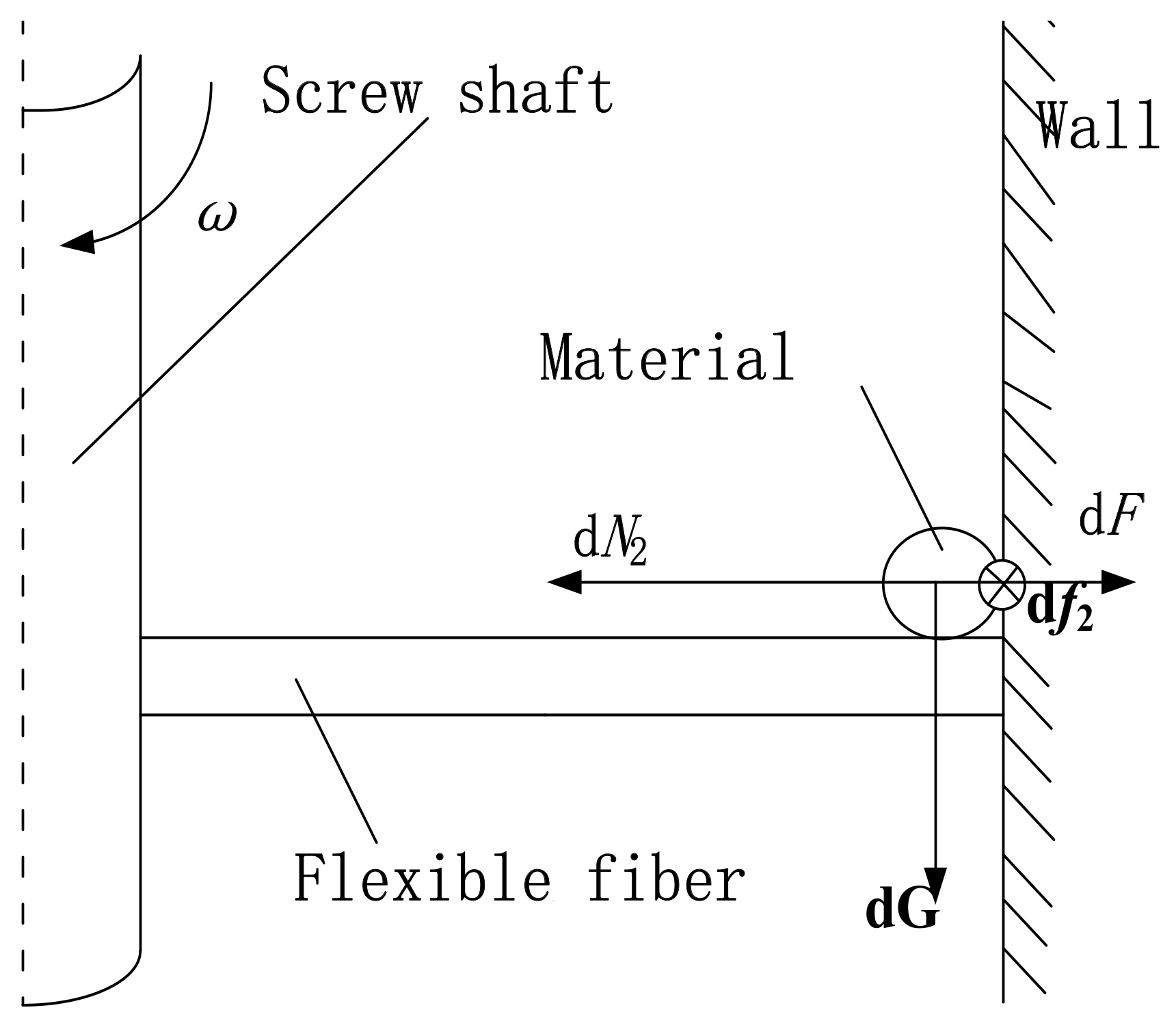
2.1. The Radial Analysis of a Single Blade
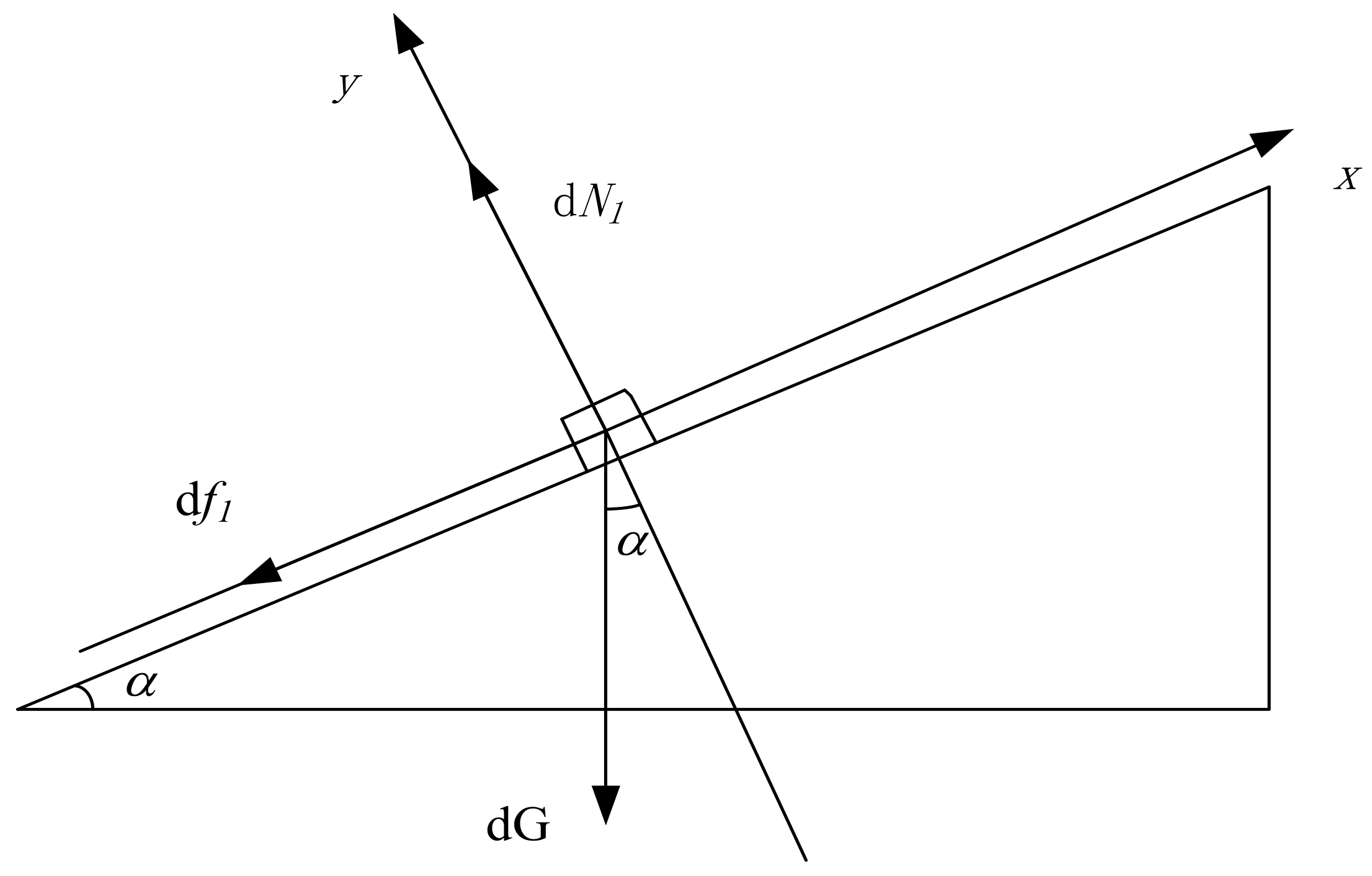
2.2. The Axial Analysis of a Single Blade
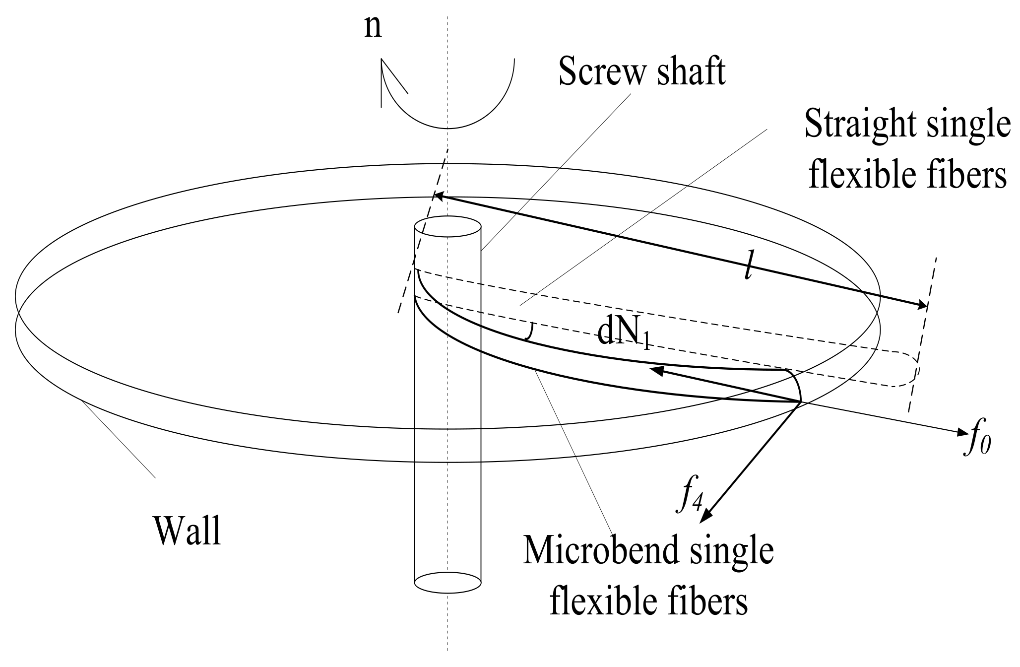
2.3. The Structural Parameters Analysis of the Flexible Blade
2.4. The Flexible Blade Discrete Coefficient
3. The Conveying Power Consumption Model
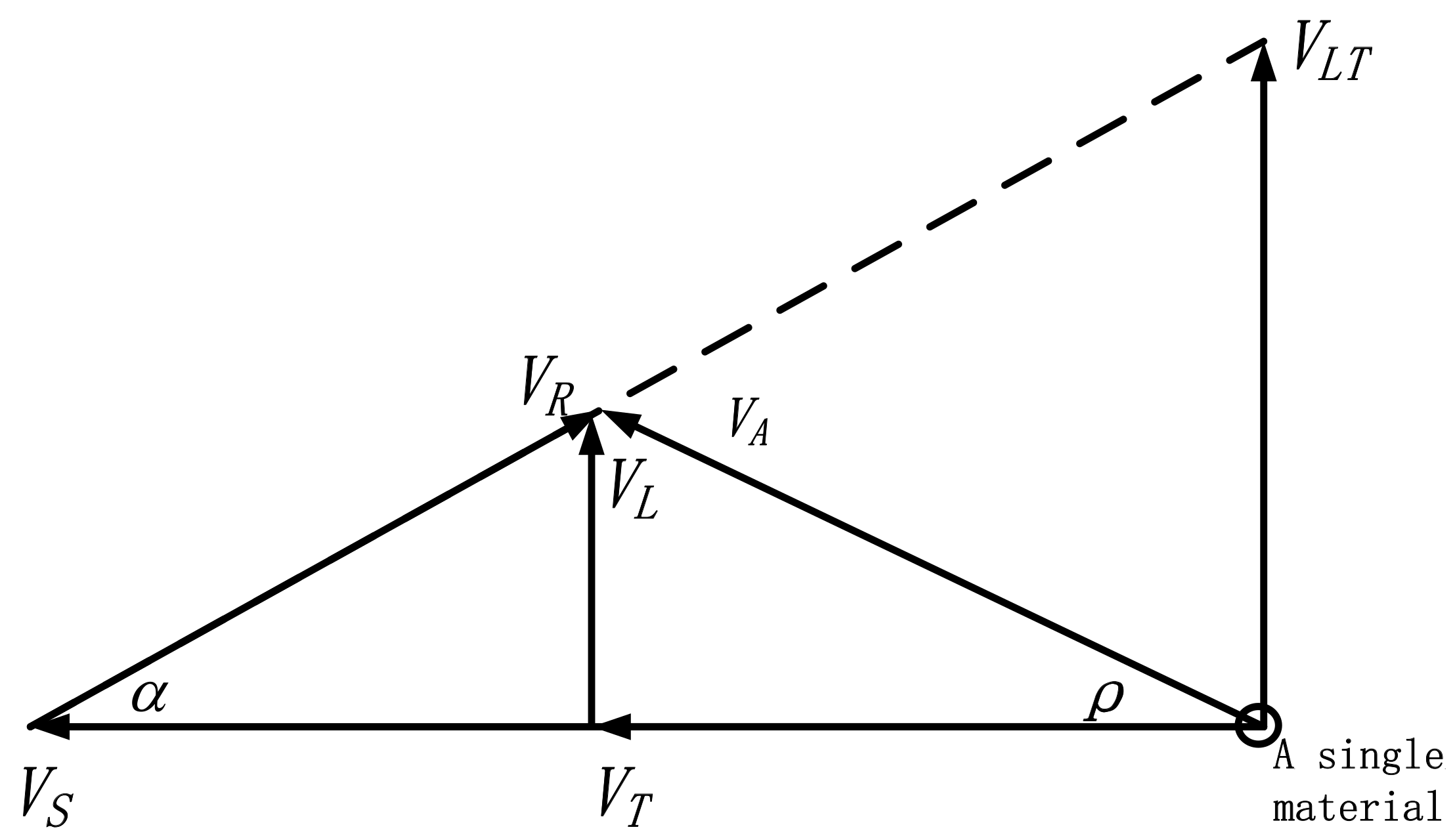
3.1. Single Particle Motion Analysis
3.2. Power Consumption Calculation
4. Discrete Element Simulation
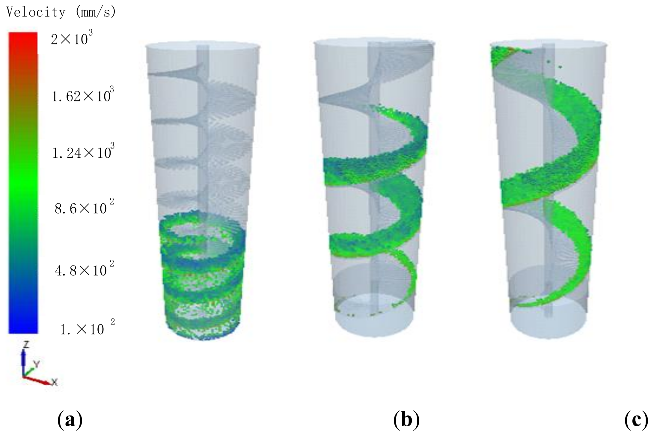
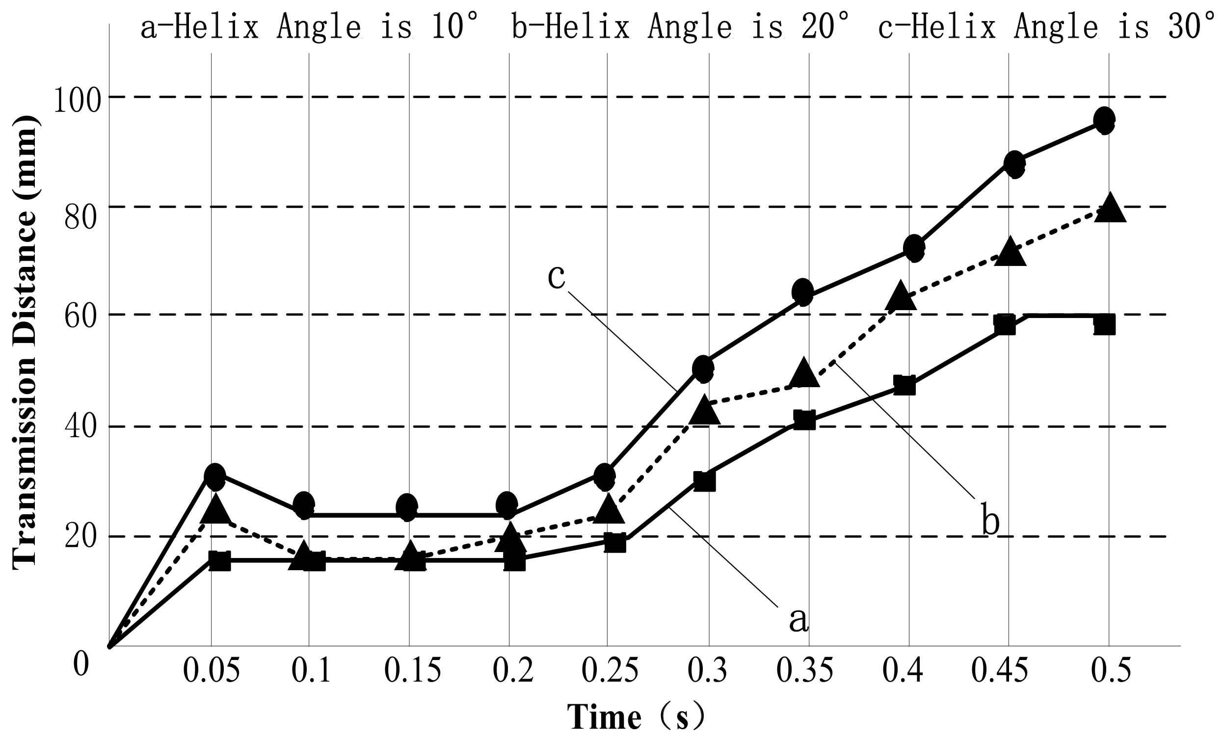
4.1. The Spiral Angle
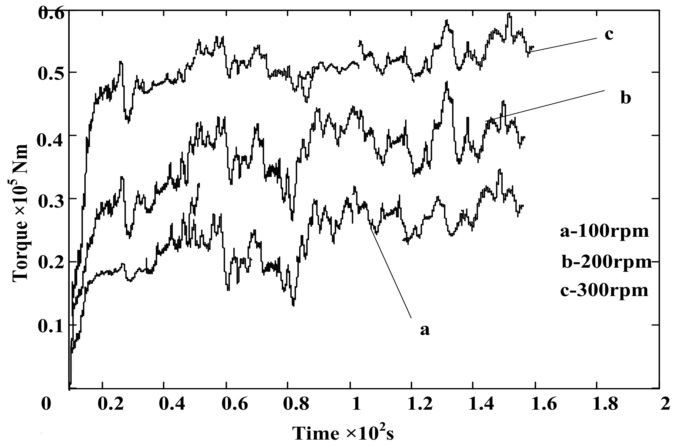
4.2. The Different Rotary Speed
5. Test and Results
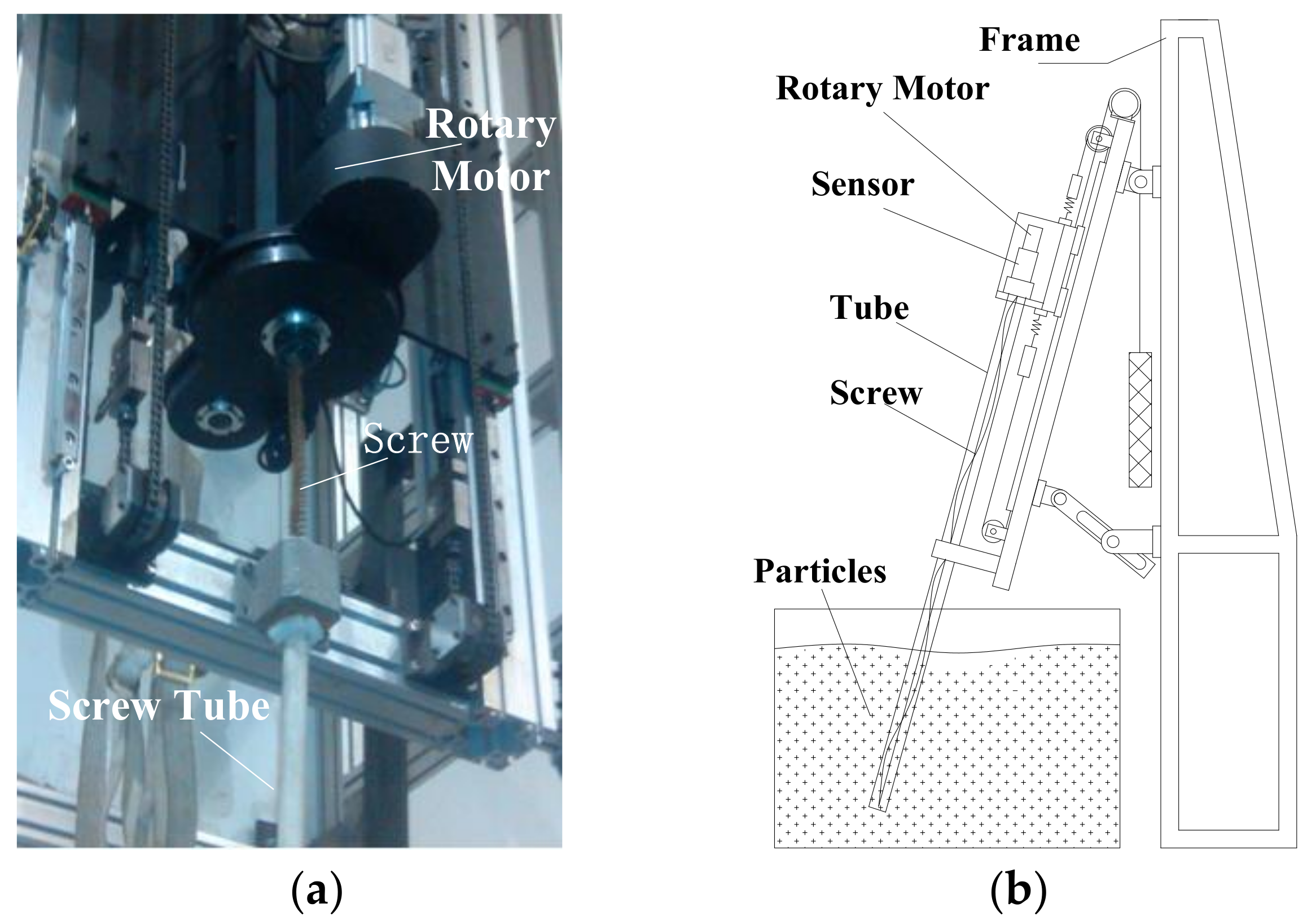
5.1. Experiments
5.2. Results
6. Conclusions
- (1)
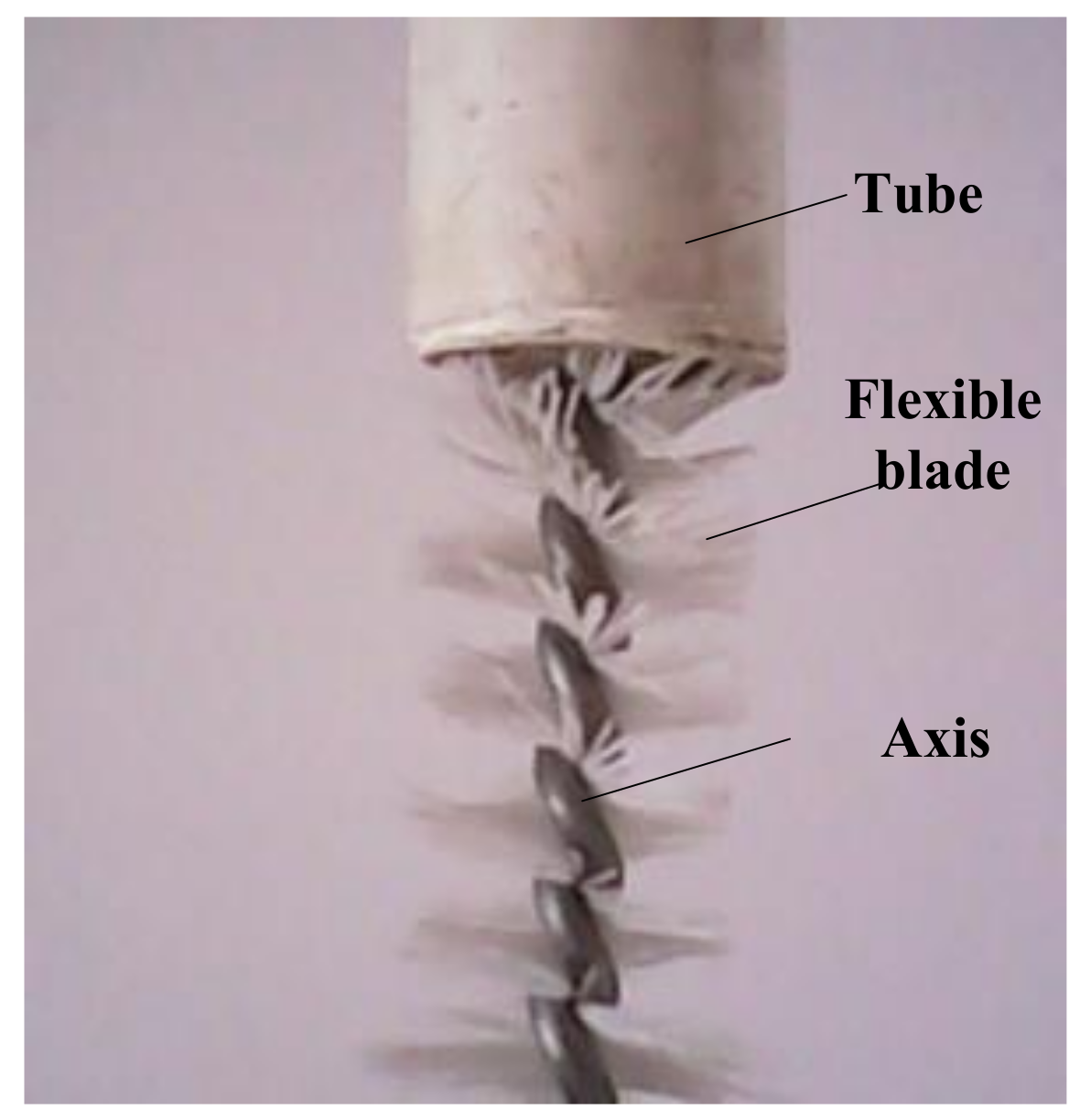
- A flexible screw blade which is made of flexible fiber bundles is proposed as the spiral conveying shaft of screw conveyor for powder conveying. The ability to transmit particles whose diameter is bigger than that of the flexible fibers is verified by experiments.
- (2)
- According to the theory of particle mechanics and material mechanics, the power consumption and conveying quantity model of flexible screw blades for conveying bulk materials are established. The main parameters affecting the conveying amount and power consumption are: helical diameter, spiral rising angle, blade dispersion coefficient, and so on.
- (3)
- The mechanism of flexible spiral blade conveyor is verified by the particle material mechanics software EDEM. From the results of the simulation, we show that the conveying capacity of the particles decreases with the acceleration of the clearance of the flexible helical blades and increases with the speed, diameter, and angle of the screw conveyer; the power consumption of the particle material increases with the speed of the screw conveyor and the diameter of the spiral.
- (4)
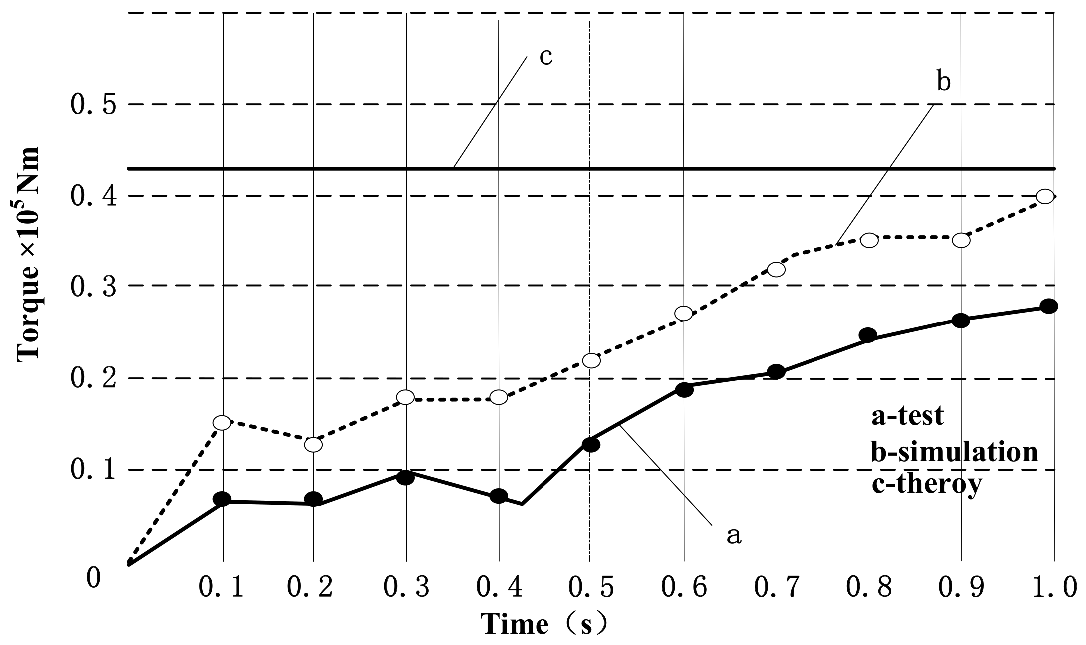
- The theoretical and simulation results are verified by experiments. By comparing the power (torque) curves at the same speed, the growth trend of the experimental curves is consistent with the results of the theoretical analysis and simulation curves.
Author Contributions
Acknowledgments
Conflicts of Interest
References
- Wang, D.-X. Research on Numerical Analysis and Optimal Design of the Screw Conveyor. Univ. Technol. 2012, 27, 32–36. [Google Scholar]
- Hevko, R.B.; Rozum, R.I.; Klendii, O.M. Development of Design and Investigation of Operation Processes of Loading Pipes of Screw Conveyors. Agric. Eng. 2016, 3, 200–210. [Google Scholar]
- Hu, K. Screw conveyor principle and design. J. Nanchang Univ. (Engl. Ed.) 2000, 4, 30–36. [Google Scholar]
- Mondal, D. Study on filling factor of short length screw conveyor with flood-feeding condition. Mater. Today Proc. 2018, 5, 1286–1291. [Google Scholar] [CrossRef]
- Qi, J.; Meng, H.; Kan, Z.; Li, C.; Li, Y. Analysis and test of feeding performance of dual-spiral cow feeding device based on EDEM. Trans. Chin. Soc. Agric. Eng. 2017, 33, 65–71. [Google Scholar]
- Zhao, W.-M.; Li, G.-X. Screw Drill Test for Soil Delivering Speed and Resistance. Constr. Mach. 2006, 37, 23–25. [Google Scholar]
- David, R. Gill Basics of Flexible Screw Conveyors. Plant Eng. 2003, 25, 232–235. [Google Scholar]
- Spiroflow Clitheroe Lances. Flexible Screw solves sticky problem. Prof. Eng. 2002, 45, 118–121. [Google Scholar]
- Xu, D.-W.; Liu, G.-B.; Cheng, D.-W. Design and Construction of the TPS310 Screw Conveyor. Packag. Food Mach. 2002, 20, 35–37. [Google Scholar]
- Liu, Z.-K.; Liu, Y.-Z. Analysis and Calculation of Powder of Screw Conveyor. Feed Ind. 1987, 5, 32–36. [Google Scholar]
- Huang, S.-Y. Mechanics of Granular; Machinery Industry Press: Beijing, China, 1993; pp. 42–45. [Google Scholar]
- Kapur, P.C.; Meloy, T.P. Industrial Modeling of Spirals for Optimal Configuration and Design: Spiral Geometry, Fluid Flow and Forces on Particles. Powder Technol. 1999, 102, 244–252. [Google Scholar] [CrossRef]
- Woodcock, C.R.; Mason, J.S. Bulk Soilds Handling; Black & Son Limited: London, UK, 1987. [Google Scholar]
- Uchida, K.; Okamoto, K. Measurement Technique on the Diffusion Coefficient of Powder Flow in a Screw Feeder by X-ray Visualization. Powder Technol. 2008, 187, 138–145. [Google Scholar] [CrossRef]
- Lv, B.-Y. Manufacturing and forming technology of the blade of a screw conveyer. For. Mach. Woodwork. Equip. 2009, 37, 49–51. [Google Scholar]
- Roberts, A.W. Design and Performance Criteria for Screw Conveyors in Bulk Solides Operation. Bulk Solids Handl. 2002, 22, 436–444. [Google Scholar]
- Morton, W.E.; Hearle, J.W.S. Physieal Properties of Textile Fibres, 2nd ed.; William Heinemann Ltd.: London, UK, 1975; pp. 399–440. [Google Scholar]
- Xu, Y.; Sun, Q.-C.; Zhang, L. Research Progress on Particle Discrete Element Method. Adv. Mech. 2003, 33, 251–256. [Google Scholar]
- Sun, L.-M. Research on the Current Situation and Development of Mechanics of Granular. J. Kaifeng Univ. 2011, 25, 74–77. [Google Scholar]
- Zhu, L.-T. The Mechanical Properties of the Fiber Strain Rate Effect and Knitted Composite Ballistic Impact Damage Mechanism. Donghua Univ. 2010, 6, 32–36. [Google Scholar]
- Yan, Z.-J. Study on structural change of fiber and its composites mechanical properties and fracture process. Synth. Fiber 2010, 28, 46–48. [Google Scholar]
- Li, J.-H.; Fu, C.-M.; Xia, P. Optimization Design of Screw Conveyor Mode Based on Simulation. Mech. Sci. Technol. 2011, 30, 512–516. [Google Scholar]
- Tian, Y.; Deng, Z.-Q.; Tang, D.-W. Structure Parameters Optimization and Simulation Experiment of Auger in Lunar Soil Drill-sampling Device. Chin. J. Mech. Eng. 2012, 48, 10. [Google Scholar] [CrossRef]


| Material | Poisson’s Ratio | Modulus of Elasticity (pa) | Density (kg/m3) |
|---|---|---|---|
| Starch | 0.25 | 2 × 10⁷ | 1500 |
| Nylon 66 | 0.28 | 3.2 × 10⁹ | 1130 |
| PVC | 0.35 | 3 × 10⁶ | 1400 |
| Interaction | Coefficient of Restitution | Static Friction Coefficient | Rolling Friction Coefficient |
|---|---|---|---|
| Particle to particle | 0.1 | 0.7 | 0.01 |
| Particles to nylon | 0.3 | 0.5 | 0.01 |
| Particles to PVC tube | 0.3 | 0.5 | 0.01 |
| Interaction | Model |
|---|---|
| Particle to particle | Mertz–Mindin with bonding built-in |
| Particles to nylon | Mertz–Mindin (no slip) built-in |
| Particles to PVC tube | Mertz–Mindin (no slip) built-in |
© 2018 by the authors. Licensee MDPI, Basel, Switzerland. This article is an open access article distributed under the terms and conditions of the Creative Commons Attribution (CC BY) license (http://creativecommons.org/licenses/by/4.0/).
Share and Cite
Tian, Y.; Yuan, P.; Yang, F.; Gu, J.; Chen, M.; Tang, J.; Su, Y.; Ding, T.; Zhang, K.; Cheng, Q. Research on the Principle of a New Flexible Screw Conveyor and Its Power Consumption. Appl. Sci. 2018, 8, 1038. https://doi.org/10.3390/app8071038
Tian Y, Yuan P, Yang F, Gu J, Chen M, Tang J, Su Y, Ding T, Zhang K, Cheng Q. Research on the Principle of a New Flexible Screw Conveyor and Its Power Consumption. Applied Sciences. 2018; 8(7):1038. https://doi.org/10.3390/app8071038
Chicago/Turabian StyleTian, Ye, Panpan Yuan, Fei Yang, Jihai Gu, Mengmeng Chen, Junyue Tang, Yilin Su, Tianxiang Ding, Kailiang Zhang, and Qiang Cheng. 2018. "Research on the Principle of a New Flexible Screw Conveyor and Its Power Consumption" Applied Sciences 8, no. 7: 1038. https://doi.org/10.3390/app8071038