Micromechanical Multiscale Modeling of ITZ-Driven Failure of Recycled Concrete: Effects of Composition and Maturity on the Material Strength


BATir Department, ULB—Université libre de Bruxelles, CP194/4, 87 Avenue A. Buyl, 1050 Brussels, Belgium
*
Author to whom correspondence should be addressed.
Appl. Sci. 2018, 8(6), 976; https://doi.org/10.3390/app8060976
Submission received: 17 April 2018
/
Revised: 5 June 2018
/
Accepted: 7 June 2018
/
Published: 14 June 2018
(This article belongs to the Special Issue Modelling of Early Age Cracking Risks and Serviceability of Concrete Structures)
Abstract
:Recycled concrete, i.e., concrete which contains aggregates that are obtained from crushing waste concrete, typically exhibits a smaller strength than conventional concretes. We herein decipher the origin and quantify the extent of the strength reduction by means of multiscale micromechanics-based modeling. Therefore, the microstructure of recycled concrete is represented across four observation scales, spanning from the micrometer-sized scale of cement hydration products to the centimeter-sized scale of concrete. Recycled aggregates are divided into three classes with distinct morphological features: plain aggregates which are clean of old cement paste, mortar aggregates, and aggregates covered by old cement paste. Macroscopic loading is concentrated via interfacial transition zones (ITZs)—which occur mutually between aggregates, old, and new cement paste—to the micrometer-sized hydrates resolved at the smallest observation scale. Hydrate failure within the most unfavorably loaded ITZ is considered to trigger concrete failure. Modeling results show that failure in either of the ITZs might be critical, and that the failure mode is governed by the mutual stiffness contrast between aggregates, old, and new paste, which depend, in turn, on the concrete composition and on the material’s maturity. The model predicts that the strength difference between recycled concrete and conventional concrete is less pronounced (i) at an early age compared to mature ages, (ii) when the old cement paste content is small, and (iii) when recycling a high-quality parent concrete.
1. Introduction
The uniaxial compressive strength of recycled concrete, i.e., concrete which contains aggregates produced by crushing waste concrete, is typically smaller than the strength of conventional concrete [1,2,3,4,5,6]. The extent of the strength reduction depends on several factors including the replacement ratio of natural by recycled aggregates [1,6], the strength of the parent concrete [7,8,9], the water-to-cement ratio of the new mix [1,8], the maturity [9,10], the saturation state of the recycled aggregates [9], the mixing method [11,12], and the curing conditions [13]. In order to design recycled concrete compositions that can compete with conventional concretes, and this way to aim towards a more sustainable construction process, knowledge on the micromechanical origin of the experimentally observed strength loss is crucial.
The failure mechanism of conventional concrete under uniaxial compressive loading is well understood: concrete failure is governed by cracking in the “weakest link” of its microstructure, the so-called interfacial transition zones (ITZs) between aggregates and cement pastes [14,15]. As for recycled concrete, however, ITZs do not only occur between aggregates and the (new) cement paste, but also between the old and the new cement paste and even“within” the recycled aggregate, i.e., between the old aggregate and the old cement paste. Experimental identification of the failure-governing ITZs is thus significantly more challenging and mostly limited to visual inspection of crushed concrete samples. This way, cracking in plate-type concrete specimens containing cylindrical recycled aggregates (natural aggregate core with old cement paste cover) is observed to occur around both the ITZ between aggregates and old mortar and between old and new mortar [16]. By analyzing the fracture surface after crushing a recycled concrete specimen, Liu et al. [17], however, showed that cracks through the old mortar-new mortar interfaces rarely occur; instead, cracking through aggregate-mortar (old and new) ITZs is likely. Otsuki et al. [8] coupled strength measurements with microhardness tests of the ITZs between aggregates and the old and new mortar, respectively. They observed that, when preparing recycled concrete with high-strength new cement paste associated with high-strength ITZs between aggregates and new cement paste, cracks concentrate within the ITZs between aggregates and old mortar. In case of a low-strength new cement paste, the cracks, however, concentrate within the (low-strength) ITZ between aggregates and new cement paste. Then, the strength of the old mortar does not affect the macroscopic strength of concrete. These experimental observations underline that either of the ITZs might represent the “weakest link” of the microstructure of recycled concrete.
The identification of failure-governing ITZs calls for micromechanics-based modeling approaches, since they allow for quantification of the ITZ-related microstresses as a function of the stiffness contrasts between old cement paste, new cement paste, and aggregates. Such modeling techniques have resulted in interesting insights on ITZ failure modes of conventional concretes [18,19] and eventually led to very successful micromechanics-based strength predictions [20,21]. As for recycled concrete, neither critical microstress states in the different ITZs nor micromechanics-based strength predictions are, to the authors’ knowledge, available in the open literature. We herein aim at closing this gap by applying 3D multiscale modeling in the framework of continuum micromechanics [22]. Continuum micromechanics modeling approaches were applied very successfully to decipher the mix- and age-dependent material behavior of cement paste, mortar, and concrete in the context of homogenization of elastic [23,24], creep [25,26], and thermal material properties [27], as well as of autogenous shrinkage strains [28]. Pichler and Hellmich [29] and Pichler et al. [30] showed that the uniaxial compressive strength of cement paste can be very accurately predicted by means of quasi-brittle strength upscaling starting from the micrometer-sized scale of the hydrates (the hydration products which form during the chemical reaction of cement clinker with water). Brittle material failure of any sub-portion of the hydrate phase was considered to trigger the failure at the macroscopic scale of cement paste. This concept was very recently extended to conventional concrete by explicitly accounting for ITZ-driven stress concentrations [21,31], and we herein extend it further towards modeling the compressive strength of recycled concrete. This way, we aim for deciphering the critical ITZs, quantify the local stress states and study the sensitivity of the model-predicted macroscopic strength with respect to changes in mix design (such as recycled aggregate replacement ratio, water-to-cement ratio) and age.
This paper is structured as follows: Section 2 deals with model development, in particular with the envisaged micromechanical representation of recycled concrete and the ITZ-related microscopic failure criteria. This is followed by the presentation of the model results and their discussion in the context of sensitivity analysis regarding the recycled concrete composition and the maturity (Section 3). In Section 4, key model assumptions and corresponding limitations are discussed and in Section 5, the paper is closed with conclusions.
2. Model Development
2.1. Micromechanical Representation of Recycled Concrete
The microstructure of recycled concrete is resolved across four length scales by means of four hierarchically-organized representative volume elements (RVEs) (see Figure 1). Separation of scales [22] is fulfilled in the sense that all RVEs are (i) significantly smaller than the structures which they form and (ii) significantly larger than the inhomogeneities inside the RVEs. As the inhomogeneities within those four RVEs are to complex to be described in full detail, quasi-homogeneous sub-domains (so-called material phases) are introduced and their micromechanical features such as shape, volume dosage, mechanical properties, and their mutual interactions are discussed next.
At the largest observation scale, the centimeter-sized concrete scale, we consider a matrix phase of new cement paste hosting (natural and recycled) aggregate phases (see Figure 1a). The morphological complexity of recycled aggregates renders their representation in the micromechanical approach a challenging task. We herein aim for a representation which is able to capture the peculiarities of the (micro-)stress fields within and around typical recycled aggregates of various morphologies, while still allowing for multiscale homogenization in the framework of continuum micromechanics. Based on visual inspection of typical recycled aggregates which were used in the study of Bendimerad et al. [32], we distinguish three classes of recycled aggregates (see Figure 2):
- A considerable fraction of the recycled aggregates are either completely free of attached mortar or cement paste covers only a negligible part of their surfaces. Recycled aggregates that exhibit such a morphology are herein labeled as class I aggregates.
- A considerable fraction of the recycled aggregates are old mortar particles where none of the many small aggregates inside the mortar exhibits a dominant size, labeled herein as class II aggregates.
- A considerable fraction of the recycled aggregates are single stone aggregates, whereby the majority of the aggregate surface is covered by cement paste, labeled herein as class III aggregates.
Classification is not straightforward, in particular the distinction between class II and class III recycled aggregates, given that one cannot see “inside” the cement paste (or mortar) inclusions. In this context, we report on a study by Liu et al. [17], who manufactured recycled concrete using ordinary (gray) Portland cement and recycled aggregates from a concrete produced with white cement paste. This way, the authors could readily distinguish the old (gray) and new (white) cement paste by means of image analysis of cut sections (see Figure 3a,b). The resulting images support the aforementioned classification of the recycled aggregates, as exemplarily demonstrated in Figure 3b. Notably, yet another important recycled aggregate morphology might be identified: recycled aggregates composed of a one or a few large stones with old cement paste attached or in between, whereby both stones and paste are visible in comparable proportions at the boundary (see e.g., the pictures of [33]). Herein, we do not explicitly account for such a morphology, given the applied scale separation-based homogenization approach. Rather, we consider that the stress fields inside and around such recycled aggregates are captured well by means of the three envisaged classes of recycled aggregates.
Next, we discuss how the three aggregate morphology classes are translated to micromechanical phases. Class I recycled aggregates (old plain aggregates) as well as (potentially used) new natural (virgin) aggregates are modeled as spherical inclusions, see Figure 3c, analogously to earlier micromechanics models [21,23]. Notably, these phases represent both coarse aggregates and sand particles. Class II recycled aggregates (old mortar aggregates) are idealized as spherical homogeneous phase at the scale of concrete. Their heterogeneity is resolved on a smaller scale of observation (see Figure 3b). At the old mortar-related observation scale, we envision a 1 cm-large RVE to contain a spherical aggregates phase (referred to as old embedded aggregates) which is surrounded by an old cement paste matrix phase. We are left with discussing the class III recycled aggregates at the scale of recycled concrete. They are represented by means of a spherical layered inclusion phase consisting of an aggregate core (labeled as old covered aggregate) and a cover built up of old cement paste. In summary, the RVE of recycled concrete comprises four distinct aggregate phases (one of them represents new natural aggregates and the remaining three represent the three old recycled aggregates classes) and a cement paste matrix phase. Given the matrix-inclusion type character of the RVE of recycled concrete and of old mortar, respectively, a Mori–Tanaka scheme [34] is appropriate for homogenization.
Finally, we discuss the RVEs of cement paste and hydrate foam, for which we use the well-established micromechanical representation developed from Pichler and Hellmich [29]. The microstructure of ordinary Portland cement paste, i.e., either the microstructure old cement paste which covers or embeds the old aggregates, or the one of the new cement paste matrix, is resolved at a scale of 1 mm (see the RVE in Figure 1c). We envision that the RVE of cement paste consists of spherical unhydrated clinker phases which are embedded in a hydrate foam matrix phase. Again, the RVE is modeled by means of the Mori–Tanaka scheme. The hydrate foam, in turn, is resolved at a micron-sized observation scale (see Figure 1d). Its microstructure is considered to consist of spherical capillary pore phases (either water-filled pores or air pores due to hydration-induced shrinkage) and hydrate needle phases which are uniformly oriented in all space directions. The self-consistent scheme [35,36] is used for homogenization at this scale in order to take mutual interactions between hydrates and pores into account. Failure of the needle-shaped hydrates at this scale is considered to trigger macroscopic material failure, as discussed next.
2.2. Modeling of Hydrate Failure in Critical ITZs
We follow Pichler and Hellmich [29] and consider that if the most unfavorably loaded hydrate needle fails, recycled concrete will fail as well (quasi-brittle strength upscaling). Hydrate failure is modeled by means of a Drucker–Prager criterion, reading as [21]
whereby and denote the Drucker–Prager constants of the hydrates. Based on nanoindentation tests combined with limit state analysis [37], these parameters were identified for ordinary Portland cement paste as [21]
In Equation (1),
and denote volumetric and deviatoric stress measures which trigger hydrate failure. As for their determination, we first report on the situation in ordinary concrete. Driven by the stiffness contrast between aggregates and cement paste, the local microstresses states in the ITZs around the aggregates are larger than in the bulk of the cement paste [18,19]. The cement paste RVEs hosting the most unfavorably loaded hydrates are therefore located within the ITZs of conventional concrete, i.e., in the immediate vicinity of the aggregate surfaces [21]. As for recycled concrete, the situation is more complex. In RVEs of recycled both concrete and old mortar according to Figure 1a,b, respectively, contain ITZs. Six potentially critical ITZs—with six associated failure modes—may be identified (see Figure 4):
- the ITZ between the new natural aggregates and the new cement paste matrix, herein labeled as , associated with failure as sketched in Figure 4a;
- the ITZ between the old plain aggregates and the new cement paste matrix, associated with failure as sketched in Figure 4b;
- the ITZ between the old mortar aggregates and the new cement paste matrix, associated with failure as sketched in Figure 4c;
- the ITZ between the old embedded aggregates and the old cement paste matrix inside the old mortar aggregates, associated with failure as sketched in Figure 4d;
- the ITZ between the old covered aggregates and the old cement paste cover, associated with failure as sketched in Figure 4e;
- the ITZ between the old cement paste cover and the new cement paste matrix, associated with failure as sketched in Figure 4f.
A priori determination of the critical failure mode is impossible. Rather, we have to “downscale” the macroscopic loading to microstress states acting in the hydrates of the individual ITZs and feed the Drucker–Prager failure criterion (1). The downscaling procedure involves two steps, (i) stress concentration from the macroscopic loading to microstresses of the aforementioned six ITZs, respectively, and (ii) further stress concentration from ITZ stresses to hydrate stresses, as discussed next.
2.3. Stress Downscaling to Hydrates via ITZs
We start with concentrating the macroscopic loading, which is imposed in terms of a homogeneous macroscopic stress state on the RVE of recycled concrete, down to the stress state prevailing in the six ITZs. Therefore, the macrostresses are first concentrated to phase stresses of the new natural aggregates (phase stresses denoted as ), of old plain aggregates (), and of old mortar aggregates (). Within the framework of our continuum micromechanics-based approach, the stress fields inside these aggregates are represented by homogeneous average microstresses, reading as
whereby stands for the fourth-order, concrete scale-related stress concentration tensor which is a function of the elastic phase properties and of the phase volume fractions (see Appendix A for an analytical set of formulas). The stress field of the old cement paste cover around the old covered aggregates, however, cannot be suitably represented by homogeneous microstresses. Rather, microstresses are position-dependent and read as
whereby both the stress state and the stress concentration tensor are functions of the position vector (see Appendix B for more details).
Next, the sought ITZ stress states are constructed, based on the phase stresses given in Equations (3) and (4). To obtain the ITZ stresses prevailing in the immediate vicinity around the new virgin aggregates (denoted as ), around the old plain aggregates (), and around the old mortar aggregates (), respectively, we consider a perfect bond in all interfaces, implying continuity conditions between displacements and tractions across the interfaces. Combining the continuity conditions with the isotropic elasticity law for the aggregate phase and the new cement paste, respectively, provides access to the sought ITZ stresses [18]. This procedure can be formalized by yet another stress concentration relation, reading as
whereby denotes the ITZ-specific stress concentration tensor. Next, we focus on the ITZ between the old embedded aggregates and the old cement paste matrix, which is located inside the RVE of mortar. First, we consider that the average stresses of the old mortar aggregates, according to Equation (3), take the role of the homogeneous macroscopic stresses and act at the boundary the RVE of old mortar according to Figure 1b. This allows us to downscale the stress states of the old mortar aggregates to average stresses in the old embedded aggregates , by analogy to stress concentration rule (3), according to
Considering perfect bond across yields, by analogy to interface stress concentration rule (3), the sought old embedded aggregate-related ITZ stresses as
The stress state of the ITZ between the old covered aggregates and the old cement paste, , simply follows from evaluating the stress field of the old cement paste cover according to Equation (4) for the location of the covered aggregate-old paste interface. Therefore, we introduce the dimensionless radial coordinate , which amounts to zero at the covered aggregate-old paste interface and to one at the old cement paste cover-new cement paste interface (see Appendix B for more details). This way, the sought ITZ stress in the immediate vicinity of the old covered aggregate reads as
Finally, the stress state of the ITZ between the old cement paste cover and the new cement paste matrix, labeled as can be obtained by applying the perfect bond-related interface stress concentration rule (5) to the stresses of the old cement paste cover evaluated at as
So far, we dealt with stress concentration relation at the millimeter-to-centimeter-sized concrete and mortar scales. Following earlier micromechanical approaches [18,19], the ITZs are considered as perfectly bonded 2D interface phases, rather than 3D phases at these scales. However, at the micrometer-sized cement paste scale, the ITZ’s microstructure is resolved according to Figure 1c. This way, the stress states according to Equations (5) and (7)–(9) can be considered as homogeneous macroscopic stress states imposed on an ITZ-related RVE of cement paste. Notably, the depicted microstructure is relevant for both the new cement paste as encountered in four of the six ITZs, namely in , , , and , and for the old cement paste encountered in the two remaining ITZs, namely in and . Concentrating the cement paste-related ITZ stresses further down to failure-relevant hydrate stress measures and , which enter the Drucke–Prager failure criterion (1), is discussed next. It has been shown by extensive model validation against independent experimental results that the second-order moments of microstresses of hydrates qualify as relevant stress measures for quantifying hydrate failure [21,29,30]. To get access to the second-order stress invariants, we follow the pioneering approach of Kreher [38] and consider that the elastic energy stored in the RVE can be expressed from a macroscopic and a microscopic standpoint. This allows for the derivation of closed-form expressions of the scalar stress invariants and , as summarized next and discussed in full detail in Refs. [29,39,40]. First, we use the inverse form of the isotropic elasticity law, associated to each ITZ, to obtain ITZ-specific strains as
where represents the ITZ-specific stresses according to Equations (5) and (7)–(9), and is the ITZ-specific elastic stiffness tensor. The latter follows from elastic homogenization based on the RVE microstructures depicted in Figure 1c,d (see Appendix A for analytical expressions). Next, the ITZ-related elastic stiffness tensors are derived with respect to the hydrates’ bulk modulus () and shear modulus (), respectively, to obtain the sought second-order stress invariants as [29]
where and denote the volumetric and deviatoric failure-inducing hydrate stress invariants for hydrates located in one of the six considered ITZs (subscript ) and oriented in direction (see Figure 5b for the definition of the latter angles). Moreover, denotes the ITZ-specific volume fractions of the ()-oriented hydrates and and denotes their bulk and shear moduli. The sign of volumetric stress invariant, which is crucial for evaluation of the Drucker–Prager criterion (1), is considered to be identical to the sign of the trace of the volume-average hydrate stress state (first-order stress concentration), . The latter stress state is obtained by from , whereby the hydrate stress concentration tensor is given in Appendix A. As for the numerical implementation of the partial derivatives and , we refer to Pichler et al. [40].
2.4. Upscaling of Hydrate Failure to Failure of Recycled Concrete
We are interested in stress states and related strength values under macroscopic uniaxial compressive stresses. The macroscopic stress state imposed onto the RVE of recycled concrete consequently reads as
with standing for the (positive) scalar value of the imposed uniaxial traction and ⊗ for the dyadic product.
In order to obtain an expression for the strength of recycled concrete by means of upscaling the hydrate failure criterion (1), we first recapitulate the employed stress downscaling mechanisms. The macrostresses are first concentrated into ITZs around virgin recycled aggregates by means of Equations (3)–(9). Both loading according to Equation (12) and (micro-)structure retain axial symmetry with respect to the macroscopic loading direction. This entails that ITZ stress states are functions of the polar angle , defined in Figure 5a, and therefore read as . Further stress downscaling to hydrate needle phases, according to Equations (10) and (11), entails that the hydrate stresses depend on the ITZ, where the hydrates are situated in, and that they are a function of the hydrate-related orientation angles and (see Figure 5b). Inserting the such-obtained deviatoric and volumetric stress invariants and , into hydrate failure criterion (1) allows for determination of the most unfavorably loaded hydrate according to the maximization problem
where refers to the critical ITZ, refers to the critical position within the ITZ, and and refer to the critical hydrate orientation. Failure of the critical hydrate is associated with the macroscopic strength of recycled concrete, , and is finally obtained from evaluation of the Drucker–Prager failure criterion for the critical stress invariants as
2.5. Material Phase Properties
Herein, we discuss volume dosages and elastic phase properties, which enter the micromechanics homogenization and concentration equations. The concrete-related phase volume fractions of the new cement paste matrix , of the new natural aggregates , and of the recycled aggregates are introduced first, whereby . The recycled aggregates, in turn, contain old aggregates and old cement paste, represented by means of recycled aggregate-related phase volume fractions and , whereby . Moreover, we introduce the (volumetric) replacement ratio defined as the ratio between recycled aggregate volume and total aggregate volume according to
As for the distinction into the three recycled aggregate classes depicted in Figure 2 and Figure 3, we further define the recycled aggregates-related volume fractions of the individual aggregate classes, , , , with . We consider that the distribution of old cement paste in recycled aggregate classes II and III is proportional to the class’ volume, i.e., , with and denoting the concrete scale-related volume fractions of the old cement paste matrix (which is part of the class II recycled aggregate) and the old cement paste cover (which is part of the class III aggregate), respectively, whereby . This way, we can express all concrete-related phase volume fractions as functions of five mix design parameters—the concrete-related new cement paste volume fraction , the recycled aggregate-related old cement paste volume fraction , the aggregate replacement ratio according to Equation (15), and the recycled aggregate-related volume fractions of class I and class II recycled aggregates, and —resulting in
with subscripts , , and standing for old plain aggregates, old mortar aggregates and old covered aggregates, respectively. The old mortar-related phase volume fractions of old embedded aggregates and old cement paste, and , read as
We consider that the cement paste is a thermodynamically closed system. Modeling the absorption of the mixing water by recycled aggregates, in particular by the old cement paste matrix, as well as a potential migration of water back to the hydrating new cement paste (internal curing) is beyond the scope of the manuscript. This way, the cement-paste related phase volume fractions, related to Figure 1c, for both old and new cement paste are expressed as functions of the (effective) water-to-cement mass ratios, denoted and , and of the hydration degrees, and , by means of Powers’ hydration model [41] as [29]
whereby denotes the (old or new) cement paste-related volume fraction of unhydrated clinker and the one of the hydrate foam matrix. At the scale of the (old or new) hydrate foam within ordinary cement paste (see Figure 1d), the volume fractions of capillary pores and of hydrates, and , read as [29]
The hydration reaction stops at ultimate hydration degrees and , which read as [29]
Next, elastic phase properties of all phases are discussed. The elastic behavior of old and new hydrate foam phases, of old and new cement paste phases, and of the old mortar phase, respectively, result from homogenization over the corresponding RVEs, as detailed in Appendix A. All remaining phases—aggregates (subscript a), unhydrated clinker (), hydrates (), and capillary pores ()—are considered to exhibit invariant isotropic elastic behavior according to
where , , and , respectively, denote the elastic stiffness tensor, the bulk moduli, and the shear moduli of phase i (see Table 1 for the constants considered herein); where and , respectively, stand for the volumetric and the deviatoric part of the fourth-order unity tensor with components , and denotes the second-order unity tensor with components equal to Kronecker , which is equal to 1 for , and 0 otherwise. Notably, both old and new aggregates are considered to exhibit the same elastic moduli, denoted as and , respectively.
We are left with discussing the modeling of the mechanical properties of the ITZs. Microhardness testing around recycled aggregates at 28 days revealed that the Vickers microhardness is found to be 30% larger around natural aggregates than around the old mortar from recycled aggregates [42]. These observations were further corroborated by scanning electron microscopic studies, showing that the ITZs around old mortar appeared to be more porous than around natural aggregates [11,12,43]. Notably, the ITZs might be improved if recycled aggregates are saturated [12], if a two-stage mixing approach is applied [11], or if the aggregate surface is treated chemically [43]. The observed ITZ porosity increase around old mortar or old cement paste originates most likely from water migration mechanisms or from a localized release of carbon dioxide from the carbonated old cement paste [9]. Explicitly modeling these physical phenomena is beyond the scope of the paper. Rather, we apply a phenomenological approach to account for the potentially increased ITZ porosity of the old paste-new paste ITZs, in more detail for the two ITZs labeled and in to Figure 4. We define the ITZ porosity increase factor as the ratio between the porosity of the weak ITZs and , which are considered to be identical, and the porosity of the bulk new cement paste. The volume fractions of hydrates and clinker are considered to change proportionally to their original volume fractions, i.e., , with denoting the cement paste-related volume fraction of phase i referring to the two weak ITZs and . This way, instead of Equations (18) and (19), we consider the following set of equations to model the weak ITZ-related volume fractions:
with denoting the hydrate foam-related volume fraction of phase i referring to the two ITZ exhibiting the increased porosity. The stiffness tensors of these two ITZs (, appearing in Equations (10) and (11)) follow from homogenization based on phase volume fractions from Equations (22), as detailed in Appendix A.
The four remaining ITZs, i.e., the interfaces between (old and new) aggregates and (old and new) cement paste, are considered to exhibit the identical microstructure as the adjacent paste (see Section 4 for a discussion related to crushing-induced cracks in the old ITZ and to segregation-induced additional ITZ porosity). This way, the volume fractions related to the ITZs are considered to be identical to the ones of the new cement paste. By analogy, the volume fractions related to the ITZs are considered to be identical to the ones of the old cement paste. Thus, the ITZ-related elastic stiffnesses, appearing in Equations (10) and (11), are equal to the bulk counterparts, i.e., and .
3. Model Predictions
The micromechanics multiscale model developed in Section 2 is herein exploited in order to determine the critical ITZs and to predict the strength of recycled concrete for a variety of different recycled concrete compositions. First, a specific recycled concrete composition for benchmarking purposes is defined. The benchmark recycled concrete contains 35% of new cement paste (), all aggregates used are recycled (), the recycled aggregates consist of 35% of old cement paste (), the recycled aggregates are evenly distributed among the three classes considered (), both old and new cement paste exhibit a -ratio of [], the old cement paste is completely hydrated (), while, for the new paste, we consider a hydration degree typically reached after two weeks (), and we finally consider that none of the ITZs are weakened by means of increasing its porosity (). The benchmark composition and maturity parameters are used to construct the phase volume fractions according to Equations (16)–(19), which allow for evaluating the stress concentration relations (3)–(11). Solving the maximization problem (13) shows that the ITZs around old plain aggregates are the critical ITZs () for the defined benchmark composition. The most unfavorable hydrate stresses occur at polar angles , and the critical hydrate is oriented in the direction of the macroscopic uniaxial loading (). The related strength of recycled concrete then follows from evaluating the Drucker–Prager failure criterion (1) for the critical ITZ and the critical position and orientation angles and amounts to MPa.
3.1. Sensitivity Study Regarding the w/c-Ratio of New and Old Paste and the Age of New Paste
Next, we study the strength of recycled concrete for different material ages, as expressed by means of new cement paste-related hydration degrees , as well as for different water-to-cement ratios related to the old and the new cement paste, and . All other composition parameters remain unchanged as compared to the benchmark composition. Naturally, the recycled concrete strength increases with increasing hydration degree and decreases with increasing -ratio, see Figure 6a. As for the compositions with , the new cement paste is, for all hydration degrees , weaker than the old cement paste which exhibits and . By analogy to the benchmark composition, the macroscopic strength is therefore triggered by ITZ failure around the old plain aggregates (class I recycled aggregates). As for recycled concrete produced with low- pastes and hydration degrees which are considerably smaller than the ultimate hydration degrees according to Equation (20), macroscopic failure is again triggered by failure. However, as the new cement paste becomes stiffer due to progressive hydration, the failure mode changes. For mature pastes with , the most unfavorably loaded hydrate needles are located within the ITZ around the old covered aggregates (class III aggregates), since the old cement paste covers constitute the weakest links within the microstructure of concrete and concrete failure is consequently initiated at . Once -ITZs become critical, further hydration (of the new cement paste matrix) does not lead to a significant strength increase.
Next, the sensitivity of the recycled concrete strength with respect to the interplay between old cement paste stiffness and new cement paste stiffness is further elaborated by studying the strength of recycled concrete with respect to the -ratio of the old paste. The ITZ around old plain aggregates () is critical for all studied old and new cement paste compositions , at early and medium ages (and even at mature ages for ), and the corresponding macroscopic strength values increase progressively with increasing hydration degree of the new cement paste, see Figure 6b. The model shows that the strength of young recycled concrete increases only slightly when using a high-quality old cement paste with low -ratio. This observation originates from the micromechanical contribution of the three recycled aggregate classes to the load transfer, as elaborated next. If the old cement paste exhibits a high -ratio, the old mortar aggregates as well as the old covered aggregates attract a smaller share of the macroscopic load, thereby leaving a larger part to be overtaken by the old plain aggregates. This results in more pronounced stress concentrations in the -ITZ and consequently in a slightly reduced macroscopic strength.
At mature ages, however, the -failure is replaced by ITZ failure around the old covered aggregate (-failure) for the compositions with relatively “weak” old cement pastes exhibiting . As an example, we focus on the composition exhibiting and , where the change from -failure to -failure occurs at hydration degrees of approximately , and results in a kink in the strength evolution (see Figure 6b). At this age, the new cement paste is already 50% stiffer than the old cement paste (the Young’s moduli of the old and new cement pastes amount to GPa and GPa, respectively). As for hydration degrees , the old cement paste is less stiff than the new cement paste, but failure is still triggered by -failure. This can be explained by the fact that the -ITZ is “protected” against large stress concentrations by the old cement paste cover, while the -ITZ is not. Very remarkably, the ultimate strength of recycled concrete produced with fully hydrated old cement paste with increases only slightly when decreasing the -ratio of the new cement paste, since failure is triggered by the old covered aggregate-old cement paste ITZ. The strength of recycled concrete is then capped by the strength of the old cement paste. This result has been corroborated experimentally by Limbachiya et al. [1], who approach a strength “ceiling” instead of a continuous strength increase when decreasing the ratio of the new paste and also by Otsuki et al. [8], who found that cracking in the old paste-related ITZ prevents the recycled concrete to exploit its potential, provided by a high-quality (low-) new paste.
In summary, the old paste-related -ratio has little effect on the recycled concrete strength at early ages for all compositions. The ultimate strength at mature ages, however, is significantly reduced if the old cement paste is of significantly less quality then the new cement paste. This underlines the importance of carefully selecting the waste concrete for designing a recycled concrete and that recycling a low-quality concrete cannot lead to a high-strength recycled concrete.
3.2. Sensitivity Study Regarding the ITZ Porosity
After examining the sensitivity of the concrete strength with respect to typical stiffness contrasts occurring during the maturation of the new cement paste, we herein discuss the model-predicted strength variations with respect to varying ITZ porosities, by means of changing the ITZ porosity factor within the interval . We recall that only the porosity of the old paste-new paste ITZs, i.e., of and , are increased this way (according to Equation (22)), while the aggregate-paste ITZs remain unmodified. Given that and are not weakened (), the ITZ around old plain aggregates triggers macroscopic failure during early and medium ages for the benchmark composition exhibiting and also for the corresponding composition exhibiting , see Figure 7. Increasing the ITZ porosity of and , respectively, beyond a certain threshold, leads to a change in failure mode and consequently to a kink in the strength-ITZ porosity plot. Then, the ITZ around the old mortar aggregate () becomes critical and an increase of the ITZ porosity decreases the macroscopic strength. The strength loss of recycled concrete, in case of an ITZ which is 25% more porous then the bulk new cement paste matrix, amounts to 25%. Notably, the earlier the change in failure mode occurs, the younger the concrete is. This implies that young recycled concrete is very sensitive regarding additional porosity in the weak ITZs.
Mature recycled concrete, in turn, is less sensitive. As for and mature ages (), the macroscopic failure is driven by failure around old covered aggregates (-failure), as discussed in the previous section. Interestingly, then the ITZ around old mortar aggregates does not become critical, not even for . Consequently, the concrete strength is constant with respect to the porosity of the “weak” ITZs, see the top solid line in Figure 7a. Full hydration of the benchmark composition which exhibits results in critical failure around the old embedded aggregates at the mortar scale (-failure), as indicated by the top solid line in Figure 7b. Increasing the ITZ porosity beyond finally results in failure of the weakened ITZ around mortar aggregates.
3.3. Sensitivity Study Regarding the Recycled Aggregate Morphology
So far, we considered that the aggregates are distributed evenly among the three recycled aggregate classes. Herein, we study the sensitivity of the strength predictions regarding changes in the volume fractions of the three aggregate classes. First, we consider that 60% of recycled aggregates (by volume) are attributed to one class, while the remaining 40% are equally shared by the remaining two classes. Related strength results are very insensitive with respect to changes in the class volume fractions. Noticeable differences occur only at very high hydration degrees (see Figure 8a). This shows that the quantities of class volume fractions are of minor importance.
The observed insensitivity calls for yet another study, whether or not it is necessary to consider all three recycled aggregate classes. Therefore, the following three limit cases are studied:
- The volume fraction of old plain aggregates (class I) amounts to 65%, allowing for maintaining 35% of old cement paste (according to composition of the benchmark concrete), which is then attributed to old mortar aggregates (class II), i.e., the class volume fractions read as , , .
- All aggregates are considered to be old mortar aggregates (class II), i.e., , , .
- All aggregates are considered to be old covered (class III), i.e., , , .
For pastes with high -ratios, and, at early and medium ages, respectively, the modeled strength for all three cases is very similar (see Figure 8b). Compared to the strength evolutions of the benchmark concrete, the strength of recycled concrete is almost identical when maximizing the content of old plain aggregates (case 1), it is slightly higher when considering covered recycled aggregates only (case 3), and it is notably higher in case of considering only mortar aggregates only (case 2). However, for mature concretes, in particular for small -ratios, remarkable differences are observed. Morphology case 2 results in the smallest macrostrength, and case 1 results in the highest one. The micromechanical reason for the latter is related to the fact that, at such mature stages, when the old paste is much more compliant than the new paste, the ITZs around old covered aggregates and old mortar aggregates are prone to failure (see the previous sections). However, old covered aggregates do not exist in case 1 and old “mortar” aggregates consist of old cement paste only; thus, -failure and -failure is impossible.
3.4. Sensitivity Study Regarding the Old Cement Paste Content
Herein, the old cement paste content with respect to the recycled aggregate volume is varied within the interval , thereby covering the typical range reported in the literature [33]. Increasing the old cement paste content generally leads to a reduction of the strength, see Figure 9, given that the old cement paste is more compliant than the aggregates and therefore overtakes a smaller share of the macroscopic loading, leading, in turn, to more pronounced stress concentrations in the aggregate-new cement paste ITZs. The model suggests that, as compared to the benchmark composition with 35% old paste content, the strength would be 6% higher for old cement paste contents of 10%, and 4% smaller for cement paste contents of 50%; these numbers refer to the composition exhibiting and (see the dotted-dashed line in Figure 9b). As for younger recycled concrete, the differences are less pronounced. Very remarkably however, the strength for the compositions exhibiting and or and increases with increasing old cement paste volume, at least up to a certain threshold of old paste content. For these compositions, failure around old embedded aggregates triggers macroscopic failure, since, for higher old cement paste volumes, the old mortar aggregates are less stiff, and consequently do attract a smaller share of the macroscopic load. This leads to smaller stress concentrations around the critical old embedded aggregates and, in turn, to larger macrostrength values. As soon as any other ITZ becomes decisive, an increase of the old cement paste content eventually results in the expected decrease of the macroscopic strength.
3.5. Sensitivity Study Regarding the Aggregate Replacement Ratio
Finally, we study the strength development for aggregate replacement ratios within the interval , whereby refers to conventional concrete without recycled aggregates and refers to recycled concrete containing recycled aggregates only. The model shows that the strength for early ages and for high -ratios is less sensitive to aggregate replacement than for mature ages and for small -ratios (see Figure 10); and compare the dashed lines, which refer to , to the continuous lines, which refer to , in Figure 6. The reason is, once again, related to stiffness contrast-driven stress concentrations. At early ages, or for pastes with high -ratios, the old cement paste is much stiffer than the new cement paste matrix. The macroscopic load is therefore subdivided relatively equally between all aggregates, even the ones containing the relatively stiff old cement paste. At mature ages, or for pastes with small -ratios, however, the stiffness contrast between new cement paste matrix and old cement paste vanishes, and only natural aggregates as well as old plain aggregates are still considerably stiffer than the new cement paste. The macroscopic load is therefore over-proportionally concentrated into natural and old plain aggregates. More aggregate replacement results in a smaller volume of these two aggregate families, and consequently in larger ITZ microstresses around each individual natural and old plain aggregate and this eventually leads to a more pronounced reduction of the macroscopic strength.
The model predicts that, for 100% replacement of natural aggregates by recycled ones, the strength is typically by up to 12% smaller (see Figure 10b). Notably, however, the strength reduction is much more pronounced for compositions, where ITZ failure around old covered aggregates triggers the macroscopic failure, as encountered for a composition exhibiting and (see the dotted-dashed line in Figure 10a). The macroscopic strength of this recycled concrete composition reduces by more than 20%. We recall that the studied compositions refer to cases for which the ITZ porosity and bulk cement paste porosity are identical. For weak ITZs, the strength reduction due to the use of recycled aggregates is much more pronounced (see also Figure 7). The discontinuity at the limit case of vanishing recycled aggregate volume fraction for the composition with and , see Figure 10a, is discussed, among other model limitations, in the next section.
4. Discussion
Herein, key model assumptions and corresponding limitations and potentials are discussed in more detail. This includes the potential discontinuity of strength predictions for replacement ratios approaching zero, initial cracks in recycled aggregates, the ITZ porosity, the use of elastic microstresses for strength upscaling, and model predictions in case of multiaxial or tensile macroscopic loading.
The model predictions are discontinuous at the limit case of vanishing recycled aggregate volume fraction, if macroscopic failure is triggered by failure in ITZs related to class II or class III recycled aggregates (see the composition with and in Figure 10a). As for , the modeled strength is 12% higher than for the case of infinitely small, but non-zero recycled aggregate content . This originates from the concept of brittle failure upscaling, since, as soon as class III recycled aggregates are present, macroscopic failure is triggered by ITZ failure around them. Practically, however, ITZ failure of a small sub-volumes of ITZs would not result in macroscopic failure. This shows that the concept of brittle failure upscaling is not suited to study the strength reduction for small aggregate replacement ratios for the aforementioned compositions. In order to overcome this difficulty and to determine the related threshold, one would need to consider damage laws to characterize the stress concentrations after failure of small sub-volumes, which is beyond the scope of the paper, but provides lots of motivation for future research.
Next, we discuss the effect of crushing on the recycled aggregate microstructure. One might think that the mechanical loads during the crushing process might lead to damage, most likely in the old ITZs [44]. Available experimental investigations, however, do not corroborate such a presumption. Nanoindentation studies showed that the indentation moduli of old and new ITZs around aggregates are very comparable and mainly driven by the -ratio of the adjacent paste [8,16]. By means of optical microscopy coupled with image analyses, Nagataki et al. [45] could detect only a very minor amount of (micro-)cracks in the old cement paste. Only after more quantitative experimental results on damage characteristics of recycled aggregates are available, modeling existing cracks in recycled aggregates seems, in the authors’ opinion, beneficial.
Another interesting discussion point concerns the microstructural homogeneity of cement paste close to the aggregate surface. The ITZs of conventional concrete are (slightly) more porous than the bulk paste due to segregation effects [46,47], in particular at early material ages. Herein, the ITZs between aggregates and cement paste (both old and new) are considered as a “geometrical” concept rather than a “mechanical” one, i.e., their microstructures are considered to be identical to the ones of the adjacent cement paste. Critical stress concentrations only occur in the ITZs’ hydrates due to their location around aggregates. This choice is motivated based on the fact that blind model predictions for conventional concrete () agree exceptional well with independent experimental results, and weakening the ITZs between plain aggregates and new cement paste does not improve the predictive capabilities significantly (see Königsberger et al. [21] for the related validation and sensitivity study). As for the ITZ between old and new cement paste, however, many experiments showed that water migration effects (adsorption of mixing water and internal curing, respectively) or chemical reactions can lead to considerably weaker ITZs than those encountered around aggregates (see Section 2.5). This provided the motivation to incorporate “mechanical” ITZ weaknesses by means of a phenomenological porosity factor. Future modeling work should focus on quantifying the related physical phenomena, and incorporating them into a multiscale micromechanics model.
Next, we discuss yet another key model simplification, namely the use of elastic microstresses for strength upscaling. During compressive loading tests, microcracks develop first in ITZs, which eventually bridge the inter-aggregate cement paste and lead to material failure [14]. Considering progressive stress redistributions due to progressive ITZ damage typically requires computationally quite expensive numerical simulations coupled with damage laws involving numerous parameters. Mean field homogenization-based micromechanical models are, up to this point, not able to incorporate non-homogeneous interface damage given the lack of analytical solutions of the corresponding matrix-inclusion problem—such solutions are currently only available for two-dimensional circular inclusions [48]. As an alternative, the proposed model and several of its predecessors [21,30,49], do quantify the ultimate strength of mortars and concretes based on elastic stresses obtained from micromechanics concentration relations referring to non-damaged microstructures. The question whether the such-obtained elastic microstresses allow for reasonable strength approximations can only be answered by comparing model predictions to independent experiments. Regarding conventional mortars and concretes, sufficient validation of the proposed strength model has been performed in Königsberger et al. [21], such that the extension to recycled concretes seems credible.
Finally, it is interesting to discuss model-predicted failure in case of symmetric biaxial compressive loading, with the corresponding macroscopic loading reading as . Related model predicted biaxial compressive strengths, for the benchmark compositions, are by approximately 6% larger than the uniaxial compressive strength, since deviatoric stresses in critical hydrates slightly decrease and beneficial volumetric hydrate stresses slightly increase (see also Pichler et al. [30] for related discussions at cement paste level). While biaxial compressive strength results on recycled concrete are, to the authors’ knowledge, not available in the literature, the magnitude of the predicted biaxial-to-uniaxial strength ratio falls well within experimentally observed intervals for conventional concrete [50]. Notably, the model does not qualify for discussing macroscopic tensile stress states, given that the hydrate failure criterion (1) with strength parameters (2) was designed, by Sarris and Constantinides [37], to reproduce failure during compressive nanoindentation tests.
5. Conclusions
A micromechanics multiscale model for predicting the macroscopic strength of recycled concrete was developed. Therefore, the complex and heterogeneous nature of recycled aggregates is modeled by means of three recycled aggregate classes, (I) old plain aggregates without attached old mortar or paste, (II) old mortar aggregates, resolved at a smaller observation scale, as a cement paste matrix hosting small old aggregates, and (III) old aggregates covered by a layer of old cement paste. This representation entails interfacial transition zones (ITZs) between aggregates and old paste, aggregates and new paste, and also between old and new paste. Micromechanics-based scaling relations allow for quantifying the micro-stresses of all ITZs based on the macroscopically applied load. The ITZ stresses are further “downscaled” to micron-sized hydration products and failure of the most unfavorably loaded sub-portion of the hydrates in any of the ITZs results, in the framework of a brittle failure concept, in macroscopic failure at the concrete scale. The mechanical model is combined with Powers’ hydration model to obtain strength prediction for any composition and maturation states of the new and the old cement paste. By means of extensive sensitivity analyses regarding changes in composition and maturity parameters, the model is exploited to decipher which ITZs are most prone to failure and to quantify the corresponding macroscopic uniaxial compressive strength.
This way, the model presents an interesting alternative or complement to time-consuming and expensive experimental campaigns. The model qualifies very well to study composition and maturity states, which cannot be studied experimentally, given the large amount of possible mix design parameters and maturity states. Explicit model validation against experimental data is, unfortunately, still out of reach, given that experimental databases typically do not contain information on all required composition parameters and maturity states. A comprehensive experimental campaign which combines strength testing with microstructural characterization of the ITZs at different ages, the quantification of the hydration degree of the new cement paste, and the knowledge on the content and quality of old cement paste, on saturation state, and on stiffness of recycled and natural aggregates, would be a prerequisite for such validation attempts. Clearly, only after extensive experimental validation, quantitative conclusions and model predictions are credible. Moreover, we note that quantitative conclusions might depend on the underlying model assumptions such as the recycled aggregate morphology. Qualitatively, the model suggests that:
- The extent of the strength reduction for recycled concrete compared to conventional concrete is determined by the ITZ, where failure is induced, and thus most importantly by the mutual stiffness contrasts between old cement paste, new cement paste, and aggregates.
- Old concretes with high ratios do not qualify as source of recycled aggregates if high-strength recycled concretes are targeted, since the aggregate-old cement paste ITZ will trigger macroscopic failure and the potential of a high-quality new cement paste cannot be exploited. Ideally, the -ratios of old and new cement paste match, resulting in less pronounced stress concentration and consequently an optimized use of cement. This calls for careful selection of the parent concrete.
- Modeling the commonly observed weakness of ITZs between old and new cement paste, resulting from water migration or chemical reactions, by means of increasing the porosity of the ITZ shows that the early-age strength significantly reduces with increasing ITZ porosity. For mature pastes, however, weak ITZs between old and new paste do not significantly alter the uniaxial compressive strength.
- The strength of recycled concrete does generally decrease with increasing content of old cement paste in the recycled aggregates, whereby the decrease is less pronounced at early ages.
Author Contributions
M.K. developed the model, performed the simulations, and wrote the paper. S.S. supervised the research and contributed to the discussion.
Acknowledgments
The first author gratefully acknowledges financial support from the Belgian National Funds for Scientific Research—FNRS.
Conflicts of Interest
The authors declare no conflict of interest.
Appendix A. Mathematical Expressions for Stiffness Homogenization and Stress Concentration
Herein, we provide analytical expressions for stiffness homogenization (upscaling) to hydrate foam, cement paste, mortar, and concrete, respectively, and for stress concentration (downscaling) to ITZ-related cement paste scales. The self-consistent stiffness estimates for the hydrate foam (Figure 1d) for the three encountered realizations of the hydrate foam microstructure—i.e., for the old hydrate foam (with homogenized stiffness tensor denoted as ), for the new hydrate foam (), and for the weak ITZ-related hydrate foam () read as [40]
whereby denotes the hydrate foam-related phase volume fractions (see Equations (19) and (22)), and denotes the hydrate stiffness tensor (see Equation (21) and Table 1). The spherical and cylindrical phase shapes, respectively, manifest in the corresponding Hill tensors and (see [40] for analytical expressions of their components). Notably, orientation angles and refer to the azimuth and zenith angles of the hydrate needle (see Figure 5b). Next, the cement paste RVE (Figure 1c) is dealt with. The Mori–Tanaka estimates for the homogenized stiffness tensors of old cement paste , of the new cement paste (), and of the weak ITZ-related cement paste (), respectively, read as [40]
with cement paste-related clinker volume fraction according to (18) or (22). The Mori–Tanaka estimate of the homogenized stiffness tensor of old mortar (Figure 1b), in turn, reads as
with old mortar-related embedded aggregate volume fraction , old cement paste-related Hill tensor , and with aggregate stiffness (see Equation (21) and Table 1). Finally, we discuss the stiffness homogenization of the RVE of concrete, as depicted in Figure 1a. Herein, we construct an analytical expression for the recycled concrete stiffness tensor based on strain concentration tensors , which refer to Eshelby-type matrix inclusion problems [51], resulting in
Note that , given that the stiffness of all aggregates is considered to be identical. The concentration tensors related to natural aggregates, to old plain aggregates, to old mortar aggregates, and to the new cement paste matrix follow from
and the two remaining strain concentration tensors, which are related to an Eshelby problem with a covered inclusion, are discussed in Appendix B.
As for downscaling of macrostresses (12) to ITZ stress states, access to phase stress concentration tensors , , , , and , according to Equations (3), (4), and (6), respectively, as well as to ITZ stress concentration tensors , , , , and , according to Equations (5), (7) and (9), respectively, is required. The stress concentration tensors which relate macrostresses to average phase stresses of the spherical phases natural aggregates, old plain aggregates, and old mortar aggregates, respectively, read as [18]
As for the stress concentration tensor , we refer to Appendix B. By analogy to Equation (A6), the stress concentration tensor which relates mortar stresses to average stresses of the old embedded aggregate phase reads as
whereby the strain concentration tensor reads as
The non-zero spherical components of the interface stress concentration tensors , , , and , can be written as [18]
with and with whereby stiffness constants of aggregates ( and ) are used for aggregate phases () and stiffness constants of old cement paste ( and ) are used for the old cement paste cover (). Note that the symmetries apply. The remaining stress concentration tensor is constructed by considering and replacing the subscript by in Equation (A9).
Finally, the stress concentration from ITZs down to volume averages of the (,)-oriented hydrates is quantified by the ITZ-specific stress concentration tensor which reads as [21]
Appendix B. Covered Aggregate Inclusion
Herein, we deal with the matrix-covered inclusion problem, encountered during homogenization of the stiffness of the concrete RVE as well as for stress downscaling to the old cement paste cover around the covered aggregate. The corresponding matrix-inclusion problem consists of a spherical inclusion representing the old covered aggregate (with radius and stiffness ), a layer of old cement paste (radius and stiffness ), and an infinite matrix of new cement paste (with stiffness ) (see Figure A1). The radius is arbitrary and follows from the phase volume fractions of old covered aggregates and of old cement paste cover as .
Figure A1.
Matrix-covered inclusion problem related to the covered recycled aggregate (Class III).

The following calculations are based on the pioneer work of Christensen and Lo [52], which provided analytical expressions for the 3D displacement, stress and strain fields inside a covered inclusion embedded in an infinite matrix. Thereby, two loading cases in terms of two homogeneous strain states applied on the infinite boundary , respectively, are considered: isotropic strains and a simple shear strains. We here follow Herve and Zaoui [53], and express the corresponding displacement field at the boundary as
with and as constants related to the applied strain, as spherical coordinates with base vectors and as Cartesian coordinates with base vectors , defined by analogy to Figure 5. The resulting displacement fields of the inclusion (subscript in the following equation), of the cover (subscript ), and of the matrix (subscript ) read as [53]
whereby denotes the polar angle and the azimuth angle (see Figure 5), and whereby the , and read as
In Equations (A13), and as well as , , , and are constants which result from traction and displacement continuity conditions at the interfaces between inclusion, cover, and infinite matrix, by considering that , and vanish to avoid singularities at and that vanishes to avoid a singularity at , and by considering the boundary displacements according to Equation (A11) (see Herve and Zaoui [53] for full analytical expressions). The strain fields within the three domains (inclusion, cover, and matrix) follow by considering the linearized strain tensor . Stress fields, as required to evaluate ITZ-driven failure, finally result from the inverse form of Hooke’s law .
As for stiffness homogenization of the RVE related to concrete (see Figure 1a and Equation (A4)), we need access to the strain concentration tensors of the old covered aggregates and of the old cement paste cover , respectively, which are related to the matrix-inclusion problem depicted in Figure A1. The tensors are isotropic,
and the volumetric and deviatoric components read as [53]
We are left with providing access to stress concentration tensor as a function of the dimensionless radial coordinate . The latter coordinate is defined as
The stress fields under the isotropic load case and the shear load case, respectively, were developed before (see the analytical expressions for the displacements according to (A12) and the paragraph which follows that equation). Notably, the such obtained stress fields refer to loading in terms of homogeneous strains applied at the infinite boundary. In order to relate the RVE of recycled concrete (Figure 1a) to the matrix-inclusion problem (Figure A1), we need to identify the matrix-inclusion problem-related strain state based on an RVE strain state. We follow Zaoui [22] and consider that the strain average rule in the RVE has to be fulfilled, requiring that the concrete-related strain state results from average phase strains in all six phases of which the RVE is built:
Rewriting (A17) and considering the macroscopic Hooke’s law yields as a function of the macrostresses that are applied to the RVE of recycled concrete:
For a general loading , this results in six different non-zero components for . Since the solutions for the displacement and the corresponding stress fields are available for isotropic and shear loading only, we need to superimpose these solutions in order to account for the actual strain state . First, the solution under isotropic loading is built, whereby the constant in Equation (A11) is specified for strain states (A18) as . Next, five simple shear loading cases are considered, whereby the constant follows as
The five displacement fields that correspond to the five shear loading cases and the displacement field that corresponds to the isotropic loading are then superimposed (under consideration of the case-specific orientation of the shear loading). This results in an RVE-related solution for the displacement field of the old cement paste cover. In the corresponding stress field , we finally substitute the radial coordinate r by its dimensionless counterpart according to Equation (A16), which finally allows for establishing the sought stress concentration tensor .
References
- Limbachiya, M.; Leelawat, T.; Dhir, R. Use of recycled concrete aggregate in high-strength concrete. Mater. Struct. 2000, 33, 574. [Google Scholar] [CrossRef]
- Poon, C.; Shui, Z.; Lam, L. Effect of microstructure of ITZ on compressive strength of concrete prepared with recycled aggregates. Constr. Build. Mater. 2004, 18, 461–468. [Google Scholar] [CrossRef]
- Etxeberria, M.; Vázquez, E.; Marí, A.; Barra, M. Influence of amount of recycled coarse aggregates and production process on properties of recycled aggregate concrete. Cem. Concr. Res. 2007, 37, 735–742. [Google Scholar] [CrossRef]
- Casuccio, M.; Torrijos, M.; Giaccio, G.; Zerbino, R. Failure mechanism of recycled aggregate concrete. Constr. Build. Mater. 2008, 22, 1500–1506. [Google Scholar] [CrossRef]
- Tabsh, S.; Abdelfatah, A. Influence of recycled concrete aggregates on strength properties of concrete. Constr. Build. Mater. 2009, 23, 1163–1167. [Google Scholar] [CrossRef]
- Gonzalez-Corominas, A.; Etxeberria, M. Experimental analysis of properties of high performance recycled aggregate concrete. Constr. Build. Mater. 2014, 52, 227–235. [Google Scholar]
- Katz, A. Properties of concrete made with recycled aggregate from partially hydrated old concrete. Cem. Concr. Res. 2003, 33, 703–711. [Google Scholar] [CrossRef]
- Otsuki, N.; Miyazato, S.; Yodsudjai, W. Influence of recycled aggregate on interfacial transition zone, strength, chloride penetration and carbonation of concrete. J. Mater. Civ. Eng. 2003, 15, 443–451. [Google Scholar] [CrossRef]
- Poon, C.; Shui, Z.; Lam, L.; Fok, H.; Kou, S. Influence of moisture states of natural and recycled aggregates on the slump and compressive strength of concrete. Cem. Concr. Res. 2004, 34, 31–36. [Google Scholar] [CrossRef]
- Rahal, K. Mechanical properties of concrete with recycled coarse aggregate. Build. Environ. 2007, 42, 407–415. [Google Scholar] [CrossRef]
- Tam, V.; Gao, X.; Tam, C. Microstructural analysis of recycled aggregate concrete produced from two-stage mixing approach. Cem. Concr. Res. 2005, 35, 1195–1203. [Google Scholar] [CrossRef]
- Li, W.; Xiao, J.; Sun, Z.; Kawashima, S.; Shah, S. Interfacial transition zones in recycled aggregate concrete with different mixing approaches. Constr. Build. Mater. 2012, 35, 1045–1055. [Google Scholar] [CrossRef]
- Fonseca, N.; De Brito, J.; Evangelista, L. The influence of curing conditions on the mechanical performance of concrete made with recycled concrete waste. Cem. Concr. Compos. 2011, 33, 637–643. [Google Scholar] [CrossRef] [Green Version]
- Hsu, T.; Slate, F.; Sturman, G.; Winter, G. Microcracking of plain concrete and the shape of the stress-strain curve. Am. Concr. Inst. J. Proc. 1963, 60, 209–224. [Google Scholar]
- Shah, S.; Chandra, S. Critical stress, volume change, and microcracking of concrete. Am. Concr. Inst. J. Proc. 1968, 65, 770–780. [Google Scholar]
- Xiao, J.; Li, W.; Corr, D.; Shah, S. Effects of interfacial transition zones on the stress–strain behavior of modeled recycled aggregate concrete. Cem. Concr. Res. 2013, 52, 82–99. [Google Scholar] [CrossRef]
- Liu, Q.; Xiao, J.; Sun, Z. Experimental study on the failure mechanism of recycled concrete. Cem. Concr. Res. 2011, 41, 1050–1057. [Google Scholar] [CrossRef]
- Königsberger, M.; Pichler, B.; Hellmich, C. Micromechanics of ITZ-aggregate interaction in concrete—Part I: Stress concentration. J. Am. Ceram. Soc. 2014, 97, 535–542. [Google Scholar] [CrossRef]
- Königsberger, M.; Pichler, B.; Hellmich, C. Micromechanics of ITZ-aggregate interaction in concrete—Part II: Strength upscaling. J. Am. Ceram. Soc. 2014, 97, 543–551. [Google Scholar] [CrossRef]
- Skarżyński, L.; Nitka, M.; Tejchman, J. Modelling of concrete fracture at aggregate level using FEM and DEM based on X-ray μCT images of internal structure. Eng. Fract. Mech. 2015, 147, 13–35. [Google Scholar] [CrossRef]
- Königsberger, M.; Hlobil, M.; Delsaute, B.; Staquet, S.; Hellmich, C.; Pichler, B. Hydrate failure in ITZ governs concrete strength: A micro-to-macro validated engineering mechanics model. Cem. Concr. Res. 2018, 103, 77–94. [Google Scholar] [CrossRef]
- Zaoui, A. Continuum micromechanics: Survey. J. Eng. Mech. 2002, 128, 808–816. [Google Scholar] [CrossRef]
- Bernard, O.; Ulm, F.J.; Lemarchand, E. A multiscale micromechanics-hydration model for the early-age elastic properties of cement-based materials. Cem. Concr. Res. 2003, 33, 1293–1309. [Google Scholar] [CrossRef]
- Sanahuja, J.; Dormieux, L.; Chanvillard, G. Modelling elasticity of a hydrating cement paste. Cem. Concr. Res. 2007, 37, 1427–1439. [Google Scholar] [CrossRef]
- Scheiner, S.; Hellmich, C. Continuum microviscoelasticity model for aging basic creep of early-age concrete. J. Eng. Mech. 2009, 135, 307–323. [Google Scholar] [CrossRef]
- Königsberger, M.; Irfan-ul Hassan, M.; Pichler, B.; Hellmich, C. Downscaling based identification of nonaging power-law creep of cement hydrates. J. Eng. Mech. 2016, 142, 04016106. [Google Scholar] [CrossRef]
- Honorio, T.; Bary, B.; Benboudjema, F. Thermal properties of cement-based materials: Multiscale estimations at early-age. Cem. Concr. Compos. 2018, 78, 205–2019. [Google Scholar] [CrossRef]
- Pichler, C.; Lackner, R.; Mang, H. A multiscale micromechanics model for the autogenous-shrinkage deformation of early-age cement-based materials. Eng. Fract. Mech. 2007, 74, 34–58. [Google Scholar] [CrossRef]
- Pichler, B.; Hellmich, C. Upscaling quasi-brittle strength of cement paste and mortar: A multi-scale engineering mechanics model. Cem. Concr. Res. 2011, 41, 467–476. [Google Scholar] [CrossRef]
- Pichler, B.; Hellmich, C.; Eberhardsteiner, J.; Wasserbauer, J.; Termkhajornkit, P.; Barbarulo, R.; Chanvillard, G. Effect of gel-space ratio and microstructure on strength of hydrating cementitious materials: An engineering micromechanics approach. Cem. Concr. Res. 2013, 45, 55–68. [Google Scholar] [CrossRef]
- Königsberger, M.; Hlobil, M.; Delsaute, B.; Staquet, S.; Hellmich, C.; Pichler, B. Micromechanics-based sensitivity analyses regarding ITZ-induced concrete strength. In Proceedings of the 2nd RILEM/COST Conference on Early Age Cracking and Serviceability in Cement-based Materials and Structures (EAC2), Brussels, Belgium, 12–14 September 2017; pp. 349–354. [Google Scholar]
- Bendimerad, A.Z.; Roziere, E.; Loukili, A. Combined experimental methods to assess absorption rate of natural and recycled aggregates. Mater. Struct. 2015, 48, 3557–3569. [Google Scholar] [CrossRef]
- Sánchez de Juan, M.; Alaejos Gutiérrez, P. Study on the influence of attached mortar content on the properties of recycled concrete aggregate. Constr. Build. Mater. 2009, 23, 872–877. [Google Scholar] [CrossRef]
- Benveniste, Y. A new approach to the application of Mori-Tanaka’s theory in composite materials. Mech. Mater. 1987, 6, 147–157. [Google Scholar] [CrossRef]
- Kröner, E. Berechnung der elastischen Konstanten des Vielkristalls aus den Konstanten des Einheitskristalls. Z. Phys. 1958, 151, 504–518. (In German) [Google Scholar] [CrossRef]
- Hershey, A. The elasticity of an isotropic aggregate of anisotropic cubic crystals. J. Appl. Mech. Trans. 1954, 21, 236–240. [Google Scholar]
- Sarris, E.; Constantinides, G. Finite element modeling of nanoindentation on C–S–H: Effect of pile-up and contact friction. Cem. Concr. Compos. 2013, 36, 78–84. [Google Scholar] [CrossRef]
- Kreher, W. Residual stresses and stored elastic energy of composites and polycrystals. J. Mech. Phys. Solids 1990, 38, 115–128. [Google Scholar] [CrossRef]
- Dormieux, L.; Molinari, A.; Kondo, D. Micromechanical approach to the behavior of poroelastic materials. J. Mech. Phys. Solids 2002, 50, 2203–2231. [Google Scholar] [CrossRef]
- Pichler, B.; Hellmich, C.; Eberhardsteiner, J. Spherical and acicular representation of hydrates in a micromechanical model for cement paste: Prediction of early-age elasticity and strength. Acta Mech. 2009, 203, 137–162. [Google Scholar] [CrossRef]
- Powers, T.; Brownyard, T. Studies of the physical properties of hardened Portland cement paste. Am. Concr. Inst. J. Proc. 1946–1947, 18, 101–992. [Google Scholar]
- Chakradhara Rao, M.; Bhattacharyya, S.; Barai, S. Recycled aggregate concrete: A sustainable built environment. In Proceedings of the International Conference on Sustainable Built Environment, Kandy, Sri Lanka, 13–14 December 2010; pp. 227–232. [Google Scholar]
- Ismail, S.; Kwan, W.; Ramli, M. Mechanical strength and durability properties of concrete containing treated recycled concrete aggregates under different curing conditions. Constr. Build. Mater. 2017, 155, 296–306. [Google Scholar] [CrossRef]
- Xiao, J. Recycled Aggregate Concrete Structures; Springer: Berlin/Heidelberg, Germany, 2018. [Google Scholar]
- Nagataki, S.; Gokce, A.; Saeki, T.; Hisada, M. Assessment of recycling process induced damage sensitivity of recycled concrete aggregates. Cem. Concr. Res. 2004, 34, 965–971. [Google Scholar] [CrossRef]
- Ollivier, J.; Maso, J.; Bourdette, B. Interfacial transition zone in concrete. Adv. Cem. Based Mater. 1995, 2, 30–38. [Google Scholar] [CrossRef]
- Scrivener, K.; Crumbie, A.; Laugesen, P. The interfacial transition zone (ITZ) between cement paste and aggregate in concrete. Interface Sci. 2004, 12, 411–421. [Google Scholar] [CrossRef]
- Sudak, L.; Ru, C.; Schiavone, P.; Mioduchowski, A. A circular inclusion with inhomogeneously imperfect interface in plane elasticity. J. Elast. 1999, 55, 19–41. [Google Scholar] [CrossRef]
- Lavergne, F.; Ben Fraj, A.; Bayane, I.; Barthélémy, J. Estimating the mechanical properties of hydrating blended cementitious materials: An investigation based on micromechanics. Cem. Concr. Res. 2018, 104, 37–60. [Google Scholar] [CrossRef]
- Kupfer, H.; Hilsdorf, H.; Rusch, H. Behavior of concrete under biaxial stresses. Am. Concr. Inst. J. Proc. 1969, 66, 656–666. [Google Scholar]
- Eshelby, J. The determination of the elastic field of an ellipsoidal inclusion, and related problems. Proc. R. Soc. Lond. Ser. A 1957, 241, 376–396. [Google Scholar] [CrossRef]
- Christensen, R.; Lo, K. Solutions for effective shear properties in three phase sphere and cylinder models. J. Mech. Phys. Solids 1979, 27, 315–330. [Google Scholar] [CrossRef]
- Herve, E.; Zaoui, A. N-layered inclusion-based micromechanical modelling. Int. J. Eng. Sci. 1993, 31, 1–10. [Google Scholar] [CrossRef]
Figure 1.
Multiscale micromechanical representation of recycled concrete; two-dimensional sketches refer to three-dimensional representative volume elements (RVEs).
Figure 1.
Multiscale micromechanical representation of recycled concrete; two-dimensional sketches refer to three-dimensional representative volume elements (RVEs).
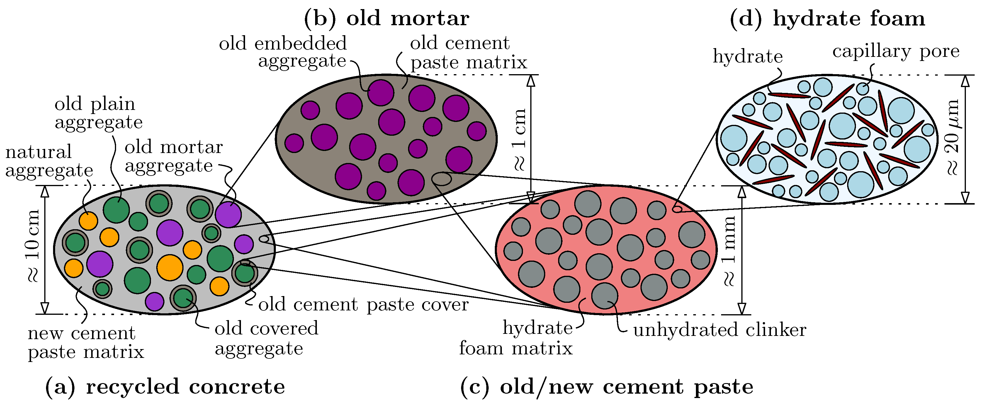
Figure 2.
Visual classification of typical coarse recycled aggregates (see Bendimerad et al. [32] for more details on the aggregates).
Figure 2.
Visual classification of typical coarse recycled aggregates (see Bendimerad et al. [32] for more details on the aggregates).

Figure 3.
Classification of recycled aggregates used in the study of Liu et al. [17]: cut recycled concrete sections before (a) and after (b) image processing, and their schematic classification (c). Reproduced with permission from Liu et al. [17], Elsevier, 2011.

Figure 4.
Schematic representation of ITZ-driven failure (cracking) in recycled concrete under uniaxial compressive loading in vertical direction.
Figure 4.
Schematic representation of ITZ-driven failure (cracking) in recycled concrete under uniaxial compressive loading in vertical direction.

Figure 5.
Definition of coordinate systems, position angle, and orientation angles: (a) Cartesian base frame as well as polar angle describing the position along the aggregate surface; (b) spherical base frame as well as azimuth angle and polar angle describing the orientation of the hydrate needle.
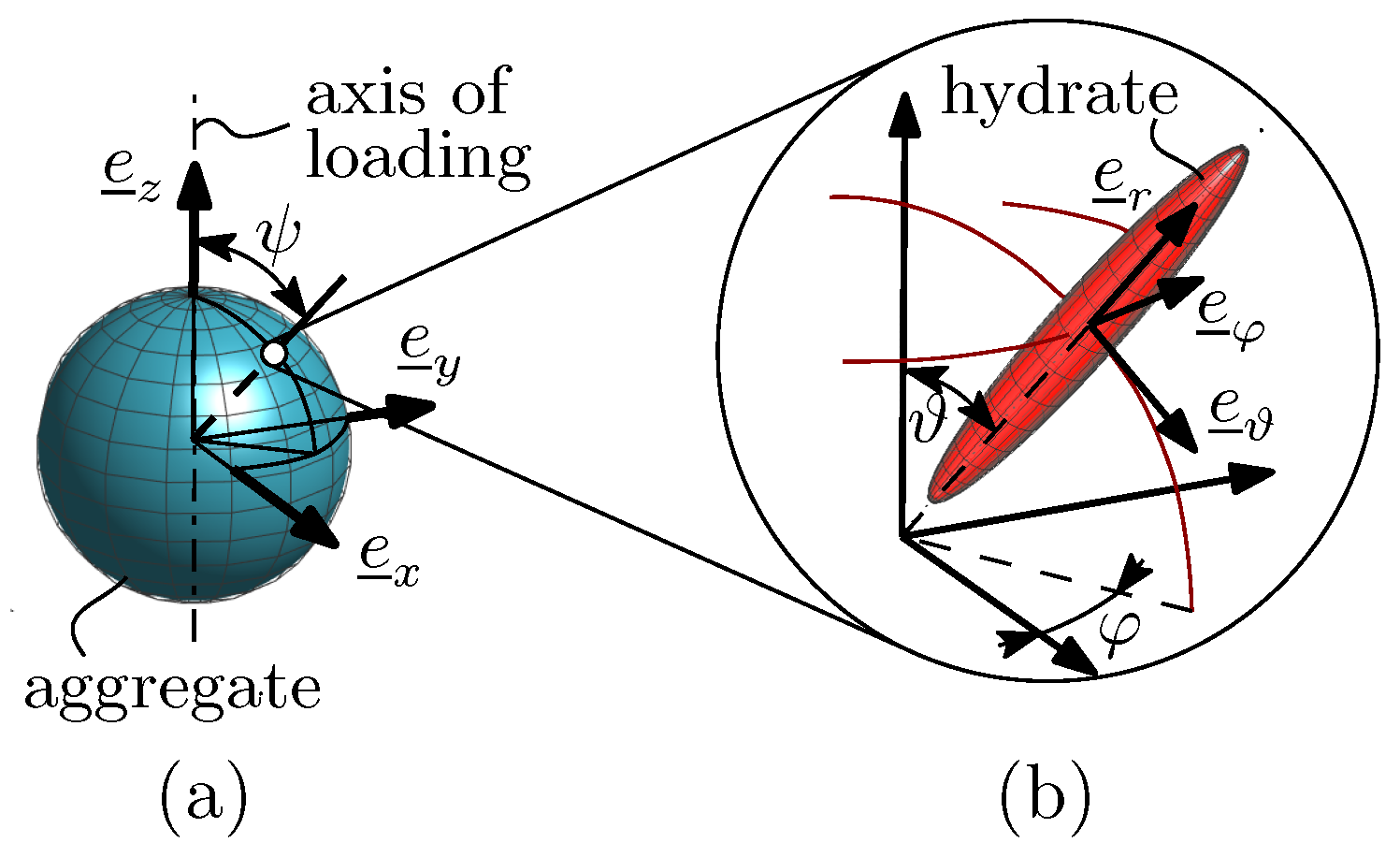
Figure 6.
Uniaxial compressive strength evolution with respect to the hydration degree of the new cement paste matrix : (a) for an old cement paste-related -ratio amounting to and different new cement paste-related -ratios, whereby solid lines refer to concrete containing recycled aggregates only () and dashed lines refer to conventional concretes without recycled aggregates (); (b) for different old and new cement paste-related -ratios and .
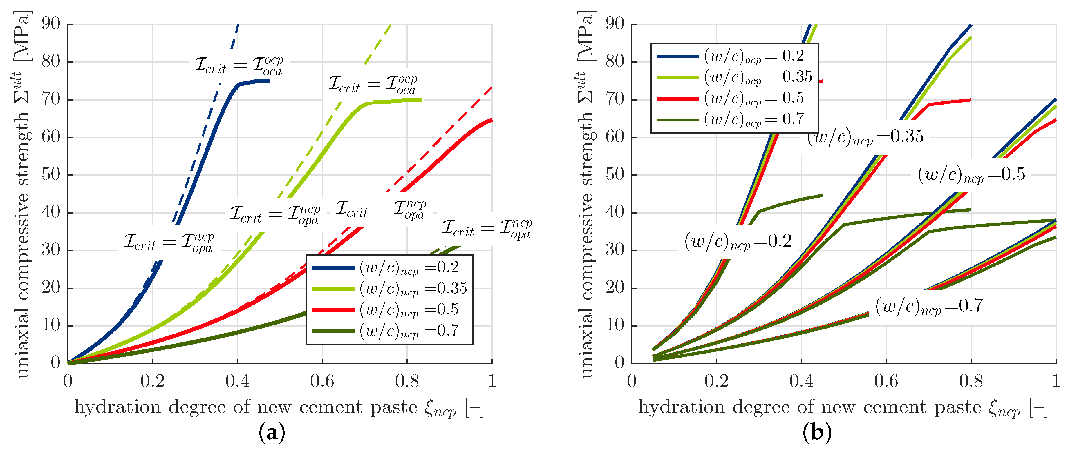
Figure 7.
Uniaxial compressive strength of the benchmark recycled concrete as function of the ITZ porosity factor for different hydration degrees: (a) for , and (b) for . The solid lines represent the material strength, and the dashed lines represent the theoretical strength in case of -failure only.
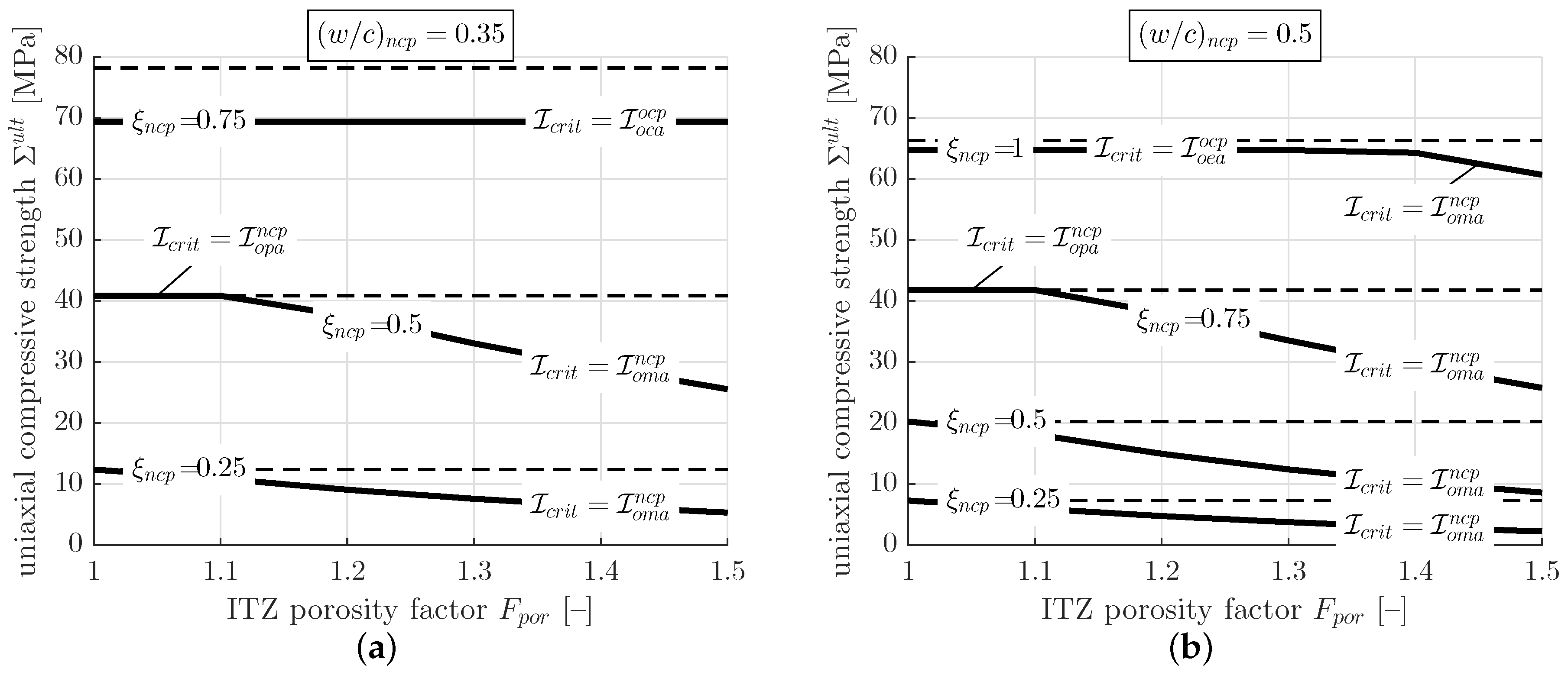
Figure 8.
Uniaxial compressive strength evolution of the benchmark recycled concrete for (a) one dominating recycled aggregate morphology and (b) for the three limit cases of recycled aggregate morphology, and for different new cement paste-related -ratios.
Figure 8.
Uniaxial compressive strength evolution of the benchmark recycled concrete for (a) one dominating recycled aggregate morphology and (b) for the three limit cases of recycled aggregate morphology, and for different new cement paste-related -ratios.
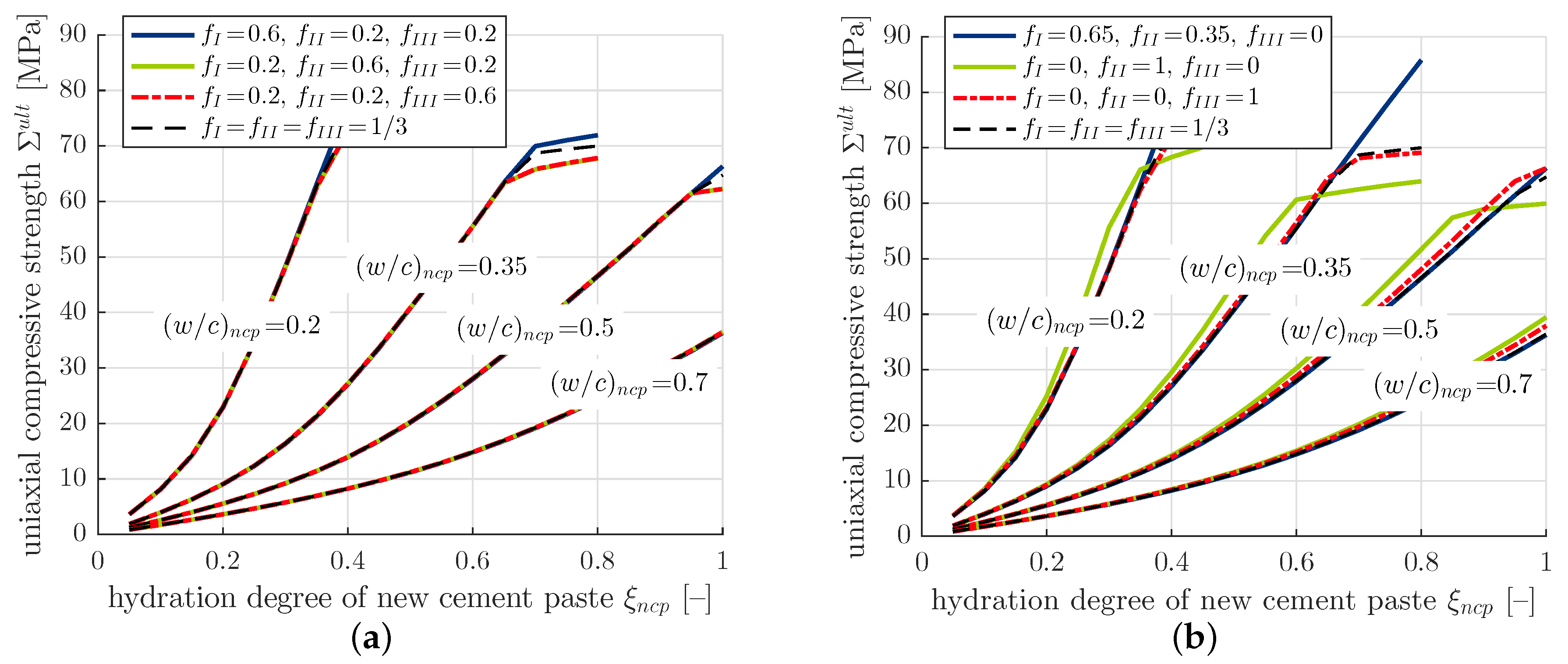
Figure 9.
Dimensionless uniaxial compressive strength of recycled concrete (normalized with respect to the strength of the benchmark composition with ) as function of the recycled aggregate-related old cement paste volume fraction: (a) for , and (b) for .
Figure 9.
Dimensionless uniaxial compressive strength of recycled concrete (normalized with respect to the strength of the benchmark composition with ) as function of the recycled aggregate-related old cement paste volume fraction: (a) for , and (b) for .

Figure 10.
Dimensionless uniaxial compressive strength of recycled concrete (normalized with respect to the strength of conventional with ) as function of the recycled aggregate-related old cement paste volume fraction: (a) for , and (b) for .
Figure 10.
Dimensionless uniaxial compressive strength of recycled concrete (normalized with respect to the strength of conventional with ) as function of the recycled aggregate-related old cement paste volume fraction: (a) for , and (b) for .
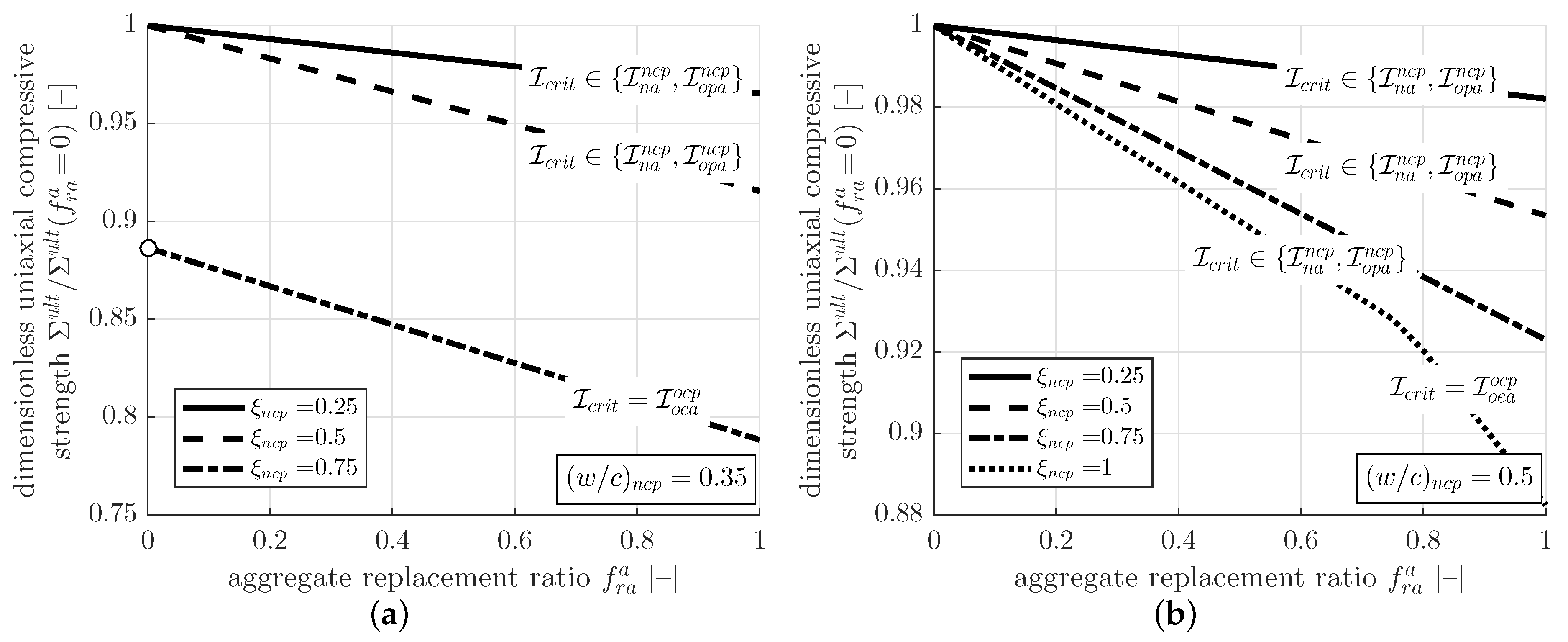

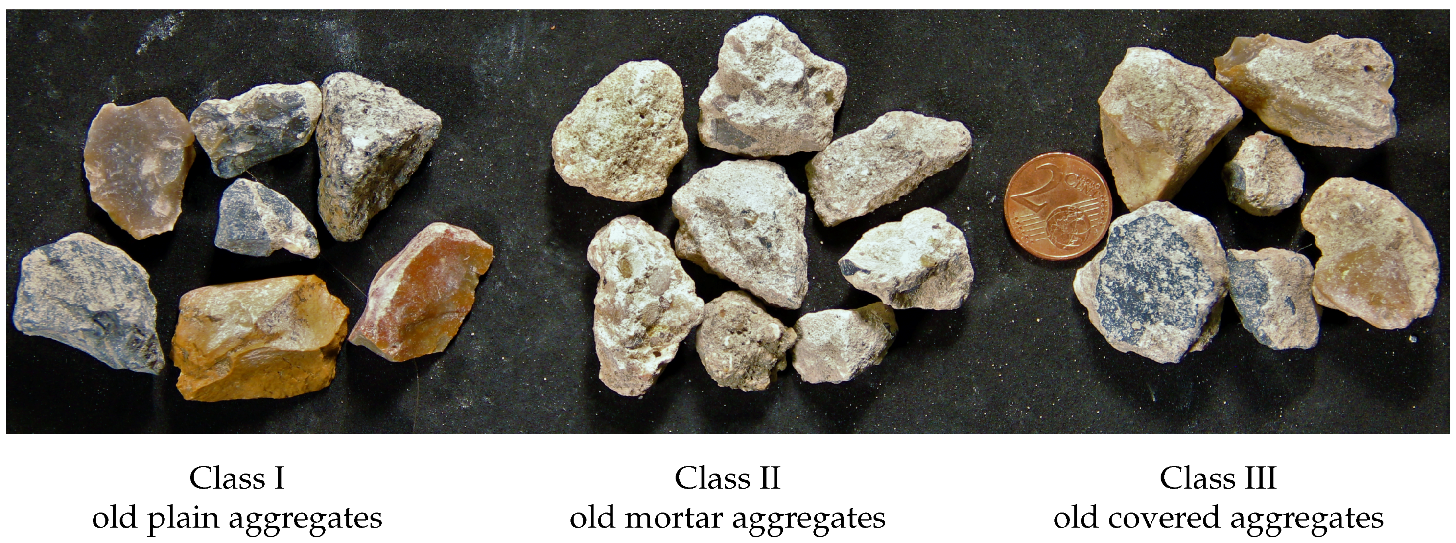
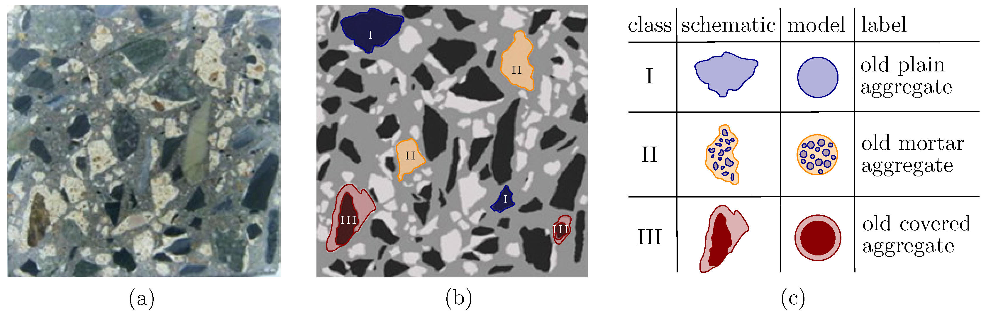
Table 1.
Non-zero isotropic elasticity constants of material phases according to [21].
Table 1.
Non-zero isotropic elasticity constants of material phases according to [21].
| Bulk Modulus | Shear Modulus | |||
|---|---|---|---|---|
| k [GPa] | [GPa] | |||
| clinker | 116.58 | 53.81 | ||
| hydrates | 18.69 | 11.76 | ||
| aggregates (old and new) | 35.35 | 29.91 | ||
| hydrates | 0.00 | 0.00 | ||
© 2018 by the authors. Licensee MDPI, Basel, Switzerland. This article is an open access article distributed under the terms and conditions of the Creative Commons Attribution (CC BY) license (http://creativecommons.org/licenses/by/4.0/).
Share and Cite
MDPI and ACS Style
Königsberger, M.; Staquet, S. Micromechanical Multiscale Modeling of ITZ-Driven Failure of Recycled Concrete: Effects of Composition and Maturity on the Material Strength. Appl. Sci. 2018, 8, 976. https://doi.org/10.3390/app8060976
AMA Style
Königsberger M, Staquet S. Micromechanical Multiscale Modeling of ITZ-Driven Failure of Recycled Concrete: Effects of Composition and Maturity on the Material Strength. Applied Sciences. 2018; 8(6):976. https://doi.org/10.3390/app8060976
Chicago/Turabian StyleKönigsberger, Markus, and Stéphanie Staquet. 2018. "Micromechanical Multiscale Modeling of ITZ-Driven Failure of Recycled Concrete: Effects of Composition and Maturity on the Material Strength" Applied Sciences 8, no. 6: 976. https://doi.org/10.3390/app8060976
Note that from the first issue of 2016, this journal uses article numbers instead of page numbers. See further details here.