Variable Pitch Approach for Performance Improving of Straight-Bladed VAWT at Rated Tip Speed Ratio
by
 , ,
, ,
Zhenzhou Zhao
1,* ,
,
Ruixin Wang
1,
Wenzhong Shen
2,
Tongguang Wang
3,
Bofeng Xu
1,
Yuan Zheng
1 and
Siyue Qian
1 1
College of Energy and Electrical Engineering, Hohai University, Nanjing 210098, Jiangsu, China
2
Department of Wind Energy, Technical University of Denmark, 2800 Lyngby, Denmark
3
Jiangsu Key Laboratory of Hi-Tech Research for Wind Turbine Design, Nanjing University of Aeronautics & Astronautics, Nanjing 210016, Jiangsu, China
*
Author to whom correspondence should be addressed.
Appl. Sci. 2018, 8(6), 957; https://doi.org/10.3390/app8060957
Submission received: 2 May 2018
/
Revised: 26 May 2018
/
Accepted: 5 June 2018
/
Published: 11 June 2018
(This article belongs to the Special Issue Wind Turbine Aerodynamics)
Abstract
:Featured Application
This research provides a new pitching approach to increase the maximum power efficiency of vertical axis type wind turbines and water turbines used to absorb marine current energy. This approach did not deny the validity of the traditional methods. On the contrary, the new approach combined with traditional pitching method will improve power efficiency at all tip speed ratios, and well solve the problems of low efficiency and poor self-starting ability of the turbines.
Abstract
This paper presents a new variable pitch (VP) approach to increase the peak power coefficient of the straight-bladed vertical-axis wind turbine (VAWT), by widening the azimuthal angle band of the blade with the highest aerodynamic torque, instead of increasing the highest torque. The new VP-approach provides a curve of pitch angle designed for the blade operating at the rated tip speed ratio (TSR) corresponding to the peak power coefficient of the fixed pitch (FP)-VAWT. The effects of the new approach are exploited by using the double multiple stream tubes (DMST) model and Prandtl’s mathematics to evaluate the blade tip loss. The research describes the effects from six aspects, including the lift, drag, angle of attack (AoA), resultant velocity, torque, and power output, through a comparison between VP-VAWTs and FP-VAWTs working at four TSRs: 4, 4.5, 5, and 5.5. Compared with the FP-blade, the VP-blade has a wider azimuthal zone with the maximum AoA, lift, drag, and torque in the upwind half-cycle, and yields the two new larger maximum values in the downwind half-cycle. The power distribution in the swept area of the turbine changes from an arched shape of the FP-VAWT into the rectangular shape of the VP-VAWT. The new VP-approach markedly widens the highest-performance zone of the blade in a revolution, and ultimately achieves an 18.9% growth of the peak power coefficient of the VAWT at the optimum TSR. Besides achieving this growth, the new pitching method will enhance the performance at TSRs that are higher than current optimal values, and an increase of torque is also generated.
1. Introduction
Wind turbines absorb wind energy and convert it into mechanical energy, and are classified according to the orientation of their axis of rotation into horizontal-axis wind turbines (HAWTs) and vertical-axis wind turbines (VAWTs). The HAWTs, represented by three-bladed propeller turbines, are the most common wind turbines because of the highest performance and easy manufacturing as a result of the great advance of aerodynamics and material engineering [1]. The VAWTs are further grouped into lift-type and drag-type. The lift-type VAWTs, which employ airfoil section blades to generate lift force as HAWTs, have higher rotation speed and better performance than the drag-type. The lift-type VAWTs, represented by the Φ-type and the straight-bladed type of Darrieus turbine, are also well-known [2]. On the other hand, most of them are used in small-scale applications, although they have several advantages over HAWTs, such as the ability to accept wind from any direction without yawing and the ability to provide direct rotary drive to a fixed load [3]. Some of the disadvantages of the VAWTs include an inability to self-start and relatively lower efficiency [4,5].
Darrieus turbine blades use airfoil sections designed as aircraft wing profiles. The NACA0012, NACA0015, and NACA0018 profiles are commonly used as blade sections [6]. Typically, these are designed to operate at small angles of attack (AoAs), lower than ±10°. At angles higher than this, the airfoil stalls and the flow separates on the upper surface of the blade, causing a loss of lift and an increase in drag [7]. At the startup of the turbine, a zero-tangential flow speed contributes to a large AoA, which then makes the airfoil stall. In this case, the pressure drag of the blade is so high that the lift cannot overcome the drag to self-start [8], not to mention any additional load from the electricity generator. Previous studies proposed a number of methods to make a self-starting lift-type VAWT. Kirke [9] reviewed those studies, and stated that high solidity turbines have the potential to increase the self-starting torque, but a higher solidity lowers the maximum power coefficient and narrows the operating range. Beri et al. [10] maintained that the Darrieus type VAWTs with asymmetrical blades have better self-starting behavior, but unfortunately, this also causes a reduction in peak efficiency. Zamani et al. [11,12] numerically investigated a 3-kW straight-bladed Darrieus type VAWT with a designed J-shaped profile. Their results showed that the J-shaped profile could suppress the vortices and improve the self-starting of the turbine. The hybrid wind turbine, comprising two vertical co-axial rotors, is normally constructed as a Darrieus with drag-type blades in the middle [13]. The primary purpose of the hybrid design is to promote the lack of torque when self-starting and at low tip speed ratios (TSRs) [4]. They can self-start normally, but after starting, they are less efficient than a turbine with normal lift due to the negative drag created at the middle [14]. It has been found that the above approaches hardly provide a way to promote both the self-starting ability and the peak power coefficient of the VAWTs at same time.
A particular method to address those issues is to develop a variable pitch (VP)-straight-bladed VAWT to control the pitch angles of the blades on each azimuthal angle in order to maximize turbine torque and start up easily [15]. A reduction of stall is the main mechanism whereby VP-technology produces significant improvement of the torque at start up and low TSRs [16]. Besides offering the greatest potential for achieving significantly increased torque at low and intermediate TSRs, VP-technology is also used to promote peak efficiency [17,18,19]. VP-VAWTs consist of active and passive-type turbines. The active designs are defined as those systems that produce blade pitch change through means other than the direct action of the aerodynamic forces acting on them in passive designs [16]. Staelens et al. [7] introduced three modifications for the increased power output of a straight-bladed VAWT by varying its pitch. The third modification proposed a continuous variation in the local AoA correction during the rotation cycle using a sinusoidal function. Although the power output obtained by using such a modification is less than the other two, it has the inherent advantage of being practically feasible. Also, Kiwata et al. [4] described a micro VP-VAWT that varies the pitch angle according to the azimuthal angle. The performance of the VP-VAWT was measured in an open-circuit wind tunnel, and the results were better than those of the fixed pitch (FP)-VAWT. Erickson et al. [20] tested the effects of cyclic blade pitch actuation on the efficiency and operability of a high-solidity VAWT with a cam and control rod mechanism to prescribe the pitch dynamics in the wind tunnel over a wide range of design and operational variables. The results revealed that a tuned first-order sinusoidal actuation system could achieve a maximum absolute power coefficient of 0.436, which is an increase of 35% over the optimal fixed-blade configuration, with self-starting capabilities and drastically improved performance at a wide range of suboptimal operating conditions. Hwang et al. [21] investigated the performance of a VP-turbine controlled by a cycloidal strategy. Compared with the FP-turbine, the performance at the upwind half-cycle of the VAWT with the optimized blade pitch angle was greatly improved, particularly at the azimuth region from 90° to 180°; the effective region was expanded, and was nearly twice as large as that of the FP-case. Chougule et al. [17] designed a 500-W VAWT to implement the pitch control mechanism using the cyclic VP-technology. Its aerodynamics were predicted using the double multiple stream tube (DMST) model, and their results showed that only a 5° increase of the pitch angle amplitude increased the power coefficient of the VAWT by 12%.
Despite the improvement of the self-starting ability and power coefficient, the above VP-approaches have the same limitation, which is mainly about the performance enhancement of azimuths with high AoAs in the case of the FP. In FP-VAWTs, each blade is constantly subjected to a variation of the AoA. Since the AoA constantly changes, the blade will generate large torque in some azimuthal angles, and low torque in other azimuthal angles. The overall performance is determined by the average torque of the blade in a cycle path line. Evidently, the low torques will produce a lower average value, and then degrade the power efficiency. The azimuthal position with the biggest geometric AoA in FP-VAWTs will achieve the biggest increase in the performance of the blade in VP-VAWTs. Assuming that the biggest geometric AoA is close to and below the stall value at the rated TSR, the magnitude of the maximum increase of the AoA would be much smaller if it still used the above-mentioned VP-approaches; thus, the increase of the AoA in other azimuths and the peak efficiency of the turbine would be much smaller, too.
To change this, we proposed a new VP-approach that was intended to mainly promote the performance of the blade working in the azimuths with smaller AoAs in FP-VAWTs. Ultimately, the aim is to largely enhance the peak efficiency of the VAWT in the rated or larger TSR. In this paper, the effect of the new approach on the performance of the blade or the turbine are investigated using a method implementing the double multiple stream tube (DMST) model.
2. Explanation of Variable Pitch Concept
2.1. Oscillating AoA
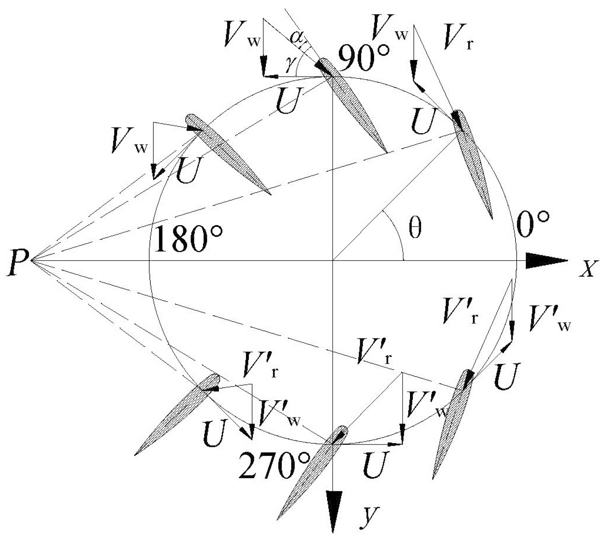
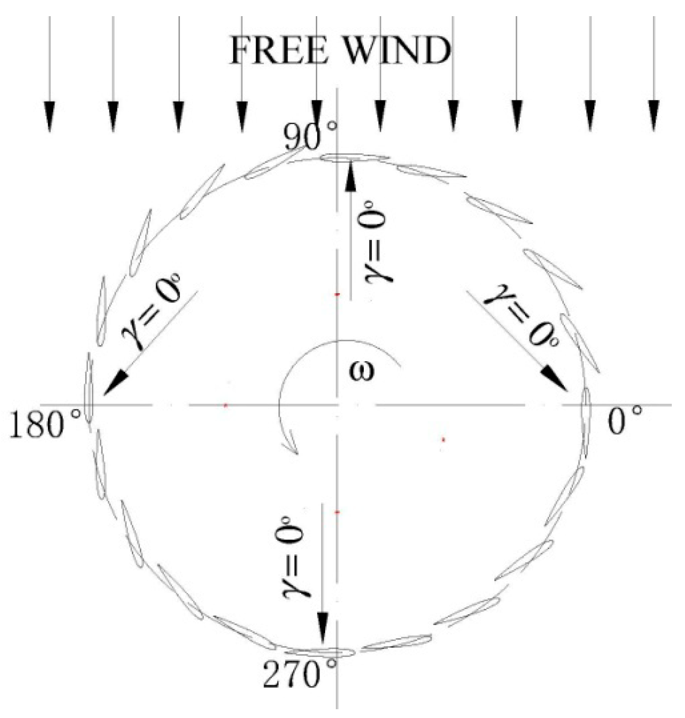
The Darrieus-type VAWT is a cross-flow rotor whose axis of rotation meets the flow of the working fluid at right angles. The blades perform the work twice in one cycle: i.e., the upwind half-cycle (azimuthal angle from 0° to 180°, where the 0°, 90°, 180°, and 270° positions are defined in Figure 1) and the downwind half-cycle (ranging from 180° to 360°). The azimuth angle of 0° is defined as a position where the directions of the local wind speed ‘Vw’ and the tangential flow speed ‘U = rϖ’ are the same; the azimuthal angle of 180° is the position where the directions of the two speeds are opposite; as its anticlockwise rotation, the azimuthal angle of 90° is the position moving anticlockwise on a quarter circle from 0°, which is the fixed reference position. The resultant flow, which is the vector sum of the local wind speed ‘Vw’ and the tangential flow speed ‘U = ϖr’, always comes from the upwind side of the blade: i.e., the outer side on the upwind half-cycle and the inner side on the downwind half-cycle [22]. Accordingly, as illustrated in Figure 1, the rotating blade experiences a changing resultant flow, including its magnitude and direction. The changing direction of the resultant velocity and chord line of the airfoil causes the oscillating AoA between the negative and positive values following a sinusoidal function of the azimuthal angle.
As shown in Figure 2, the AoA is determined by:
where is the AoA, a is the axial induction factor defined as a = V/Vw (V is the velocity of the flow in the stream tube, Vw is the velocity of the free wind), θ is the azimuthal angle, and represents the local TSR, where ω is the rotational speed, R is the rotational radius. The 0° and 180° positions are transformation points of the AoA between the negative and positive values, which determine their zero AoAs. Affected by the oscillating AoA, the blade of the VAWT inevitably produces fluctuating torque, even in steady conditions. For a given airfoil section, the non-dimensional normal and tangential forces are written as:
where and are the normal force and tangential force coefficients, respectively, and and are the lift and drag coefficients, respectively. According to Equations (2) and (3), the blade in the 0° and 180° azimuths will generate a zero-normal force and a negative tangential force, which cause a negative torque, according to Equation (4):
where M presents the torque of the blade, ρ is the air density, c is the chord length, 2H is the height of the blade, Vr is the local resultant velocity, and R is the rotation diameter. Due to the continuity of the blade torque variation, produced by the 0° and 180° azimuths, the torque in a zone around the 0° or 180° azimuth remains negative, and a wider zone may have a positive torque, but is still not big enough. In contrast, the 0° and 180°, and 90° and 270° angles produce the maximum AoAs. This is because the directions of the upwind flow and tangential flow are vertical to each other (Figure 1), and furthermore, the 90° azimuth having the larger upwind flow speed normally shows better aerodynamics than the 270° azimuth.
2.2. Aerodynamics in Traditional VP-Technology
The VAWT blade is subject to cyclic variations in wind speed and the AoA, which are efficiency improvements that can result from corresponding variations of the pitch angle of the blade to optimize the AoA at each point in its cycle [20]. Any improvement made to the AoA can be of a cyclic nature, as shown in Figure 3 [23]. Thus, a typical curve of the pitch angle in traditional VP-technology is expressed by Equations (5) and (6):
where is the variable value of the pitch angle changed with the azimuth, is the maximum pitch angle at a certain TSR, is the maximum pitch angle at all of the TSRs, is the TSR, is the TSR of max at zero , and θ is the azimuthal angle.
In another conventional VP-technology of VAWT, the blades have an oscillatory motion around their own axis, which was superimposed on the uniform rotation motion. Considering a cross-section of the turbine, the lines normal to the profile chord for every blade position intersect a given point “P” during a complete revolution (Figure 4) [24]. The variation of the pitch angle with respect to the azimuthal angle is expressed as:
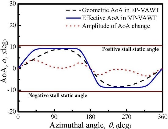
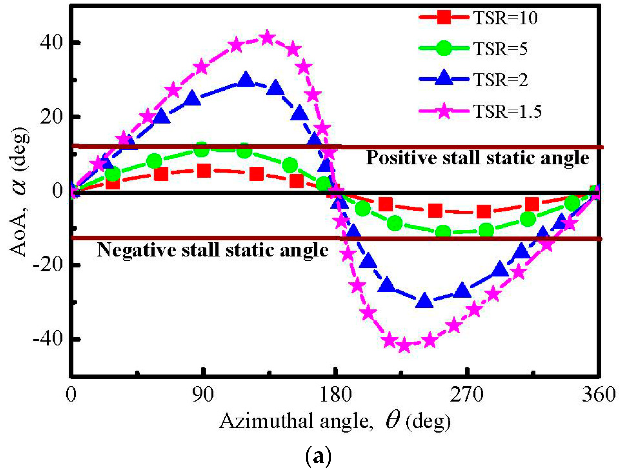
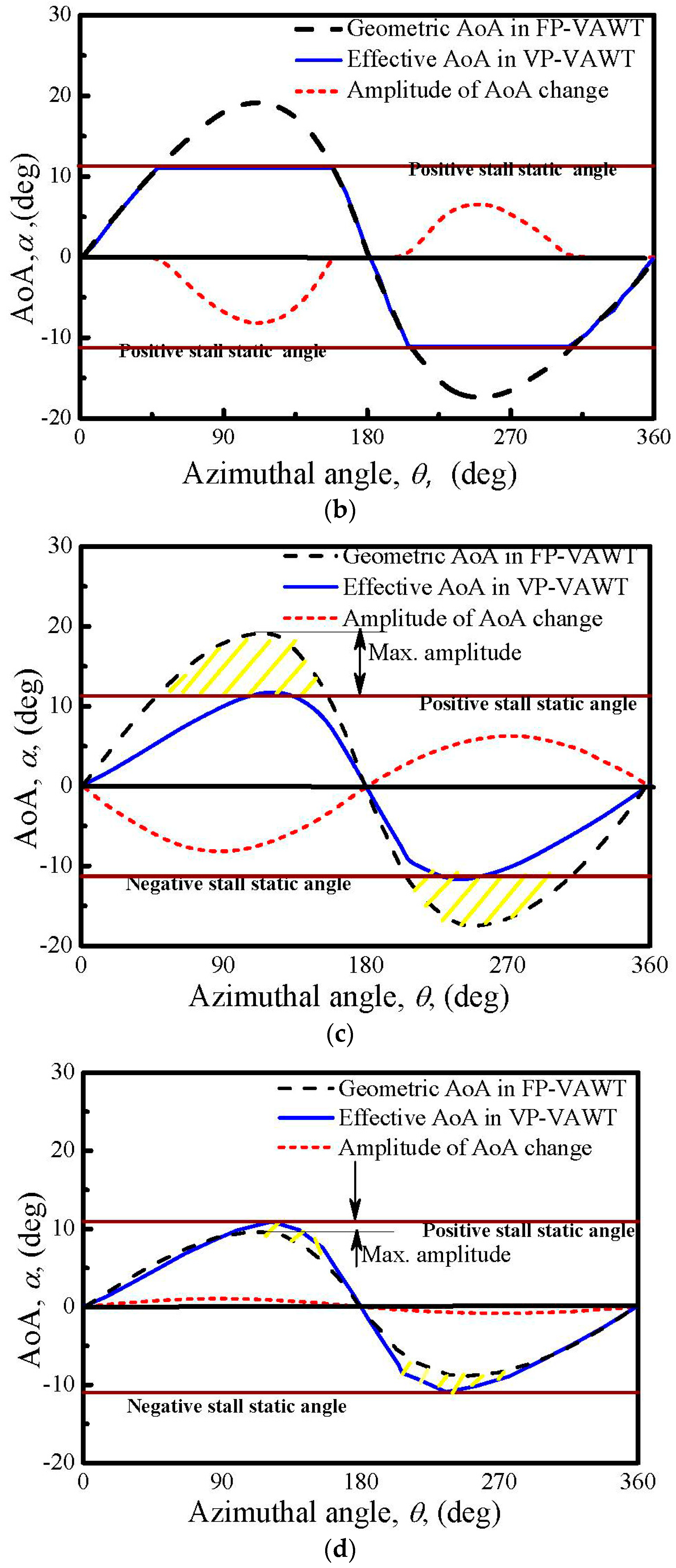
Two conventional VP-approaches have one point in common: the azimuthal angle with a larger geometric AoA will be given a larger pitch angle. Affected by the performance, as expressed by the lift coefficient () of the airfoil, the blade has a stall static AoA of about 10°, as shown in Figure 5a [18]. At the start-up and small TSRs, the maximum AoA is much greater than the stall angle, the lift of the blade will decrease, and the drag will greatly increase after the stall occurs. In such cases, the VP-technology will change the pitch angle in the direction of the decreased AoA to avoid the stall. Two methods were used to achieve this goal. In the first method, the pitch angle changes only in the positions where the local geometric AoA exceeds the stall value, and the final local effective AoA is kept below the static stall angle [7,25], as illustrated in Figure 5b. The advantage of this method is that it makes the blade rotate with the optimum AoA in a much wider azimuthal zone. Its disadvantage is that the change of the pitch angle (represented by a dotted line in Figure 5b) is discontinuous at some points, which may not be practical to implement, and also causes early fatigue due to the abrupt dynamical loads [7]. The other method continuously changes the pitch angle following a sinusoidal function (Figure 5c). Under this control, the maximum amplitude of the sinusoidal function for the pitch angle is set to be equal to the maximum difference between the geometric AoA in the FP-VAWT and the effective AoA in the VP-VAWT. The advantage of this method is that the pitch angle as well as the forces changes smoothly and continuously, and then the method is physically and mechanically feasible to implement; the implementation procedures are presented in Figure 2 and Figure 3. However, the power efficiency, although significantly larger than that of the FP-VAWT, is much lower than that of the other method illustrated in Figure 5b, because the final local effective AoA curve also follows a sinusoidal function in which the blade experiences the maximum performance only at two inflection points. At an optimum or larger TSR, the pitch angle should change toward the direction of the increased AoA for an improved performance in terms of the increased peak power coefficient of the VAWT. Meanwhile, if the variation of the pitch angle follows a sinusoidal function, as shown in Figure 5d, the space for performance enhancement would be exceedingly limited, because the maximum amplitude of the AoA change is much smaller (Figure 5d). A new approach is explored next to solve this problem.
At an optimum or larger TSR, the pitch angle should change in the direction of the increased AoA for an improved performance in terms of the increased peak power coefficient of the VAWT. Alternatively, if the variation of the pitch angle follows a sinusoidal function, as shown in Figure 5d, the space for performance enhancement would be exceedingly limited, because the maximum amplitude of the AoA change is much smaller (Figure 5d). A new approach is explored next to solve this problem.
2.3. New VP-Approach
The new VP-strategy proposed in this paper focuses mainly on improving the performance by widening the range of the largest local effective AoA, instead of enlarging the maximum value. In the new VP-approach, the local effective AoA is kept below the stall angle and maintains a constant value in a wide zone during a rotation cycle; the curve is shown as a solid line in Figure 6. During the design of the new approach, four key points are adequately considered.
- (1)
- How to deal with the zero AoA at the azimuthal angles of 0° and 180°: Since the positions of the 0° and 180° angles are the transformation points between the positive and negative AoAs, the design of the new VP-approach cannot avoid the zero value AoAs. The pitch angles in these two positions remain at the zero value.
- (2)
- How to set the value of the constant effective AoA in Figure 6: At the rated TSR, the largest local AoA in a cycle should be designed as the optimum AoA corresponding to the largest lift–drag ratio, rather than the static stall AoA. Thus, if the pitch curve of the new approach is designed for a blade operating at the rated TSR, the constant value in Figure 6 should be equal to the maximum geometric AoA in a FP-VAWT, since both a larger and a smaller value would contribute to a smaller torque. Consequently, the pitch angles are also kept at zero at the two inflection-point locations, namely the azimuthal angles of 90° and 270°.
- (3)
- Is the approach physically and mechanically feasible to implement? The amplitude of the change of the pitch angle is shown in Figure 6 as a dotted curve. In this curve, the pitch angle changes smoothly and continuously, and eliminates the drawback of the design in Figure 5b. The whole variation process of the pitch is illustrated in Figure 7, which is easily accomplished mechanically, such as a specially designed cam. As shown in Figure 7, the pitch angles varies in each ¼ circle (0°–90°, 90°–180°, 180°–270°, and 270°–360°), and returns to zero at four positions (0°, 90°, 180°, and 270°). Here, we defined the presence of a positive pitch angle when the blade rotates counterclockwise around its own axis, and the leading edge of the blade points toward the inner side of the circular path. In contrast, the angle is negative when the blade rotates and the leading edge points in the opposite direction.
- (4)
- What is the effect of the new VP-approach on the performance of the blade? After the mechanical feasibility of the approach is validated in theory, the following study focuses on the investigation of the effect of the new VP-approach using the DMST model.
3. Computational Model
3.1. Geometric Characteristics of VATW
The geometric characteristics of the straight-bladed VAWT studied in this paper are as follows. The NACA0012 blade profile: a height of 2 m (H = 1 m, Figure 8), a rotation radius (R) of 1 m, a chord length of the blade of 0.09 m, with two blades. Two straight-bladed VAWTs are also referred to as H-type VAWTs, since their configurations are much like an “H” shape. The operating conditions of the H-type VAWT aerodynamic parameter chosen for this study are as follows: an air density of 1.225 kg/m3, a wind speed of 9 m/s, a kinematic viscosity of 1.48 × 10⁻⁵ m2/s. The curve of the pitch angle with respect to the azimuthal angle was designed with the condition of a TSR = 4.5, in which the FP-turbine generates the peak power coefficient. The performance at four TSRs values (i.e., TSR = 4, 4.5, 5.0, and 5.5) was predicted, and their results were compared with each other. In addition, as shown in Figure 8, the effect of the radial arm was not considered, even though it is also a source of drag that reduces the power performance, due to the use of the DMST algorithm in the subsequent research.
3.2. Aerodynamic Model of Double Multi Stream Tube (DMST) Model
The DMST model makes use of the blade element momentum (BEM) theory, whereby the performance of the rotor is calculated by coupling the momentum equation in the mainstream direction of the wind and the aerodynamics analysis of the interactions between the airfoils in motion and the oncoming flow on the rotor [15,26]. The first approach using a momentum model to analyze the flow field around a VAWT was developed by Templin [27], who considered the rotor as an actuator disk enclosed in a simple stream tube, where the induced velocity through the swept volume of the turbine was assumed to be constant. An extension of this method to the multiple stream tubes model was developed by Strickland [28], who considered the swept volume of the turbine as a series of adjacent stream tubes. Additionally, Paraschivoiu [29] developed an analytical model, the DMST model, which considers a multiple-stream tube system divided into two parts, where the upwind and downwind components of the induced velocities at each level of the rotor are calculated by using the principle of two actuator disks in tandem. Subsequently, many predicted the performance of the Darrieus turbine using the DMST model, and all of the results showed that the DMST model has a high prediction accuracy for predicting the aerodynamics of the lift-type VAWTs [24,30,31,32,33]. The Darrieus-type wind turbine at low TSRs normally experiences a large variation within its AoA, and the blades are dominated by dynamic stall. In such conditions, the prediction must consider the effect of the dynamic stall on the accuracy. However, in the paper, the detailed investigation is performed at a high TSR, which is higher than four. Meanwhile, the variation of the AoA is getting much smaller and no stall is occurring; thus it has little effect on the prediction accuracy [22]. Accordingly, the dynamic stall was neglected in the paper. The model relies on pre-existing lift and drag data to calculate the blade aerodynamics. In a cross-flow wind turbine, blade–vortex interactions may occur, but its effects are not clear. There is not a well-developed algorithm for the modification of the lift and drag data due to the impingement of the vortex on the blades [34]. Thus, the interaction was also neglected in our work.
Since this investigation is focused on an H-type VAWT, a simplified version of the DMST model applicable to a straight-bladed rotor is briefly outlined below [35,36,37]. For an H-type VAWT, the resultant velocity, Vr, during the upwind half-cycle can be determined from the velocity vector triangle shown in Figure 2, which then gives:
Applying the blade element theory and equating the change in momentum to the drag on the rotor for each stream tube, it is found that:
where is the dimensionless parameter of the radius, and is the unwind function that characterizes the upstream half-cycle of the rotor on the blade element rotating in this zone. The upwind function is given by the following equation:
where N is the number of the blades, and CN and CT can be calculated from Equations (2) and (3), respectively. The lift and drag coefficients, CL and CD, respectively, are obtained by interpolating the known experimental data using both the local blade section Reynolds number and the local AoA. The local AoA can be calculated from Equation (1). Also, using Equation (8), is given as a function of the induced upwind velocity for each blade element in rotation.
3.3. Tip Loss Consideration
For a finite aspect ratio of the blade, tip loss is unavoidable. Thus, the effect of the blade tip loss was considered in the modeling to achieve an accurate performance prediction. The tip loss characterizes the tendency for trailing the vorticity from the blade tip, or from any other point where the circulation distribution changes, thereby reducing the blade’s effectiveness. Prandtl’s tip loss factor is commonly employed for VAWTs, and Soraghan et al. [30] described the mathematics in detail.
3.4. Computational Procedure
For a given H-Type rotor geometry and rotational speed , a value of the local TSR is chosen by assuming that the interference factor a is unity. Thus, and are evaluated as first approximations, and the airfoil CL and CD characteristics are interpolated from the test data reported by Sheldahl and Klimas [38]. Then, using Equation (7), the normal and tangential force coefficients of the blade section are estimated, while Equation (10) allows the upwind function to be evaluated. With the first value of f, Equation (9) is used to calculate another value for the interference factor, and the iterations continue until successive sets of a are reasonably close. Convergence will be achieved, as the error is less than 0.0001. Once the final value of the upwind zone ‘a’ has been calculated, the local relative velocity Vr is determined from Equation (7) and the local AoA from Equation (1). A similar procedure is repeated for the downwind half-cycle. Additionally, it should be noted that here, the upwind velocity is an equivalent velocity expressed as Ve = (2a − 1)Vw.
4. Results Analysis
Due to the consideration of the tip loss of the blade, the results distributed along the spanwise direction of the finite length blade are not constant; their distribution shows symmetric characteristics on both sides of the middle height, namely H = 0, as shown in Figure 8. However, the differences between any two heights, except the position that is closest to the tip of the blade, are small for a large aspect ratio. Thus, the data from H = 0 are chosen to be analyzed and compared in the following sections.
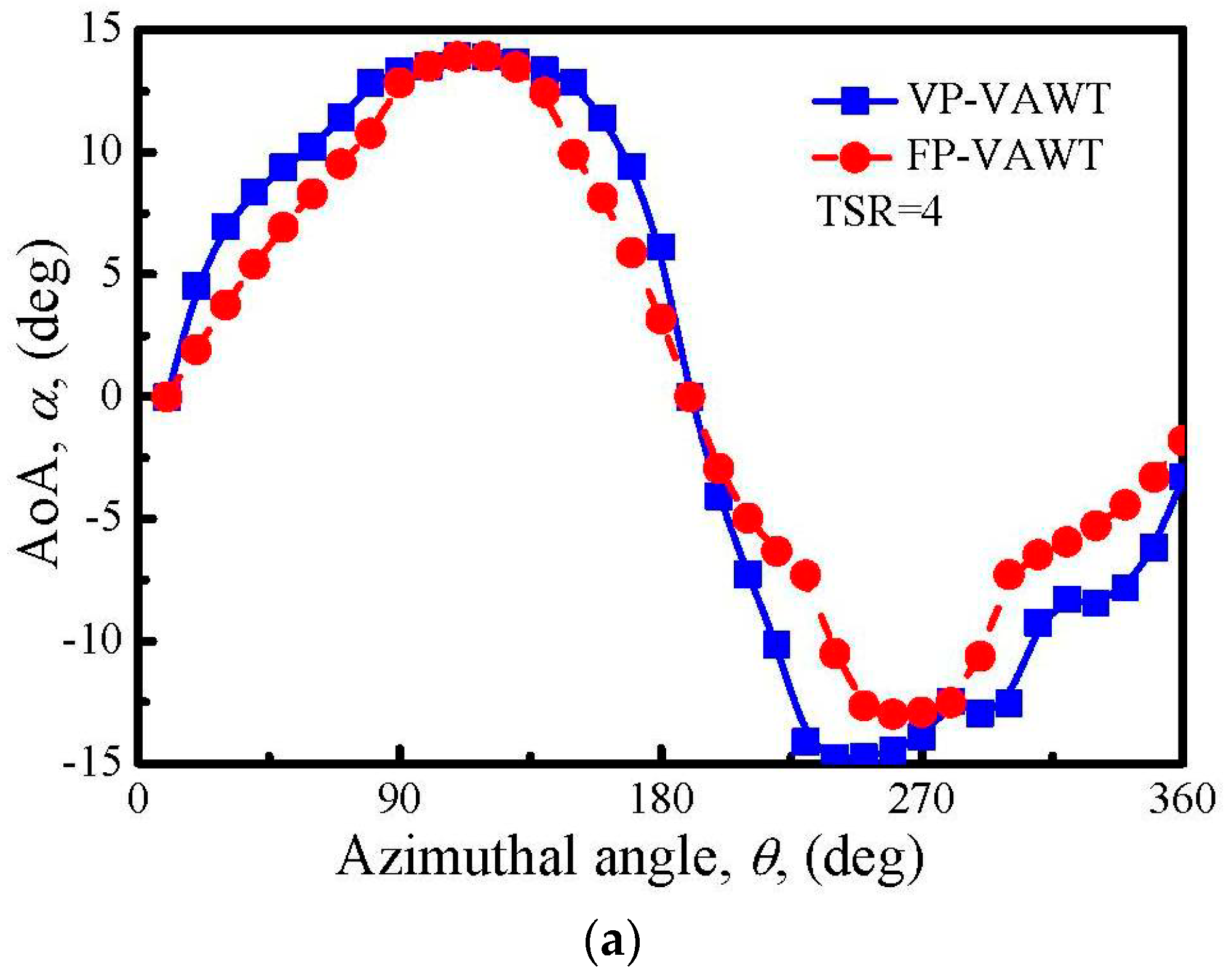
4.1. AoA Variation
The final variation of the AoA in a full cycle is shown in Figure 9. As required by the original specifications of the design, the new approach increases the AoA in most azimuthal angles, which is much obvious in the upwind region. The downward parabolic AoA curve with respect to the azimuthal angle is more open, and more azimuthal angles have a higher AoA, but the largest value is not changed in the upwind section. In the downwind region, the increase of the AoA is obvious when the TSR = 4, 4.5, and 5, but it decreases as the TSR increases, and even shows a negative tendency when the TSR = 5.5. As the rotation speed increases, more wind energy is absorbed into the stream tubes of the upwind part, and the steam flows though the stream tubes of the downwind part with lower velocity, which causes a lower AoA in the condition of a constant rotation speed. It is also observed in all of the sub-figurations that the real curve of the AoA is not as smooth as the designed one, especially in the downwind region. This is because the AoA strongly depends on the considerably changed axial induction factor.
4.2. Lift Force Variation
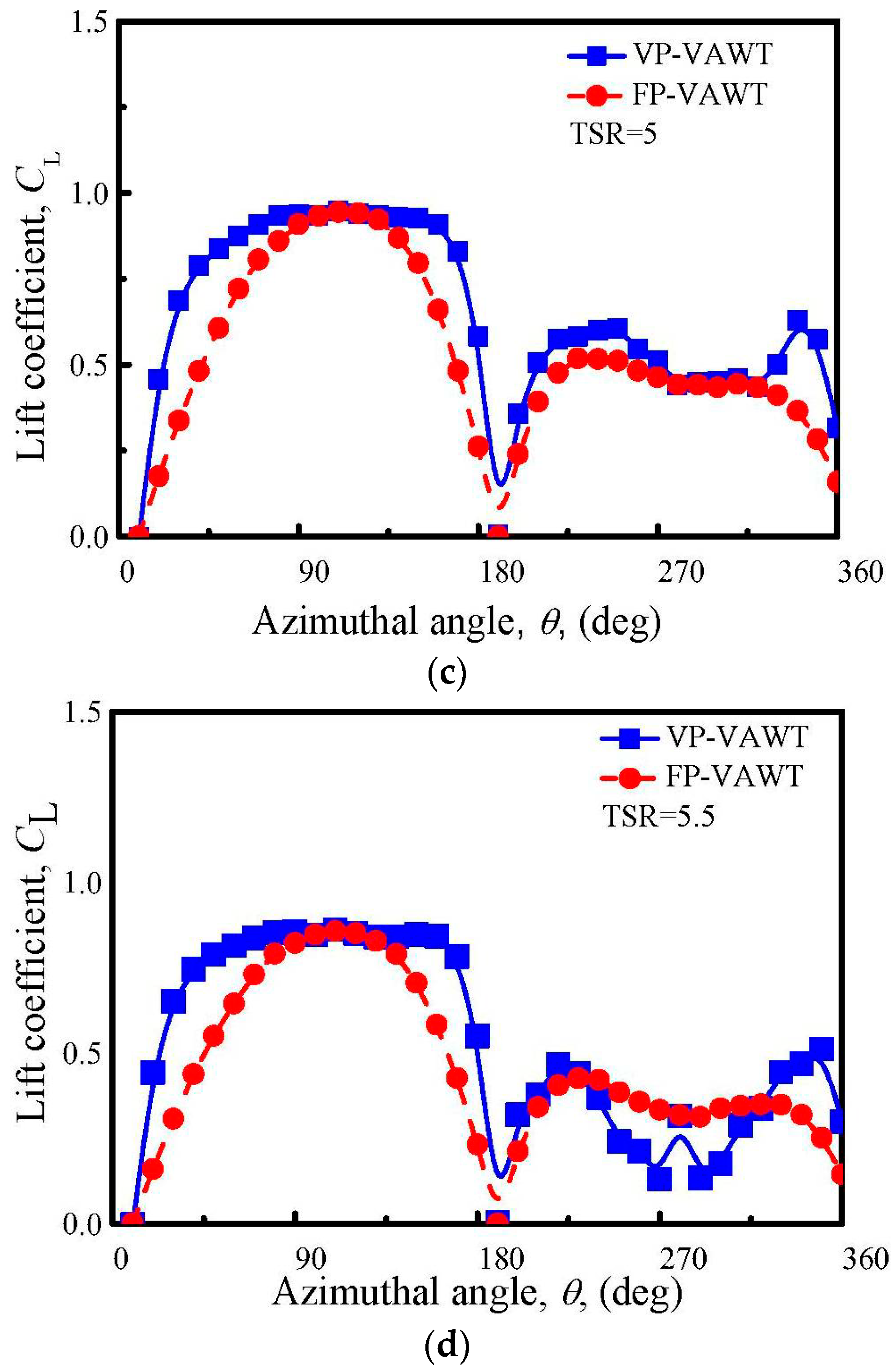
The lift generated by the blade is a key parameter of a lift-type VAWT, because it determines the magnitude of the tangential force that causes the turbine rotation. One of the effects of the new VP-control changes the lift of the blade. The variation of the local lift coefficient during a complete rotation in four TSRs is illustrated in Figure 10, which reveals that, when the TSR = 4, the lift coefficient fluctuates intensively during a whole range of azimuthal angles, whether in the VP-VAWT or FP-VAWT, and a much lower value is observed at around 90° and 270°. This is because the AoA values in the large region around 90° and 270° are still larger than the stall static angles, which leads to the occurrence of the stall and then a decreased lift coefficient. As can be observed in Figure 10, the VP-blade does not create a larger maximum lift coefficient than the FP-blade, but it does have a wider stall zone. The reason is that the new VP-approach increases the AoA and creates a wider azimuthal zone having a larger AoA than the stall value, but the maximum effective AoA is not changed. All of these phenomena indicate that the VP-approach designed for the rated TSR is not suitable to be applied to improve the performance of the VAWT at much lower TSRs.
At TSRs larger than 4.5, stall does not occur; the curve of the lift coefficient changes smoothly, and shows an arched shape in the upwind or downwind half-cycles in the FP-VAWT. In the same conditions, the stall does not occur in the VP-VAWT either; larger lift coefficients are obtained almost in the whole rotation zone except four at positions, namely: 0°, 90°, 180°, and 270°. Finally, the novel approach achieves a larger zone with the largest lift coefficients in the upwind half-cycle and two new larger maximum coefficients in the downwind half-cycle. A comparison of the increase among the TSRs reveals that the increase of the lift is in the downstream region as the TSR increases. Even when the TSR = 5.5, the lift is affected by the AoA; as shown in Figure 9, the VP-blade produces lower lift than the FP-blade in an extensive zone of the downwind region.
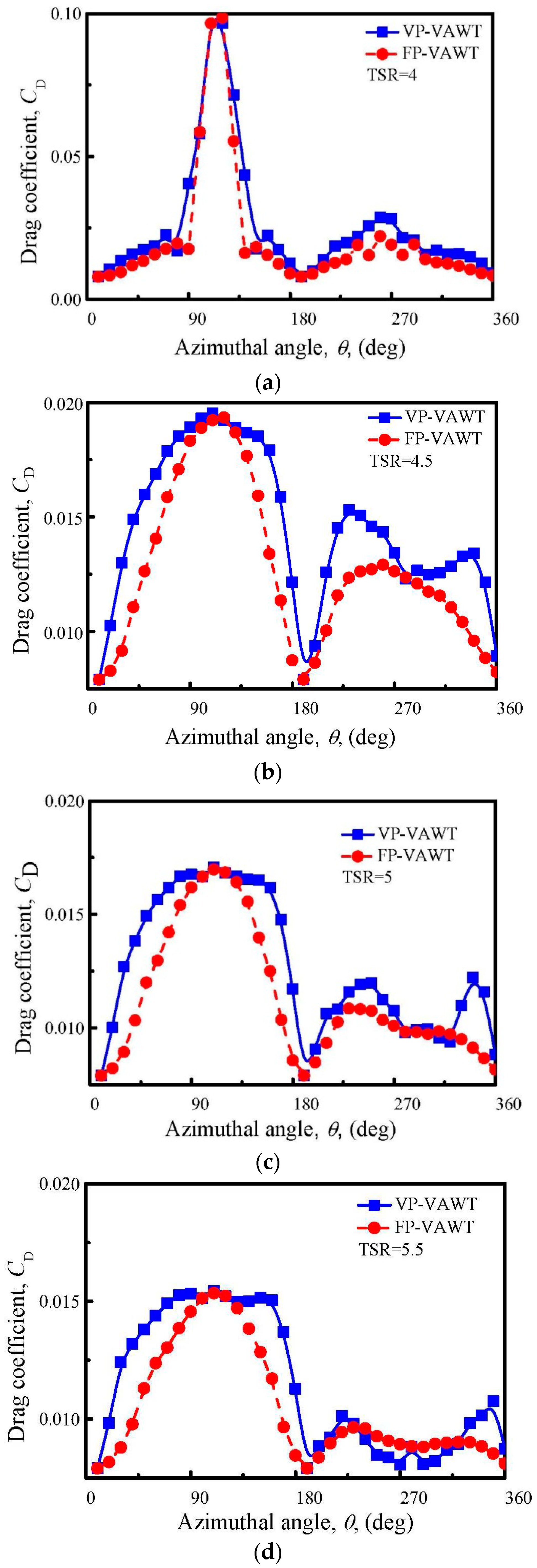
4.3. Drag Force Variation
The drag coefficients of the blades of the FP-VAWT and VP-VAWT are illustrated in Figure 11. First, when the TSR = 4, the blade that stalls generates a large peak drag in the upwind region, which is almost five times as large as that when the TSR = 4.5, and another larger peak drag in the downwind region of the VP-VAWT. A comparison of the distribution between the VP-VAWTs and FP-VAWTs indicates that the new VP control also increases the drag of the blade because of the increased AoA. The trends of the drag changes between the VP-VAWTs and FP-VAWTs are much like those of the lift changes. However, the increased drag cannot negate the advantage of the new VP-approach. According to the aerodynamics of the airfoil, the AoA that has the largest lift coefficient normally results in a large drag coefficient. The final effect is a promotion of the blade performance or not, which is determined by whether the component of the increase in the tangential direction of the lift is larger or smaller than that of the drag coefficient.
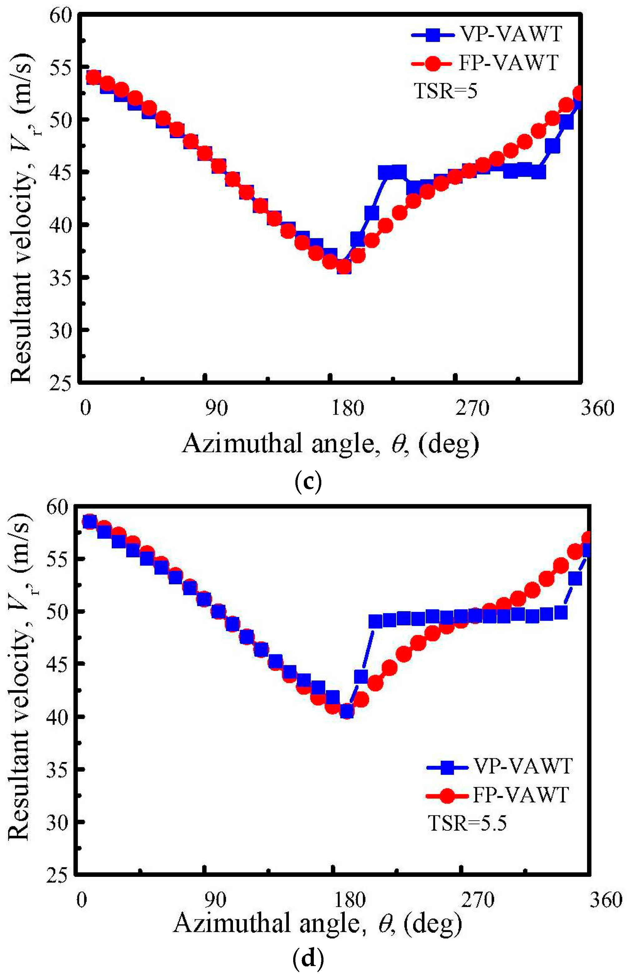
4.4. Resultant Velocity Variation
The resultant velocity, which is the vector sum of Vw and U, is depicted as a function of the azimuthal angle in Figure 12. Other than the free wind velocity, the resultant velocity is the effective flow velocity acting on the blade, which is another factor, together with the AoA, that determines the magnitude of all of the forces. The magnitude of the resultant velocity is determined by the tangential flow velocity and flow velocity going through the stream tube according to the local velocity triangle. At the same rotation speed as the VP-VAWT and FP-VAWT, in the upwind half-cycle, the pitch angle does not affect the local tangential flow velocity and wind velocity. This causes slight changes in the resultant velocity in the upwind half-cycle, as shown in Figure 12. The slight changes are also observed when the TSR = 4 and 4.5 in the downstream half-cycle, and large changes occur when the TSR = 5 and 5.5 (Figure 12). The VP-approach decreases the wake velocities of the upwind stream tubes, and changes the velocity of the stream flowing through the stream tubes and the axial induction factor of the downwind half-cycle. The changed stream velocity and axial induction factor determine the different resultant velocities. As depicted in Figure 12, when the TSR = 5.5, the resultant velocity has a tendency to be even in a wide zone of the downwind region.
4.5. Torque of Blade Variation
The torque of a single blade as a function of the azimuthal angle is shown in Figure 13, which reflects well the effects of the new VP-approach on the improvement of the aerodynamics of the blade in every azimuthal position. As expressed by Equations (3) and (4), the torque is extensively affected by lift and drag. For the increase of both forces, the final torque in the VP-VAWT significantly differs from that in the FP-VAWT. At a TSR = 4 and the downwind half-cycle, the torque is increased in some azimuthal angles, but it is also reduced in some zones; thus, it is not easy to directly judge whether the overall torque is increased or decreased (Figure 13). In comparison, when the TSR = 4.5, 5, and 5.5, a different extent of increase is obtained on both sides of the 90° azimuthal angle, where one peak torque is generated in the FP-VAWT, and then the low torque zone gets correspondingly narrower. In the downwind region, the large increase is shown when the TSR = 4.5 and 5; the VP-blade creates two new maximum values on the two sides of the azimuthal angle of 270°, where another peak torque of the FP-blade is generated. It should be noted that the former two new maximum values are larger than the latter ones; thus, the curve of the downwind section exhibits an “M” shape. At a TSR = 5.5, the torque is increased in some positions, and decreases in the zone adjacent to the 270° azimuthal angle.
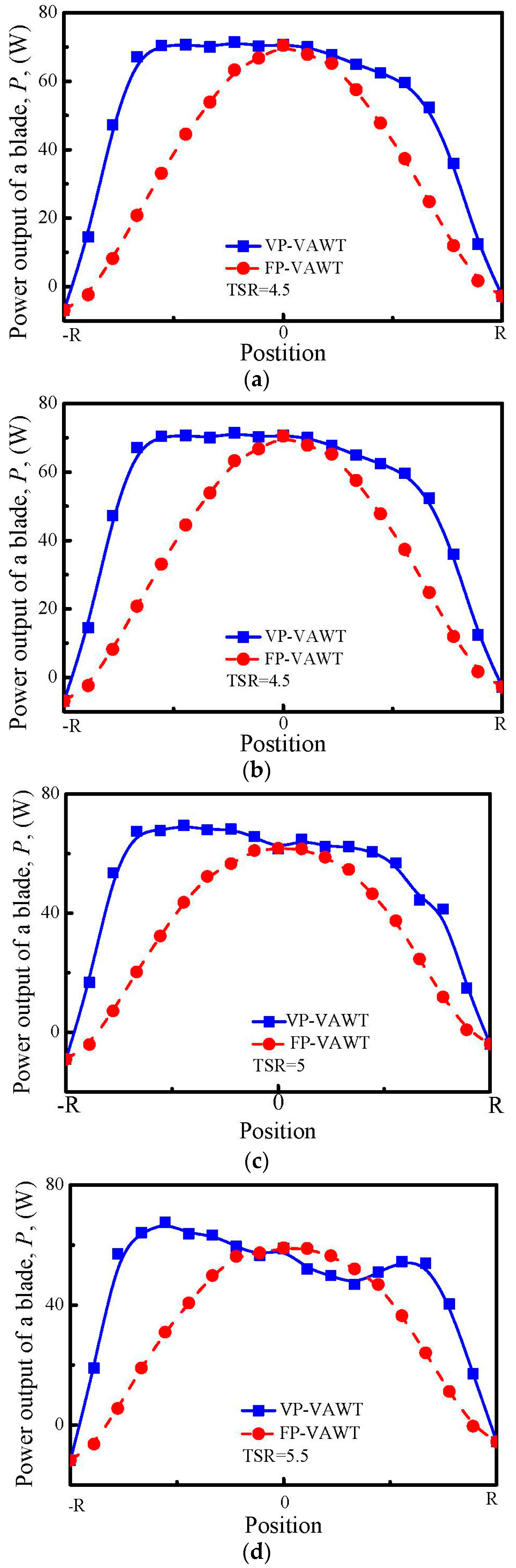
4.6. Power Output
The power output along the radial direction is presented in Figure 14; its value is equal to the sum of the power output of a stream tube in the upwind part and the corresponding downwind part, which can be written as Equation (11). Adding the power outputs of the stream tubes in all of the radial and heights positions, and subsequently dividing the power of the free wind, the total power coefficient is obtained through Equation (12):
where denotes the power coefficient; the subscript i is the radial position of the stream tube; up and dw represent the upwind and downwind region, respectively; t means total; and S is the swept area. As shown in Figure 14, the power output of the FP-blade shows the peak value in the radial position of r = 0; toward the two sides, the power is gradually reduced, and reaches zero or even a negative power in the −R or R positions. The whole curve of the FP-blade is a downward parabolic line. In comparison, the new VP-approach extends the position generated at the peak power from one point in the FP-VAWT to a wide radial zone. Therefore, the final distribution of the power output is similar to a trapezoid when the TSR = 4.5 and 5. For a TSR = 5.5, although a drop of the torque occurs downstream, as shown in Figure 13, the VP-blade still experiences an increase in the power output in most radial positions, because of a larger torque increase in the upwind region. The results presented in Figure 14 also show a small drop in the position of r = 0, but a larger increase occurs in other positions. Thus, the total power output will be absolutely increased.
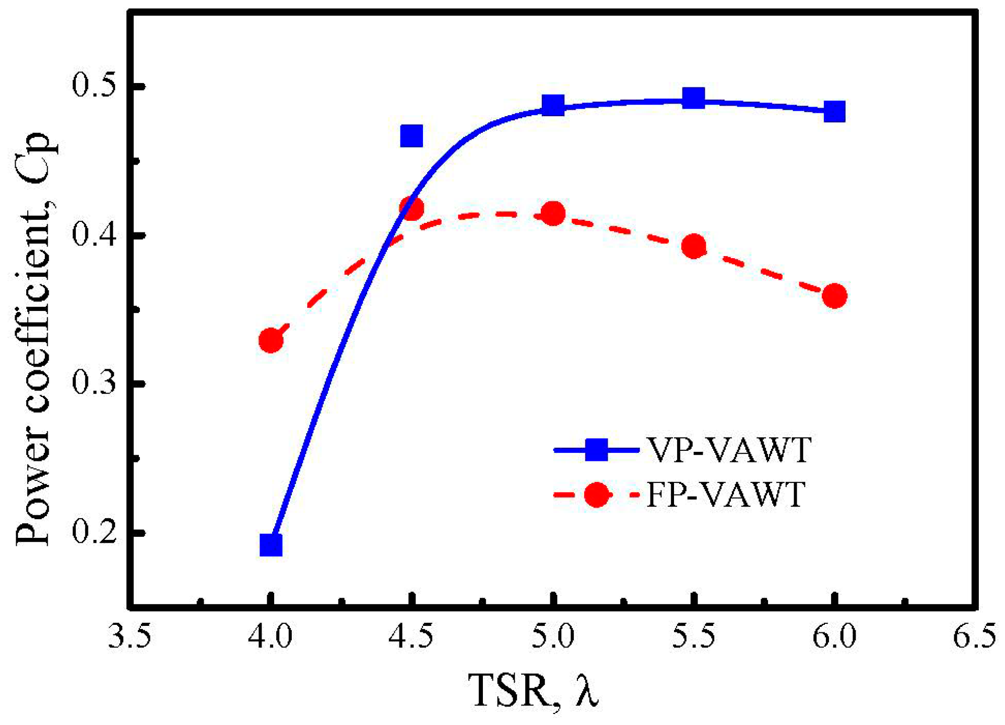
A comparison of the power coefficient of the two types of VAWTs when the TSR = 4 to 5.5 is shown in Figure 15, which reveals the obvious promotion of the power coefficient at a TSR = 4.5, 5, and 5.5. The increase is 16% at a TSR = 4.5, and becomes larger as the TSR increases. Finally, an 18.9% increase of the peak power efficiency of the VP-VAWT is achieved when the TSR = 5. The new curve has a wider TSR zone with a high power coefficient, and the drop in the power coefficient starts when the TSR = 5.5, but at a low rate. The results in Figure 15 clearly indicate that the new approach is highly suitable for improving the peak efficiency of the VAWT at the optimum or larger TSR.
Since the parasitic drag of the radial arm was not considered in the investigation, the prediction value may be higher than the real one in Figure 15. While the structure of the arm can be well-designed, such as using an airfoil profile and being installed at a zero AoA relative to the free wind, several methods such as this can greatly reduce their parasitic drag. Therefore, the new pitching approach does effectively promote the overall performance of the turbine, even after considering the parasitic drag of the arm.
5. Conclusions
This paper proposed a new VP-approach to increase the peak power coefficient of a straight-blade VAWT. The new approach was designed for the blade at the optimum TSR, and focuses mainly on widening the azimuthal zone of the largest AoA, instead of increasing it. A two-blade H-type VAWT was studied using the DMST model to validate the effect of the new approach, in which the tip loss was evaluated by Prandtl’s mathematics. The data of the middle height of the VAWT was adopted to analyze and compare the FP-blade and the VP-blade from six different characteristics, namely the AoA, lift, drag, resultant velocity, torque, and power output. The conclusions drawn from the study are as follows.
- (1)
- Through the application of the new approach, a large increase in the AoA is produced in the upwind half-cycle of the VP-blade. A large increase in the AoA in the downwind half-cycle is also achieved when the TSR = 4, 4.5, and 5, but the increase becomes smaller as the TSR increases, so that a negative growth is shown when the TSR = 5.5.
- (2)
- The new approach greatly enhances the lift of the blade and distributes the maximum lift in a wider zone in the upwind region. In the downwind region, two new and larger maximum lifts are created when the TSR = 4.5 and 5, but a smaller lift is obtained when the TSR = 5.5.
- (3)
- The increased AoA leads to an increase of the drag of the blade in most of the positions. The trend of the distribution of the drag is similar to that of the lift.
- (4)
- The resultant velocity experiences little changes in the upwind region, while in the downwind region, the changes are obvious, and become more obvious as the TSR increases.
- (5)
- Influenced by the lift and drag, the ultimate effect of the torque shows that a large increase is obtained in the upwind region and downwind region at most of the TSRs. The distribution trend is also much like that of the lift.
- (6)
- The new VP-approach also enlarges the azimuthal zone of the blade with the highest power output. Consequently, an 18.9% increase of the peak power efficiency of the VAWT is achieved when the TSR = 4.5. Additionally, the turbines are capable of working with high efficiency in a wider TSR zone. The new VP-approach designed at the rated TSR is suitable to enhance the peak efficiency of VAWTs.
Author Contributions
Z.Z. and T.W. conceived and designed the research; R.W. performed the calculations; R.W. and S.Q. analyzed the data; Y.Z. contributed analysis tools; Z.Z. and B.X. wrote the paper. W.S. revised the paper.
Acknowledgments
This paper was supported by the project of National Natural Science Foundation of China, Project No. 11502070 and 51607058; the Fundamental Research Funds for the Central Universities, Project No. 2018B24914; National Basic Research Program of China (“973” Program), Project No. 2014CB046200.
Conflicts of Interest
The authors declare no conflict of interest.
Nomenclature
| Roman Letters | |
| a | induction factor |
| Ac | amplitude of the pitch angle, [deg] |
| As | Max amplitude of the pitch angle, [deg] |
| c | length of chord line, [m] |
| CD | drag coefficient |
| CL | lift coefficient |
| CN | normal force coefficient |
| CT | tangential force coefficient |
| CP | power coefficient |
| N | number of blade |
| H | ½ height of rotor, [m] |
| R | equatorial radius of rotor, [m] |
| S | swept area of wind rotor, [m2] |
| U | Tangential velocity, [m/s] |
| Vr | resultant velocity, [m/s] |
| Vw | free wind velocity, [m/s] |
| X0 | TSR of max CP at zero Ac |
| AoA | angle of attack, [deg] |
| CFD | computational fluid dynamics |
| DMST | double multi stream tube (model) |
| FP | Fixed pitch |
| HAWT | horizontal axis wind turbine |
| VAWT | vertical axis wind turbine |
| TSR | tip speed ratio |
| VP | variable pitch |
| Greek Letters | |
| α | angle of attack, [deg] |
| ρ | density of air, [kg·m−3] |
| θ | azimuthal angle, [deg] |
| ω | rotor angular velocity, [rad·s−1] |
| λ | tip speed ratio (TSR) |
| γ | pitch angle changed with the azimuth, [deg] |
| ξ | dimensionless parameter of height |
References
- Kosaku, T.; Sano, M.; Nakatani, K. Optimum pitch control for variable-pitch vertical-axis wind turbines by a single stage model on the momentum theory. In Proceedings of the IEEE Conference on Systems, Man and Cybernetics, Yasmine Hammamet, Tunisia, 6–9 October 2002. [Google Scholar] [CrossRef]
- Bhutta, M.M.A.; Hayat, N.; Farooq, A.U.; Ali, Z.; Jamil, S.R.; Hussain, Z. Vertical axis wind turbine–A review of various configurations and design techniques. Renew. Sustain. Energy Rev. 2012, 16, 1926–1939. [Google Scholar] [CrossRef]
- Li, Y.; Zheng, Y.F.; Zhao, S.Y.; Feng, F.; Li, J.Y.; Wang, N.X.; Bai, R.B. A review on aerodynamic characteristics ofstragith-bladed vertical axis wind turbine. Acta Aerodyn. Sin. 2017, 35, 368–385. [Google Scholar]
- Kiwata, T.; Yamada, T.; Kita, T.; Takata, S.; Komatsu, N.; Kimura, S. Performance of a vertical axis wind turbine with variable-pitch straight blades utilizing a linkage mechanism. J. Environ. Eng. 2010, 5, 213–225. [Google Scholar] [CrossRef]
- Aggarwal, A.; Mishra, D.; Chandramaouli, V. Study on optimization of control mechanism in vertical axis wind turbine. Indian J. Sci. Technol. 2017, 10, 1–10. [Google Scholar] [CrossRef]
- Claessens, M.C. The Design and Testing of Airfoils in Small Vertical Axis Wind Turbines. Master’s Thesis, Delft University of Technology, Delft, The Netherlands, 2006. [Google Scholar]
- Staelens, Y.; Saeed, F.; Paraschivoiu, I. A straight-bladed variable-pitch VAWT concept for improved power generation. AIAA-2003-0524. In Proceedings of the ASME 2003 Wind Energy Symposium, Reno, NV, USA, 6–9 January 2003. [Google Scholar]
- Kirke, B.K. Evaluation of Self-Starting Vertical Axis wind Turbines for Stand-Alone Applications. Ph.D. Thesis, Griffith University Gold Coast, Brisbane, Australia, 1998. [Google Scholar]
- Cooper, P.; Kennedy, O.C. Development and analysis of a new novel Vertical Axis Wind Turbine. In Proceedings of the 42nd Annual Conference of the Australian and New Zealand Solar Society, Perth, Australia, 30 November–3 December 2004. [Google Scholar]
- Beri, H.; Yao, Y. Effect of camber airfoil on self-starting of vertical axis wind turbine. J. Environ. Sci. Technol. 2011, 4, 302–312. [Google Scholar] [CrossRef]
- Zamani, M.; Maghrebi, M.J.; Moshizi, S.A. Numerical study of airfoil thickness effects on the performance of J-shaped straight blade vertical axis wind turbine. Wind Struct. 2016, 22, 595–616. [Google Scholar] [CrossRef]
- Zamani, M.; Maghrebi, M.J.; Varedi, S.R. Starting torque improvement using J-shaped straight-bladed Darrieus vertical axis wind turbine by means of numerical simulation. Renew. Energy 2016, 95, 109–126. [Google Scholar] [CrossRef]
- Sun, X.J.; Chen, Y.J.; Cao, Y.; Wu, G.Q.; Zheng, Z.Q.; Huang, D.G. Research on the aerodynamic characteristics of a lift drag hybrid vertical axis wind turbine. Adv. Mech. Eng. 2016, 8, 1–11. [Google Scholar] [CrossRef]
- Dwiyantoro, B.A.; Suphandani, V. The system design and performance test of hybrid vertical axis wind turbine. AIP Conf. Proc. 2017, 1831, 020030. [Google Scholar] [CrossRef]
- Bianchini, A.; Ferrara, G.; Ferrari, L. Pitch Optimization in small-size Darrieus wind turbines. Energy 2015, 81, 122–132. [Google Scholar] [CrossRef]
- Pawsey, N.C.K. Development and Evaluation of Passive Variable-Pitch Vertical Axis Wind Turbines. Ph.D. Thesis, The University of New South Wales, Sydney, NSW, Australia, 2002. [Google Scholar]
- Chougule, P.; Nielsen, S. Overview and Design of self-acting pitch control mechanism for vertical axis wind turbine using multi body simulation approach. J. Phys. 2014, 524, 012055. [Google Scholar] [CrossRef] [Green Version]
- Sagharichi, A.; Maghrebi, M.J.; ArabGolarcheh, A. Variable pitch blades: An approach for improving performance of Darrieuswind turbine. J. Renew. Sustain. Energy 2016, 8, 053305. [Google Scholar] [CrossRef]
- Xisto, C.M.; Páscoa, J.C.; Leger, J.A.; Trancossi, M. Wind energy production using an optimized variable pitch vertical axis rotor. In Proceedings of the Mechanical Engineering Congress and Exposition, Montreal, QC, Canada, 14–20 November 2014. [Google Scholar]
- Erickson, D.W.; Wallace, J.J.; Peraire, J. Performance Characterization of Cyclic Blade Pitch Variation on a Vertical Axis Wind Turbine. In Proceedings of the 49th AIAA Aerospace Sciences Meeting including the New Horizons Forum and Aerospace Exposition, Orlando, FL, USA, 4–7 January 2011. [Google Scholar]
- Hwang, I.S.; Yun, H.L.; Kim, S.J. Optimization of cycloidal water turbine and the performance improvement by individual blade control. Appl. Energy 2009, 86, 1532–1540. [Google Scholar] [CrossRef]
- Islam, M.; Ting, D.S.K.; Fartaj, A. Aerodynamic models for Darrieus-type straight-bladed vertical axis wind turbines. Renew. Sustain. Energy Rev. 2008, 12, 1087–1109. [Google Scholar] [CrossRef]
- Schonborn, A.; Chantzidakis, M. Development of a hydraulic control mechanism for cyclic pitch marine current turbines. Renew. Energy 2007, 32, 662–679. [Google Scholar] [CrossRef]
- Camporealea, S.M.; Magi, V. Streamtube model for analysis of vertical axis variable pitch turbine for marine currents energy conversion. Energy Convers. Manag. 2000, 41, 1811–1827. [Google Scholar] [CrossRef]
- Zuo, W.; Kang, S. Numerical simulation of aerodynamic performance of H-type wind turbine with pitch angle changing. J. Eng. Thermophys. 2015, 36, 501–504. [Google Scholar]
- Paraschivoiu, I. Wind Turbine Desigh with Emphasis on Darrieus Concept; Polytechnic International Press: Montreal, QC, Canada, 2002. [Google Scholar]
- Templin, R.J. Aerodynamic Performance Theory for the NRC Vertical-Axis Wind Turbine; LTR-LA-160; National Research Council of Canada: Ottawa, ON, Canada, 1974. [Google Scholar]
- Strickland, J.H. Darrieus Turbine: A Performance Prediction Model Using Multiple Streamtubes; SAND75-0431; Sandia National Laboratories: Livermore, CA, USA, 1975. [Google Scholar]
- Paraschivoiu, I.; Delclaux, F. Double multiple streamtube model with recent improvements (for predicting aerodynamic loads and performance of Darrieus vertical axis wind turbines). J. Energy 1983, 7, 250–255. [Google Scholar] [CrossRef]
- Paraschivoiu, I.; Trifu, O.; Saeed, F. H-Darrieus Wind Turbine with Blade Pitch Control. Int. J. Rotat. Mach. 2009, 2009, 505343. [Google Scholar] [CrossRef]
- Soraghan, C.E.; Leithead, W.E.; Yue, H.; Feuchtwang, J. Double Multiple Streamtube Model for Variable Pitch Vertical Axis Wind Turbines; American Institute of Aeronautics and Astronautics: Reston, VA, USA, 2013. [Google Scholar]
- Saeidi, D.; Sedaghat, A.; Alamdari, P.; Alemrajabi, A.A. Aerodynamic design and economical evaluation of site specific small vertical axis wind turbines. Appl. Energy 2013, 101, 765–775. [Google Scholar] [CrossRef]
- Zhao, Z.Z.; Yan, C.; Wang, T.G.; Xu, B.F.; Zheng, Y. Study on approach of performance improvement of VAWT employing double multiple stream tubes model. J. Sustain. Renew. Energy 2017, 9, 023305. [Google Scholar] [CrossRef]
- Ferrer, E.; Willden, R. Blade-wake interactions in cross-flow turbines. Int. J. Mar. Energy 2015, 11, 71–83. [Google Scholar] [CrossRef]
- Elkhoury, M.; Kiwata, T.; Aoun, E. Experimental and numerical investigation of a three-dimensional vertical-axis wind turbine with variable-pitch. J. Wind Eng. Ind. Aerodyn. 2015, 139, 111–123. [Google Scholar] [CrossRef]
- Firdaus, R.; Kiwata, T.; Kono, T.; Nagao, K. Numerical and experimental studies of a small vertical-axis wind turbine with variable-pitch straight blades. J. Fluid Sci. Technol. 2015, 10, 14–29. [Google Scholar] [CrossRef]
- Sengupta, A.; Biswas, A.; Gupta, R. Studies of some high solidity symmetrical and unsymmetrical blade H-Darrieus rotors with respect to starting characteristics, dynamic performances and flow physics in low wind streams. Renew. Energy 2016, 93, 536–547. [Google Scholar] [CrossRef]
- Sheldahl, R.E.; Klimas, P.C. Aerodynamic Characteristics of Seven Symmetrical Airfoil Sections through 180-Degree Angle of Attack for Use in Aerodynamic Analysis of Vertical Axis Wind Turbines; SAND80-2114; Sandia National Laboratories: Livermore, CA, USA, 1981. [Google Scholar]
Figure 1.
Illustration of Darrieus rotor.
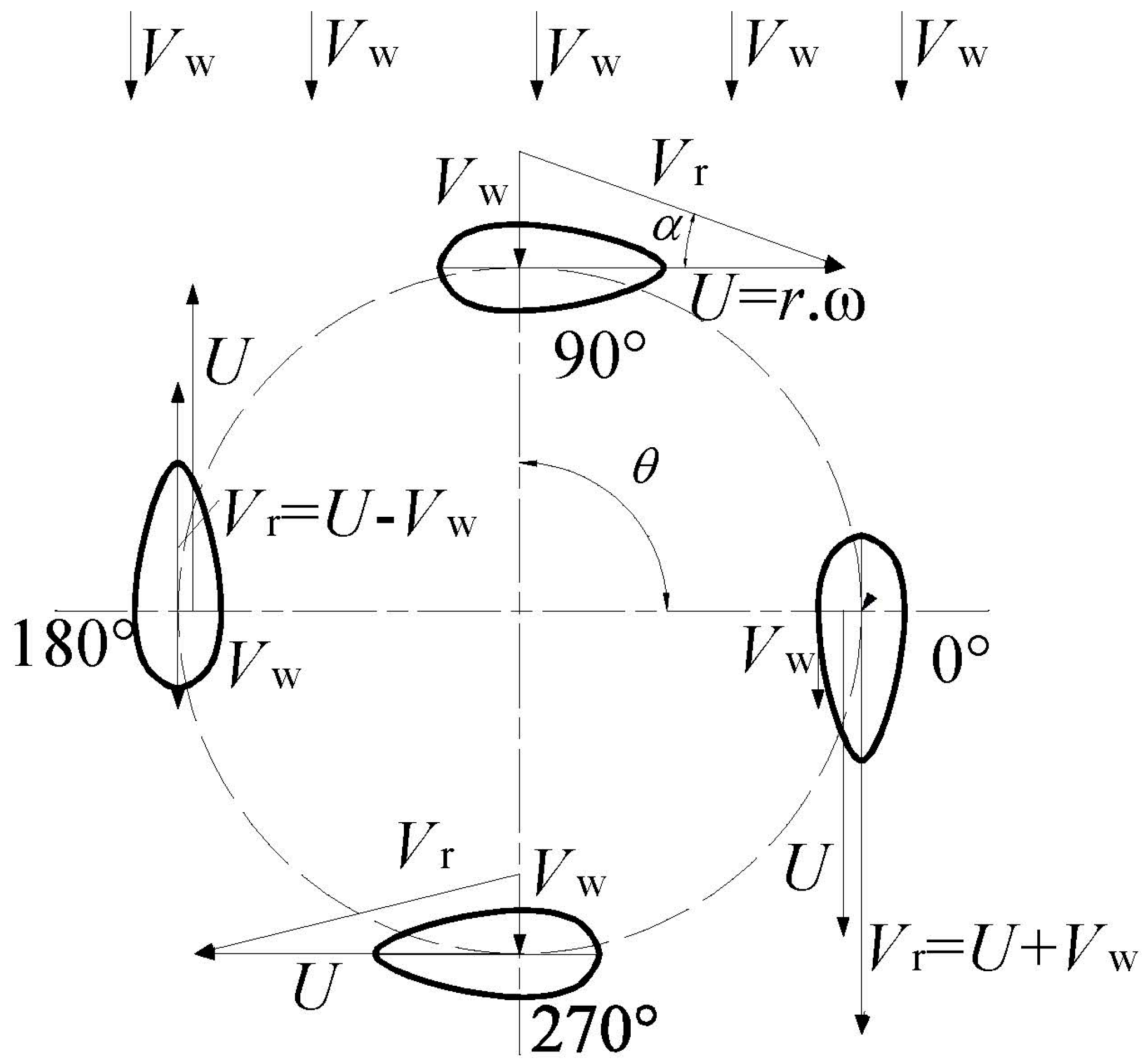
Figure 2.
Relative wind speed vectors in the upstream and downstream section.
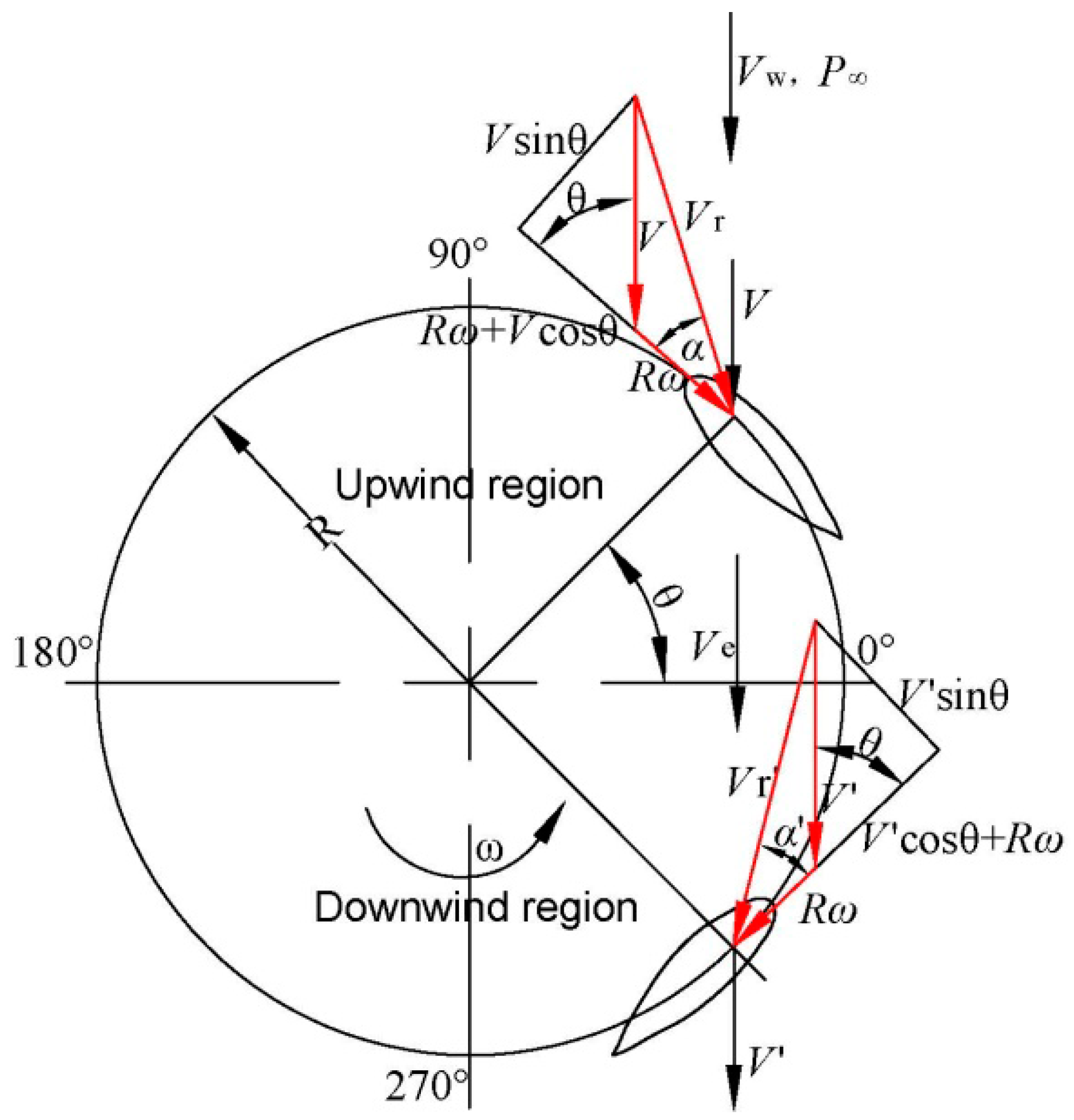
Figure 3.
Illustration of cyclical variable pitch.
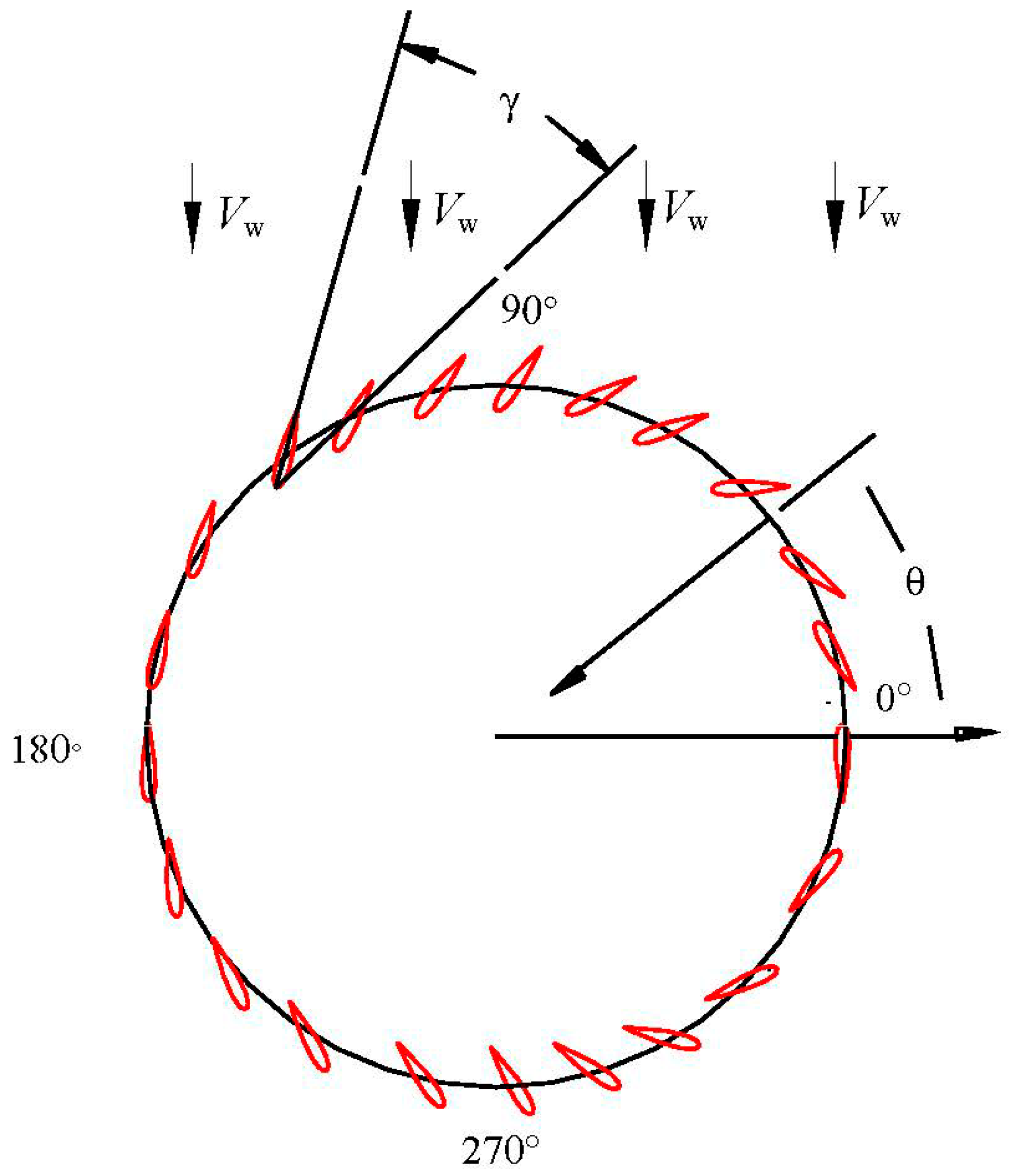
Figure 4.
Illustration cycloidal variable pitch.

Figure 5.
Local angle of attack as a function of the azimuthal angle. (a) AoA variation at different TSRs; (b) one pitching method at low TSR; (c) another pitching method at low TSR; (d) pitching method at rated TSR or higher TSR.
Figure 5.
Local angle of attack as a function of the azimuthal angle. (a) AoA variation at different TSRs; (b) one pitching method at low TSR; (c) another pitching method at low TSR; (d) pitching method at rated TSR or higher TSR.


Figure 6.
Curve of pitch angle in new approach.
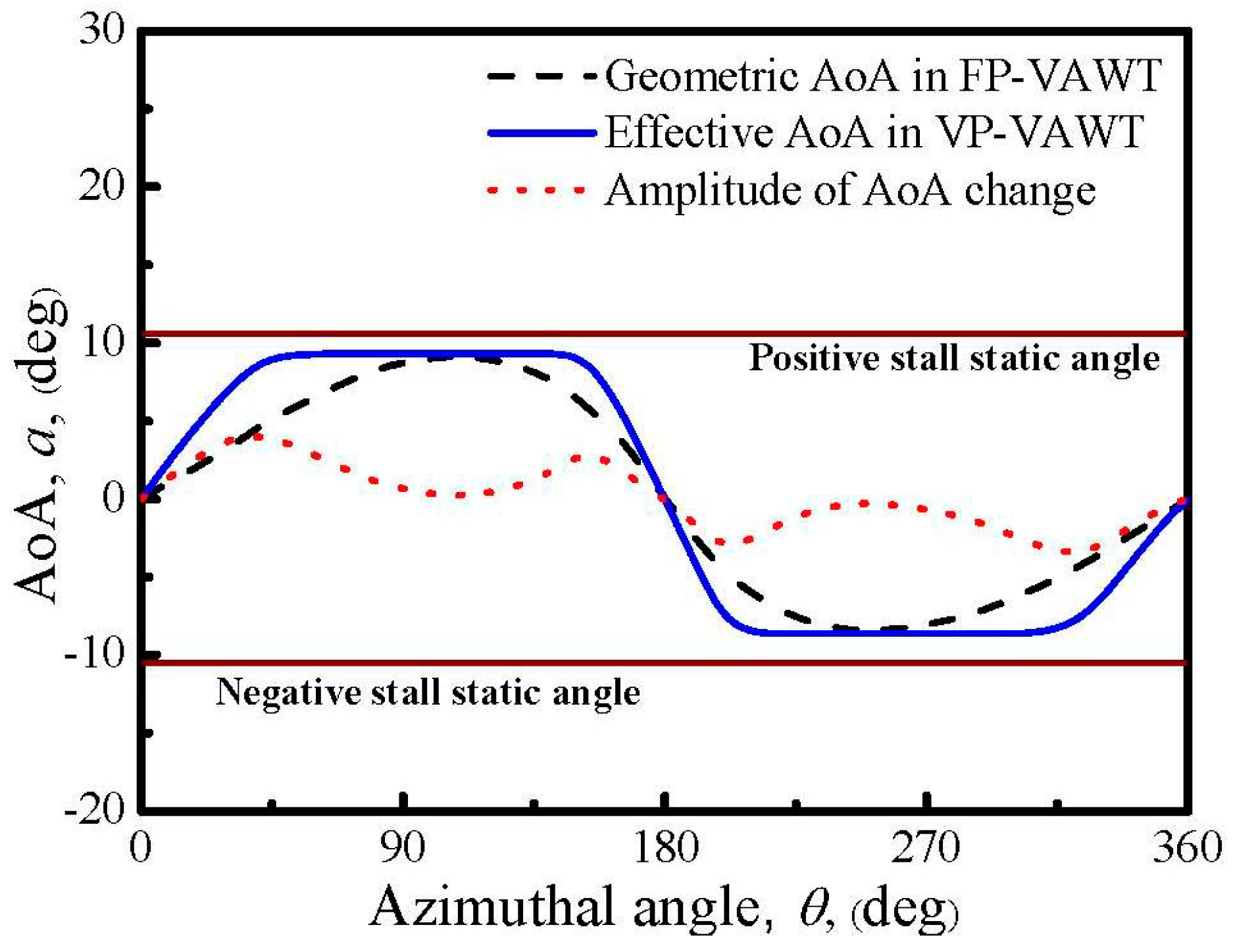
Figure 7.
Illustration of new variable pitch.

Figure 8.
Configuration of an H-type vertical-axis wind turbine (VAWT).
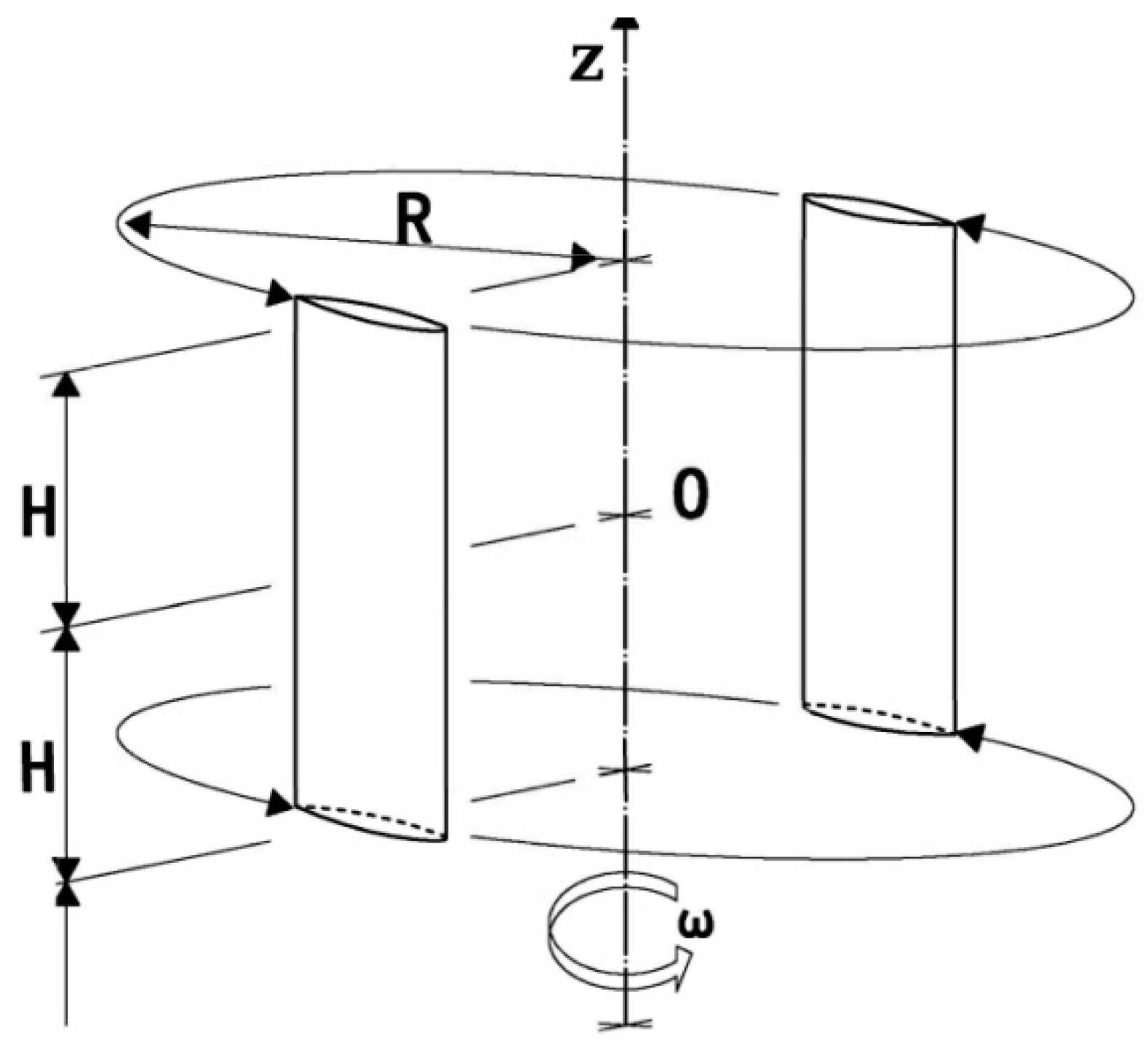
Figure 9.
Angle of attack (AoA) as a function of azimuthal angle in variable pitch (VP) and fixed pitch (FP) VAWTs. (a) TSR = 4; (b) TSR = 4.5; (c) TSR = 5; (d) TSR = 5.5.
Figure 9.
Angle of attack (AoA) as a function of azimuthal angle in variable pitch (VP) and fixed pitch (FP) VAWTs. (a) TSR = 4; (b) TSR = 4.5; (c) TSR = 5; (d) TSR = 5.5.

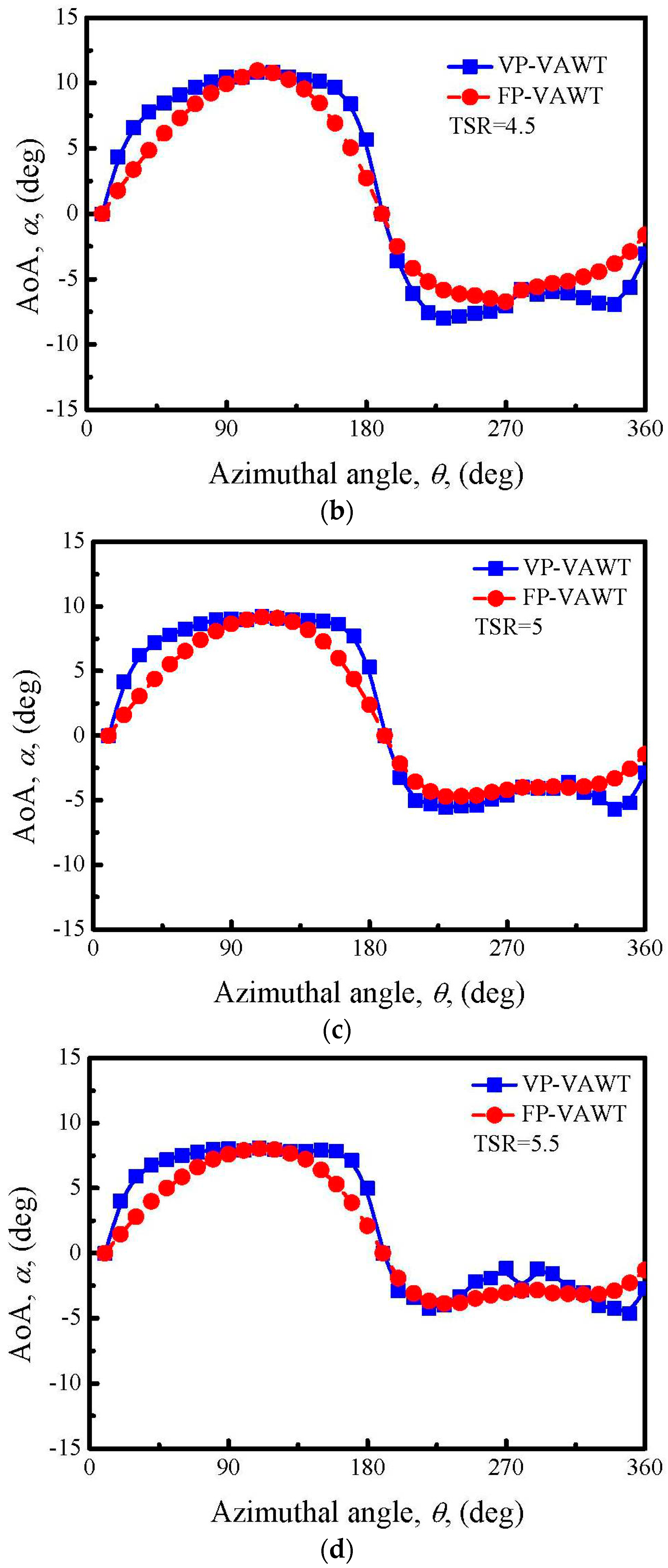
Figure 10.
Lift coefficient as a function of azimuthal angle in VP-VAWTs and FP-VAWTs. (a) TSR = 4; (b) TSR = 4.5; (c) TSR = 5; (d) TSR = 5.5.
Figure 10.
Lift coefficient as a function of azimuthal angle in VP-VAWTs and FP-VAWTs. (a) TSR = 4; (b) TSR = 4.5; (c) TSR = 5; (d) TSR = 5.5.
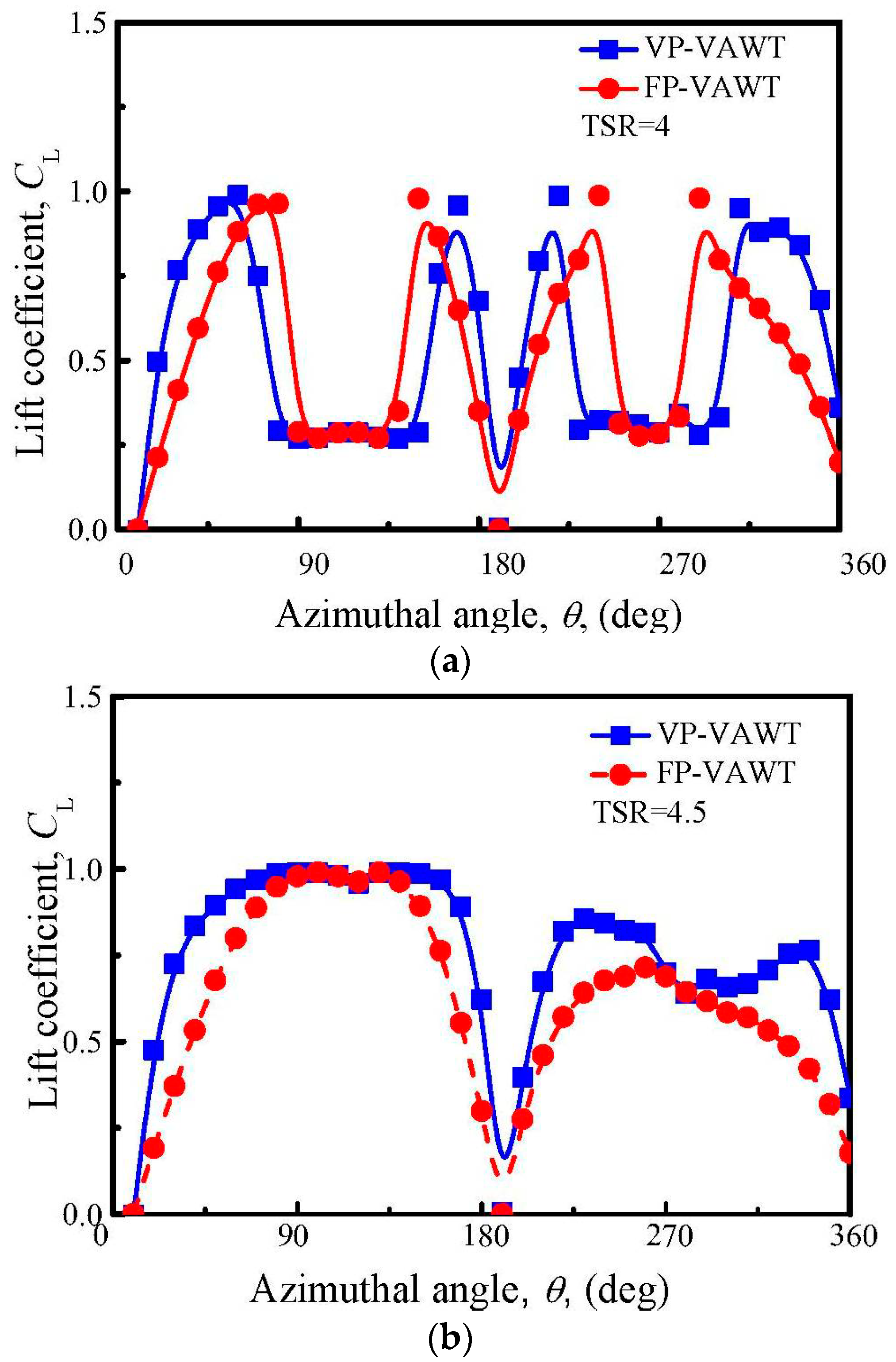

Figure 11.
Drag coefficient as a function of the azimuthal angle in VP-VAWTs and FP-VAWTs. (a) TSR = 4; (b) TSR = 4.5; (c) TSR = 5; (d) TSR = 5.5.
Figure 11.
Drag coefficient as a function of the azimuthal angle in VP-VAWTs and FP-VAWTs. (a) TSR = 4; (b) TSR = 4.5; (c) TSR = 5; (d) TSR = 5.5.

Figure 12.
Resultant velocity as a function of the azimuthal angles in VP-VAWTs and FP-VAWTs. (a) TSR = 4; (b) TSR = 4.5; (c) TSR = 5; (d) TSR = 5.5.
Figure 12.
Resultant velocity as a function of the azimuthal angles in VP-VAWTs and FP-VAWTs. (a) TSR = 4; (b) TSR = 4.5; (c) TSR = 5; (d) TSR = 5.5.
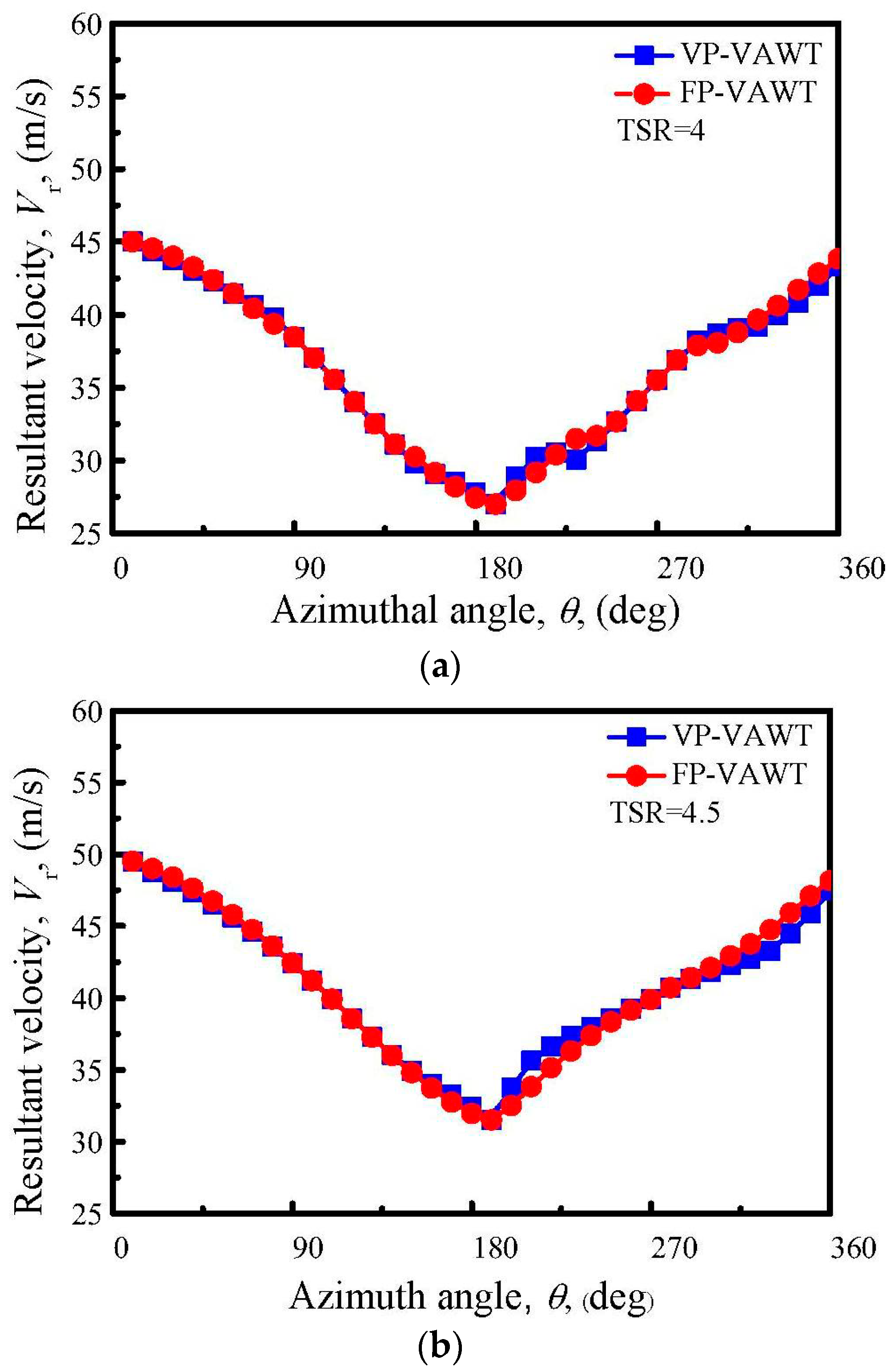

Figure 13.
Torque as a function of the azimuthal angles in VP-VAWTs and FP-VAWTs. (a) TSR = 4; (b) TSR = 4.5; (c) TSR = 5; (d) TSR = 5.5.
Figure 13.
Torque as a function of the azimuthal angles in VP-VAWTs and FP-VAWTs. (a) TSR = 4; (b) TSR = 4.5; (c) TSR = 5; (d) TSR = 5.5.
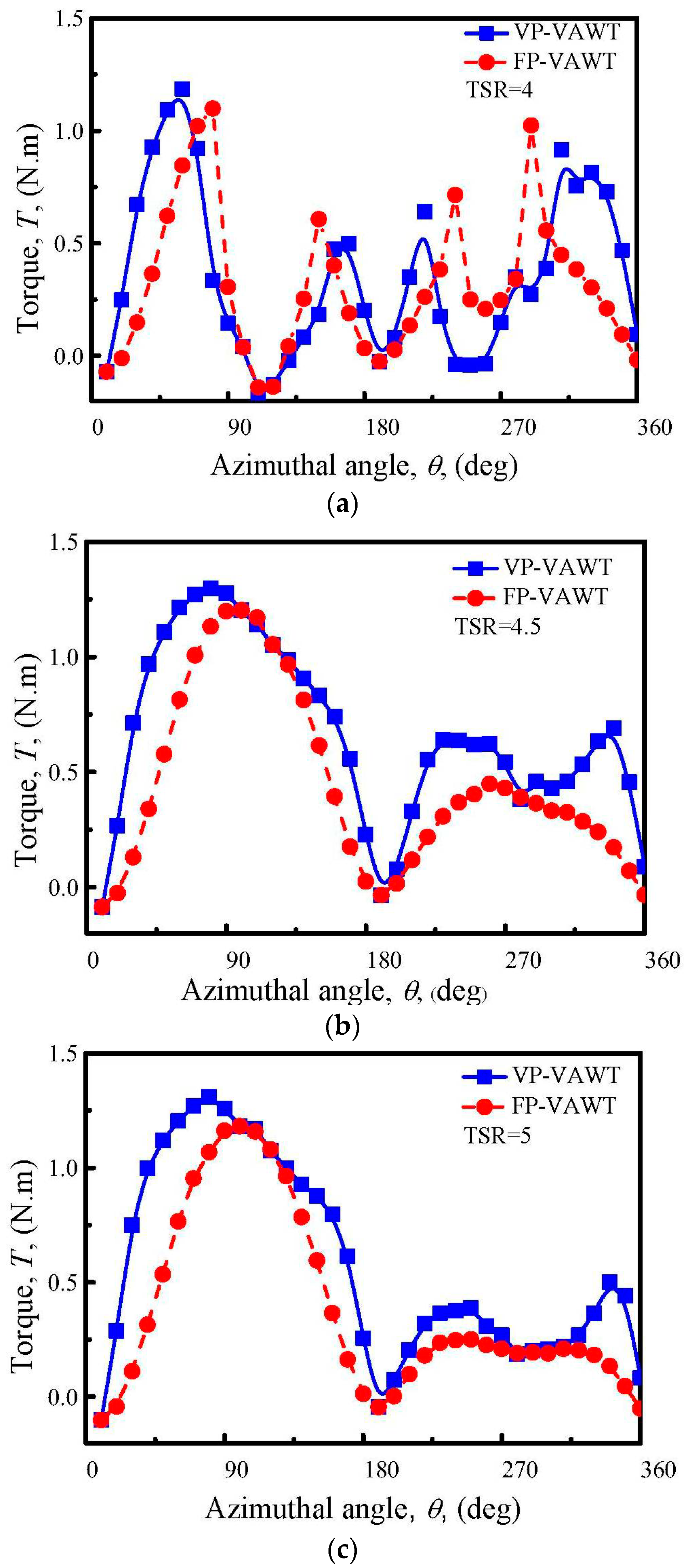
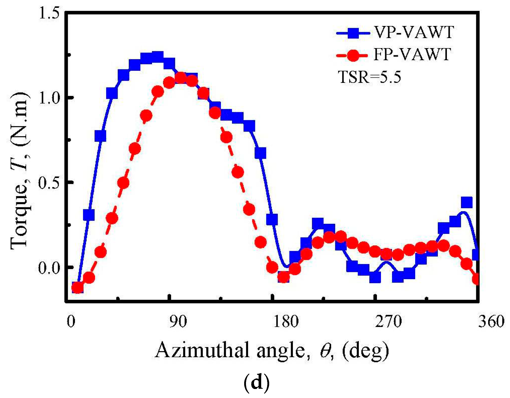
Figure 14.
Power output of a blade as a function of position in VP-VAWTs and FP-VAWTs. (a) TSR = 4; (b) TSR = 4.5; (c) TSR = 5; (d) TSR = 5.5.
Figure 14.
Power output of a blade as a function of position in VP-VAWTs and FP-VAWTs. (a) TSR = 4; (b) TSR = 4.5; (c) TSR = 5; (d) TSR = 5.5.

Figure 15.
Power coefficient curves of VP-VAWTs and FP-VAWTs.

© 2018 by the authors. Licensee MDPI, Basel, Switzerland. This article is an open access article distributed under the terms and conditions of the Creative Commons Attribution (CC BY) license (http://creativecommons.org/licenses/by/4.0/).
Share and Cite
MDPI and ACS Style
Zhao, Z.; Wang, R.; Shen, W.; Wang, T.; Xu, B.; Zheng, Y.; Qian, S. Variable Pitch Approach for Performance Improving of Straight-Bladed VAWT at Rated Tip Speed Ratio. Appl. Sci. 2018, 8, 957. https://doi.org/10.3390/app8060957
AMA Style
Zhao Z, Wang R, Shen W, Wang T, Xu B, Zheng Y, Qian S. Variable Pitch Approach for Performance Improving of Straight-Bladed VAWT at Rated Tip Speed Ratio. Applied Sciences. 2018; 8(6):957. https://doi.org/10.3390/app8060957
Chicago/Turabian StyleZhao, Zhenzhou, Ruixin Wang, Wenzhong Shen, Tongguang Wang, Bofeng Xu, Yuan Zheng, and Siyue Qian. 2018. "Variable Pitch Approach for Performance Improving of Straight-Bladed VAWT at Rated Tip Speed Ratio" Applied Sciences 8, no. 6: 957. https://doi.org/10.3390/app8060957
Note that from the first issue of 2016, this journal uses article numbers instead of page numbers. See further details here.