Wind Turbine Generator Efficiency Based on Powertrain Combination and Annual Power Generation Prediction


1
Department of Mechanical Engineering, Graduate School of Gachon University, Seongnam 13120, Korea
2
Korea Electric Power Research Institute, Daejeon 34056, Korea
3
Department of Mechanical Engineering, Gachon University, Seongnam 13120, Korea
*
Author to whom correspondence should be addressed.
Appl. Sci. 2018, 8(6), 858; https://doi.org/10.3390/app8060858
Submission received: 28 April 2018
/
Revised: 18 May 2018
/
Accepted: 21 May 2018
/
Published: 24 May 2018
(This article belongs to the Section Mechanical Engineering)
Abstract
:Featured Application
SimulationX is graphical-user-interface-based commercial software that is considerably useful for developing and analyzing a mechanical system as a single simulation environment because it can be easily applied in various research fields such as structural analysis, flow analysis, controllers, and dynamics.
Abstract
Wind turbine generators are eco-friendly generators that produce electric energy using wind energy. In this study, wind turbine generator efficiency is examined using a powertrain combination and annual power generation prediction, by employing an analysis model. Performance testing was conducted in order to analyze the efficiency of a hydraulic pump and a motor, which are key components, and so as to verify the analysis model. The annual wind speed occurrence frequency for the expected installation areas was used to predict the annual power generation of the wind turbine generators. It was found that the parallel combination of the induction motors exhibited a higher efficiency when the wind speed was low and the serial combination showed higher efficiency when wind speed was high. The results of predicting the annual power generation considering the regional characteristics showed that the power generation was the highest when the hydraulic motors were designed in parallel and the induction motors were designed in series.
1. Introduction
1.1. Research Background
As carbon dioxide emission control has strengthened, owing to the concerns over limited resources and environmental pollution, an interest in eco-friendly energy production technologies, such as solar photovoltaic power generation and wind turbines, has been growing [1]. Among them, the wind turbine generators that use aerodynamics have been extensively researched and developed, because they can be easily installed even in a rough terrain or the ocean.
The main components of the existing wind turbine generators are gearboxes, generators, and frequency converters. However, it has been reported that the major failures of wind turbine generators occur in the main components, and an interest in maintenance has been increasing since one to three failures occur in each wind turbine generator every year [2,3,4,5]. In recent years, the development of permanent magnet generators, using rare earth, has allowed for the development of small-sized generators with a high torque density. However, the requirement for 600–800 kg rare earth per MW may significantly affect development costs. Furthermore, generators with high torque density may contribute to light weight, but the fundamental problems with maintenance cannot be addressed [6]. The maintenance costs of wind turbine generators are significantly affected by the structure complexity and marine conditions. Wind turbine generators with hydraulic transmission systems have been proposed to overcome such problems [7].
The stability of the internal components of wind turbine generators significantly affects the power quality, and the generating voltage and frequency must be as stable as possible in order to produce high-quality power [8]. Hydraulic transmission can maintain the output at an almost constant voltage and frequency by continuously controlling the capacity of the hydraulic motor according to the variable wind speed conditions. Therefore, it is possible to produce high-quality power, even if the gearbox and frequency converter, which experience classic problems, are removed, in which case the safety circuit becomes relatively simpler [9]. In addition, as the generator can be moved to the ground, only the hydraulic pump is installed in the nacelle, making it possible to reduce the head mass by 20–40% and tower mass by up to 50%, as well as to significantly save on maintenance costs [10]. However, as hydraulic transmission has a lower overall system efficiency compared to mechanical transmission, a detailed study on power generation efficiency is required for system development [11,12].
1.2. Requirement for Analysis Technology
Hydraulic systems have been applied in various areas, such as power plants, construction machinery, aircraft, automobiles, and agricultural machinery, because they are easy to control and their power density is high. However, as hydraulic systems are still being developed using a trial-and-error method, in which the problems are addressed by improving and replacing each component, they require considerable time and cost for research and development. In addition, the introduction of an electronic control has increased the system complexity and the number of parameters that need to be considered for the design, thereby significantly increasing the amount of time and investment cost that is required for product development.
In particular, large equipment, such as wind turbine generators, require considerable time and cost for prototype fabrication, performance testing, and efficiency evaluation. Furthermore, it is significantly difficult to analyze the system performance for design change and to examine component compatibility. However, the advances in computer performance have made it possible to simulate complicated systems with high accuracy. Such computer aided engineering is being applied to the development of numerous products, because it enables various requirements to be examined from the initial development stage and may considerably reduce the cost and time that are required for prototype fabrication.
1.3. Aim of this Study
In this study, a system simulation environment was developed using SimulationX (3.8), which is commercial software, to save on the time and cost that is required for research and development. The main components of a hydraulic system were tested for performance so as to verify the reliability of the analysis model. In addition, the power generation efficiency of a wind turbine generator with hydraulic transmission was analyzed through powertrain combination using the developed simulation environment, and the optimal powertrain combination was confirmed by predicting the annual power generation, considering the regional characteristics.
2. Methods
Simulation model development was divided into map base modeling, which was based on specifications and design base modeling, which was based on drawings, depending on the application. In this study, the analysis model was developed using map base modeling, which was suitable for system performance prediction. For analysis model development, the logical feasibility was sufficiently examined for the component model and the more complicated models, and the logic of the analysis model for the main performances was examined by constructing a system. However, the details of the analysis model development procedure were not included, because they were not considered appropriate for the purpose of this study.
2.1. Wind Turbine Generator System Configuration
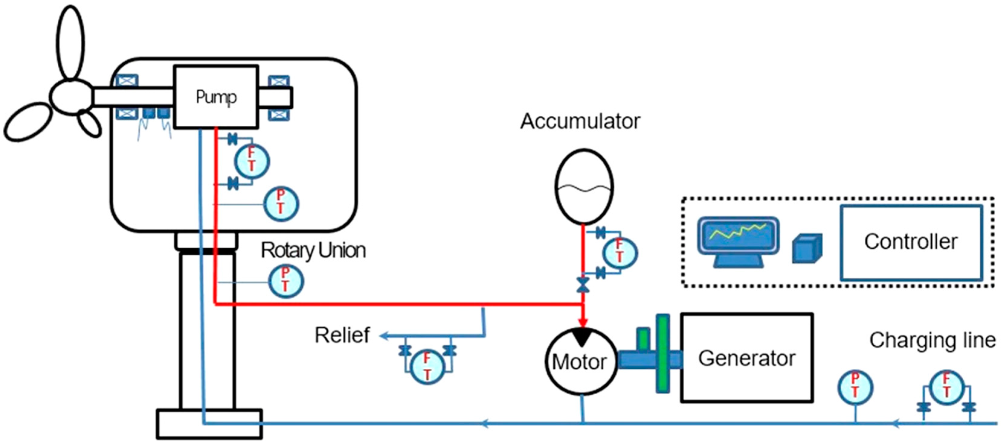
In a wind turbine generator system, the rotation of a blade that was caused by the wind force supplied mechanical energy to a hydraulic pump, which then converted the mechanical energy into fluid energy. The fluid energy was supplied to a hydraulic motor, which converted it into mechanical energy and drove an electric motor to produce electric energy.
Figure 1 shows the schematic diagram of the wind turbine generator system that was targeted in this study. It basically consisted of a hydraulic pump, a hydraulic motor, a controller, and control valves [13,14]. Even though there were safety and auxiliary circuits in the detailed circuit of the wind turbine generator, they were not considered in this study because they did not affect the characteristics of the system combinations, but they could have had an adverse effect on obtaining analysis results rapidly.
2.2. Component Test to Verify the Analysis Model
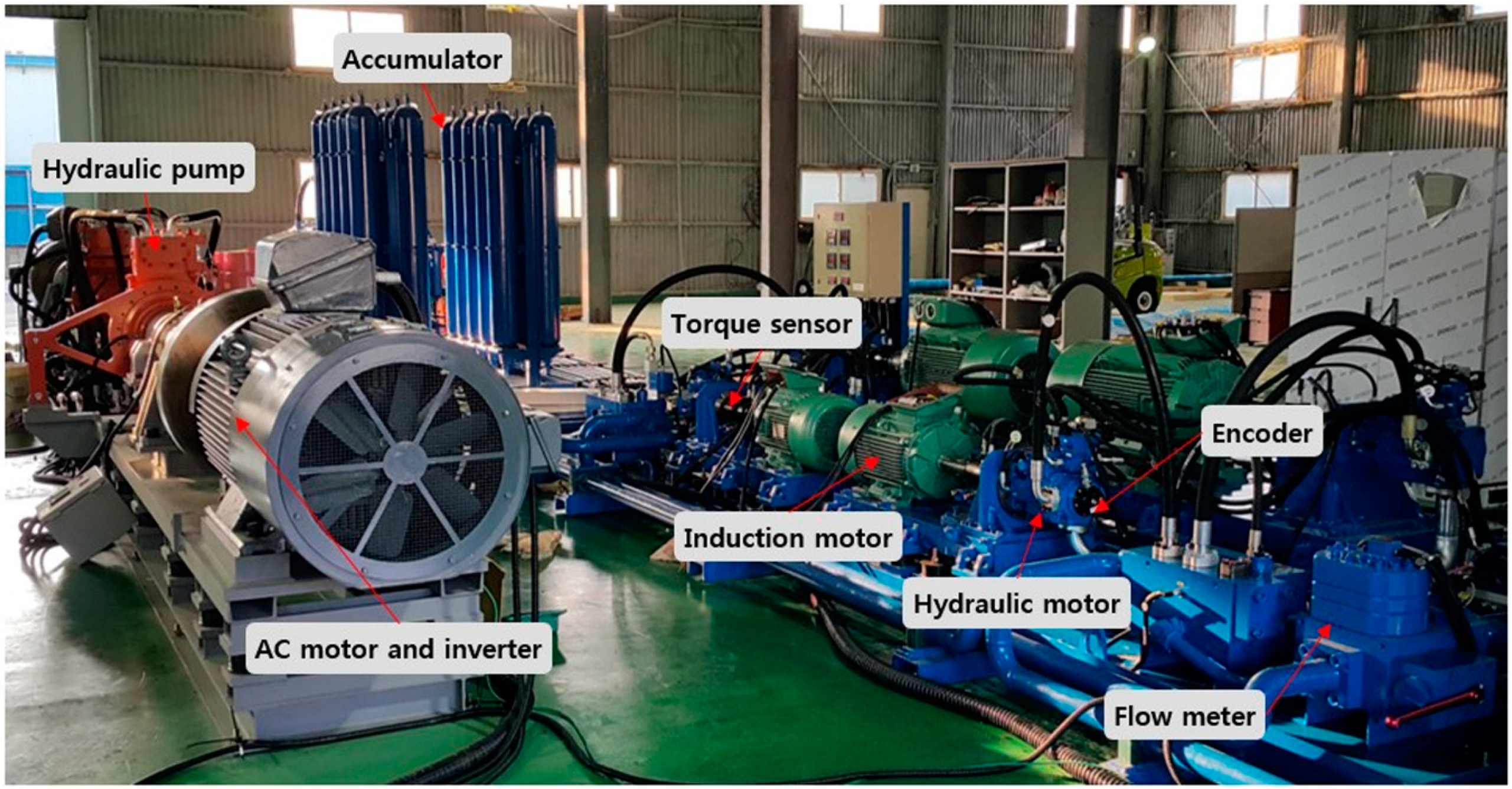
A test setup was prepared, as shown in Figure 3, so as to measure the efficiency of the hydraulic pump and hydraulic motor, which were the major components of the target wind turbine generator system. In the test setup, a rotation speed sensor was installed to measure the volumetric efficiency and a torque sensor was used to examine the overall efficiency. The mechanical efficiency was calculated using the measured volumetric efficiency and overall efficiency. The hydraulic pump measured the pump efficiency according to the load, based on rotation speed, and the hydraulic motor measured the motor efficiency according to the load, based on capacity, because the variable capacity was used. Each measurement result was used for the analysis model verification.
2.3. Analysis Model Development
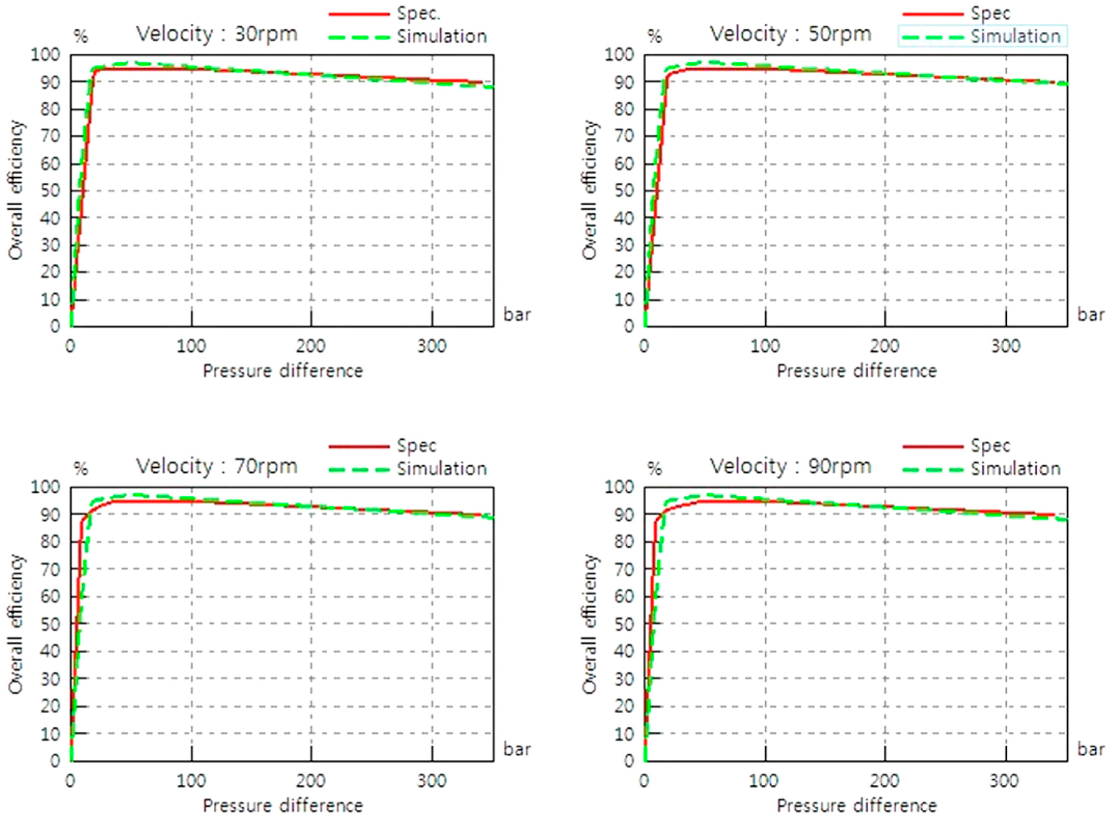
A radial-type piston pump, which was suitable for low speed and high torque, was used as the hydraulic pump of the wind turbine. A study reported that the efficiency of the hydraulic pump that was applied to the wind turbine generators was more than 90% in a steady state [15]. Figure 4 compares the test results with the simulation results of the analysis model. The test results confirmed that an overall efficiency of more than 88% was secured in the operating range.
Figure 5 shows the simulation and test results of the hydraulic motor. The hydraulic motor exhibited a low efficiency in low-pressure areas, and its efficiency decrease with capacity. This is because the mechanical efficiency of the hydraulic motor was low in low-speed areas, owing to its structural characteristics.
As the reliability of the analysis model significantly affected the system design when the system analysis was conducted using simulation, it needed to have been verified before the simulation model was utilized. The simulation and test results for the hydraulic motor and hydraulic pump were extremely similar, which indicated that there was no problem conducting a system analysis using simulation.
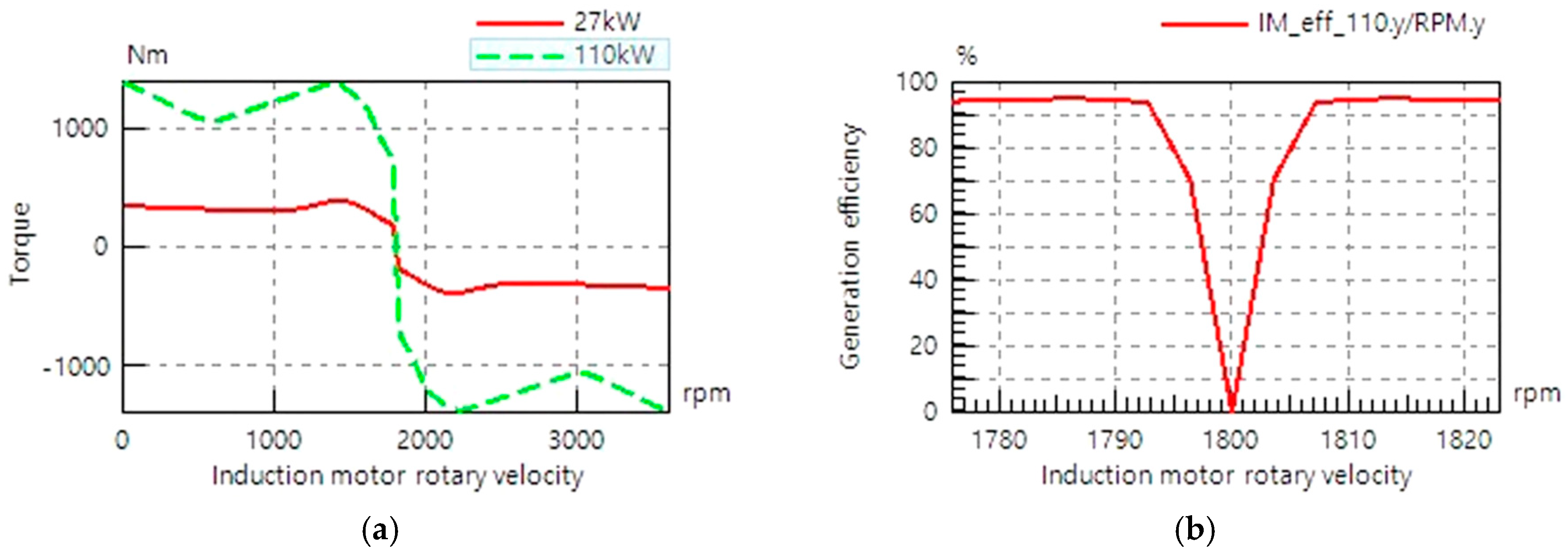
Figure 6 shows the analysis results and model of the induction motor. The model was developed using the specifications that were provided by the product manufacturer. Furthermore, the analysis model was developed so that power generation could be calculated by considering the efficiency of the induction motor, using the provided rated output power and efficiency.
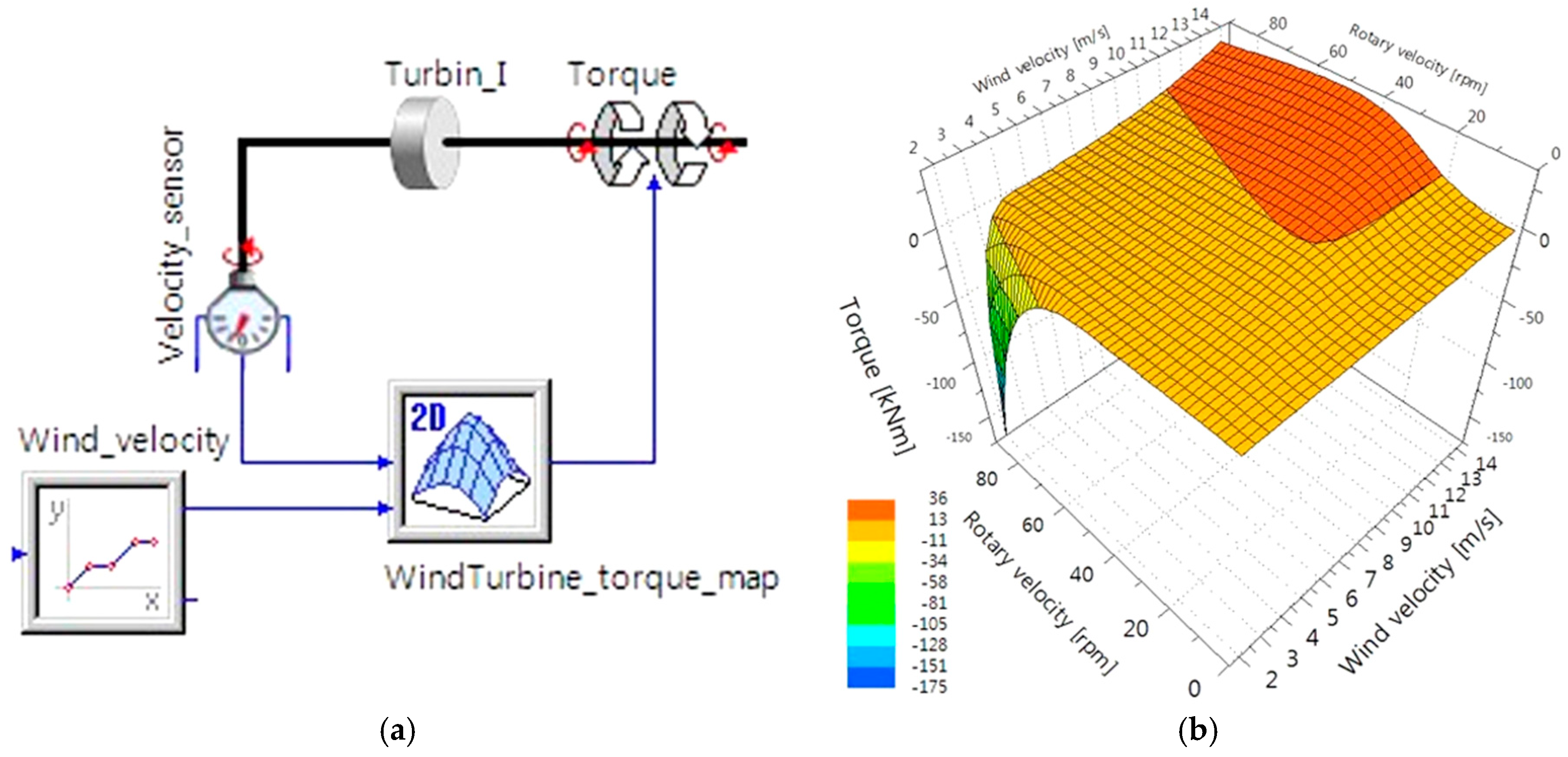
A nonlinear aerodynamic model was required so as to design the blade of a wind turbine, and a detailed analysis was generally conducted using CFD (computational fluid dynamics), because there was also an influence of turbulence. In addition, the turbine blade was one of the key technologies for wind turbine generators, because damage that amounted to 10–20% of the total power was caused by wind turbine wakes [16,17]. As the efficiency of the blade affected the quantitative annual power generation but not the powertrain combination efficiency, the turbine blade model was developed using a two-dimensional (2D) map, so that mechanical torque could be entered according to the rotation speed of the blade and wind speed. The 2D map was derived using the Simulink software. Figure 7 shows the 2D map and analysis model.
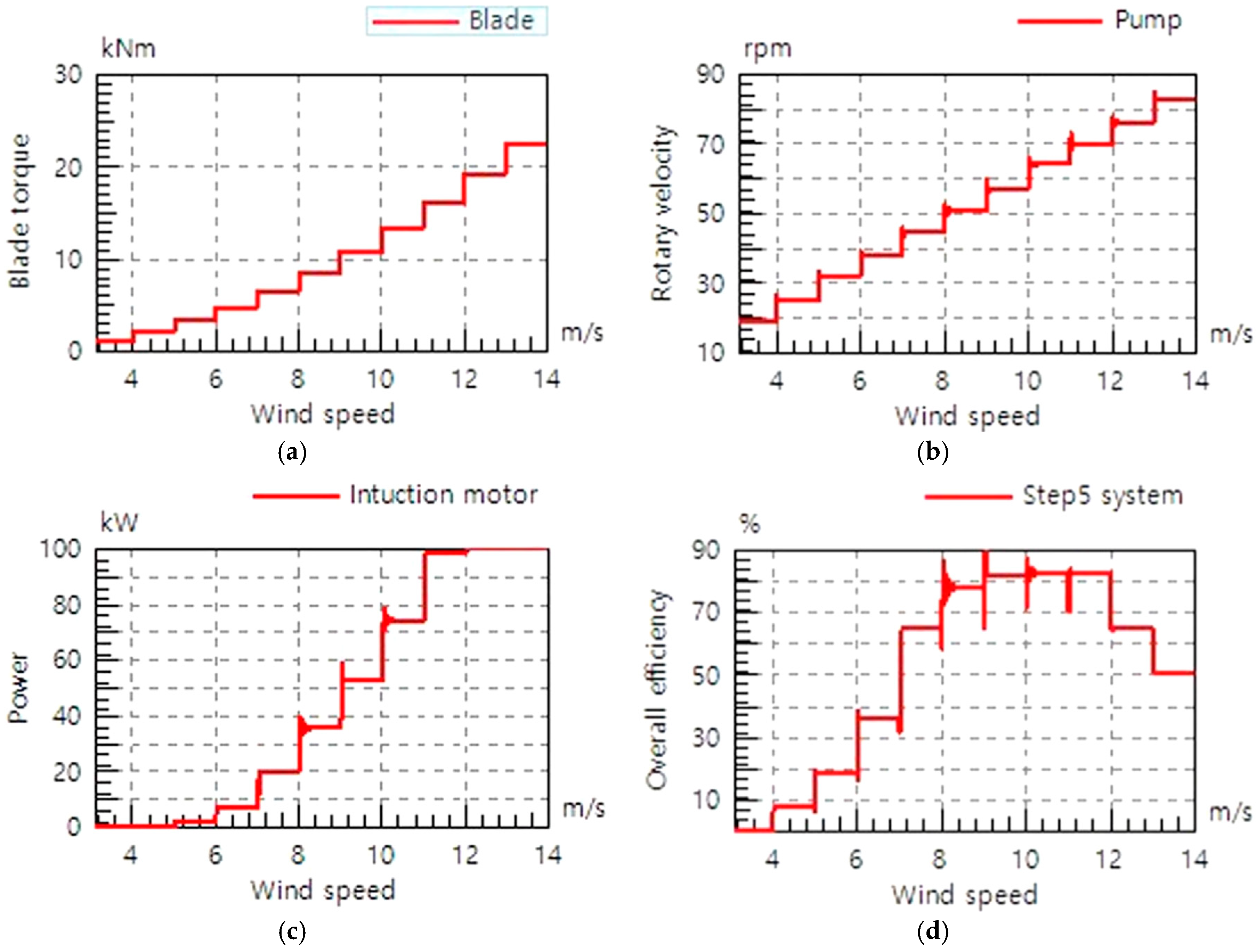
Figure 8 shows the system analysis model for step 5, and Figure 9 shows the simulation results that were used to examine the basic performance. The simulation results showed that the power generation efficiency of step 5 was low when the wind speed was low, and it was more than 80% when wind speed was 8–12 m/s. In addition, the generated power was saturated and the power generation efficiency declined sharply when the wind speed exceeded 12 m/s, because the maximum generated power of the induction motor was limited to 100 kWh.
3. Results
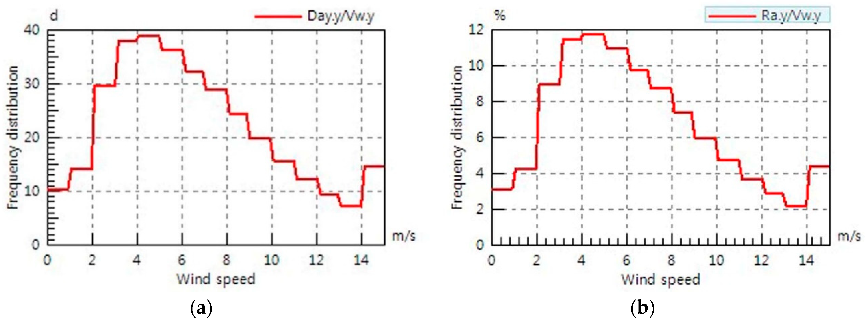
As the wind turbine generators exhibited a significant difference in power generation, depending on the installation area, the wind speed occurrence frequency for the installation area needed to be investigated first. Figure 10 shows the annual wind speed occurrence frequency in Muan, Jeollanam-do, which was an expected installation area, based on the wind speed measurement data in the area. A wind speed of 4 m/s exhibited the highest frequency.
3.1. System Efficiency Analysis
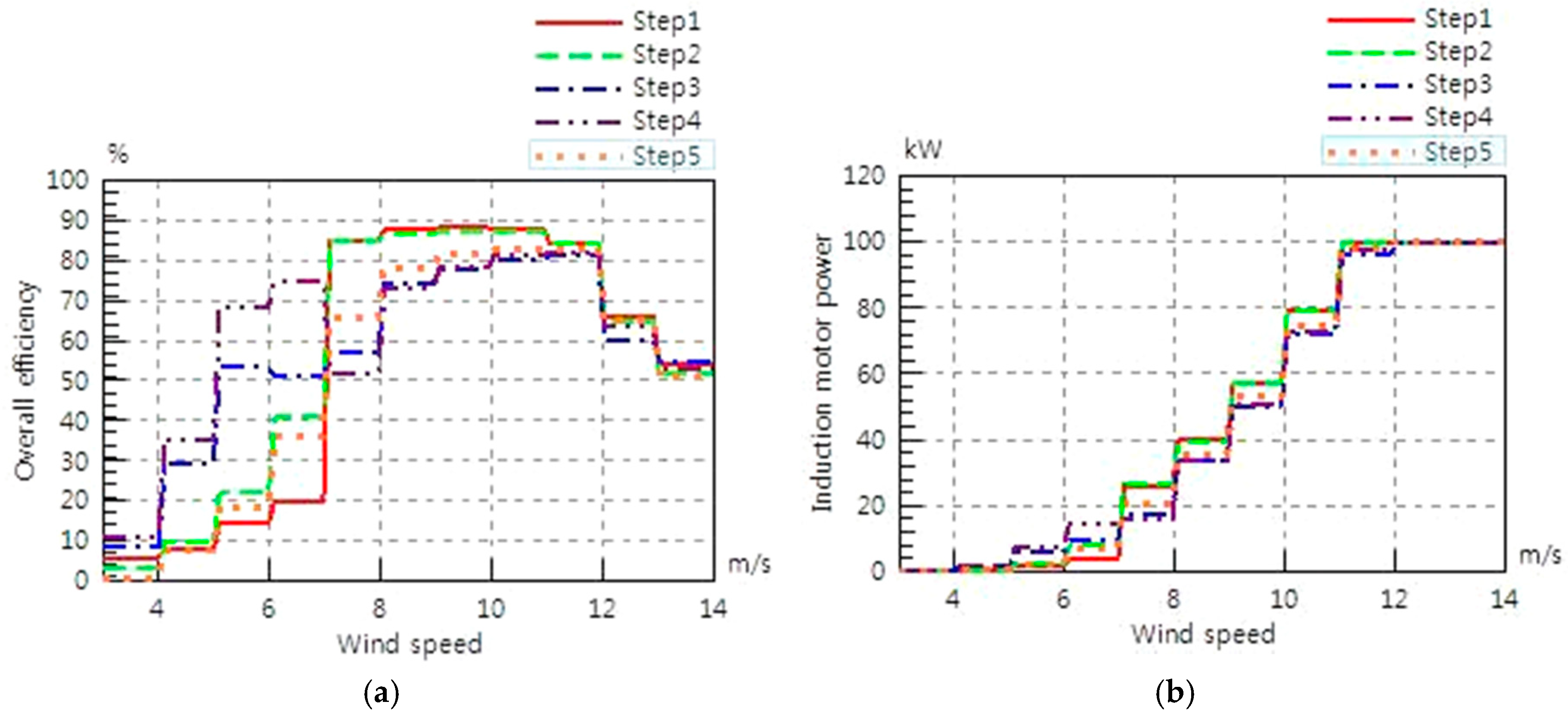
Figure 11 shows the overall system efficiency and generated power of the wind turbine generator for different powertrain combinations. The generated power was saturated when the wind speed exceeded 11 m/s for the serial combinations (step 1 and step 2) and 12 m/s for the parallel combinations (step 3 and step 4), and the single pump and motor combination (step 5). In addition, the power generation efficiency was higher in the serial combinations when the wind speed was higher than 7 m/s. It was higher in the parallel combinations when wind speed was lower than 7 m/s.
3.2. Annual Power Generation Prediction
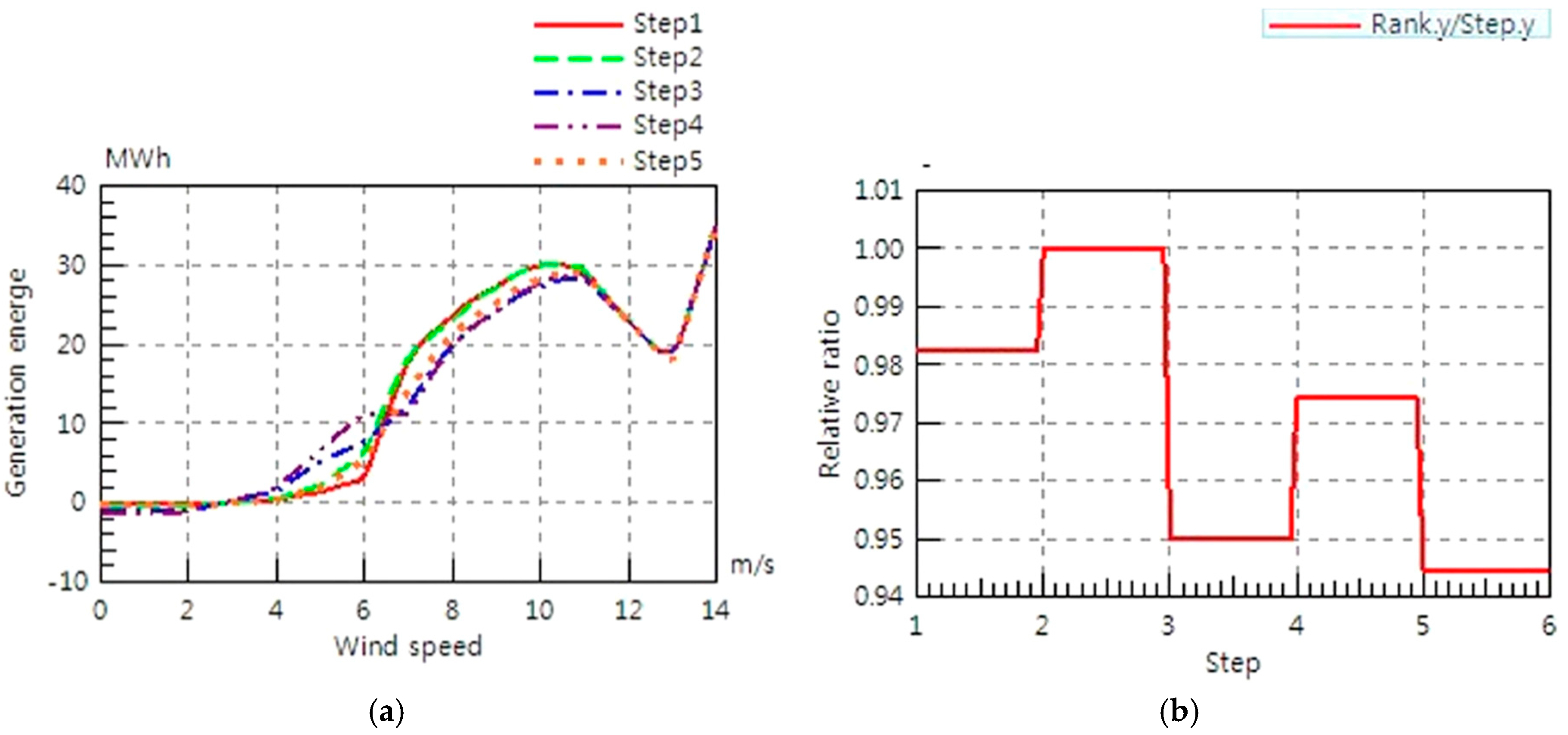
The optimal powertrain combination, which considered the system efficiency and the annual power generation, could be derived using the wind speed occurrence frequency, shown Figure 10, and the power generated at different wind speeds, predicted in Figure 11. Figure 12 shows the generated energy according to the wind speed and the optimal combination. Step 2 exhibits the highest power generation, and step 5, which is a serial combination, shows the lowest annual power generation.
4. Conclusions
In this study, a simulation analysis model was developed in order to rapidly analyze the system characteristics of a wind turbine generator, using powertrain combination. Before the system construction, the system power generation efficiency and annual power generation were predicted using simulation. The results of this study could be summarized as follows:
- The overall efficiency was examined by testing the performances of a hydraulic pump and a hydraulic motor with hydrostatic transmission, which were the key components of wind turbine generators. In particular, it was confirmed that the overall efficiency decreased with the capacity of the hydraulic motor.
- The serial combination of generators exhibited a higher power generation efficiency when the wind speed was higher than 7 m/s, while the parallel combination showed a higher power generation efficiency when the wind speed was lower than 7 m/s.
- The analysis of e annual power generation energy, which considered the regional characteristics, showed that step 2, which was a combination of the parallel hydraulic motor and serial generator, was the optimal combination and step 5, which was the combination of the large-capacity pump and motor, was the worst combination.
- It was confirmed that power generation efficiency declined sharply when the wind speed exceeded 10–11 m/s, because the maximum power generation capacity of the induction motor was limited. This indicated that the maximum power generation capacity needed to be determined, considering the regional characteristics for designing a wind turbine generator.
- It was possible to predict system performance before the system construction and to systematically and specifically approach problems that may have arisen after the system construction using a simulation model.
- The system performance could be analyzed using an analysis model for designing the controller and blade of a wind turbine generator. This would save the time and cost that were required for research and development.
- The major disadvantage of using a simulation in the concept design stage, was that it could not perform the performance test on all of the components. Therefore, the performance tests on all of the components are required.
- The system will be assembled based on the results of this study, and a full system performance test will be performed. In addition, the verification of the full analytical model will be required before applying it to the various fields that use analytical models.
Author Contributions
Drafting of manuscript: D.K.; acquisition of design parameters: B.P.; model and analysis: D.K.; planning of research: B.P.; and supervision of the research: J.J.
Acknowledgments
The author thanks Kyungsik Choi at the Korea Electric Power Research Institute for supplying the research materials used in this paper.
Conflicts of Interest
The authors declare no conflict of interest.
References
- Höhn, B.R. Future transmissions for wind turbines. Appl. Mech. Mater. 2011, 86, 18–25. [Google Scholar] [CrossRef]
- Jones, J.A.; Bruce, A.; Lam, A.S. Advanced performance hydraulic wind energy. In Proceedings of the 5th IEEE Green Technologies Conference, Denver, CO, USA, 4–5 April 2013. [Google Scholar]
- Fan, Y.; Mu, A.; Ma, T. Study on the application of energy storage system in offshore wind turbine with hydraulic transmission. Energy Convers. Manag. 2016, 110, 338–346. [Google Scholar] [CrossRef]
- Thomsen, K.E.; Dahlhaug, O.G.; Niss, M.O.K.; Haugset, S.K. Technological advances in hydraulic drive trains for wind turbines. Energy Procedia 2012, 24, 76–82. [Google Scholar] [CrossRef]
- Spinato, F.; Tavner, P.J.; Van Bussel, G.J.W.; Koutoulakos, E. Reliability of wind turbine subassemblies. IET Rene. Power Gener. 2009, 3, 1–15. [Google Scholar] [CrossRef]
- Jensen, B.B.; Mijatovic, N.; Abrahamsen, A.B. Development of superconducting wind turbine generators. J. Renew. Sustain. Energy 2013, 5. [Google Scholar] [CrossRef]
- Skaare, B.; Hörnsten, B.; Nielsen, F.G. Modeling, simulation and control of a wind turbine with a hydraulic transmission system. Wind Energy 2013, 16, 1259–1276. [Google Scholar] [CrossRef]
- Muljadi, E.; Butterfield, C.P.; Chacon, J.; Romanowitz, H. Power quality aspects in a wind power plant. In Proceedings of the IEEE Power Engineering Society General Meeting, Montreal, QC, Canada, 18–22 June 2006. [Google Scholar]
- Chen, W.; Gao, F.; Meng, X.; Ren, A.; Zhou, S. An offshore hydraulic wind turbine generator with variable-diameter rotor: Design, modeling and experiment. Proc. IMechE Part M 2017, 231, 521–532. [Google Scholar] [CrossRef]
- Qin, C.; Innes-Wimsatt, E.; Loth, E. Hydraulic-electric hybrid wind turbines: Tower mass saving and energy storage capacity. Renew. Energy 2016, 99, 69–79. [Google Scholar] [CrossRef]
- Polinder, H.; Ferreira, J.A.; Jensen, B.B.; Abrahamsen, A.B.; Atallah, K.; McMahon, R.A. Trends in wind turbine generator systesms. IEEE J. Emerg. Sel. Top. Power Electron. 2013, 1, 174–185. [Google Scholar] [CrossRef]
- Silva, P.; Giuffrida, A.; Fergnani, N.; Macchi, E.; Cantù, M.; Suffredini, R.; Schiavetti, M.; Gigliucci, G. Performance prediction of a multi-MW wind turbine adopting an advanced hydrostatic transmission. Energy 2014, 64, 450–461. [Google Scholar] [CrossRef]
- Dolan, B.; Aschemann, H. Control of a wind turbine with a hydrostatic transmission—An extended linearisation approach. In Proceedings of the 17th International Conference on Methods & Models in Automation & Robotics (MMAR), Miedzyzdrojie, Poland, 27–30 August 2012. [Google Scholar]
- Izadian, A.; Hamzehlouia, S.; Deldar, M.; Anwar, S. A Hydraulic wind power transfer system: Operation and modeling. IEEE Trans. Sustain. Energy 2014, 5, 457–465. [Google Scholar] [CrossRef]
- Mortensen, K.A.; Henriksen, K.H. Efficiency Analysis of a Radial Piston Pump Applied in a 5MW Wind Turbine with Hydraulic Transmission. Master’s Thesis, Aalborg University, Aalborg, Denmark, 31 May 2011. [Google Scholar]
- Barthelmie, R.J.; Hansen, K.; Frandsen, S.T.; Rathmann, O.; Schepers, J.G.; Schlez, W.; Phillips, J.; Rados, K.; Zervos, A.; Politis, E.S.; et al. Modelling and measuring flow and wind turbine wakes in large wind farms offshore. Wind Energy 2009, 12, 431–444. [Google Scholar] [CrossRef]
- Nelson, B.; Kouh, J.S. The aerodynamic analysis of a rotating wind turbine by viscous-coupled 3D panel method. Appl. Sci. 2017, 7, 551. [Google Scholar] [CrossRef]
Figure 1.
Schematic diagram of the wind turbine generator.

Figure 2.
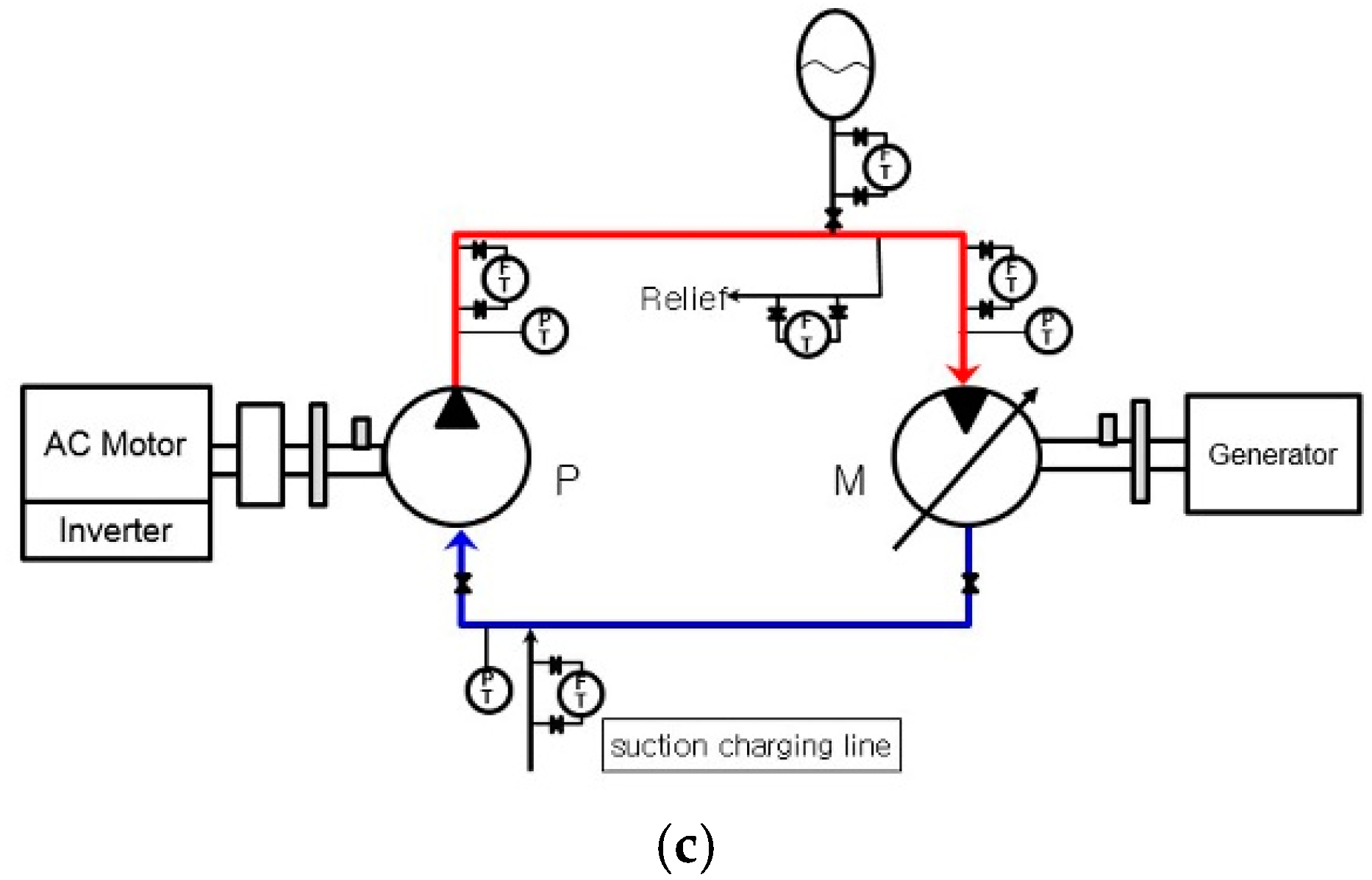
Wind turbine generator powertrain combinations. (a) Step 1–2: parallel hydraulic motor and serial induction motor; (b) Step 3–4: parallel hydraulic motor and parallel induction motor; and (c) Step 5: large-capacity pump and large-capacity hydraulic motor.
Figure 2.
Wind turbine generator powertrain combinations. (a) Step 1–2: parallel hydraulic motor and serial induction motor; (b) Step 3–4: parallel hydraulic motor and parallel induction motor; and (c) Step 5: large-capacity pump and large-capacity hydraulic motor.
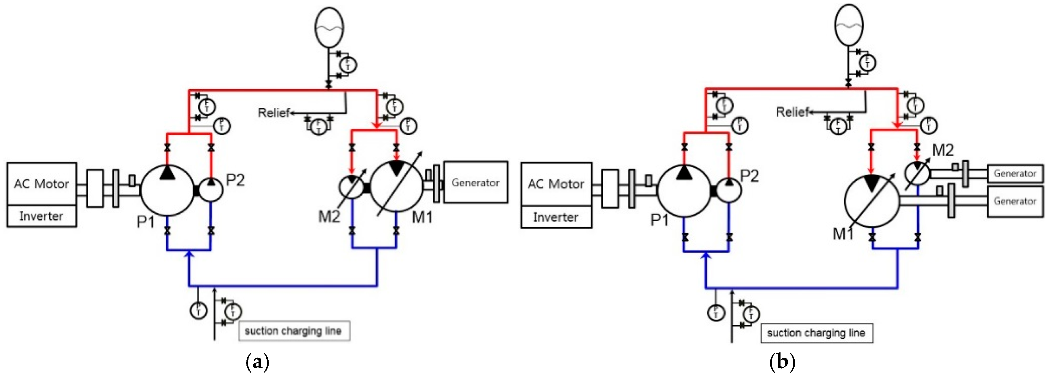

Figure 3.
Development of a simulation environment of the wireline riser tensioning system.

Figure 4.
Results of the simulation and test of the hydraulic pump.

Figure 5.
Results of the simulation and test of the hydraulic motor.
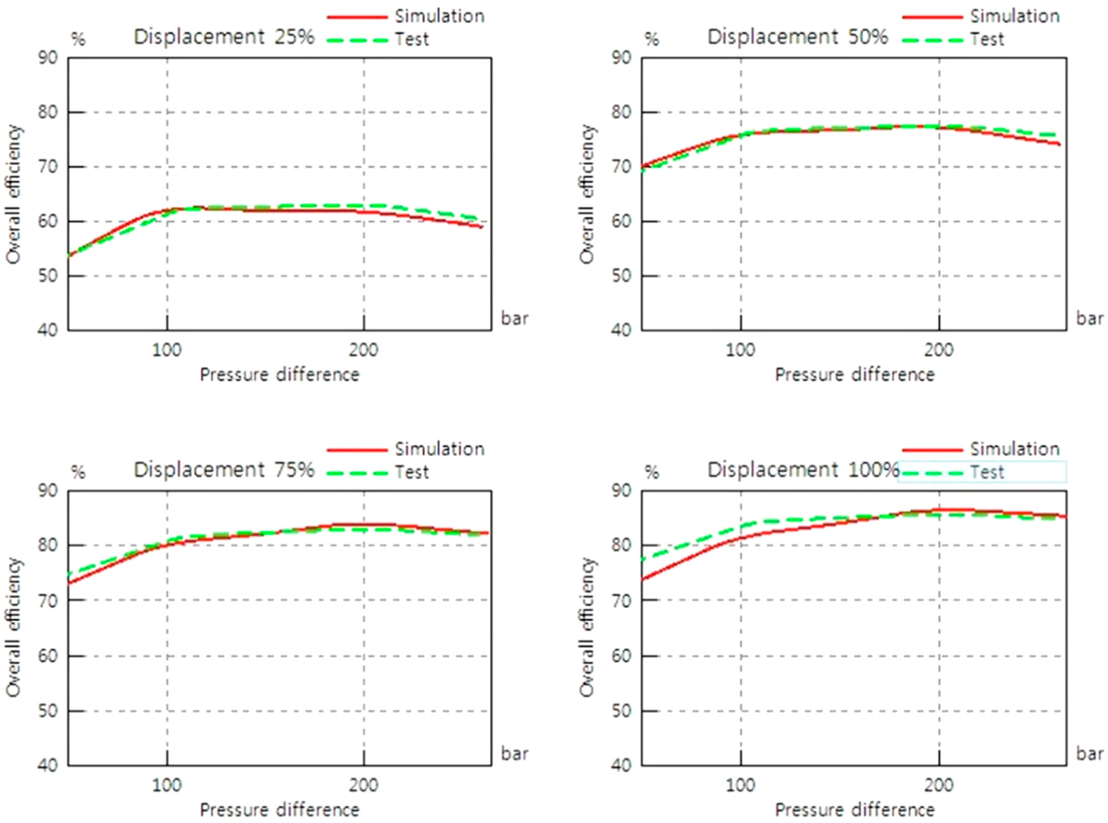
Figure 6.
Performance of the induction motor. (a) Torque map and (b) induction motor efficiency.

Figure 7.
Development of the wind turbine blade. (a) Simulation model and (b) torque map of the wind turbine blade.
Figure 7.
Development of the wind turbine blade. (a) Simulation model and (b) torque map of the wind turbine blade.

Figure 8.
Development of a simulation environment of the wind turbine generator: Step 1.
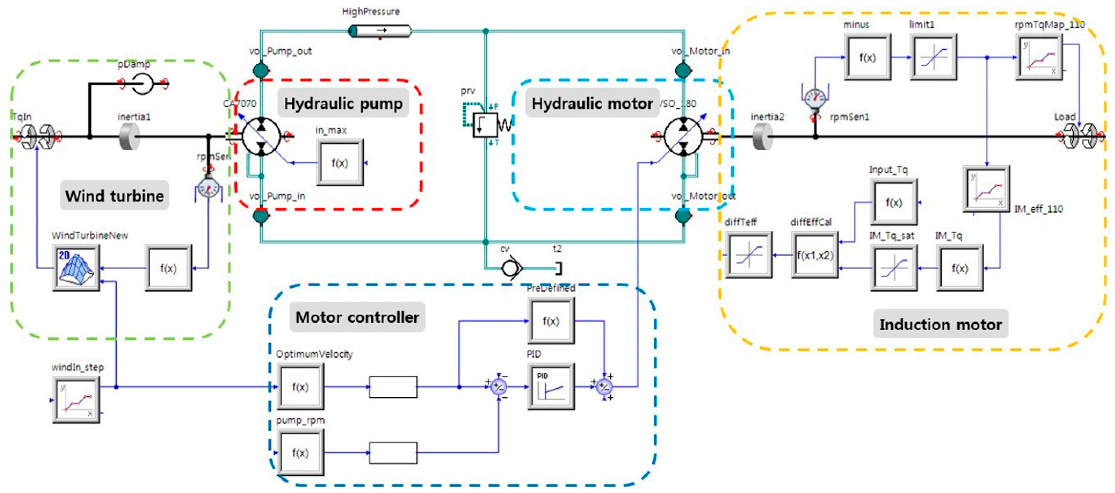
Figure 9.
Basic characteristics analysis results of step 5. (a) Turbine blade torque; (b) hydraulic pump; (c) induction motor power; and (d) step 5 overall efficiency.
Figure 9.
Basic characteristics analysis results of step 5. (a) Turbine blade torque; (b) hydraulic pump; (c) induction motor power; and (d) step 5 overall efficiency.

Figure 10.
Annual wind speed occurrence frequency in Muan, Jeollanam-do. (a) Occurrence days vs. wind speed and (b) occurrence rate vs. wind speed.
Figure 10.
Annual wind speed occurrence frequency in Muan, Jeollanam-do. (a) Occurrence days vs. wind speed and (b) occurrence rate vs. wind speed.

Figure 11.
System efficiency analysis results according to powertrain combination. (a) Torque map and (b) Generation efficiency.
Figure 11.
System efficiency analysis results according to powertrain combination. (a) Torque map and (b) Generation efficiency.

Figure 12.
System power generation according to powertrain combination. (a) Torque map and (b) generation efficiency.
Figure 12.
System power generation according to powertrain combination. (a) Torque map and (b) generation efficiency.

Table 1.
Wind turbine powertrain combination.
| No. | Pump1 | Pump2 | Motor1 | Motor2 | Induction Motor |
|---|---|---|---|---|---|
| 1 | 3771 cc/rev | 1256 cc/rev | 180 cc/rev | 40 cc/rev | 110 kW |
| 2 | 2512 cc/rev | 2512 cc/rev | 180 cc/rev | 71 cc/rev | 110 kW |
| 3 | 3771 cc/rev | 1256 cc/rev | 180 cc/rev | 40 cc/rev | 110 kW + 27 kW |
| 4 | 2512 cc/rev | 2512 cc/rev | 180 cc/rev | 71 cc/rev | 110 kW + 27 kW |
| 5 | 4400 cc/rev | - | 180 cc/rev | - | 110 kW |
© 2018 by the authors. Licensee MDPI, Basel, Switzerland. This article is an open access article distributed under the terms and conditions of the Creative Commons Attribution (CC BY) license (http://creativecommons.org/licenses/by/4.0/).
Share and Cite
MDPI and ACS Style
Kim, D.; Park, B.; Jang, J. Wind Turbine Generator Efficiency Based on Powertrain Combination and Annual Power Generation Prediction. Appl. Sci. 2018, 8, 858. https://doi.org/10.3390/app8060858
AMA Style
Kim D, Park B, Jang J. Wind Turbine Generator Efficiency Based on Powertrain Combination and Annual Power Generation Prediction. Applied Sciences. 2018; 8(6):858. https://doi.org/10.3390/app8060858
Chicago/Turabian StyleKim, Dongmyung, Byeongcheol Park, and Joosup Jang. 2018. "Wind Turbine Generator Efficiency Based on Powertrain Combination and Annual Power Generation Prediction" Applied Sciences 8, no. 6: 858. https://doi.org/10.3390/app8060858
Note that from the first issue of 2016, this journal uses article numbers instead of page numbers. See further details here.