Reliability-Based View Synthesis for Free Viewpoint Video

Faculty of Electronics and Information Engineering, Shenzhen Graduate School, Harbin Institute of Technology, Shenzhen 518055, China
*
Author to whom correspondence should be addressed.
Appl. Sci. 2018, 8(5), 823; https://doi.org/10.3390/app8050823
Submission received: 16 April 2018
/
Revised: 11 May 2018
/
Accepted: 16 May 2018
/
Published: 20 May 2018
Abstract
:Featured Application
View synthesis technology is important for free viewpoint video (FVV) and multiview video coding (MVC). It is a practical approach to reduce storage and transmission bandwidth for multiview videos.
Abstract
View synthesis is a crucial technique for free viewpoint video and multi-view video coding because of its capability to render an unlimited number of virtual viewpoints from adjacent captured texture images and corresponding depth maps. The accuracy of depth maps is very important to the rendering quality, since depth image–based rendering (DIBR) is the most widely used technology among synthesis algorithms. There are some issues due to the fact that stereo depth estimation is error-prone. In addition, filling occlusions is another challenge in producing desirable synthesized images. In this paper, we propose a reliability-based view synthesis framework. A depth refinement method is used to check the reliability of depth values and refine some of the unreliable pixels, and an adaptive background modeling algorithm is utilized to construct a background image aiming to fill the remaining empty regions after a proposed weighted blending process. Finally, the proposed approach is implemented and tested on test video sequences, and experimental results indicate objective and subjective improvements compared to previous view synthesis methods.
1. Introduction
In the past few decades, three-dimensional video has been widely adopted in various applications. Free viewpoint video (FVV) is a novel display format that has evolved from 3D video that enables viewers to watch a scene from any position [1]. This free navigation (FN) experience provides a rich and compelling immersive feeling that is much better than traditional 3D video [2]. However, FVV has significant requirements for video acquisition, compression, and transmission technology. Due to the limitations on camera volume and bandwidth of the communication system, only a limited number of views can be transferred. View synthesis technology is proposed to support the FN capability of generating texture images that are not captured by a real camera. Depth image-based rendering (DIBR) [3] is a crucial technology for view synthesis. DIBR utilizes one or more reference texture images and their associated depth images to synthesize virtual view images, wherein every pixel in the original reference image plane is projected to the 3D world coordinate system according to its associated depth value; thereafter the 3D world coordinates are projected onto the image plane in the virtual viewpoint [4].
Although virtual view from an arbitrary viewpoint can be reconstructed by utilizing reference texture and depth information, DIBR still brings some artifacts due to the inaccurate depth images. The geometric misalignment between foreground objects and background regions causes boundary noise and wrapping position displacement. The projected float results lead to rounding errors, which further cause pinholes, cracks, and blurs. In addition to these artifacts, a critical problem also arises during the generation of virtual images, since the regions covered by foreground objects in the reference views may be disoccluded in the virtual viewpoints, and these areas will appear as large holes in the virtual view, also referred to as disocclusions.
In this paper, we propose a novel synthesis framework using two reference viewpoints. This method first determines whether the pixel-wise depth map is reliable or unreliable, then refines some of those unreliable depth values. Second, an adaptive background modeling method is employed to construct background information, aiming to fill the remaining empty regions after a proposed weighted blending. In addition, the proposed adaptive median filter and depth map processing method (DMPM) show satisfactory performance on reduction of noise and other unwanted effects while the texture images remain sharp and clear. This improvement comes from their focus on processing the target pixels instead of handling every pixel in the intermediate texture images. The paper is organized as follows. The related classical algorithms are discussed in Section 2. In Section 3, the proposed framework is described in detail. The experimental results and conclusions are provided in Section 4 and Section 5, respectively.
2. Related Work
Depth image-based rendering is one of the most common methods of generating virtual viewpoints at arbitrary locations [3,5]. Hence the accuracy of the depth map is very important for the directly warped image quality. Meanwhile, the associated depth maps are coarse because of the deficient stereo matching algorithm or low-precision depth acquisition instrument, and synthesized images are not capable of satisfying the visual perception. Initially, the common approach to eliminate pinholes, cracks, and other artifacts was to preprocess the depth maps before DIBR, aiming to reduce the disparity along the boundary between foreground and background. In [6], Zhang and Tam used a symmetric Gaussian filter to smooth the whole depth map, and in [7] they used an asymmetric filter to reduce the vertical edge artifacts. In [8], Cheng used the background information to cover the holes after using a bilateral filter to preprocess the depth maps. In [9], an edge-dependent Gaussian filter, which is capable of smoothing the depth map while preserving the boundary along the foreground and background, was presented. Based on the experimental results and subjective performance outcome, all of the filters in [6,7,8,9] easily caused geometrically distorted foreground objects, especially when the distance between the reference view and virtual view was large, and the artifacts and other unwanted effects could be seen as unsatisfactory. In this paper, depth consistency cross-checking is used to check whether the depth value of each pixel is reliable or unreliable. For the left reference view, each pixel in the texture image is warped to the right reference viewpoint to verify its similarity to the corresponding depth map. A pixel is marked as unreliable if it fails to match the corresponding texture pixel in another reference view. The cross-checking for the right view is similar.
In the second period, there are two methods to solve large-hole region problems, spatial correlation and temporal correlation [5]. In the spatial domain, some methods utilize texture information in the neighboring regions of the frame that are selected at the same moment. Criminisi et al. [10] proposed an exemplar-based method that iteratively fills the disocclusions using the neighboring information; nowadays, this method denotes a classical inpainting algorithm. Experimental results show that inpainting obtains good performance when holes appear as narrow gaps, but the texture information is easily lost when holes are large. In fact, experiments indicate that large holes are always caused by disocclusions. In [11], Ahn and Kim presented a novel virtual view synthesis method with a single viewpoint plus depth (SVD) format, which can cover disoccluded regions in a visually plausible manner. This improved texture synthesis is realized by exemplar-based texture synthesis, including a new priority term and a new best exemplar selection based on both texture and depth information. Actually, these spatial methods always focus on filling the narrow gaps or small holes in the texture image, while texture synthesis can fill the large-scale holes [12,13,14]. Since large holes are observed when areas that are occluded by foreground objects in the reference view become exposed in the synthesized view, view-blending approaches can be used to alleviate this problem, as two adjacent cameras can cover a relatively wider viewing angle [15,16,17].
As to exploiting the temporal correlation, Scheming and Jiang [18] tried to determine the background information using a background subtraction method, but this approach relies on good performance of the foreground segmentation method, so it cannot be adopted in complex circumstances. Chen explored the motion vector of H.264/AVC bit stream to render disocclusions in the virtual view [19]. In [20,21], a background sprite was generated by the original texture and synthesized images from the temporal previous frames using disocclusion filling, but the temporal consistency of the synthesized images needs further investigation, as described in [22]. In [23], Yao proposed a disocclusion filling approach based on temporal correlation and depth information. Experimental results showed that this approach yields better subjective and objective performance beyond the above-mentioned spatial methods of filling disocclusions. However, the SVD format limits its wide usage because of the small baseline. Besides, some disocclusion regions that are not included in a single reference view may easily be spotted in another virtual viewpoint, and reverse mapping [4] may be more reliable. In [23], Luo and Zhu et al. proposed the use of a constructed background video with a modified Gaussian mixture model (GMM) to eliminate the holes in synthesized video. The foreground objects are detected and removed, then motion compensation and modified GMMs are applied to construct a stable background. Results indicated that a clean background without artifacts of foreground objects can be generated by using the proposed background model, so that the blurry effect or artifacts in disoccluded regions can be eliminated and the sharp edges along the foreground boundaries can be preserved with realistic appearance [24].
Although [17] indicates that large holes in a target virtual view can be greatly reduced by using other more neighboring complementary views in addition to the two (commonly used) most neighboring primary views, we still employ only two reference views to render virtual views in our proposed framework. The occlusions that appear on one warped image will be filled by another reference viewpoint in the weighted blending process.
In this paper, a multiview plus depth (MVD) format is employed for view synthesis. Two reference views are selected to interpolate virtual views located between them. Occlusions that appear on one warped image will be filled by another reference viewpoint. In addition, an adaptive background modeling method is proposed to construct background intensity distribution. The stable constructed reference background image helps to fill the remaining unfilled regions that are left due to the unreliable depth map. Another novelty of the proposed algorithm relates to depth refinement, which has the advantage of eliminating some noise caused by the coarse depth map. We also present a weighted blending process to blend two warped images from reference views based on the reliability of each pixel. An adaptive median filter and a depth map processing method are utilized before generating the synthesized virtual image.
3. Proposed Framework
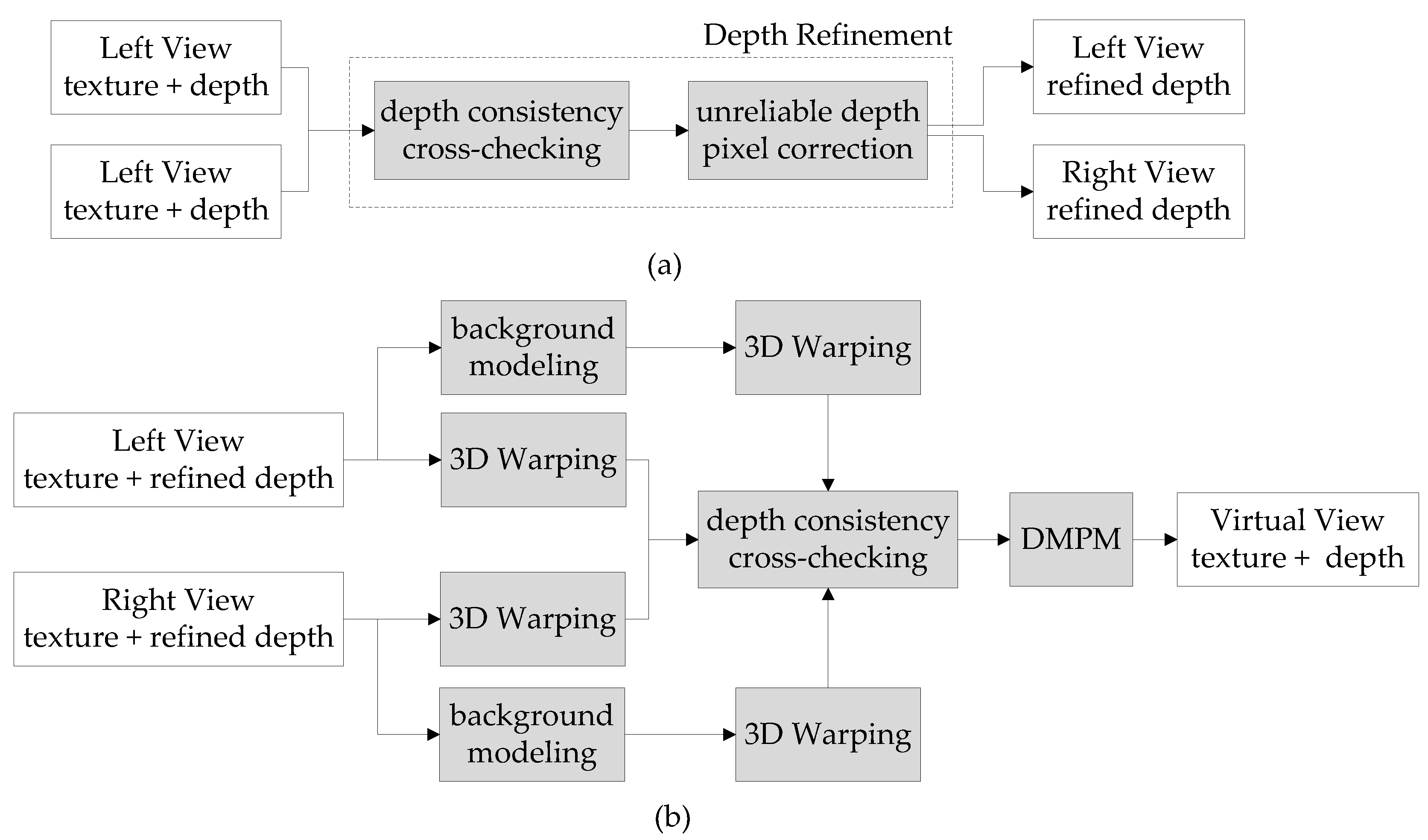
In this section, the proposed approach will be presented in detail. The framework of the proposed synthesis algorithm is illustrated in Figure 1. There are mainly four techniques proposed in this framework: depth refinement, background modeling, reliability-based blending, and depth map processing method. These approaches will be discussed in Section 3.
3.1. Depth Refinement
There are two steps in the depth refinement process, as illustrated in Figure 1a. In the first step, depth consistency cross-checking is used to check whether each pixel’s depth value is reliable or unreliable. Second, depth refinement is employed to interpolate the depth values of unreliable pixels. The details of the first step are as follows. For depth consistency cross-checking of the left reference view: let (u, v) be the coordinate of one pixel from the left reference view, then its corresponding pixel (uw, vw) in the right reference view is obtained through the classical DIBR technology [2]. The texture value I and depth value D of these two pixels are verified; the subscript L and R indicate left view and right view, respectively. Ith is a large preset threshold value for texture comparison and Dth is a small preset threshold value for depth comparison. The consistency checking produces five results, as follows:
- (1)
- If and are both satisfied, this implies that these two pixels are matched. This depth pixel in the left reference depth map is reliable only in this situation, and it is marked as black in its cross-checking mask.
- (2)
- If and are both satisfied, this implies that these two pixels fail to match. In this situation, there is a high probability that the pixel belongs to the occlusion area and the depth pixel in the left reference depth map fails to check whether it is reliable or not, then it is marked as blue in its cross-checking mask.
- (3)
- If and are both satisfied, this implies that these two pixels fail to match. Either an erroneous texture pixel or an unreliable depth value causes this situation. We will check its surrounding depth distribution to find the real reason in the second step. The depth pixel in the left reference depth map is unreliable and it is marked as red in its cross-checking mask.
- (4)
- If and are both satisfied, this also implies that the depth pixel is unreliable, and it is marked as green in its cross-checking mask.
- (5)
- Some pixels in the left reference view are not able to project into the right reference view, because their corresponding pixels are located outside the image boundary. These areas are marked as white.
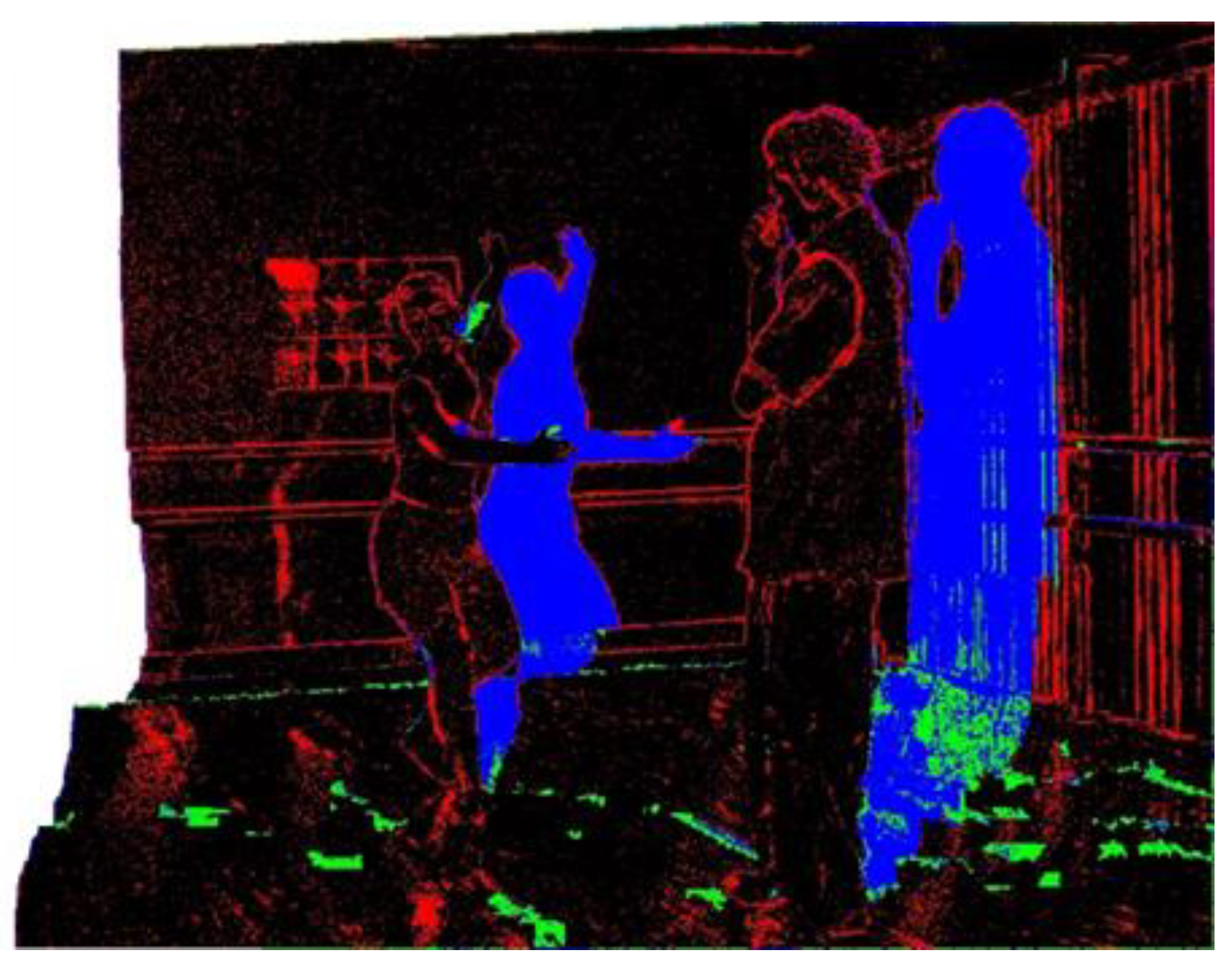
Figure 2 shows a result of the depth consistency check; because pixels in the white and blue regions fail to get a chance to verify their reliability, they are all determined to be unreliable and a specific weight is given when they are interpolated into virtual view. Several measures are implemented to refine other unreliable pixels, especially for the red and green regions. The main idea for the refinement is to find the most appropriate reliable pixel value to interpolate the depth value of unreliable pixels. Neighboring pixels from four directions are utilized here, and both the inverse proportion of distance and the reliability of the depth value are considered in calculating the weighting factors. If the reliable depth pixel maps to a reliable pixel in the other view, this indicates that this depth pixel is highly reliable. On the contrary, if the corresponding pixel in the other view is unreliable, the reliability of the pixel is lower.
Let WDt, WDb, WDl, and WDr be the weighting factors calculated by the distance from the current unreliable depth value to the nearest reliable depth pixel in top, bottom, left, and right directions, respectively. WH and WL are the weighting values with high reliability and low reliability, respectively. The weighting factor for each direction can be formulated as:
where the subscript direction can be either t, b, l, or r. The four weighting factors are normalized as WNdirection, then the unreliable depth value Dr can be interpolated by Equation (2):
where Dd is the nearest reliable depth value in one of four directions.
3.2. Adaptive Background Modeling
In the previous step, a refined depth map was obtained. In Section 3.2, we propose to apply an adaptive background modeling method evolving from Gaussian mixture model (GMM) to generate a reference image. GMM is commonly used in video processing to detect moving objects because of its capacity to identify foreground and background pixels [7]. In previous research, GMM was utilized to construct a stable background image aiming to fill large empty regions. However, GMM is not suitable for scenes that contain periodic or reciprocating foreground objects; these foreground moving objects are easily detected as erroneous background pixels, thus generating an inaccurate background image. In addition, some background pixels might have slight changes, for example, pixel densities are different while shadows caused by foreground objects appear or move. Thus, the stable background images generated by previous approaches always had blurring effects and were not accurate. In our proposed adaptive background modeling method, both the texture images and their associated depth maps are utilized to explore the temporal correlation. In addition, we propose to apply a reliability-based view synthesis method using background information to interpolate the intermediate image and fill the disocclusions.
The proposed method works at the pixel level, and every pixel is modeled independently by a mixture of K Gaussian distributions, where K is usually between 3 and 5. By using this distribution, pixel values that have a high probability of occurring are saved if their associated depth values show they belong to the background. The Gaussian mixture distribution with K components can be written as [25]:
where denotes the probable density of value of pixel j at time t; η is the Gaussian density function with three dependent variables: , , and , where denotes the mean value of pixel ; and is the variance value of the pixel. Further, is the weight of the ith Gaussian distribution at time t of pixel j, with . The function η is given by:
Before texture information is modeled by Gaussian distribution, we propose to verify each novel pixel to ensure that it is not from a foreground region. If the depth value is much bigger than the stored depth buffer (which means this pixel is nearer to a captured device), the pixel is considered as a foreground pixel. Otherwise, if the depth value is much smaller than the stored buffer, the pixel is considered as a background pixel, and the modeled distribution is not reliable and should be restarted. The detailed process to generate the reference background distribution is as follows:
- Initialization. The model is initialized at the beginning of the generation (time t0):where the variance value is set to a certain large number, is the stored depth buffer for pixel j, and is the depth value of pixel j at time .
- Update. In the next frame, i.e., at time , we first check the depth level of this pixel, and is compared with the existing depth buffer . There are three situations for the depth comparison results:
- (a)
- If the condition is satisfied ( is a predefined threshold depth value), this indicates that the new pixel belongs to the foreground objects, it will be discarded, and background distribution will not be updated.
- (b)
- If is verified, is searched to match with K Gaussian models. From each model i from 1 to K, if the condition is satisfied, the matching process will stop, and the matched Gaussian model will be updated as follows:where α is the model learning rate (α = 0.01), and . The other parameters of the Gaussian models remain unchanged except:These two parameters reflect the rate of model convergence. If pixel fails to match all the current Gaussian models, a new Gaussian model is introduced to evict the Gaussian model with the smallestvalue. The mean and variance values of the other Gaussian models remain unchanged, while the new model is set with , , . Finally, the weights of K Gaussian models are normalized to .
- (c)
- In the third situation, if the condition is satisfied, this indicates that the new input pixel belongs to the background and the previous Gaussian distributions need to be abandoned. The first step is executed for.
- Convergence. The remaining frames are processed by repeating step 2. The value of background pixels is derived by μ, and the most stable pixels in the time domain are modeled as background image; meanwhile, the number of Gaussian models of each pixel is obtained to determine whether the pixel experiences similar intensities over time or not.
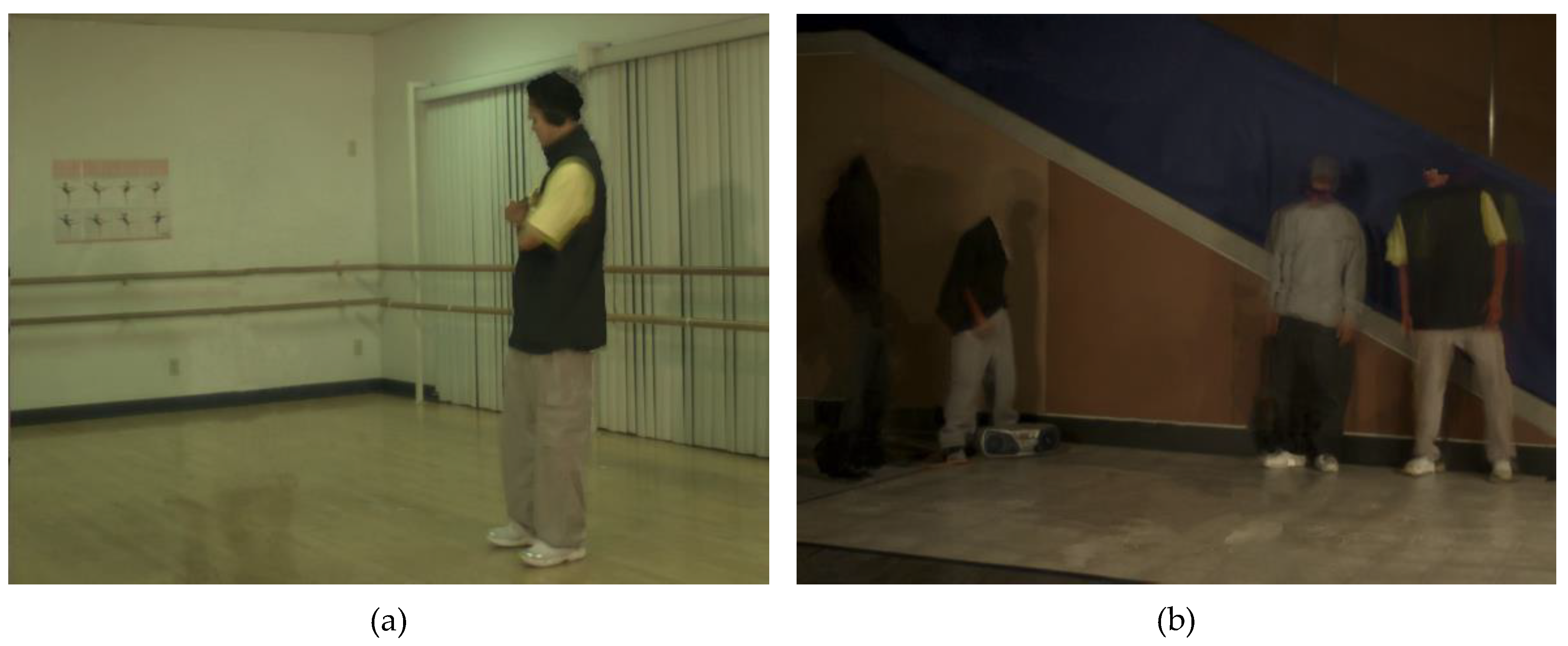
Figure 3 shows two examples of adaptive background modeling. Figure 3a presents the Ballet background image generated with a small baseline, where cam03 is chosen as a target virtual viewpoint that is interpolated by the reference viewpoints cam02 and cam04. Figure 3b presents the Breakdancers modeling result, where the background image at virtual viewpoint cam04 is projected from reference viewpoints cam02 and cam06. Although some foreground objects are stored in a stable temporal background reference using the mechanism of the proposed framework, these effects would not affect the quality of the final synthesized image, since the filling of remaining empty regions always occurs in the background areas. Thus, the temporal stable background information can be obtained by both large and small baseline instances. This adaptive background modeling approach can be widely adopted in applications with unchanged scenes.
3.3. Reliability-Based Weighted Blending
As the background distribution for each reference view is obtained by the proposed background modeling method discussed in Section 3.2, two background images are projected into virtual viewpoint and then blended into one background image in virtual viewpoint (represented by IB). Previous research shows that GMM has an inherent capacity to capture background and foreground pixel intensities; missing pixel intensities of an occluded area are successfully recovered by exploiting temporal correlation.
In our proposed method, weighting factors are also applied to blend two reference views and one background image into a synthesized image. Two reference texture images are projected to virtual view using their corresponding refined depth maps, and two intermediate texture images IL, IR and depth images DL, DR are obtained. The reliability-based weighted blending process to produce a virtual image IV is as follows:
- (1)
- If a pixel is filled in both IL and IR, first two depth values are compared. If the depth value of one pixel is much bigger than the other, this indicates that one pixel is obviously nearer to the capturing device. IV is filled by the pixel with a bigger associated depth value. If two depth values are very close, weighting factors are utilized. IV is formulated as follows:where WD is the weighting factor for the inversely proportional distance between reference view and virtual view, and WR is the weighting factor for the previously defined reliability of depth value. One of three values (rH, rM, or rL) is assigned to WR when a pixel in this reference intermediate image is mapped by a reliable, refined, or unreliable depth value, respectively. It should be noted that WL and WR need to be normalized by so that .
- (2)
- If only one pixel is filled in two reference views, for example only IL is filled, the reliability of IL is taken into consideration. If IL is mapped by a reliable depth value, IV can simply be filled with IL (). Otherwise, background information is used to generate IV. If DL is close to the background depth value, then ; if DL is much bigger than DB, .
- (3)
- If pixels in both reference views are not filled, we use the constructed background image to deal with the hole-filling challenge. First, we check the surrounding depth value of IV and find the filled depth value to determine a proper depth value range. Then IV is filled by the background pixel if its depth value is in the obtained range. Otherwise, inverse warping and classical inpainting are applied to fill IV.
We propose this hole-filling method to ensure that background pixels are appropriate to fill the remaining hole regions. Because they adopt depth information, background pixels can be chosen to improve the rendered image quality even when the hole is surrounded by foreground objects.
3.4. Depth Map Processing Method
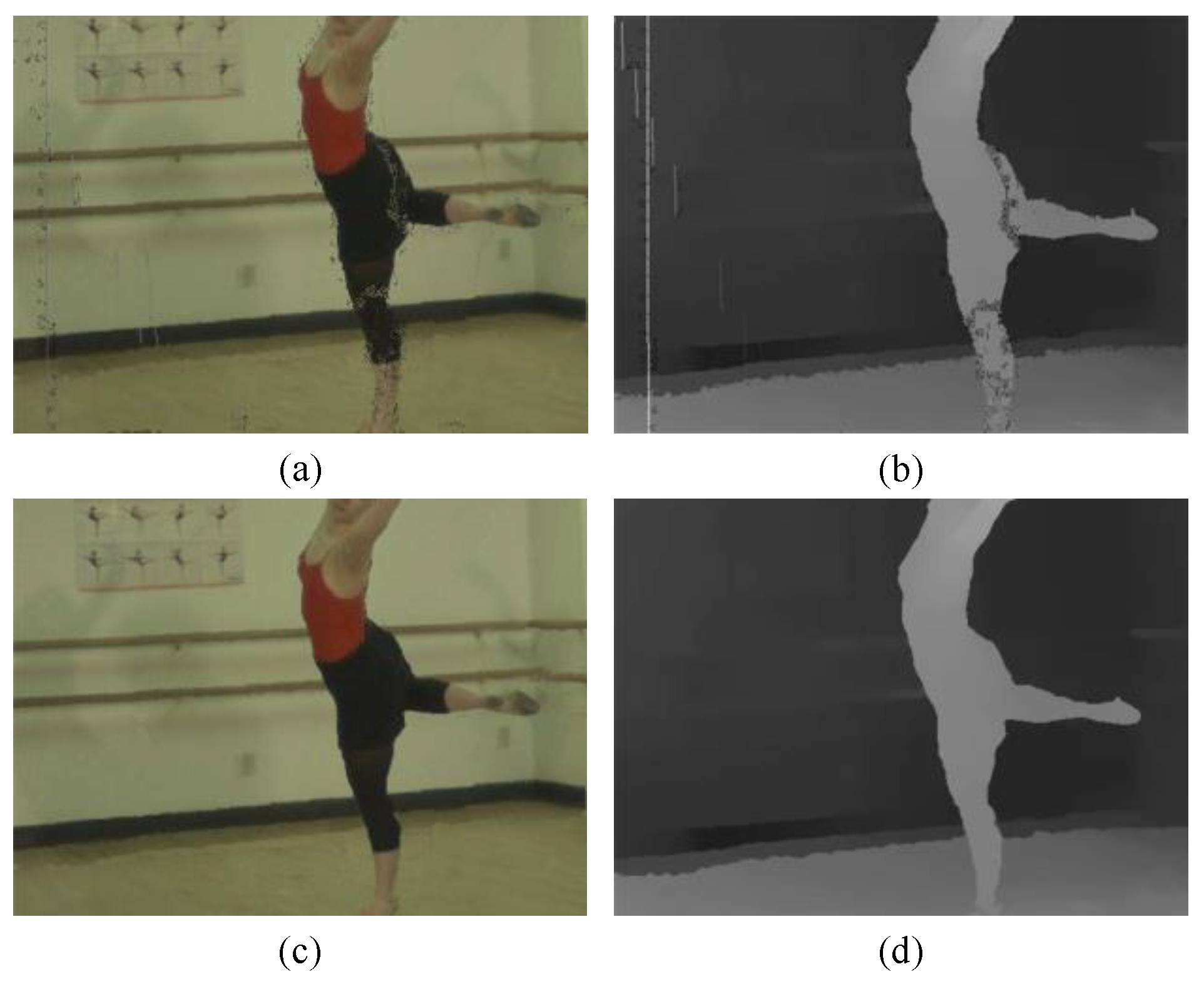
After weighted blending is completed, the warped texture image and depth map become entirely filled. However, in the previous process, cracks and pinholes could be observed in the rendered image. With the previous method, a classical median filter was applied to smooth the texture image or remove these artifacts. In our framework, a depth map processing method is proposed. Not only the above-mentioned artifacts, but also the background pixels in cracks of foreground regions (shown in Figure 4a,b) can be removed. This method has advantages in preserving the texture details, since it is only performed on the detected coordinates.
The main idea of DMPM is based on the fact that pixel value in depth maps always changes smoothly in a large area, except in the case of sharp edges in the boundary area between foreground objects and background. These features allow easy detection of noise in depth maps. In fact, most artifacts and noise caused by inaccurate depth values are reduced because of the previously introduced depth refinement, but some unreliable or undetected depth values remain in the reference depth map, most of them in out-of-boundary areas and occluded areas. Therefore, DMPM is still necessary. Details of the depth map processing method are as follows:
- (1)
- A conventional median filter is proposed to apply to the coarse depth map to obtain an improved depth map . It is capable of removing the existing noise and preserves the sharp boundary information.
- (2)
- The texture image is refined according to the improvement of its associated depth map. If the condition is satisfied ( is a threshold value for depth difference), this indicates that the depth value of the pixel is unreliable and it is renewed after the median filter. An inverse mapping process using the updated depth value is employed to find an appropriate texture pixel. A depth range is used as a candidate to find its corresponding pixel in two reference views. In Equations (11) and (12), we can get a corresponding reference pixel location (ur, vr) through pixel (x, y) and the associated depth values zv and zr; A and b denote rotation matrix and translation matrix, respectively. Several measurements are used to make sure a highly reliable pixel is obtained by using backward warping. First, the depth value of the obtained pixel should be close to the updated depth value . Second, the disparity between (x, y) and (ur, vr) should not be too large according to the alignment of the reference viewpoint and virtual viewpoint:
In our previous method, we simply used a median filter on (x, y), and this turned out to be very effective when the texture of this area was smooth. However, a median filter easily produces blurring effects when the scene has detailed textures. Unlike the texture images, the smooth regions in the depth map are invulnerable to the filter with gray value distributions. After the renovation is conducted, the associated texture image is updated according to the improvement of its depth map. Figure 4d shows the updated version of the integrated depth map, where the infiltration errors and unnatural depth distribution are eliminated by the classical median filter, while the sharp edges are preserved. Comparing Figure 4a,c, the DMPM generates desirable improvement and avoids filtering of the entire image at the same time.
4. Experimental Results
In this section, the proposed framework is implemented in C++ based on OpenCV, and the tested multiview video plus depth sequences include two Microsoft datasets: Ballet and Breakdancers. In all video sequences, the size of each frame is 1024 × 768 pixels, and each video contains 100 frames with an unmoved background. The baseline between two adjacent cameras is 20 cm for both Ballet and Breakdancers. The associated depth maps and camera parameters are provided with the sequences. The format of all video sequences is avi, while texture images contain three channels (RGB).
To evaluate the performance of the proposed method, we implemented two state-of-the-art methods and my previous work in [26], in order to compare this with the proposed approach. One of these two methods is a commonly used reference software, VSRS 3.5 [27], which mainly contains a simple DIBR method [3] and a classical inpainting technique [10]. The other is a hole-filling method exploiting temporal correlations based on GMM [5]. These two methods [5,27] represent the exploitation of spatial correlation and temporal correlation, respectively. In each experiment, the test sequence was composed of three real video sequences from three reference viewpoints. The coded left and right views with their associated depth videos were projected to interpolate the virtual video in the target viewpoint between them. The rendered sequence was compared with the actual video on the target viewpoints to measure the peak signal-noise ratio (PSNR) and structural similarity index (SSIM). In order to show wide practical applicability of the proposed synthesis algorithm, each view synthesis method was performed on both small baseline and large baseline instances. Table 1 and Table 2 show the average PSNR and SSIM values for 100 frames.
In the PSNR evaluation, the proposed approach obtained 4–10 dB better results than VSRS 3.5 on Ballet for a large baseline instance. In the case of a small baseline, the results for both Ballet and Breakdancers were also better. The proposed method also showed better results beyond GMM-based disocclusion filling method and my previous work. Inpainting is an effective algorithm to fill narrow gaps and other small empty regions when the baseline is small, however, it is not practical for fill large empty regions. Moreover, my previous work did not perform well for both Ballet and Breakdancers sequences. This is due to the fact that simple GMM is not capable to deal with the scenes which foreground objects are with reciprocating motion.
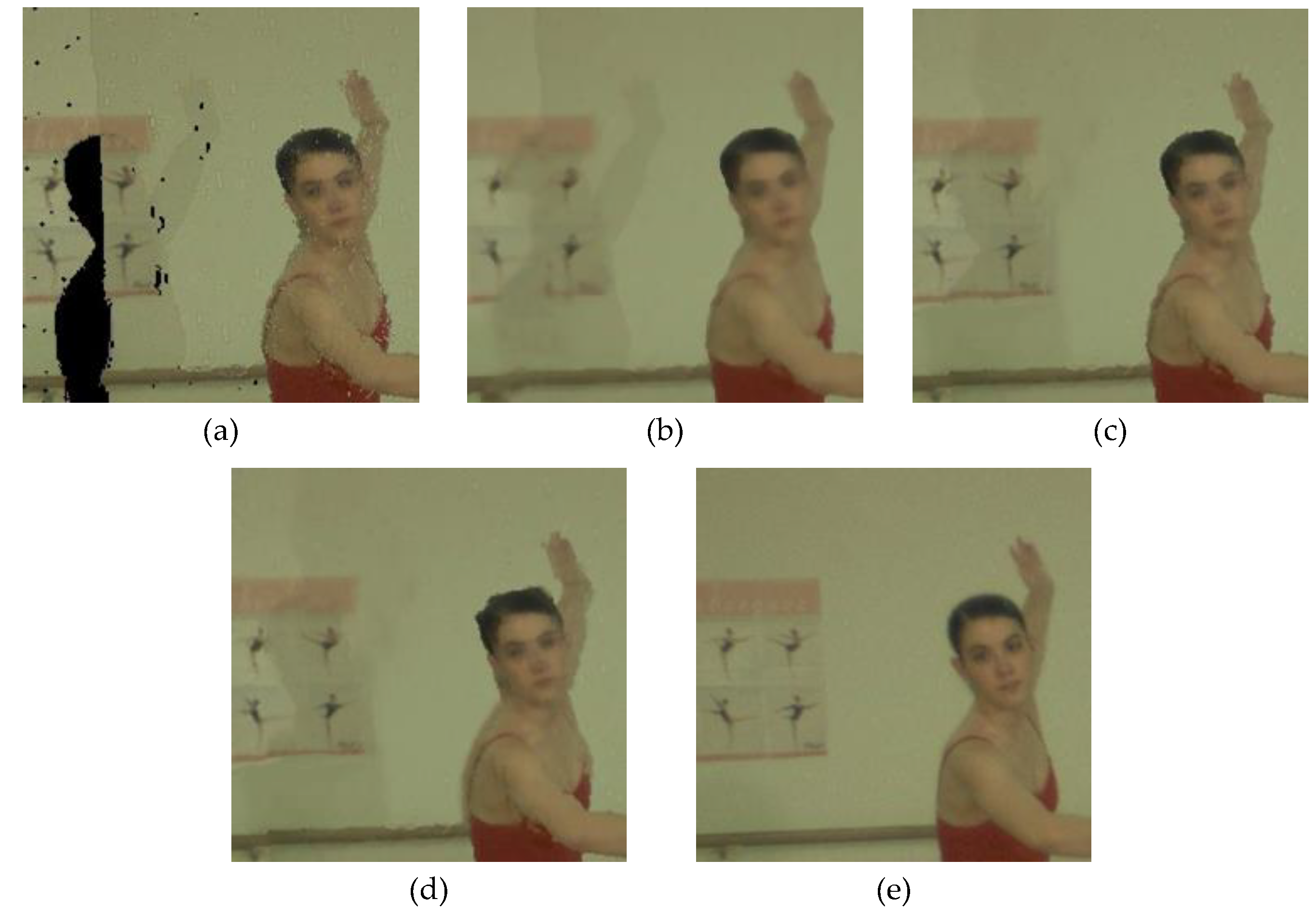
Consequently, the proposed approach yielded better results on both tested sequences. The larger the baseline, the better the results. In addition to the objective measurements, Figure 5 shows a subjective comparison. Figure 5a presents the synthesized results generated by a simple DIBR technology, where the disocclusion regions and pinholes remain to be filled. Figure 5b shows the performance of VSRS 3.5, where large empty regions are filled based on neighboring texture information. Blurring effects are observed, in contrast to our proposed method in Figure 5e. This improvement comes from our idea of avoiding global processing for every pixel to handle the noise. Hence, our method shows desirable results in reducing errors and removing unwanted effects, while texture remains sharp and clear. Figure 5c shows an enlarged part of the synthesis result produced by the GMM-based disocclusion filling method; the temporal correlation method shows better performance in filling large empty areas beyond the inpainting method. Depth refinement and weighted blending lead to much more satisfactory interpolation results, as shown in Figure 5e.
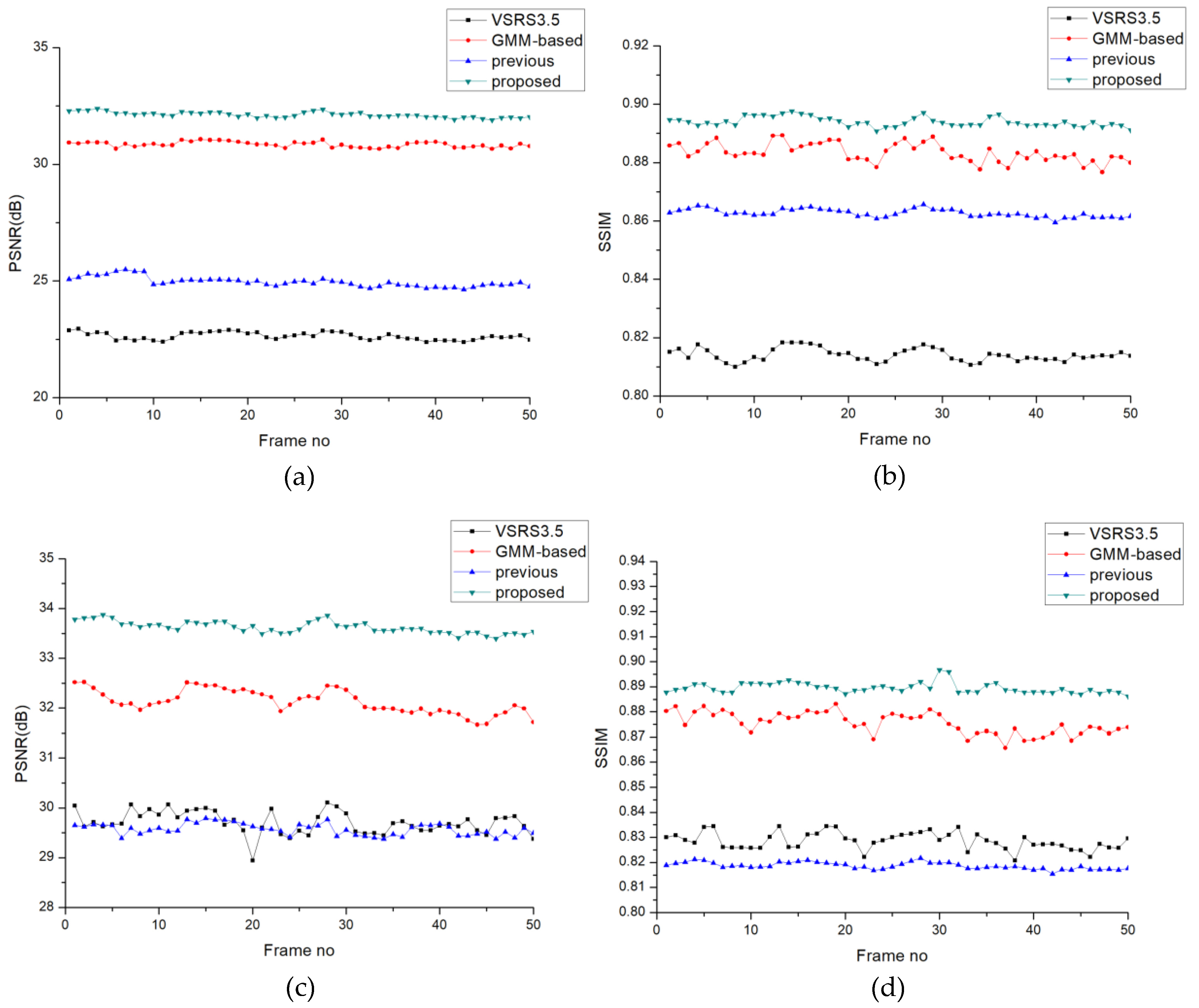
Frame-by-frame comparisons of PSNR and SSIM are shown in Figure 6. Figure 6a,b show a synthesis result with a large baseline: viewpoint cam03 is interpolated by cam01 and cam 07. Another PSNR and SSIM comparison (Figure 6c,d) comes from a small baseline; two reference viewpoints, cam03 and cam05, were utilized to render target virtual view cam04. Both instances are from the sequence Ballet. Obviously, exploring temporal correlations to fill the disocclusions yields better performance beyond the inpainting-based view synthesis method, which only explores the spatial correlation, especially when the baseline is large. In all the frames, our proposed framework shows more stable output than the GMM-based method.
In this article, we additionally tested the computation time for all the four approaches. Greater improvements in subjective and objective image quality are brought by much more complex computation. In our proposed method, 3D warping process is performed six times and adaptive background modeling is applied twice, that is the reason why the computation cost of my proposed method is high. The first reason is that the GPU-accelerated algorithm is commonly used for image processing and the hardware performance is growing rapidly, the increased computation time for one frame will not increase too much time for synthesizing the whole sequence if parallel algorithm is adopted. The second reason is that due to the mechanism of our proposed approach, we mainly explore the contribution of depth refinement technique and adaptive background modeling, the time can be shortened if this method is applied in practical applications. After all, our proposed method is implemented using OpenCV library, the computation time is capable to reduce a lot if we carefully using coding skills.
5. Conclusions
In this paper, we present a reliability-based view synthesis framework using depth refinement and an adaptive background modeling method. Multiple viewpoints are employed to render desirable virtual images. In the proposed algorithm, the disocclusion regions are filled by a combination of two sources. The first one comes from two reference viewpoints; the disocclusion regions generated from one reference view are more likely to be found from another reference view due to different position and viewing angle. If the disocclusion regions are lost in both reference views, the updated background image is utilized to fill the static regions. Experimental results indicate that depth refinement obviously improves the accuracy of the depth map, thus improving the performance of the proposed adaptive background modeling and forward (and backward) warping. In addition, an adaptive median filter and DMPM are proposed to replace the classical median filter due to their ability to eliminate unwanted effects and noise while ensuring high-quality texture images. The experimental results show that the combination of proposed techniques yields satisfactory subjective and objective improvement. There are three aspects to focus on in our future research. First, we will focus on improving synthesis quality while reducing computing complexity. Second, we will explore how to construct a stable temporal correlation for complex scenes with moving cameras. Finally, as deep learning is becoming more popular in various types of research, deep view synthesis seems to have a bright future.
Author Contributions
Z.D. and M.W. designed the experiments. Z.D. performed the experiments. Z.D. wrote the paper and analyzed the data. M.W. contributed simulation tools. M.W. supervise the whole work.
Funding
This research was funded by Shenzhen fundamental research project under Grant JCYJ20170412151226061 and Shenzhen fundamental research project under Grant JCYJ20170808110410773.
Acknowledgments
The authors would like to thank the Interactive Visual Media group at Microsoft Research for providing the video sequences Ballet and Breakdancers. This research is funded by Shenzhen fundamental research project (Grant JCYJ20170412151226061 and Grant JCYJ20170808110410773).
Conflicts of Interest
The authors declare no conflict of interest.
References
- Tech, G.; Chen, Y.; Müller, K.; Ohm, J.-R.; Vetro, A.; Wang, Y.-K. Overview of the multi-view and 3D extensions of high efficiency video coding. IEEE Trans. Circuits Syst. Video Technol. 2016, 26, 35–49. [Google Scholar] [CrossRef]
- Tanimoto, M.; Tehrani, M.P; Fujii, T.; Yendo, T. Free-viewpoint TV. IEEE Signal Process. Mag. 2011, 28, 67–76. [Google Scholar] [CrossRef]
- Fehn, C. Depth-image-based rendering (DIBR), compression, and transmission for a new approach on 3D-Tv. In Proceedings of the Society of Photo-Optical Instrumentation Engineers (SPIE), San Jose, CA, USA, 19–22 January 2004. [Google Scholar]
- Farid, M.S.; Lucenteforte, M.; Grangetto, M. Depth image based rendering with inverse mapping. In Proceedings of the IEEE 15th International Conference on Workshop Multimedia Signal Processing, Pula, Italy, 30 September–2 October 2013. [Google Scholar]
- Rahaman, D.M.M.; Paul, M. Virtual View Synthesis for Free Viewpoint Video and Multiview Video Compression using Gaussian Mixture Modeling. IEEE Trans Image Process. 2018, 27, 1190–1201. [Google Scholar] [CrossRef] [PubMed]
- Zhang, L.; Tam, W.J.; Wang, D.M. Stereoscopic image generation based on depth images. In Proceedings of the International Conference on Image Processing (ICIP), Singapore, Singapore, 24–27 October 2004; pp. 2993–2996. [Google Scholar]
- Zhang, L.; Tam, W.J. Stereoscopic image generation based on depth images for 3D TV. IEEE Trans. Broadcast. 2005, 51, 191–199. [Google Scholar] [CrossRef]
- Cheng, C.M.; Lin, S.J.; Lai, S.H.; Yang, J.C. Improved novel view synthesis from depth image with large baseline. In Proceedings of the 19th International Conference on Pattern Recognition (ICPR), Tampa, FL, USA, 8–11 December 2008; pp. 1–4. [Google Scholar]
- Lee, P.J. Non-geometric distortion smoothing approach for depth map preprocessing. IEEE Trans. Multimed. 2011, 13, 246–254. [Google Scholar] [CrossRef]
- Criminisi, A.; Perez, P.; Toyama, K. Region filling and object removal by exemplar-based image inpainting. IEEE Trans. Image Process. 2004, 13, 1200–1212. [Google Scholar] [CrossRef] [PubMed]
- Ahn, I.; Kim, C. A novel depth-based virtual view synthesis method for free viewpoint video. IEEE Trans. Broadcast. 2013, 59, 614–626. [Google Scholar] [CrossRef]
- Zhao, Y.; Zhu, C.; Chen, Z. Boundary artifact reduction in view synthesis of 3D video: From perspective of texture depth alignment. IEEE Trans. Broadcast. 2011, 57, 510–522. [Google Scholar] [CrossRef]
- Bertalmio, M.; Bertozzi, A.L.; Sapiro, G. Navier-stokes, fluid dynamics, and image and video inpainting. In Proceedings of the 2001 IEEE Computer Society Conference on Computer Vision and Pattern Recognition (CVPR), Kauai, HI, USA, 8–14 December 2001; pp. 355–362. [Google Scholar]
- Bertalmio, M. Strong-continuation, contrast-invariant inpainting with a third-order optimal PDE. IEEE Trans. Image Process. 2006, 15, 1934–1938. [Google Scholar] [CrossRef] [PubMed]
- Rahaman, D.M.M.; Paul, M. Hole-filling for single-view plus depth based rendering with temporal texture synthesis. In Proceedings of the IEEE International Conference on Workshop Multimedia Expo Workshops (ICMEW), Seattle, WA, USA, 11–15 July 2016; pp. 1–6. [Google Scholar]
- Rahaman, D.M.M.; Paul, M. Free view-point video synthesis using Gaussian mixture modeling. In Proceedings of the IEEE Conference on Image and Vision Computing, Auckland, New Zealand, 23–24 November 2015; pp. 1–6. [Google Scholar]
- Li, S.; Zhu, C.; Sun, M.T. Hole Filling with Multiple Reference Views in DIBR View Synthesis. IEEE Trans. Multimed. 2018. [Google Scholar] [CrossRef]
- Schmeing, M.; Jiang, X. Depth image based rendering: A faithful approach for the disocclusion problem. In Proceedings of the 3DTV-Conference: The True Vision—Capture, Transmission and Display of 3D Video, Tampere, Finland, 7–9 June 2010; pp. 1–4. [Google Scholar]
- Chen, K.Y.; Tsung, P.K.; Lin, P.C.; Yang, H.J.; Chen, L.G. Hybrid motion/depth-oriented inpainting for virtual view synthesis in multiview applications. In Proceedings of the 3DTV-Conference: The True Vision—Capture, Transmission and Display of 3D Video, Tampere, Finland, 7–9 June 2010; pp. 1–4. [Google Scholar]
- Köppel, M.; Ndjiki-Nya, P.; Doshkov, D.; Lakshman, H.; Merkle, P.; Müller, K.; Wiegand, T. Temporally consistent handling of disocclusions with texture synthesis for depth-image-based rendering. In Proceedings of the IEEE International Conference on Image Processing, Hong Kong, China, 26–29 September 2010; pp. 1809–1812. [Google Scholar]
- Ndjiki-Nya, P.; Koppel, M.; Doshkov, D.; Lakshman, H.; Merkle, P.; Muller, K.; Wiegand, T. Depth image-based rendering with advanced texture synthesis for 3-D video. IEEE Trans. Multimed. 2011, 13, 453–465. [Google Scholar] [CrossRef]
- Bosc, E.; Köppel, M.; Pépion, R.; Pressigout, M.; Morin, L.; Ndjiki-Nya, P.; Le Callet, P. Can 3D synthesized views be reliably assessed through usual subjective and objective evaluation protocols? In Proceedings of the 18th IEEE International Conference on Image Processing, Brussels, Belgium, 11–14 September 2011; pp. 2597–2600. [Google Scholar]
- Yao, C.; Tillo, T.; Zhao, Y.; Xiao, J.; Bai, H.; Lin, C. Depth map driven hole filling algorithm exploiting temporal correlation information. IEEE Trans. Broadcast. 2014, 60, 394–404. [Google Scholar] [CrossRef]
- Luo, G.; Zhu, Y.; Li, Z.; Zhang, L. A hole filling approach based on background reconstruction for view synthesis in 3D video. In Proceedings of the IEEE Conference on Computer Vision and Pattern Recognition (CVPR), Las Vegas, NV, USA, 27–10 Jun 2016; pp. 1781–1789. [Google Scholar]
- Stauffer, C.; Grimson, W.E.L. Adaptive background mixture models for real-time tracking. In Proceedings of the IEEE Conference on Computer Vision and Pattern Recognition (CVPR), Fort Collins, CO, USA, 23–25 June 1999; pp. 246–252. [Google Scholar]
- Deng, Z.M.; Wang, M.J. Hybrid Temporal Correlation Based on Gaussian Mixture Model Framework for View Synthesis. In Proceedings of the 18th International Conference on Computers and Communication Networks, Boston, MA, USA, 24–25 April 2017; pp. 1936–1944. [Google Scholar]
- Tanimoto, M.; Fujii, T.; Suzuki, K. Reference Software of Depth Estimation and View Synthesis for FTV/3DV. ISO/IEC JTC1/SC29/WG11, M15836. 2008. Available online: http://wg11.sc29.org/svn/repos/MPEG-4/test/trunk/3D/view_synthesis/VSRS (accessed on 19 May 2018).
Figure 1.
Framework of the proposed view synthesis: (a) illustration of Depth Refinement; (b) the framework of proposed approaches using refined depth information.
Figure 1.
Framework of the proposed view synthesis: (a) illustration of Depth Refinement; (b) the framework of proposed approaches using refined depth information.

Figure 2.
Result of depth consistency cross-check.

Figure 3.
Adaptive background modeling results: (a) Ballet background image; (b) Breakdancers background image.
Figure 3.
Adaptive background modeling results: (a) Ballet background image; (b) Breakdancers background image.

Figure 4.
Examples of depth map processing method: (a,b) enlarged integrated texture image and its associated depth map before depth map processing method (DMPM); (c,d) image and its associated depth map after DMPM.
Figure 4.
Examples of depth map processing method: (a,b) enlarged integrated texture image and its associated depth map before depth map processing method (DMPM); (c,d) image and its associated depth map after DMPM.

Figure 5.
Subjective comparisons of four disocclusion-filling methods for the sequence Ballet (frame 1): (a) disocclusions after simple depth image–based rendering (DIBR) [3]; (b) VSRS 3.5 [27]; (c) Modified Gaussian mixture model (GMM) method [5]; (d) previous method [26]; (e) proposed synthesis method.

Figure 6.
Frame-by-frame objective comparisons of PSNR and SSIM.


Table 1.
Average peak signal-noise ratio (PSNR) comparison of the proposed technique and three state-of-the-art techniques.
Table 1.
Average peak signal-noise ratio (PSNR) comparison of the proposed technique and three state-of-the-art techniques.
| Sequence | Camera Set | Baseline (cm) | PSNR (dB) | |||
|---|---|---|---|---|---|---|
| VSRS [26] | GMM-Based [5] | Previous [27] | Proposed | |||
| Ballet | 3, 5 → 4 | 20, 20 | 29.39 | 32.29 | 28.97 | 33.56 |
| 1, 7 → 3 | 40, 80 | 22.64 | 31.01 | 25.23 | 32.43 | |
| 1, 7 → 4 | 60, 60 | 22.03 | 31.13 | 25.78 | 32.54 | |
| 1, 7 → 5 | 80, 40 | 22.12 | 30.98 | 25.12 | 32.32 | |
| Breakdancers | 1, 3 → 2 | 20, 20 | 30.88 | 34.42 | 29.46 | 35.37 |
| 2, 6 → 3 | 20, 60 | 23.89 | 32.31 | 27.51 | 33.65 | |
| 2, 6 → 4 | 40, 40 | 23.76 | 32.66 | 27.87 | 34.41 | |
| 2, 6 → 5 | 60, 20 | 23.64 | 32.53 | 27.76 | 34.66 | |
Table 2.
Average structural similarity index (SSIM) comparison of the proposed technique and three state-of-the-art techniques.
Table 2.
Average structural similarity index (SSIM) comparison of the proposed technique and three state-of-the-art techniques.
| Sequence | Camera Set | Baseline (cm) | SSIM | |||
|---|---|---|---|---|---|---|
| VSRS [26] | GMM-Based [5] | Previous [27] | Proposed | |||
| Ballet | 3, 5 → 4 | 20, 20 | 0.8229 | 0.8839 | 0.8114 | 0.8937 |
| 1, 7 → 3 | 40, 80 | 0.7976 | 0.8839 | 0.8645 | 0.8941 | |
| 1, 7 → 4 | 60, 60 | 0.7997 | 0.8843 | 0.8688 | 0.8946 | |
| 1, 7 → 5 | 80, 40 | 0.7913 | 0.8847 | 0.8698 | 0.8955 | |
| Breakdancers | 1, 3 → 2 | 20, 20 | 0.8387 | 0.8687 | 0.8344 | 0.8813 |
| 2, 6 → 3 | 20, 60 | 0.8143 | 0.8601 | 0.8714 | 0.8872 | |
| 2, 6 → 4 | 40, 40 | 0.8156 | 0.8587 | 0.8702 | 0.8818 | |
| 2, 6 → 5 | 60, 20 | 0.8132 | 0.8565 | 0.8707 | 0.8821 | |
© 2018 by the authors. Licensee MDPI, Basel, Switzerland. This article is an open access article distributed under the terms and conditions of the Creative Commons Attribution (CC BY) license (http://creativecommons.org/licenses/by/4.0/).
Share and Cite
MDPI and ACS Style
Deng, Z.; Wang, M. Reliability-Based View Synthesis for Free Viewpoint Video. Appl. Sci. 2018, 8, 823. https://doi.org/10.3390/app8050823
AMA Style
Deng Z, Wang M. Reliability-Based View Synthesis for Free Viewpoint Video. Applied Sciences. 2018; 8(5):823. https://doi.org/10.3390/app8050823
Chicago/Turabian StyleDeng, Zengming, and Mingjiang Wang. 2018. "Reliability-Based View Synthesis for Free Viewpoint Video" Applied Sciences 8, no. 5: 823. https://doi.org/10.3390/app8050823
Note that from the first issue of 2016, this journal uses article numbers instead of page numbers. See further details here.