Conceptual and Technical Design Aspects of Accelerators for External Injection in LWFA


DESY, Notkestrasse 85, 22607 Hamburg, Germany
*
Author to whom correspondence should be addressed.
Appl. Sci. 2018, 8(5), 757; https://doi.org/10.3390/app8050757
Submission received: 28 March 2018
/
Revised: 21 April 2018
/
Accepted: 2 May 2018
/
Published: 10 May 2018
(This article belongs to the Special Issue Laser-Driven Particle Acceleration)
Abstract
:Laser driven Wake-Field Acceleration (LWFA) has proven its capability of accelerating electron bunches (e-bunches) to up to 4 GeV energy in a single stage while reaching gradients up to hundreds of GV/m. Because of the short period of the accelerating field (typically ranging from 100 fs to 1 ps duration) and the requirement of extremely small beam size (typically smaller than 1 m) to match the channel, e-bunches can reach extremely high densities. They can be either extracted directly from the plasma or externally injected. The study of the external injection is interesting for two main reasons. On the one hand this method allows better control of the quality of the input beam and on the other hand it is in general necessary when a staged approach of the accelerator is considered. The interest in producing, characterizing and transporting high brightness ultra-short e-bunches has grown together with the interest in LWFA and other novel high-gradient acceleration techniques. In this paper we will review the principal techniques for producing and shaping ultra-short electron bunches with the example of the SINBAD-ARES (Accelerator Research Experiment at SINBAD) linac at the Deutsches Elektronen-Synchrotron (DESY). Our goal is to show how the design of the SINBAD-ARES linac satisfies the requirements for generating high brightness LWFA probes. In the last part of the paper we shall also comment on the technical challenges for electron control and characterization.
1. Introduction
Particle accelerators have become of fundamental importance for many different applications such as high energy physics, radiation generation, material science, medical applications etc. The excellent performance and amazing scientific outcome achieved by km-scale accelerators have been possible thanks to the availability of vast resources (including large areas) required for their construction. As a result too few machines exist and the beam time available for users is very limited compared to the number of requests. Many applications therefore demand an improvement in the compactness and the cost efficiency of accelerators in order to allow, for example, compact accelerators to be built directly in university campuses and industry [1].
Figure 1 shows the scaling of the peak gradient versus the typical cell length in conventional RF (Radio-Frequency) accelerator cavities. It can be seen that by moving towards the left side of the plot, i.e., towards high frequency RF fields, it is in principle possible to increase at the same time the peak gradient and the compactness of the accelerator. Unfortunately moving towards the W-band is not trivial for two reasons: the lack of reliable sufficiently high power RF-sources, such as klystrons [2], to feed the structures and the ultimate deterioration of the metal constituting the structure in the presence of high gradients [3]. Also, these high frequencies require small apertures and thus wakefields driven by the beam become an issue.
Three approaches have been developed in the last decades to overcome the power source limitation:
- Use of wake-fields driven by charged particles as electromagnetic field driver;
- Use of wake-fields driven by laser pulses as electromagnetic field driver;
- Use of laser fields coupled to the beam through micro-structures.
The material limitation has been overcome by replacing the metallic cavities with samples made of dielectrics or plasmas.
Table 1 summarizes the principal parameters for characterizing the electron bunch size and the channel field for some laser-driven novel acceleration methods, namely: LWFA (Laser Wake-Field Accelerator), DLA (Dielectric Laser Accelerator) and TDA (THz Driven Accelerator).
In LWFA an intense laser pulse propagates through a plasma target. The laser transversally pushes away the electrons by its ponderomotive force and creates an electron-depleted region. The resulting strong electrostatic field pulls back electrons on axis. The electrons oscillate and create a co-propagating wake-field. The electron bunch to be accelerated in LWFA can either be directly extracted from the plasma (through the so called self-injection process) or can be externally injected [5]. A net energy gain of the electron bunch in a single stage up to 4 GeV [6] has already been shown. Moreover the possibility of staging this acceleration process has recently been experimentally demonstrated [7].
In Dielectric Laser Acceleration (DLA) J laser pulses with wavelength in the m scale are coupled (typically perpendicularly) to a micro-structure made from a dielectric material such as SiO or Si [8]. Due to the short length of the acceleration channel in the longitudinal direction, compared to the typical electron bunch length in linear accelerators, only energy modulation experiments have been realized so far, proving an energy gain of part of the electrons in the bunch of the order of tens of keV [9]. Nevertheless, as shown in Table 1, gradients of the order of the GV/m have been experimentally demonstrated.
In THz based acceleration a mJ THz laser is longitudinally coupled to a metallic structure loaded with dielectrics [10]. This technique should in principle allow gradients of GV/m but is presently limited by the lack of high power THz sources.
Research and development on novel acceleration methods using laser drivers has spread out rapidly in the last decades [11,12,13,14,15,16]. Ultimately the goal of this research is the complete miniaturization of an accelerator, i.e., starting from beam generation, continuing with beam acceleration and compression and including possibly even radiation generation.
The injector is normally the most sensitive part of an accelerator and the control of beam generation via e.g., internal injection in plasmas or via the design of an electron source with sufficient brightness is a challenging task, especially for the DLA and THz driven techniques, which operate in regimes where the injector parameter, i.e., the normalized accelerating field strength, is very low [17,18].
The study of externally injected beams is therefore very important to allow the sole characterization of the accelerator using a stable, well characterized and ideally tunable electron source. This justifies the effort invested in the production of high-brightness ultra-short electron bunches by using conventional RF technology. Moreover on the theoretical side the existence of such conventional sources of ultra-short beams opens up the possibility of benchmarking beam dynamics simulation codes widely used in the accelerator field in this new regime. In the past this study was partially not possible also due to the lack of beam diagnostics capable of detecting with sufficient resolution the ultra-short and low charge bunches but the technical progresses made in the last few years bring us closer to accomplishing this.
This article is organized as follows. We will restrict ourselves to the analysis of e-bunch shaping techniques for providing ultra-short electron probes for LWFA acceleration with external injection. This study will cover both beam dynamics aspects, such as bunch generation and compression, and technical aspects, such as beam control and characterization. In the next Section we shall give an overview of the requirements of the electron bunch to be properly matched (longitudinally and transversely) with the plasma channel. In Section 3 we shall give an overview of the methods to control bunch length compression in a linear acceleration with special emphasis on the ultimate limitations to achieve ultra-short electron bunches. Section 4 will present the design of the SINBAD-ARES linac at DESY as an example of accelerator for the production of ultra-short electron bunches. We will show how the design of the SINBAD-ARES linac satisfies the requirements for generating high brightness LWFA probes. In Section 5 we shall discuss stability problems related to the synchronization of the electron bunch with the laser driving the plasma and we shall give an overview concerning the challenges for beam diagnostics and control. Finally we shall come to the conclusions.
2. Requirements for the Externally-Injected-Electron Bunch
2.1. Requirements on e-Bunch Length and Arrival Time Jitter
Plasma-based accelerators are especially interesting because of their ability to sustain extremely high gradients. The expression for the cold non-relativistic wave-breaking field gives us an estimation of the lower boundary of the field in the plasma bubble. This boundary is a function of the plasma density according to:
The length of the accelerating wave in a plasma-based accelerator is approximately the plasma wavelength :
Table 2 shows some examples of peak field and wavelength of the accelerating gradient calculated using the formulas above for typical plasma densities values. By increasing the plasma density the accelerating gradient increases but the accelerating period becomes shorter.
Working with shorter periods of the accelerating field makes it more difficult to preserve the beam quality, especially the beam energy spread, during acceleration. A correlated energy spread is induced by a sinusoidal field if the bunch length is not short enough with respect to the wavelength of the field. This energy spread is due to the fact that the head and the tail of the bunch experience a different acceleration because of the slightly different injection phase. For a fixed amplitude of the field, the difference of the accelerating field seen by the head and the tail of the beam increases for shorter wavelengths. This induced energy spread can be minimized by ensuring that the bunch is much shorter than the period of the accelerating field (e.g., shorter than 1 degree of the corresponding RF phase).
It has been observed also in simulations that the total energy spread of an e-bunch at the exit of a plasma accelerator is in general proportional to its bunch length at the injection [19]. This observation justifies the request of fs or few fs long e-bunches at the injection point with an arrival time jitter below a few fs.
2.2. Requirements on the Electron Beam Energy
Assuming a constant plasma density, the total energy gain in a single laser-driven plasma stage can be expressed as , where is the longitudinal accelerating voltage and is the acceleration length. The latter quantity is limited by several phenomena such as bunch dephasing, laser pump depletion and diffraction.
In this paragraph we will focus only on the dephasing issue. The e-bunch and the wake-field generated by the laser travel in general with different velocities. The velocity of the e-bunch depends on the energy of the electrons and approaches the velocity of light, c, while they are accelerated by the field. The velocity of the laser wake-field is instead constant and similar to the group velocity of the driving laser that can be expressed as where is the electron plasma frequency and is the laser frequency.
For the external injection experiments those two velocities can be matched at the entrance of the plasma chamber [20], e.g., a plasma wake-field obtained inside a plasma with density few cm will be perfectly synchronized with an e-beam with about 100 MeV energy. It is important to specify that this is only a soft requirement for the design of the accelerator since, when the electrons are further accelerated in the plasma, their velocity will increase (approaching c) and therefore slippage will be anyway introduced. More specifically the dephasing length is defined as the length that the electrons must travel before they slip by one half of a period with respect to the plasma wave. For highly relativistic electrons and with the assumption , it can be roughly estimated as . There are methods for reducing the phase-slippage in the acceleration channel, such as the transverse modulation of the plasma density [21], the so called laser guiding technique.
Apart from considerations related to the synchronization between the electrons and the laser, injecting in the plasma a beam of hundreds of MeV energy has the advantage (compared to injection at lower energies) of allowing a better control of the space charge force, which is damped at high energy and affects the maximum peak current that it is possible to inject in the plasma bubble.
2.3. Requirements on Bunch Charge and its Stability
When electrons enter the plasma, they generate their own wake-field. In low-density plasmas, the wake generated by the electrons can easily be of the same order of magnitude as the local gradient of the laser-driven wake-field at the beam position [22].
The beam loading effect can place severe limitations on the maximum beam current that can be accelerated [23,24], nevertheless it can also be used to compensate the wake-field gradient through variation of the electron beam-laser longitudinal offset [25,26]. In order to profit from the beam loading effect to minimize the energy spread at the exit of the plasma chamber, it is desirable to have control over the longitudinal beam charge profile. It has to be underlined that through the beam loading effect also the shot-to-shot variation of the injected electron charge can hinder the reproducibility of the quality of the accelerated beam.
2.4. Transverse Matching of Electrons with the Plasma Bubble
Assuming a constant focusing channel, the Courant-Snyder (C-S) parameters for a matched emittance-dominated beam are given by [27]:
where is the focusing strength, which in the blow-out regime is given by:
where is the plasma wavenumber and is the beam relativistic parameter. It has to be noted that the matched is energy-dependent. This means that while the beam is accelerated, its spot size must decrease according to .
A mismatch of the injected beam will cause an increase of the beam normalized emittance according to [28]:
with expressing the discrepancy between the input and the matching value .
The requirement for the matched C-S parameters can be relaxed by introducing properly-shaped ramped plasma electron density profiles at the entrance (and at the exit) of the plasma chamber, which complete the matching to the main acceleration channel [29].
The strong focusing of the fields inside the plasma bubble also has important implications for the necessary transverse alignment of the bunch trajectory with the plasma wake-field. More specifically a pointing stability of a few micrometers is required.
2.5. Summary of e-Bunch Requirements to address LWFA Challenges
To summarize, we have introduced and motivated the following requirements for externally-injected electron bunches:
- Bunch duration shorter than a few fs for reducing the impact of the curvature of the accelerating field on beam energy spread;
- Bunch arrival time jitter significantly smaller than the field wavelength (e.g., smaller than 10 fs for 1 ps field period) to have an acceptable shot to shot energy variation;
- Maximum bunch charge and its stability limited by the maximum tolerable beam loading effect and by the requirements above;
- Beam energy chosen to synchronize the beam with the field at the injection point (soft requirement), e.g., 100 MeV for few cm electron plasma density. Working at fully relativistic beam energies helps also to reduce the space charge effect, thus allowing shorter bunch lengths for a fixed bunch charge;
- Beam transverse size of the m level to achieve proper transverse beam matching;
- Beam emittance as small as possible to reduce minimum achievable energy spread [30];
- Pointing stability needs to be limited to a few m because of the strong focusing of the fields inside the plasma bubble.
3. Production of Ultra-Short e-Bunches
Particles traveling in an accelerator are subject to synchrotron oscillations in their longitudinal phase space [31]. To achieve bunch compression in a linear accelerator, the rotation of the particles comprising the bunch in the longitudinal phase space has to be tuned in such a way to reduce the size of the projection of the particles in time.
In order to allow such rotation a non-zero momentum compaction factor must be present, defined as , where is the variation of the path length w.r.t. the reference particle traveling a distance L and is the difference in momentum w.r.t. the reference particle momentum p.
The first order momentum compaction factor is often referred to as , from the name of the linear transport matrix element coupling momentum and longitudinal coordinates of a particle. An can be provided by a magnetic lattice, such as a chicane or a dogleg, or, at low electron velocities, i.e., when , by the ballistic motion of particles according to , where is the well-known relativistic factor.
The minimum bunch length will be given by the projection of the phase space on the t coordinate axis after the electrons have rotated by roughly 90 degrees w.r.t. their production in the photo-injector. In a perfectly linear system, this matching condition is reached when , where represents the energy chirp of the beam at the entrance of the bunch compressor (magnetic or RF). The ultimate limit of the Full Width at Half Maximum (FWHM) of this distribution is influenced by several factors such as:
- the initial uncorrelated energy spread of the beam (analogous to the slice energy spread of the beam);
- non-linear effects on the phase space distribution, e.g., RF curvature;
- the deterioration of the phase space distribution due to space charge and Coherent Synchrotron Radiation (CSR) effects.
These effects must be minimized to guarantee the best performance, i.e., to maximize the beam current. In the next paragraphs we will give an overview of the methods to achieve that.
3.1. Uncorrelated Energy Spread
The longitudinal beam distribution of an electron bunch can be expressed using the sigma-matrix:
where the elements and are the Root Mean Square (RMS) pulse length squared and the RMS energy spread squared respectively. The RMS longitudinal emittance is defined as and is the area of the ellipse describing the particle distribution in the longitudinal phase space. The uncorrelated energy spread is defined as the RMS width of the ellipse along the energy axis in the absence of correlation terms (i.e., when the semi-axis of the ellipse coincides with the principal axis E and t). After rotation of the beam phase space through bunch compression, this quantity influences the charge density in the central peak of the current distribution, as qualitatively illustrated in Figure 2.
The uncorrelated energy spread is determined by the cathode and laser properties at the photo-injector as well as by the space charge and the RF field:
- The dependance of the uncorrelated energy spread on the RF fields is due to the fact that in the RF gun the electrons are accelerated from rest and therefore the energy gain weakly depends on the radial offset of the electron with respect to the longitudinal axis. This contribution is typically small, e.g., it was estimated to be <1 keV for 1 mm offset for the Linac Coherent Light Source (LCLS) RF gun [33].
- Finally the uncorrelated energy spread scales linearly with the surface charge density up to the space charge limit [35].
3.2. Non Linearity in the Longitudinal Phase Space Distribution
If only linear forces are present, the motion of the particles in an accelerator is linear and their phase space distribution maintains the shape of an ellipse. When non-linear effects are present, the phase-space ellipse gets distorted and a non-linear description of the beam becomes necessary.
The curvature of the longitudinal distribution of the beam can be described by the function , where is the mean energy of the particles in position s and is the reference particle energy, at the entrance of the bunch compressor:
where the are given by the derivatives of the distribution in s.
Also, the beam transport matrices have to be extended to include the second and third order contributions of the momentum compaction factor, and respectively, where L is the reference particle path length.
In this new formulation, the longitudinal matching conditions have to be extended to the higher order terms [42]:
In order to increase the variables to be used to fulfill the matching condition a so-called linearizing cavity can be employed [43,44,45]. This cavity must have a RF frequency different from the main accelerator frequency and it is normally higher order harmonic of it. However in practical cases the full compensation of the second and third order terms can be limited, for example, by the maximum energy gradient in the linac cavities or the maximum momentum compaction factor of the beamline [46].
An elegant procedure has been worked out in [47] to correct the non-linear terms in ballistic bunching compression at REGAE by properly setting the phase of the RF gun and the buncher. This method relies on the change in bunch length between the RF gun and the buncher, which effectively works as a change of the RF frequency of the buncher for the correction of the non-linearity.
Finally at FERMI it has been recently demonstrated that wakefields can also be used to achieve passive linearization of the longitudinal phase space in combination with magnetic bunch compression [48].
Another approach for achieving a linear phase space at the maximum compression point consists in minimizing the non-linear terms in the phase space directly at the gun exit by proper photo-cathode laser shaping and then transporting the beam in a linear system.
When working with laser pulses which are much shorter than the RF period, the non-linearity of the longitudinal phase space at the cathode is mostly caused by non-linear space charge forces. By shaping the bunch distribution in an ellipsoidal way, the non-linear space charge force vanishes and the beam has a perfectly linear position-momentum distribution.
Achieving an ellipsoidal beam distribution from an ellipsoidal photo-cathode laser is extremely challenging and so far has not yet been experimentally demonstrated, nevertheless there are several groups working on this research field [49].
An alternative way to achieve such beam shaping from a non-ellipsoidal laser, consists of working in the so called blow-out regime, taking advantage of the expansion driven by the space charge force. There are two ways for triggering the blow-out regime:
- Illuminate the cathode with long (≈few ps) and skinny (<100 m spot size) laser pulse, also called cigar-like, and use the transverse space charge to drive the beam expansion [52].
Some examples of those regimes will be shown later in this Section.
3.3. Space Charge and CSR Effects
Space charge force and CSR effects have in general a big impact on the final shape of the phase space of a high brightness beam. The impact of those forces strongly depends on the compression method used. That is why we will discuss those effects separately for the cases of RF compression and magnetic compression respectively.
3.3.1. RF Compression via Velocity Bunching
The velocity bunching technique can be used to compress electron bunches only at low energies, because the method relies on the generation of a correlated spread of the velocities in the electron bunch. The bunch is injected into a RF cavity close to the 0 phase of the electric field, where the head of the bunch experiences lower field amplitude than the tail. By doing so, while the beam travels in the structure, it is compressed because of the induced velocity chirp. Moreover, since the average velocity of the bunch is smaller than the velocity of the RF field, the bunch slips along the traveling field wave, moving towards the crest. In this way it is possible to compress and accelerate an electron bunch at the same time [53]. This scheme also allows for the preservation of the transverse quality of the beam through the so-called emittance compensation scheme, which has been experimentally proven [54].
The big advantage of the compression via velocity bunching is that there is no emission of CSR, because the beam always travels along a straight trajectory. The space charge effect is not negligible and it is dominant for the optimization of the working point.
In velocity bunching compression the space charge couples the transverse focusing of the beam with its longitudinal compression. The longitudinal space charge field on axis in a drift region scales as [55]:
where Q is the bunch charge, is the free space permittivity, is the relativistic Lorentz factor describing the electron energy, and s is the longitudinal coordinate along the bunch. As we can observe, the space charge field vanishes at high energies.
If the beam is transversely focused while its energy is still relatively low, the space charge effect limits the final minimum achievable bunch duration. On the other hand, if the bunch is focused too late, i.e., the compression takes place with negligible longitudinal space charge force, the longitudinal slices of the bunch “cross-over”, provoking a deterioration of the transverse phase space [56], as shown in Figure 3. A numerical approach to control the bunch density versus the bunch energy gain in the RF-compressor has been proposed in [57].
In this reference the following equation for the longitudinal RMS beam envelope is introduced:
The longitudinal laminarity parameter is defined, which allows for tuning the compression versus the acceleration in the linac while ensuring beam laminarity. More specifically when the bunch maintains its longitudinal laminarity and “cross-over” is forbidden. In other words by maintaining different longitudinal slices are not allowed to overlap or to cross-over each other, thus allowing the production of ultra-short electron bunches.
At the maximum compression point it is possible to observe a characteristic double-S shape of the bunch, due to the fact that each one of the longitudinal slices of the distribution start to bend. This feature corresponds to a narrow spike in the longitudinal projection of the beam (see plot B in Figure 4).
3.3.2. Magnetic Compression
In magnetic compression the CSR effect also plays a significant role. In the CSR effect, the head of the beam is perturbed by the radiation emitted by the tail. Particles in the bunch radiate coherently at wavelengths much longer than the bunch length. This radiation produces a position-dependent energy modulation along the bunch, which will show up in the longitudinal phase space and distort it. CSR has also an important effect in degrading the transverse emittance of the beam. The absorption or emission of the photon changes the energy of an electron that it is located in a dispersive region. Different slices of the bunch are subject to different energy variations, therefore they start oscillations around different dispersive orbits, increasing the projection of the beam size and the angular divergence in the bending plane. This mechanism provokes an increase in the projected transverse emittance. CSR effects can also cause slice emittance growth due to the component which depends on the transverse position. In the case of very strong compression, electrons which end up in the same longitudinal slice experience different longitudinal CSR forces, resulting in high slice emittance values after a dispersive section [58].
To get an idea about the scaling of the CSR effect with the most relevant beam parameters it is useful to have a look at the expression for the induced energy spread in a dipole in steady-state CSR emission for a Gaussian bunch [59]:
where is the bending angle, R is the curvature radius in the dipole and is the classical electron radius. Since the longitudinal charge distribution varies along the chicane, most of the CSR-induced energy spread arises between the end of the third dipole and the end of the fourth one, because the bunch reaches its shortest duration in this region. Also, the projected emittance increase caused by CSR can be analytically estimated by using a steady-state CSR model. It turns out that for a four-dipole chicane compressor bending in the x plane, the projected emittance growth inside the 4th dipole of a chicane, assuming a constant bunch length, is [60,61]:
To minimize the CSR effect some strategies are possible, such as using low chicanes, and small bending angles, or squeezing the C-S between the third and forth dipoles of a compressor [59].
3.3.3. Beam Collimation in a Dispersive Region
A destructive method for reaching ultra-short electron bunches consists of collimating the longitudinal phase space of the electron bunch by cutting the non-linear tails (as shown in Figure 5). The magnetic compression with a slit between the second and third dipoles of a chicane was initially proposed by Borland to generate 10–20 fs long electron bunches at the Advanced Photo Source (APS) Linac [62]. Recently, it has been demonstrated that this technique can be used for the generation of ultra-short FEL pulses at SLAC and FERMI [60,63,64,65]. The adaption of this system to produce sub-fs bunches is not trivial. Because of the shortness of the electron bunch in the chicane a 3D-CSR model in simulations is needed. At the same time the charge density, being extremely high, requires a 3D space charge model. A detailed study of this problem and a numerical comparison of simulations using different particle codes has been carried out for the first time in [66] and applied to the design of the ARES linac, which we will introduce in the next section.
4. SINBAD-ARES Accelerator Design
In this section we will present the design of the SINBAD-ARES linac as an example of accelerator for the production of ultra-short electron bunches. Our focus is to show how the design of the SINBAD-ARES linac satisfies the requirements for generating high-brightness LWFA probes.
4.1. Introduction to SINBAD and ARES
In order to concentrate and further expand its accelerator R & D activities, DESY is currently setting up a dedicated long-term accelerator R & D facility “SINBAD” (“Short INnovative Bunches and Accelerators at DESY”) at the center of the Hamburg campus in the old DORIS area. Based on the experience of the currently ongoing activities, this site will host multiple independent experimental sites dealing with the production of ultra-short electron bunches and advanced acceleration schemes. One of the two initial experiments will be the ARES (“Accelerator Research Experiment at SINBAD”) setup (Figure 6). The design of its linac will be described in the following sections. Once operational it will be used to study the generation of ultrashort electron bunches, compare various compression schemes and inject into advanced acceleration schemes like dielectric structures in the context of the Accelerator on a Chip International Program (ACHIP) project [67] and laser plasma wakefield acceleration.
4.2. Guidelines for the Design of the Accelerator
Figure 6 shows an overview of the design of the linac. Following the considerations made in the previous section we have made the following design choices:
- The design of the photo-injector allows for full control of the longitudinal phase space characteristics of the beam.
- The design of the beamline allows to work with different compression techniques (velocity bunching, magnetic compression, hybrid compression), therefore the experimental factors limiting the high-brightness of the beam for the different compression methods can be compared.
- We identified as the most promising technique to produce ultra-short probes the magnetic compression with longitudinal collimation. With this method, the nonlinear parts of the longitudinal phase space distribution of the bunch are cut away.
Presently we haven’t foreseen a linearizing cavity in the linac. As we will see in the next section interesting working points can be obtained with this setup.
The installation of a linearizing cavity would potentially allow to reduce the charge loss at the slit location. Nevertheless its use has also some disadvantages: for example the RF tolerances would have to be carefully studied, moreover we would have to choose a specific bunch compression method to operate it, partially loosing flexibility in the beamline. The cavity would have to be placed at different locations of the beamline depending on if it has to be used in combination with the velocity bunching (in this case its ideal position would be between the RF-gun and linac) or with the magnetic compression (in this case its ideal position would be between the linac and the bunch compressor).
Due to these complications and to the budgetary limitations of the project we decided to consider the installation of a linearizing cavity only as an upgrade option for the future.
4.3. Photo-Injector Design
A sketch of the ARES photo-injector is shown in Figure 7. It comprises a modified version of the 2.998 GHz REGAE RF gun [68]. Its RF station is constituted by a Toshiba E37326A Klystron and a Scandinova K1 modulator. 6 MW peak input power in the gun cavity corresponds to an accelerating gradient of almost 117 MV/m, which allows for a final electron energy higher than 5 MeV.
The design of the antenna connecting the coupler to the gun cavity has been elongated with respect to the original design in order to accommodate a second solenoid (along with a bucking coil). The additional focusing allows for an improvement of the transverse quality of the beam because of the reduction of the non-linear emittance increase induced by the RF fields [69]. Moreover the increased length of the antenna leads to an improved damping of the parasitic RF kick coming from the coupler [70].
The gun solenoids are also used for achieving emittance compensation when matching the beam with the linac. The first solenoid and the bucking coil have a total minimum focal length of about 18 cm for a 5.1 MeV beam and a second solenoid is installed after the coupler.
A load lock system allows for in-vacuum cathode exchange. Both and metallic cathodes are foreseen to be employed. The cathodes are more suitable for tens of pC (or higher) charge electron generation because of their high quantum efficiency but slow emission time. On the other hand the metallic cathodes are more suitable for the ultra-low charge working points because they allow for producing electron bunches shorter than 1 ps thanks to the faster emission time.
The ARES photo-cathode laser is a commercial one (PHAROS-SP-200). This laser allows working with 3 different wavelengths: 1030 nm (fundamental wavelength, not used so far in our project), 515 nm (second harmonic, with potential application for testing electrons emission quality from green cathodes), 257 nm (fourth harmonic, used for electron emission with metallic and cathodes).
The laser is coupled to the beamline downstream of the injector with about a 90 degree angle with respect to the cathode surface. Opposite to the laser in-coupling mirror, a second mirror will be installed for future possible direct visualization of the laser spot-size on the cathode. The optical beamline is designed to allow flat-top transverse shaping of the beam down to a minimum laser diameter of 80 m. The laser pulse is longitudinally Gaussian and its FWHM duration can be tuned between 180 fs and 10 ps.
As stressed in the previous paragraphs, the non-linearity in the longitudinal phase space and the initial uncorrelated energy spread of the beam play a crucial role in the optimization of the bunch compression, even when the collimator in the magnetic chicane is present. The flexibility of the ARES photo-injector will allow for producing phase space distributions at the gun exit with different features.
In Figure 8 and Figure 9 and in Table 3 three working points for the photo-injector parameters for producing a beam with charge Q = 0.5 pC are compared. Transversely flat-top laser pulses allows for improving the non-linearity of the longitudinal phase space and the beam transverse emittance, whereas working closer to the so-called blow-out regime allows for further reducing the non-linear terms both in the transverse and in the longitudinal phase-space.
In Figure 10 and Figure 11 and in Table 4 two working points for the photo-injector parameters for producing a beam with charge Q = 20 pC are compared. By using a cigar-like shaping of the photo-cathode laser the slice emittance and the slice energy spread of the beam is minimized. On the other hand by working in the blow-out regime the longitudinal phase space becomes linear. It is not trivial to predict which one of the two beam distributions will provide a better result after compression in the magnetic chicane, therefore the importance of being able to compare the working points experimentally is evident.
The possibility of changing the cathode and the laser shape will allow the experimental study of the limitations in bunch compression linked to these input parameters.
4.4. Linac Design
The ARES linac will be constituted of two, 4.2 m long, 2.998 GHz traveling wave structures, each allowing a maximum beam energy gain of 75 MeV and powered by an independent RF station. The RF cavities will be surrounded by solenoids for the compensation of space charge driven beam defocusing. Each cavity will be fed by an independent RF station. The S-band linac allows for on-crest acceleration of the beam up to about 155 MeV.
In order to operate bunch compression via velocity bunching or using the magnetic chicane downstream of the linac, the linac cavities are operated off-crest, therefore the final beam energy will be limited to about 100 MeV. Sufficient space at the linac exit has been reserved for a future energy upgrade and will temporarily host an experimental area [71], while the matching lattice will temporarily be used for beam diagnostics purposes.
4.5. Bunch Compressor, Dogleg, Diagnostics Line
After the linac commissioning, a magnetic chicane and, as an upgrade, a dogleg are planned to be installed. A sketch of the beamline is shown in Figure 6.
The bunch compressor has been designed for allowing tuning of the in the range −10 mm to −30 mm and it is characterized by the presence of a slit after the second dipole, which allows for longitudinal beam collimation.
4.6. Working Points
At ARES it will be possible to work with three different compression techniques: pure velocity bunching, pure magnetic compression with longitudinal collimation, and hybrid combination of the two. As already mentioned in the introduction, the main advantage of the velocity bunching technique is the absence of CSR, which allows for obtaining very high brightness at low energies. In contrast to this, the main advantages of pure magnetic compression combined with the slit are the very high current that can be achieved and the more distributed RF phase tolerances, as explained further in the next section. The charge loss at the slit location constitutes the main disadvantage of the latter technique, potentially limiting the scheme feasibility to low repetition rate accelerators, due to the radiation level increase in the chicane. Moreover, since the beam can not be directly focused to a few micrometers while traveling in the magnetic compressor, a focusing lattice has to be foreseen to inject the beam in to the experimental area.
An hybrid approach allows for combining the advantages of both techniques and it is has been identified as very promising also in other facilities [74].
Beam dynamics simulations for studying the production of fs bunches using the longitudinal collimation in the chicane are not trivial because of the high transverse-longitudinal bunch size aspect ratio. The 1D CSR model indeed is only valid when the dimension of the bunch meets the Derbenev criterion:
where is the beam RMS transverse size, is the RMS bunch length and is the curvature radius in the dipole. This condition fails for our parameter range, thus implying that a 3D CSR model is necessary. Figure 12 illustrates qualitatively the differences in the phase space distribution obtained at the chicane exit using different models for the space charge and the CSR calculation. A detailed study and comparison between the results obtained by the different codes can be found in [66].
Table 5 presents three working points which are suitable for the LWFA experiment. Those working points have been discussed in detail also in [77]. They are given at the entrance of the plasma chamber, i.e., after the twiss parameters of the compressed beam have been matched with the typical ones required at the plasma chamber entrance [78].
WP1 and WP2 are obtained by using the pure magnetic compression scheme, while WP4 uses an hybrid compression scheme.
As already outlined in the introduction, the possibility of tuning the properties of the externally injected beam is very important for the optimization of the acceleration in LWFA with external injection. Simulations of WP1, WP2 and WP4 show that a wide range of input beam parameters suitable for external injection could be produced at ARES.
5. Challenges for Beam Stability, Control and Diagnostics
In the previous section we dealt with the study of the beam dynamics for the bunch compression down to sub-fs level. We have tried to identify the main ingredients playing a role in the optimization of the beam brightness of fs long bunches. The challenges in the production of ultra-short electron bunches nevertheless lie largely in technical aspects surrounding the characterization and control of electrons. Those aspects will be discussed in this section.
5.1. Arrival Time Jitter
Table 6 presents an overview of the typical tolerances and expected arrival time jitter for the different compression techniques. More information about the tolerances study can be found in [77]. A disadvantage of the velocity bunching scheme is the fact that the first traveling wave structure, acting as an RF-compressor, must be working around −90 deg from the on-crest phase, resulting therefore in high sensitivity to the phase jitter of the cavity. A phase stability equal or better than 0.008 deg must be reached to allow the achievement of an arrival time jitter better than 10 fs RMS. Likewise, a stability of 0.02 deg would result in 22 fs arrival time RMS jitter.
For the pure magnetic compression scheme, a challenging but more realistic phase jitter of 0.013 deg in both the traveling wave cavities would in this case be sufficient to achieve an arrival time jitter of the beam below 10 fs RMS.
The arrival time jitter can also be reduced by adopting a jitter compensation scheme. At it has been experimentally demonstrated that it is possible to fully compress the arrival time jitter of the photo-cathode laser by properly tuning the of the dogleg and keeping a moderate compression of the electron bunch [80]. The tunability of the in the chicane and dogleg at ARES will allow for testing those and other novel schemes [73].
5.2. Position and Pointing Jitter
In a plasma, a mismatch of the transverse position between the external beam and the drive laser, which creates the plasma channel, will introduce a rapid projected emittance growth [27,29]
due to the large focusing strength. In the equation above, is the beam size at the entrance of the plasma chamber, and are the beam emittance and energy spread. Therefore, the ratio between the beam centroid displacement and the beam size is important. A mismatch of the divergence between the external beam and the drive laser can also result in a transverse position mismatch, which sets an limit on the length of the plasma channel. For instance, a beam will have a transverse displacement of 10 m after traveling for 10 cm with an initial divergence of 100 m. For the strongly focusing optics upstream of the plasma, a divergence of 100 m can easily occur. The divergence of a beam after a focusing thin lens with a focal length f would then become
and the pointing jitter of the beam at the focal point is given by
assuming that the initial position and pointing jitter are uncorrelated and the latter is small. For the ARES linac, the focal length of the PMQ triplet is on the order of 10 cm [78], and so a 10 m position jitter upstream of the PMQ will introduce about 100 rad pointing jitter at the focal point.
A major source of position and pointing jitter of the beam is the position jitter of the photocathode laser. Start-to-end simulations have been carried out for WP2 and WP4 of the ARES linac [77] and the results are shown in Figure 13. In this study, the beam emitted from the photocathode was assumed to have a displacement in the transverse or vertical plane and then tracked up to the focal point. Both space-charge and CSR effects were included. Simulations show that, generally, the final displacement and divergence are linear functions of the initial beam displacement on the photocathode. The displacements at the focal point are smaller than the rms beam sizes (∼2 m) for an initial beam displacement of 20 m. However, the overall divergence (the combination of the horizontal and vertical planes) at the focal point is well above 100 rad for only an initial 10 m beam displacement on the photocathode. The final displacement and divergence are also affected by the beam optics and the slit collimator. In general, the slit collimator helps to reduce the displacement and divergence in the corresponding plane (the horizontal plane here).
5.3. Other Sources of Jitter
For an external injection experiment, there are also other jitter issues. For example, the energy jitter before the plasma affects the longitudinal location of the focal point, and the peak current jitter affects the beam loading effect. A previous study has shown that the hybrid-compression scheme helps to reduce both the energy and peak current jitter after bunch compression compared to the pure magnetic compression and velocity bunching schemes [77].
5.4. Characterization of Low Charge Beams
Bunches comprising few or even a single electron can be diagnosed e.g., in beam test facilities. Anyhow transporting low charge beams over long distances and being able to fully characterize them, is not trivial and typically linear accelerators, such as FELs, work with a minimum e-bunch charge of about 10 pC.
We shall try to give here an overview of part of the ongoing developments in diagnostics to allow full control and characterization of few pC or even sub-pC bunches with fs or sub-fs duration.
- Beam Position Monitors (BPMs) are critical for measuring the trajectory of the beam in a non-destructive way in order to monitor e.g., drifts of the working point during the measurement time due e.g., to temperature drift in some parts of the beamline. BPMs placed in a dispersive region also allow online energy measurements for energy feedback systems. Cavity BPMs typically provide the best resolution and are being employed in modern FELs, such as the SwissFEL [81], to allow beam transport down to 10 pC charge or even lower charge. In order to be able to monitor the stability of the trajectory of the low charge ARES beam, high resolution cavity BPMs (<5 m at 0.5 pC charge averaging over 50 bunches) are currently under development also at SINBAD [82].
- Beam Arrival-time Cavities (BACs) are essential for many reasons: improving feedback systems for minimization of arrival time jitter, online measurement of the in a chicane etc. Recently a novel design for those devices has been proposed, working down to 1 pC bunch charge [83]. This design is currently still under testing.
- Ultra-low charge (few pC to sub-pC) beams can deliver down to nanometer emittance values. Methods for measuring single-shot emittance values for ultra-low charge bunches at the RF gun exit have been developed at UCLA [87]. Low emittances have also been measured, again at the RF gun exit, by using the well-known solenoid scan technique [88]. Nanometer slice emittances of a 30 fC beam, a few ps long, have been measured at SwissFEL Injector Test Facility [89] at about 250 MeV by using conventional emittance reconstruction in a multi-screen lattice combined with high resolution transverse profile monitors.
- Bunch length measurement of fs long electron bunches is challenging and there is much research and development currently going on into this topic. Many different technologies have been proposed to reach the necessary resolution: an X-band RF deflector [90] succeeded in achieving a sub-fs resolution at SLAC. Recently at UCLA the first sub-10 fs high brightness beam has been characterized using the same method [91]. New designs for RF deflectors involving novel technologies, such as plasma Transverse Deflection Cavities [92] and THz streaking devices [93,94], have also been proposed and are currently in the development phase.
- Longitudinal phase space characterization is even more challenging. RF deflectors intrinsically perturb the measurement by inducing an energy spread modulation. For high streaking voltages this contribution is dominant [95].
- A new project for the realization of the PolariX TDS (Polarizable X-band Transverse Deflection Structure) is currently taking place thanks to a collaboration between DESY, CERN and PSI [96]. This cavity has the potential of facilitating a 3D reconstruction of the beam charge distribution with sub-fs resolution [97]. The use of this device in combination with dispersive elements can potentially bring us closer to a complete 6D characterization of the phase space of an ultra-short electron bunch.
5.5. Stability Requirements and other Technical Aspects in the Machine Design
There are multiple technical decisions that have a significant influence on the achievable performance. In the following we discuss the solutions adopted at SINBAD-ARES.
- The most important decision is the use of a modern, state of the art LLRF (Low Level RF) design. A general discussion of LLRF concepts is beyond the scope of this paper. Therefore in the following only a few related issues are discussed.
- A proper grounding network has been designed and installed. Suitable cable trays are chosen to minimize the EMI (Electro-Magnetic Interference) effects.
- The overall facility layout must be chosen to minimize the path lengths of the LLRF signal cables. Within the possibilities of the given overall layout of the old DORIS tunnel, this has been achieved e.g., by placing the LLRF-racks directly below the RF-structures, longitudinally placing the RF-Stations to minimize the waveguide length etc. (see Figure 14).
- The electronic racks for the LLRF have been carefully chosen to provide a humidity- and temperature- controlled environment.
- The type and routing of the LLRF cables has been carefully chosen and active temperature stabilization of the cables is foreseen [98].
- Fs level synchronization between the laser and the RF field of the gun will be achievable by implementing the same methods described in [99].
- The traveling wave structures are chosen to have an external RF-dump in order to allow better prediction and control of the temperature along the structure. Furthermore, multiple RF-pickups and temperature measurement devices along the cavity have been requested to provide the required input for the LLRF-system [100].
- Significant effort has been invested in the precision water cooling of the RF-structures [101]. In order to optimize the performance, short pipe-lengths are required and thus a multi-stage approach was used with the first stage located inside the tunnel right next to the structures. Also, dedicated heat-exchangers are used to protect the inner-moist cooling circuit from pressure changes in the facility-wide cooling system.
- Vibration measurements have been performed and - within the local capabilities—sources avoided by e.g., adding suspensions to the water cooling pumps.
- Due to budgetary constraints the accelerator tunnel is currently not air-conditioned, but it is expected that the temperature of the tunnel remains relatively constant due to the large air-volume.
6. Conclusions
The production of high-brightness ultra-short electron bunches has great potential. In this article we have given an overview of the aspects guiding the conceptual and technical design of a linear accelerator for external injection in LWFA.
At the beginning of the paper we have identified and discussed the requirements for the electron-bunch allowing for an ideal match with the acceleration in the plasma chamber. Afterward we focused on the design of the linac and highlighted the parameters which play an essential role in the optimization of the electron bunch compression for the production of high-brightness fs long bunches. As a concrete example of linac design for external injection in LWFA, we have described the design of the SINBAD-ARES linac, which is currently under construction at DESY (Hamburg). The implementation of the conceptual design with some highlights concerning 3D integration solutions have been presented. Finally, in the last section of the article we discussed the technical challenges concerning the characterization and control of such ultra-short and low-charge electron bunches.
The goal of our discussion is to show that the production of such high-brightness ultra-short electron probes is within reach of present accelerator technology, even though not yet experimentally shown. We believe the SINBAD-ARES linac to be the right tool for this type of research because of the following reasons:
- Possibility of using different compression methods (velocity bunching, magnetic compression, hybrid scheme) that are limited by different factors.
- Wide range of experimental adjustment of important parameters for optimization of bunch compression (such as photo-cathode laser, cathode type) and jitter stability (e.g., momentum compaction factor in the dogleg and bunch compressor).
- Precise control of LLRF and temperature stabilization of the RF-gun and linac cavities.
- Integration of low-charge and short-bunch diagnostics along the beamline.
The SINBAD-ARES linac at DESY aims therefore to produce ultra-short electron bunches in the upcoming years and possibly help the scientific community in understanding the limitations for the optimization of their brightness.
Author Contributions
R.A. conceived the SINBAD facility and the hosted ARES accelerator. B.M. and J.Z. designed the concept of the ARES accelerator and contributed to its 3d integration and procurement. U.D. led the design and procurement of the SINBAD infrastructure, including the ARES linac. B.M. wrote the paper with significant contribution of J.Z. and U.D.
Acknowledgments
The authors would like to thank Daniel Marx for the suggestions for improving the text of the article. Moreover the authors would like to thank the colleagues of the DESY Machine Physics (MPY) division and the technical groups for the essential support in the design and procurement of the SINBAD-ARES linac.
Conflicts of Interest
The authors declare no conflict of interest.
Abbreviations
The following abbreviations are used in this manuscript:
| RF | Radio-Frequency |
| DESY | Deutsches Elektronen-Synchrotron |
| SINBAD | Short INnovative Bunches and Accelerators at Desy |
| ARES | Accelerator Research Experiment at SINBAD |
| LWFA | Laser Wake-Field Acceleration |
| CSR | Coherent Synchrotron Radiation |
| C-S Parameters | Courant Snyder Parameters |
| DLA | Dielectric Laser Acceleration |
| TDA | THZ Driven Acceleration |
| RMS | Root Mean Square |
| FWHM | Full Width at Half Maximum |
| LCLS | Linac Coherent Light Source |
| ACHIP | Accelerator on a Chip International Program |
| WP | Working Point |
| PMQ | Permanent Magnet Quadrupole |
| BPM | Beam Position Monitor |
| BAC | Beam Arrival time Cavity |
| TDS | Transverse Deflection Structure |
| LLRF | Low Level RF |
| EMI | Electro-Magnetic Interference |
| FEL | Free Electron Laser |
| SC | Space Charge |
| TWS | Traveling Wave Structure |
References
- Walker, P.A.; Alesini, P.D.; Alexandrova, A.S.; Anania, M.P.; Andreev, N.E.; Andriyash, I.; Aschikhin, A.; Assmann, R.W.; Audet, T.; Bacci, A.; et al. Horizon 2020 EuPRAXIA design study. J. Phys. 2017, 874, 012029. [Google Scholar] [CrossRef]
- Gold, S.H. Overview of Advanced, Non-Klystron rf Sources. In Proceedings of the Snowmann, Snowmanss, CO, USA, 30 June–21 July 2001. [Google Scholar]
- Wuensch, W. Advances in High Gradient Accelerating Structures and in the Understanding Gradient Limits. In Proceeding of the International Particle Accelerator Conference, IPAC 17, Copenhagen, Denmark, 14–19 May 2017. [Google Scholar]
- Faure, J.; Rechatin, C.; Norlin, A.; Lifschitz, A.; Glinec, Y.; Malka, V. Controlled injection and acceleration of electrons in plasma wakefields by colliding laser pulses. Nature 2006, 444, 737–739. [Google Scholar] [CrossRef] [PubMed]
- Esarey, E.; Schroeder, C.B.; Leemans, W.P. Physics of laser-driven plasma-based electron accelerators. Rev. Mod. Phys. 2009, 81, 1229–1285. [Google Scholar] [CrossRef]
- Leemans, W.P.; Gonsalves, A.J.; Mao, H.-S.; Nakamura, K.; Benedetti, C.; Schroeder, C.B.; Toth, C.; Daniels, J.; Mittelberger, D.E.; Bulanov, S.S.; et al. Multi-GeV Electron Beams from Capillary-Discharge-Guided Subpetawatt Laser Pulses in the Self-Trapping Regime. Phys. Rev. Lett. 2014, 113, 245002. [Google Scholar] [CrossRef] [PubMed]
- Steinke, S.; Tilborg, J.V.; Benedetti, C.; Geddes, C.G.R.; Schroeder, C.B.; Daniels, J.; Swanson, K.K.; Gonsalves, A.J.; Nakamura, K.; Matlis, N.H.; et al. Multistage coupling of independent laser-plasma accelerators. Nature 2016, 530, 190–193. [Google Scholar] [CrossRef] [PubMed]
- England, J.R.; Noble, R.J.; Bane, K.; Dowell, D.H.; Ng, C.K.; Spencer, J.E.; Tantawi, S.; Wu, Z.; Byer, R.L.; Peralta, E.; et al. Dielectric laser accelerators. Rev. Mod. Phys. 2014, 86, 1337–1389. [Google Scholar] [CrossRef]
- Peralta, E.A.; Soong, K.; England, J.R.; Colby, E.R.; Wu, Z.; Montazeri, B.; McGuinness, C.; McNeur, J.; Leedle, K.J.; Walz, D.; et al. Demonstration of electron acceleration in a laser-driven dielectric microstructure. Nature 2013, 503, 91–94. [Google Scholar] [CrossRef] [PubMed]
- Nanni, E.A.; Huang, W.R.; Hong, K.H.; Ravi, K.; Fallahi, A.; Moriena, G.; Dwayne Miller, R.J.; Kartner, F.X. Terahertz-driven linear electron acceleration. Nat. Commun. 2015, 6, 8486. [Google Scholar] [CrossRef] [PubMed]
- Rossi, A.R.; Bacci, A.; Bellevaglia, M.; Chiadroni, E.; Cianchi, A.; Pirro, G.D.; Ferrario, M.; Gallo, A.; Gatti, G.; Maroli, C.; et al. External-Injection experiment at SPARC-LAB. Phys. Proc. 2014, 52, 90–99. [Google Scholar] [CrossRef] [Green Version]
- Cesar, D.; Custodio, S.; Maxson, J.; Musumeci, P.; Shen, X.; Threlkeld, E.; England, J.R.; Hanuka, A.; Makasyuk, I.V.; Peralta, E.A.; et al. Nonlinear Response in High-Field Dielectric Laser Accelerators. 2017. Available online: https://arxiv.org/pdf/1707.02364.pdf (accessed on 8 May 2018).
- Ferrari, E.; Bednarzik, M.; Bettoni, S.; Borrelli, S.; Braun, H.H.; Calvi, M.; David, C.; Dehler, M.; Frei, F.; Garvey, T.; et al. The ACHIP experimental Chamber at PSI. In Proceedings of the FEL 2017, Santa Fe, NM, USA, 20–25 August 2017. [Google Scholar]
- Zeitler, B. Phase Space Linearization and External Injection of Electron Bunches into Laser-Driven Plasma Wakefields at REGAE. Ph.D. Thesis, University of Hamburg, Hamburg, Germany, 2016. [Google Scholar]
- Wang, K.; Baynard, E.; Bruni, C.; Cassou, K.; Chaumat, V.; Delerue, N.; Demaillly, J.; Douillet, D.; Kamchi, N.E.I.; Garzella, D.; et al. Longitudinal compression and transverse matching of electron bunch for external injection LPWA at ESCULAP. 2017. Available online: https://arxiv.org/pdf/1712.01649.pdf (accessed on 8 May 2018).
- Kimura, W.D.; Andreev, N.E.; Babzien, M.; Ben-Zvi, I.; Cline, D.B.; Dilly, C.E.; Gottschalk, S.C.; Hooker, S.M.; Kusche, K.P.; Kuznetsov, S.V.; et al. Laser Wakefield Acceleration Driven by ATF CO2 Laser (STELLA-LW). AIP Conf. Proc. 2004, 737, 534. [Google Scholar] [CrossRef]
- Wootton, K.; Wootton, K.; Assmann, R.; Black, D.; Byer, R.; Cowan, B.; Deng, H.; Egenolf, T.; England, R.; Fan, S.; et al. Towards a fully integrated accelerator on a chip: Dielectric laser acceleration (DLA) from the source to relativistic electrons. In Proceedings of the International Particle Accelerator Conference, IPAC 17, Copenhagen, Denmark, 14–19 May 2017. [Google Scholar]
- Vinatier, T.; Assmann, R.W.; Dorda, U.; Lemery, F.; Marchetti, B. Simulations on a potential hybrid and compact attosecond X-ray source based on RF and THz technologies. arXiv, 2018; arXiv:1802.07924. [Google Scholar]
- Grebenyuk, J.; Aßmann, R.; Dorda, U.; Marchetti, B. Laser Driven Acceleration with external Injection at SINBAD. In Proceedings of the International Particle Accelerator Conference, IPAC 14, Dresden, Germany, 15–20 June 2014. [Google Scholar]
- Assmann, R.; Grebenyuk, J. Accelerator Physics Challenges towards a Plasma Accelerator with usable Beam Quality. In Proceedings of the International Particle Accelerator Conference, IPAC 14, Dresden, Germany, 15–20 June 2014. [Google Scholar]
- York, A.G.; Milchberg, H.M.; Palastro, J.P.; Antonsen, T.M. Direct Acceleration of Electrons in a Corrugated PlasmaWaveguide. Phys. Rev. Lett. 2008, 100, 195001. [Google Scholar] [CrossRef] [PubMed]
- Weikum, M.; Assmann, R.W.; Dorda, U.; Ferran Pousa, A.; Heinemann, T.; Marchetti, B.; Svystun, E.; Walker, P.A.; Li, Y.; Sheng, M. Improved Electron Beam Quality from External Injection in Laser-Driven Plasma Acceleration at Sinbad. In Proceedings of the International Particle Accelerator Conference, IPAC 17, Copenhagen, Denmark, 14–19 May 2017. [Google Scholar]
- Gordienko, S.; Pukov, A. Scalings for ultrarelativistic laser plasmas and quasimonoenergetic electrons. Phys. Plasmas 2005, 12, 043109. [Google Scholar] [CrossRef]
- Lu, W.; Tzoufras, M.; Joshi, C.; Tsung, F.S.; Mori, W.B.; Vieira, J.; Fonseca, R.A.; Silva, L.O. Generating multi-GeV electron bunches using single stage laser wakefield acceleration in a 3D nonlinear regime. Phys. Rev. ST Accel. Beams 2007, 10, 061301. [Google Scholar] [CrossRef]
- Wilks, S.; Katsoules, T.; Dawson, J.M.; Su, J.J. Beam Loading Efficiency in Plasma Accelerators. Part. Accel. 1987, 22, 81–99. [Google Scholar]
- Tzoufras, M.; Lu, W.; Tsung, F.S.; Huang, C.; Mori, W.B.; Katsoules, T.; Vieira, J.; Fonseca, R.A.; Silva, L.O. Beam Loading by Electrons in nonlinear Plasma Wakes. Phys. Plasmas 2009, 16, 056705. [Google Scholar] [CrossRef]
- Assmann, R.; Yokoya, K. Transverse beam dynamics in plasma-based linacs. Nucl. Instrum. Methods Phys. Res. Sect. A 1998, 410, 544–548. [Google Scholar] [CrossRef]
- Mehrling, T.; Grebenyuk, J.; Tsung, F.S.; Floettmann, K.; Osterhoff, J. Transverse Emittance Growth in Staged Laser-Wakefield Acceleration. Phys. Rev. Spec. Top. Accel. Beams 2014, 15, 111303. [Google Scholar] [CrossRef]
- Dornmair, I.; Floettmann, K.; Maier, A.R. Emittance Conservation by Tailored Focusing Profiles in a Plasma Accelerator. Phys. Rev. Spec. Top. Accel. Beams 2015, 18, 041302. [Google Scholar] [CrossRef]
- Ferran Pousa, A.; Assmann, R.; Martinez de la Ossa, A. Beam Quality Limitations of Plasma-Based Accelerators. Available online: http://ipac2018.vrws.de/papers/tuxgbe4.pdf (accessed on 8 May 2018).
- Edwards, D.A.; Syphers, M.J. An Introduction to the Physics of High Energy Accelerators; WILEY-VCH Verlag GmbH and Co. KGaA: Weinheim, Germany, 2008. [Google Scholar]
- Floettmann, K. ASTRA A Space Charge Tracking Algorithm (Version 3.2). 2017. Available online: http://www.desy.de/~mpyflo/Astramanual/Astra-ManualV3.2.pdf (accessed on 8 May 2018).
- Huang, Z.; Dowell, D.; Emma, P.; Limborg-Deprey, C.; Stupakov, G.; Wu, J. Uncorrelated Energy Spread and longitudinal Emittance of a Photoinjector Beam. SLAC-PUB-11240. In Proceedings of the Particle Accelerator Conference, Knoxville, TN, USA, 16–20 May 2005. [Google Scholar]
- Floettmann, K. Generation of sub-fs electron beams at few-MeV energies. Nucl. Instrum. Methods Phys. Res. Sect. A 2013, 740, 34–38. [Google Scholar] [CrossRef]
- Dowell, D.H.; Joly, S.; Loulergue, A. The dependence of longitudinal emittance upon surface charge density in a RF photoinjector. In Proceedings of the Particle Accelerator Conference, Vancouver, BC, Canada, 16 May 1997. [Google Scholar] [CrossRef]
- Dowell, D.; Bolton, P.R.; Clendenin, J.E.; Gierman, S.M.; Limborg, C.G.; Murphy, B.F.; Schmerge, J.F.; Shaftan, T. Longitudinal emittance measurement at the SLAC gun test facility. Nucl. Instrum. Methods Phys. Res. Sect. A 2003, 507, 331–334. [Google Scholar] [CrossRef]
- Huening, M.; Schlarb, H. Measurement of the beam energy spread in the TTF photoinjector. In Proceedings of the Particle Accelerator Conference, Portland, OR, USA, 12–16 May 2003. [Google Scholar]
- Loos, H.; Bolton, P.R.; Clendenin, J.E.; Dowell, D.H.; Gierman, S.M.; Limborg, C.G.; Schmerge, J.F.; Shaftan, T.V.; Sheehy, B. Longitudinal phase space tomography at the SLAC gun test facility and the BNL DUV-FEL. Nucl. Instrum. Methods Phys. Res. Sect. A 2004, 528, 189–193. [Google Scholar] [CrossRef]
- Moody, J.T.; Musumeci, P.; Gutierrez, M.S.; Rosenzweig, J.B.; Scoby, C.M. Longitudinal phase space characterization of the blow-out regime of rf photoinjector operation. Phys. Rev. Spec. Top. Accel. Beams 2009, 12, 070704. [Google Scholar] [CrossRef]
- Huang, Z.; Kim, K.-J. Formulas for coherent synchrotron radiation microbunching in a bunch compressor chicane. Phys. Rev. Spec. Top. Accel. Beams 2002, 5, 074401. [Google Scholar] [CrossRef]
- Saldin, E.L.; Schneidmiller, E.A.; Yurkov, M.V. Longitudinal space charge driven microbunching instability in the TESLA Test facility linac. TESLA-FEL-2003-02. Nucl. Instrum. Methods Phys. Res. Sect. A 2004, 528, 355–359. [Google Scholar] [CrossRef]
- Floettmann, K.; Limberg, T.; Piot, P. Generation of Ultrashort Electron Bunches by cancellation of nonlinear distortions in the longitudinal phase space. Available online: https://flash.desy.de/sites2009/site_vuvfel/content/e403/e1642/e772/e773/infoboxContent779/fel2001-06.pdf (accessed on 8 May 2018).
- Emma, P. X-Band RF Harmonic Compensation for Linear Bunch Compression in the LCLS. Available online: http://citeseerx.ist.psu.edu/viewdoc/download?doi=10.1.1.6.9077rep=rep1&type=pdf (accessed on 8 May 2018).
- Auria, G.D. X-band technology applications at FERMI at Elettra FELproject. Nucl. Instrum. Methods Phys. Res. Sect. A 2011, 657, 150–155. [Google Scholar] [CrossRef]
- Zagorodnov, I.; Dohlus, M. Semianalytical modeling of multistage bunch compression with collective effects. Phys. Rev. Spec. Top. Accel. Beams 2011, 14, 014403. [Google Scholar] [CrossRef]
- Marchetti, B.; Krasilnikov, M.; Stephan, F.; Zagorodnov, I. Compression of a 20 pC e-bunch at the European XFEL for Single Spike Operation. Phys. Procedia 2014, 52, 80–89. [Google Scholar] [CrossRef]
- Zeitler, B.; Floettmann, K.; Grüner, F. Linearization of the longitudinal phase space without higher harmonic field. Phys. Rev. Spec. Top. Accel. Beams 2015, 18, 120102. [Google Scholar] [CrossRef]
- Penco, G.; Allaria, E.; Cudin, I.; Di Mitri, S.; Grüner, D.; Spampinati, S.; Trovó, M.; Giannessi, L.; Roussel, E.; Bettoni, S.; et al. Passive Linearization of the Magnetic Bunch Compression Using Self-Induced Fields. Phys. Rev. Lett. 2017, 119, 184802. [Google Scholar] [CrossRef] [PubMed]
- Rublack, T.; Good, J.; Khojoyan, M.; Krasilnikov, M.; Stephan, F.; Hartl, I.; Schreiber, S.; Andrianov, A.; Gacheva, E.; Khazanov, E.; et al. Production of quasi ellipsoidal laser pulses for next generation high brightness photoinjectors. Nucl. Instrum. Methods Phys. Res. Sect. A 2016, 829, 438–441. [Google Scholar] [CrossRef]
- Luiten, O.J.; van der Geer, S.B.; de Loos, M.J.; Kiewiet, F.B.; van der Wiel, M.J. How to Realize Uniform Three-Dimensional Ellipsoidal Electron Bunches. Phys. Rev. Lett. 2004, 93, 094802. [Google Scholar] [CrossRef] [PubMed]
- Musumeci, P.; Moody, J.T.; England, R.J.; Rosenzweig, J.B.; Tran, T. Experimental Generation and Characterization of Uniformly Filled Ellipsoidal Electron-Beam Distributions. Phys. Rev. Lett. 2008, 100, 244801. [Google Scholar] [CrossRef] [PubMed]
- Li, Y.; Chemerisov, S.; Lewellen, J. Laser pulse shaping for generating uniform three-dimensional ellipsoidal electron beams. Phys. Rev. Spec. Top. Accel. Beams 2009, 12, 020702. [Google Scholar] [CrossRef]
- Ferrario, M.; Serafini, L. Velocity bunching in photoinjectors. AIP Conf. Proc. 2001, 581, 87. [Google Scholar] [CrossRef]
- Ferrario, M.; Alesini, D.; Bacci, A.; Bellaveglia, M.; Boni, R.; Boscolo, M.; Castellano, M.; Chiadroni, E.; Cianchi, A.; Cultrera, L.; et al. Experimental Demonstration of Emittance Compensation with Velocity Bunching. Phys. Rev. Lett. 2010, 104, 054801. [Google Scholar] [CrossRef] [PubMed]
- Ferrario, M.; Migliorati, M.; Palumbo, L. Space Charge Effects. In Proceedings of the CAS-CERN Accelerator School: Advanced Accelerator Physics, Trondheim, Norway, 19–29 August 2013. [Google Scholar]
- Anderson, S.G.; Musumeci, P.; Rosenzweig, J.B.; Brown, R.J.; England, R.J.; Ferrario, M.; Jacob, J.S.; Thompson, M.C.; Travish, G.; Tremaine, A.M.; et al. Valocity bunching of high brightness electron beams. Phys. Rev. Spec. Top. Accel. Beams 2005, 8, 014401. [Google Scholar] [CrossRef]
- Rossi, A.R.; Bacci, A. Ultra-short electron bunches by Velocity Bunching as required for plasma wave accelerations. Nucl. Instrum. Methods Phys. Res. Sect. A 2014, 740, 42–47. [Google Scholar] [CrossRef]
- Dohlus, M.; Limberg, T. Impact of Optics on Csr-Related Emittance Growth in Bunch Compressor Chicanes. In Proceedings of the Particle Accelerator Conference, Knoxville, TN, USA, 16–20 May 2005. [Google Scholar]
- Di Mitri, S.; Cornacchia, M. Electron beam brightness in linac drivers for Free Electron Lasers. Phys. Rep. 2014, 539, 1–48. [Google Scholar] [CrossRef]
- Zhou, F.; Bane, K.; Ding, Y.; Huang, Z.; Loos, H.; Raubenheimer, T. Measurements and analysis of a high-brightness electron beam collimated in a magnetic bunch compressor. Phys. Rev. Spec. Top. Accel. Beams 2015, 18, 050702. [Google Scholar] [CrossRef]
- Mitchell, C.; Qiang, J.; Emma, P. Longitudinal pulse shaping for the suppression of coherent synchrotron radiation-induced emittance growth. Phys. Rev. Spec. Top. Accel. Beams 2013, 16, 060703. [Google Scholar] [CrossRef]
- Borland, M. Potential production of ultrashort electron bunches with the advanced photon source linac. In Proceedings of the Particle Accelerator Conference, Chicago, IL, USA, 18–22 June 2001. WPAH053. [Google Scholar]
- Emma, P.; Bane, K.; Cornacchia, M.; Huang, Z.; Schlarb, H.; Stupakov, G.; Walz, D. Femtosecond and Subfemtosecond X-Ray Pulses from a Self-Amplified Spontaneous-Emission-Based Free Electron Laser. Phys. Rev. Lett. 2004, 92, 074801. [Google Scholar] [CrossRef] [PubMed]
- Di Mitri, S.; Castronovo, D.; Cudin, I.; Fröhlich, L. Electron slicing for the generation of tunable femtosecond soft x-ray pulses from a free electron laser and slice diagnostics. Phys. Rev. Spec. Top. Accel. Beams 2013, 16, 042801. [Google Scholar] [CrossRef]
- Ding, Y.; Bane, K.L.F.; Colocho, W.; Decker, F.-J.; Emma, P.; Frisch, J.; Guetg, M.W.; Huang, Z.; Iverson, R.; Krzywinshi, J.; et al. Beam shaping to improve the free-electron laser performance at the Linac Coherent Light Source. SLAC-PUB-16854. Phys. Rev. Accel. Beams 2016, 19, 100703. [Google Scholar] [CrossRef]
- Zhu, J.; Assmann, R.W.; Dohlus, M.; Dorda, U.; Marchetti, B. Sub-fs electron bunch generation with sub-10-fs bunch arrival-time jitter via bunch slicing in a magnetic chicane. Phys. Rev. Spec. Top. Accel. Beams 2016, 19, 054401. [Google Scholar] [CrossRef]
- Wootton, K.P.; Assmann, R.; Black, D.; Byer, R.; Cowan, B.; Deng, H.; Egenolf, T.; England, R.; Fan, S.; Harris, J.; et al. Towards a Fully Integrated Accelerator on a Chip: Dielectric Laser Acceleration (DLA) From the Source to Relativistic Electrons. In Proceedings of the International Particle Accelerator Conference, IPAC 17, Copenhagen, Denmark, 14–19 May 2017. [Google Scholar]
- Hada, M.; Hirscht, J.; Zhang, D.; Manz, S.; Pichugin, K.; Mazurenko, D.; Bayesteh, S.; Delsim-Hashemi, H.; Floettmann, K.; Huening, M.; et al. REGAE: New Source for Atomically Resolved Dynamics. Res. Opt. Sci. 2012. [Google Scholar] [CrossRef]
- Schmerge, J. LCLS Gun Solenoid Design Considerations. 2005. Available online: http://www.slac.stanford.edu/cgi-wrap/getdoc/slac-tn-10-084.pdf (accessed on 8 May 2018).
- Isaev, I. Stability and Performance Studies of the PITZ Photoelectron Gun. Ph.D. Thesis, University of Hamburg, Hamburg, Germany, 2017. [Google Scholar]
- Mayet, F.; Assmann, R.; Dorda, U.; Kuropka, W.; Marchetti, B.; Zhu, J. Simulations and Plan for a Dielectric Laser Acceleration Experiment at SINBAD. In Proceedings of the International Particle Accelerator Conference, IPAC 17, Copenhagen, Denmark, 14–19 May 2017. [Google Scholar]
- Zhu, J.; Assmann, R.; Dorda, U.; Marchetti, B.; Rossmanith, R. Dogleg Design for the SINBAD Linac. In Proceedings of the International Particle Accelerator Conference, IPAC 16, Busan, Korea, 8–13 May 2016. [Google Scholar]
- Marchetti, B.; Assmann, R.; Behrens, C.; Brinkmann, R.; Dorda, U.; Floettmann, K.; Hartl, I.; Huening, M.; Nie, Y.; Schlarb, H.; et al. Electron-Beam Manipulation Techniques in the SINBAD Linac for External Injection in Plasma Wake-Field Acceleration. Nucl. Instrum. Methods Phys. Res. Sect. A 2016, 829, 278–283. [Google Scholar] [CrossRef]
- Stratakis, D. A hybrid approach for generating ultra-short bunches for advanced accelerator applications. BNL-108395-2015-IR. Nucl. Instrum. Methods Phys. Res. Sect. A 2015, 821, 1–7. [Google Scholar] [CrossRef]
- Qiang, J.; Lidia, S.; Ryne, R.D.; Limborg-Deprey, C. Three-dimensional quasistatic model for high brightness beam dynamics simulation. Phys. Rev. Spec. Top. Accel. Beams 2006, 9, 044204. [Google Scholar] [CrossRef]
- Dohlus, M.; Limberg, T. CSRtrack: Faster calculation of 3-D CSR effects. In Proceedings of the FEL Conference, Trieste, Italy, 29 August–3 September 2004; pp. 18–21. [Google Scholar]
- Zhu, J. Design Study for Generating Sub-femtosecond to Femtosecond Electron Bunches for Advanced Accelerator Development at SINBAD. Ph.D. Thesis, University of Hamburg, Hamburg, Germany, 2017. [Google Scholar]
- Zhu, J.; Assmann, R.; Dorda, U.; Marchetti, B. Matching space charge dominated electron bunches into the plasma accelerator at SINBAD. In Proceedings of the International Particle Accelerator Conference, IPAC 17, Copenhagen, Denmark, 14–19 May 2017. [Google Scholar]
- Borland, M. Elegant: A Flexible SDDS-Compliant Code for Accelerator Simulation. Advanced Photon Source LS-287. Nucl. Instrum. Methods Phys. Res. Sect. A 2000, 821, 1–7. [Google Scholar]
- Pompili, R.; Anania, M.P.; Bellaveglia, M.; Biagioni, A.; Castorina, G.; Chiadroni, E.; Cianchi, A.; Croia, M.; Di Giovenale, D.; Ferrario, M.; et al. Femtosecond timing-jitter between photo-cathode laser and ultra-short electron bunches by means of hybrid compression. New J. Phys. 2016, 18, 083033. [Google Scholar] [CrossRef]
- Keil, B.; Baldinger, R.; Ditter, R.; Engeler, D.; Koprek, W.; Kramert, R.; Malatesta, A.; Marcellini, F.; Marinkovic, G.; Roggli, M.; et al. Status of the SwissFEL BPM System. In Proceedings of the International Beam Instrumentation Conference, IBIC 2015, Melbourne, Australia, 13–17 September 2015. [Google Scholar]
- Marchetti, B.; Assmann, S.; Baark, S.; Dorda, U.; Engling, C.; Floettmann, K.; Hartl, I.; Hauser, J.; Herrmann, J.; Huening, M.; et al. Status update of the SINBAD-ARES linac under construction at DESY. In Proceedings of the International Particle Accelerator Conference, IPAC17, Copenhagen, Denmark, 14–19 May 2017. [Google Scholar]
- Hansli, M.; Angelovski, A.; Jakoby, R.; Penirschke, A.; Flöttmann, K.; Lipka, D.; Schlarb, H.; Vilcins, S.; Grüner, F.; Zeitler, B. A beam arrival time cavity for REGAE at DESY. In Proceedings of the International Particle Accelerator Conference, IPAC 2014, Dresden, Germany, 15–20 June 2014. [Google Scholar]
- Bayesteh, S. Transverse Electron Beam Diagnostics at REGAE. Ph.D. Thesis, University of Hamburg, Hamburg, Germany, 2014. [Google Scholar]
- Kube, G.; Artyukov, I.; Bajt, S.; Lauth, W.; Potylitsyn, A.; Sukhikh, L.; Vukolov, A. Transverse Beam Profile Imaging of Few-Micrometer Beam Sizes Based on a Scintillator Screen. In Proceedings of the International Beam Instrumentation Conference, IBIC’15, Melbourne, Australia, 13–17 September 2015. [Google Scholar]
- Delsim Hashemi, H. Single Shot Transversal Profile Monitoring of ultra low charge relativistic electron bunches at REGAE. In Proceedings of the International Beam Instrumentation Conference, IBIC 2016, Barcelona, Spain, 11–15 September 2016. [Google Scholar]
- Li, R.K.; Roborts, K.G.; Scoby, C.M.; To, H.; Musumeci, P. Nanometer emittance ultralow charge beams from RF photoinjectors. Phys. Rev. Spec. Top. Accel. Beams 2013, 15, 090702. [Google Scholar] [CrossRef]
- Hachmann, M.; Flottmann, K. Measurement of ultra low transverse emittance at REGAE. Nucl. Instrum. Methods Phys. Res. Sect. A 2016, 829, 318–320. [Google Scholar] [CrossRef]
- Prat, E.; Aiba, M.; Bettoni, S.; Beutner, B.; Reiche, S.; Schietinger, T. Emittance Measurement and Minimization at the SwissFEL Injector Test Facility. Phys. Rev. Spec. Top. Accel. Beams 2014, 17, 104401. [Google Scholar] [CrossRef]
- Behrens, C.; Decker, F.-J.; Ding, Y.; Dolgashev, V.A.; Frisch, J.; Huang, Z.; Krejick, P.; Loos, H.; Lutman, A.; Maxwell, T.J.; et al. Few-femtosecond time-resolved measurements of X-ray free-electron lasers. Nat. Comm. 2014, 5, 3762. [Google Scholar] [CrossRef] [PubMed]
- Maxson, J.; Cesar, D.; Calmasini, G.; Ody, A.; Musumeci, P.; Alesini, D. Direct Measurement of Sub-10 fs Relativistic Electron Beams with Ultralow Emittance. Phys. Rev. Lett. 2017, 118, 154802. [Google Scholar] [CrossRef] [PubMed]
- Dornmair, I.; Schroeder, C.B.; Floettmann, K.; Marchetti, B.; Maier, A.R. Plasma-driven ultrashort bunch diagnostics. Phys. Rev. Accel. Beams 2016, 19, 062801. [Google Scholar] [CrossRef]
- Yan, M.; Brundermann, E.; Funkner, S.; Muller, A.-S.; Nasse, M.J.; Niehues, G.; Ruprecht, R.; Schedler, M.; Schmelzer, T.; Schuh, M.; et al. Design of a time-resolved electron diagnostics using THz fields excited in a split ring resonator at FLUTE. In Proceedings of the International Beam Instrumentation Conference, IBIC 2016, Barcelona, Spain, 11–15 September 2016. [Google Scholar]
- Jamison, S.P.; Snedden, E.W.; Walsh, D.A.; Cliff, M.J.; Graham, D.M.; Lake, D.S. A THz driven transverse deflector for fs longitudinal profile diagnostics. In Proceedings of the International Beam Instrumentation Conference, IBIC2016, Barcelona, Spain, 11–15 September 2016. WEPG48. [Google Scholar]
- Marx, D.; Assmann, R.; Craievich, P.; Dorda, U.; Grudiev, A.; Marchetti, B. Longitudinal phase space reconstruction simulation studies using a novel X-band transverse deflecting structure at the SINBAD facility at DESY. Nucl. Instrum. Methods Phys. Res. Sect. A 2018. [Google Scholar] [CrossRef]
- Marchetti, B.; Assmann, R.; Beutner, B.; Branlard, J.; Christie, F.; D’Arcy, R.; Decking, W.; Dorda, U.; Herrmann, J.; Hoffmann, M.; et al. X-band TDS project. In Proceedings of the International Particle Accelerator Conference, IPAC’17, Copenhagen, Denmark, 14–19 May 2017. [Google Scholar]
- Marx, D.; Assmann, R.; Craievich, P.; Dorda, U.; Grudiev, A.; Marchetti, B. Reconstruction of the 3D Charge Distribution of an Electron Bunch Using a Variable-Polarization Transverse Deflecting Structure (TDS). J. Phys. 2017, 874, 012077. [Google Scholar] [CrossRef]
- Urbanski, M. The Concept of the RF Phase Reference Distribution System for SINBAD Accelerator Research Facility. In Proceedings of the 22nd International Microwave and Radar Conference MIKON, Poznań, Poland, 15–17 May 2018. [Google Scholar]
- Titberidze, M.; Epp, S.; Felber, M.; Flottmann, K.; Grüner, F.; Janas, E.; Lamb, T.; Maier, A.; Mavrič, U.; Müller, J.; et al. Present and future optical-to-microwawe synchronization systems at REGAE facility for electron diffraction and plasma acceleration experiments. In Proceedings of the International Particle Accelerator Conference, IPAC2015, Richmond, VA, USA, 3–8 May 2015. [Google Scholar]
- Marchetti, B.; Assmann, R.; Dorda, U.; Flottmann, K.; Hachmann, M.; Hartl, I.; Herrmann, J.; Hüning, M.; Kube, G.; Ludwig, F.; et al. Technical Design Considerations about the SINBAD-ARES linac. In Proceedings of the International Particle Accelerator Conference, IPAC2016, Busan, Korea, 8–13 May 2016. [Google Scholar]
- Poblotzki, F. Präzisionskühlung—Temperaturstabilisierung für Cavities mit hohen Anforderungen, KITE—poster presentation. In Proceedings of the 6th DESY Engineering and Innovation Day, Hamburg, Germany, 25 April 2017. [Google Scholar]
Figure 1.
Scaling of the maximum achievable gradient versus the cell length in conventional accelerators. The gradients provided by novel acceleration techniques are superimposed to the plot and indicated with a star-symbol. For those items, also marked with an asterisk, the wavelength of the accelerating field has been plotted instead of the cell length. In the figure are used the following abbreviations: LWFA (Laser Wake-Field Accelerator), DLA (Dielectric Laser Accelerator) and TDA (THz Driven Accelerator).

Figure 2.
Example of the e-bunch phase space and relative charge profile versus time at the RF gun exit (left) and at its maximum compression point (right). The limitation caused by phase space non-linearities and uncorrelated energy spread is illustrated. The simulations have been performed using the code ASTRA [32].

Figure 3.
Example of compression with velocity bunching. Three cases are plotted corresponding to overcompression, maximum compression and undercompression respectively. It can be noted that as soon as the beam overcomes its maximum compression point (where we have slice-crossover) the transverse and longitudinal emittances start to rapidly increase. The simulations have been performed using the code ASTRA [32].

Figure 4.
(A) longitudinal phase space of a beam at the RF gun exit. Different colors mark four longitudinal slices; (B) longitudinal phase space after the linac exit in the case of optimal bunch compression; (C) longitudinal phase space after the linac exit in the case of under-compression; (D) longitudinal phase space after the linac exit in the case of over-compression. The simulations have been performed using the code ASTRA [32].

Figure 5.
Working principle of the longitudinal collimation method in magnetic bunch compression.
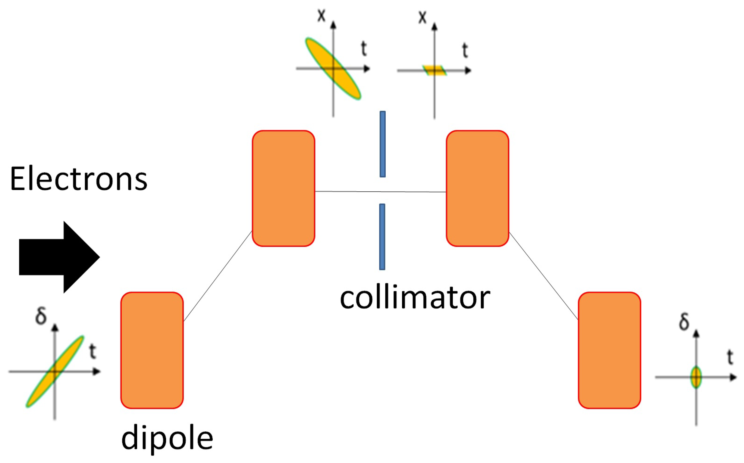
Figure 6.
Sketch of the SINBAD-ARES linac.

Figure 7.
Sketch of the SINBAD-ARES gun.

Figure 8.
Examples of electron bunches (Q = 0.5 pC) simulated in the ARES RF gun by using different settings of the photo-cathode laser. The plots showing the longitudinal phase space include the values of the coefficients for a fit of the beam distribution: , where is the longitudinal coordinate related to the beam center of charge position. The flexibility of the laser shaping allows for producing electron bunches with very different shapes of the longitudinal phase space and different non-linear components. The possibility of realizing a transversely flat-top profile allows for improving the non-linearity of the longitudinal phase space and the beam transverse emittance. Working closer to the so-called blow-out regime allows for further reducing the non-linear terms both in the transverse and in the longitudinal phase-space. The simulations have been performed using the code ASTRA [32].
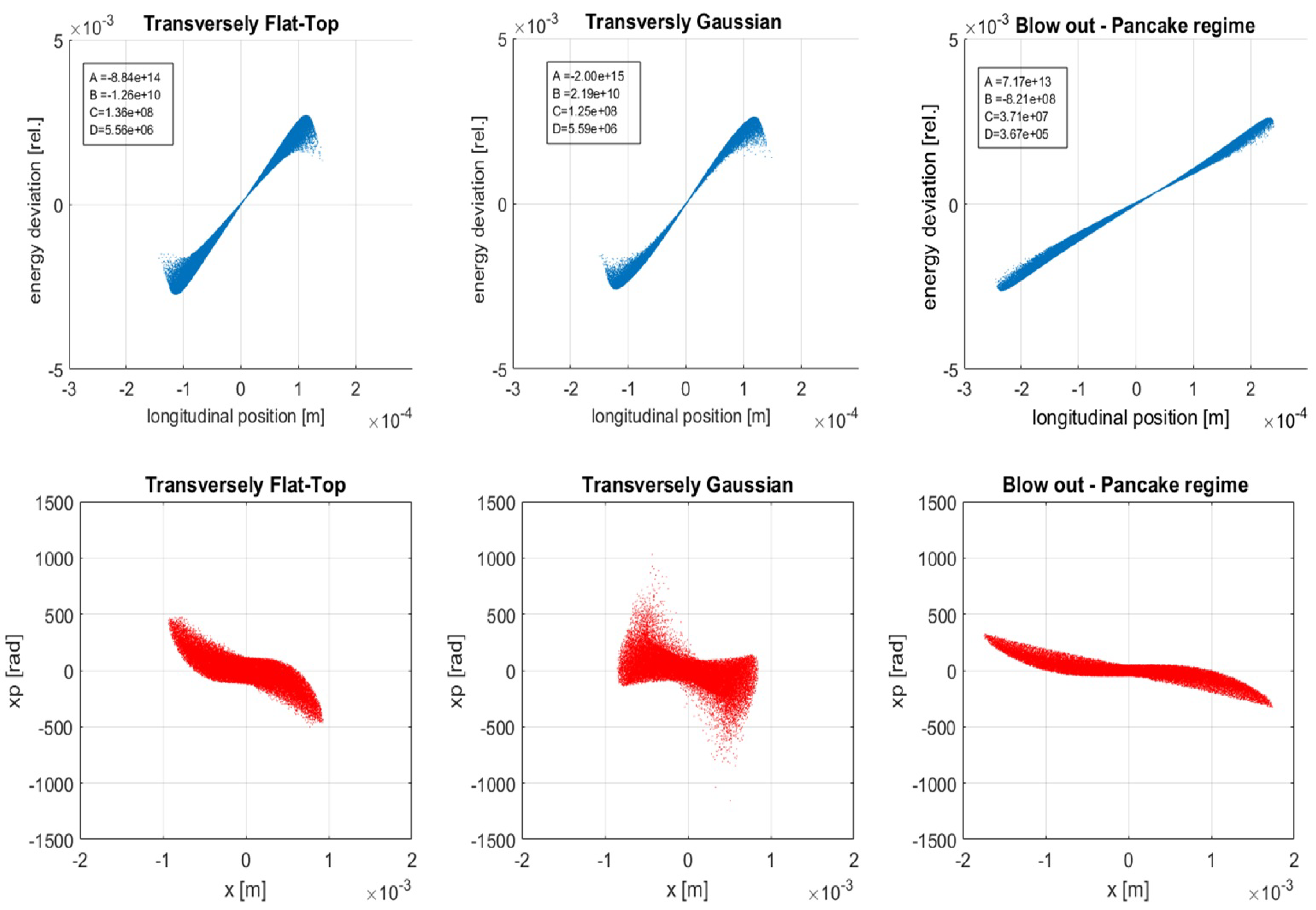
Figure 9.
Evolution of transverse emittance, longitudinal emittance and bunch length from the cathode to the linac entrance for the working-points represented in Figure 8.
Figure 9.
Evolution of transverse emittance, longitudinal emittance and bunch length from the cathode to the linac entrance for the working-points represented in Figure 8.

Figure 10.
Examples of electron bunches (Q = 20 pC) produced in the ARES RF gun by using different settings of the photo-cathode laser. By using a cigar-like shaping of the photo-cathode laser the slice emittance and the slice energy spread of the beam is minimized, whereas by working in the blow-out regime the longitudinal phase space becomes linear.
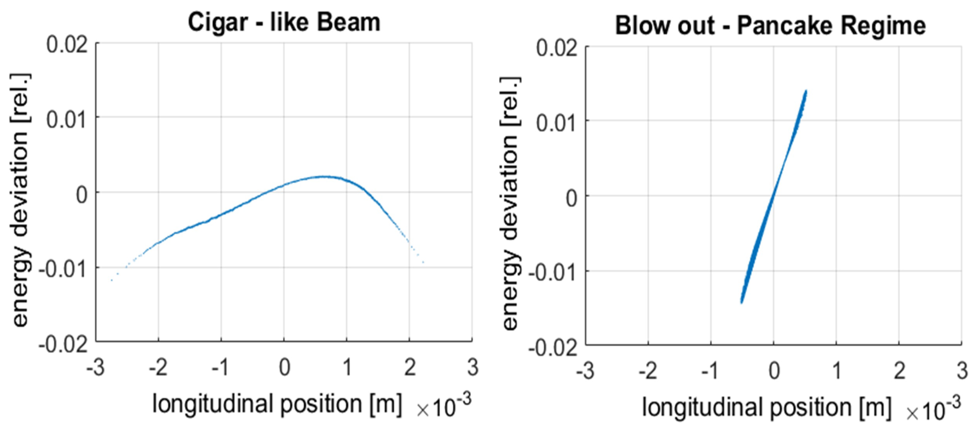
Figure 11.
Evolution of transverse emittance, longitudinal emittance and bunch length from the cathode to the linac entrance for the working-points represented in Figure 10.
Figure 11.
Evolution of transverse emittance, longitudinal emittance and bunch length from the cathode to the linac entrance for the working-points represented in Figure 10.

Figure 12.
Qualitative comparison of beam phase spaces at the exit of the bunch compressor using different physical models for space charge and CSR calculation in the bunch compressor [66]. For the simulations the particle codes IMPACT-T [75] and CSRTrack [76] have been used. In the figure the following abbreviations are used: SC = space charge, CSR = coherent synchrotron radiation.
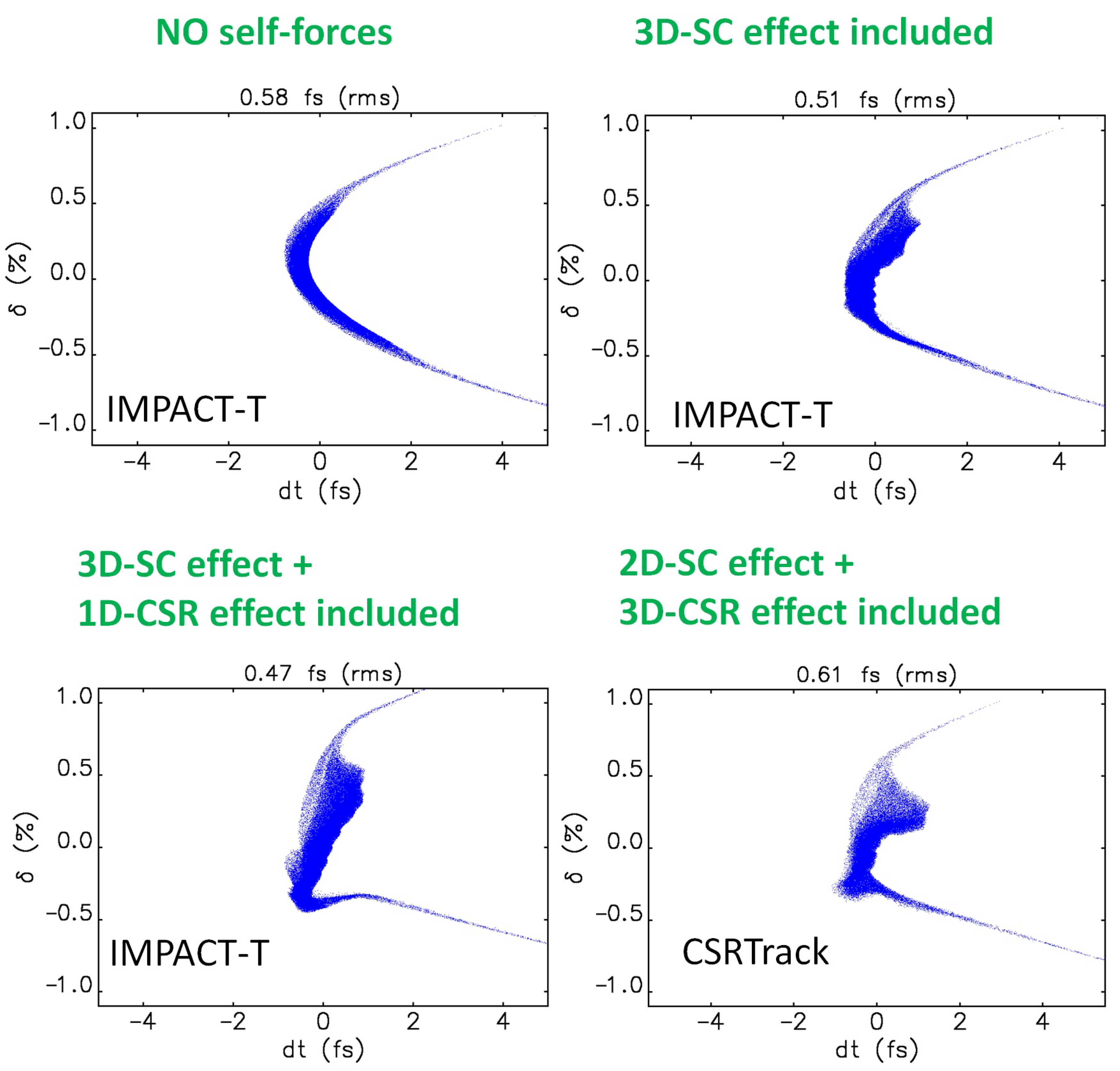
Figure 13.
Displacement and divergence of the beam at the injection point as a function of the laser displacement at the photocathode for WP2 (upper row) and WP4 (lower row) of the ARES linac. For both WP2 and WP4 Flat-Top transverse laser profile and Gaussian longitudinal laser profile were used. The RMS laser spot-size were 0.18 mm (WP2) and 0.17 mm (WP4), while the laser RMS duration were 3 ps (WP2) and 290 fs (WP4).
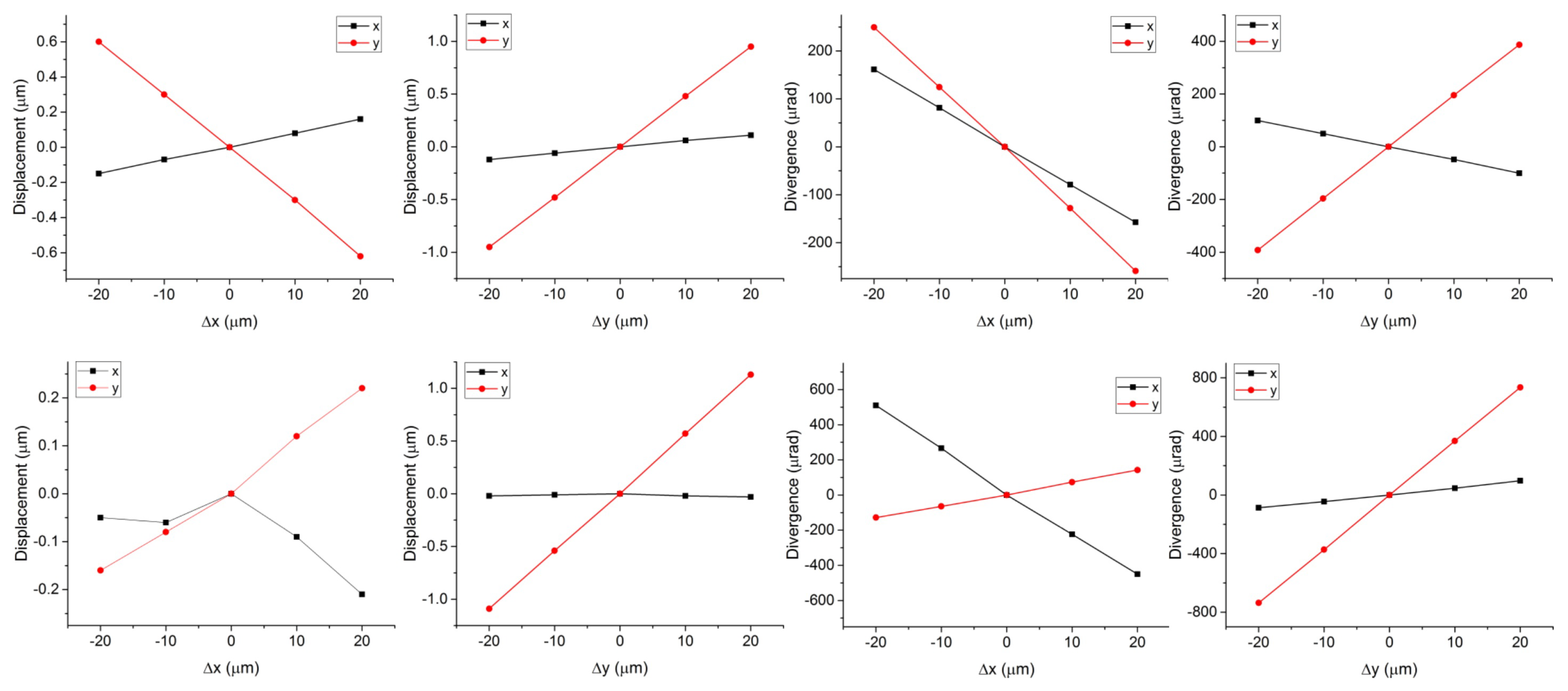
Figure 14.
The ARES linac and the associated infrastructure in the former DORIS facility.
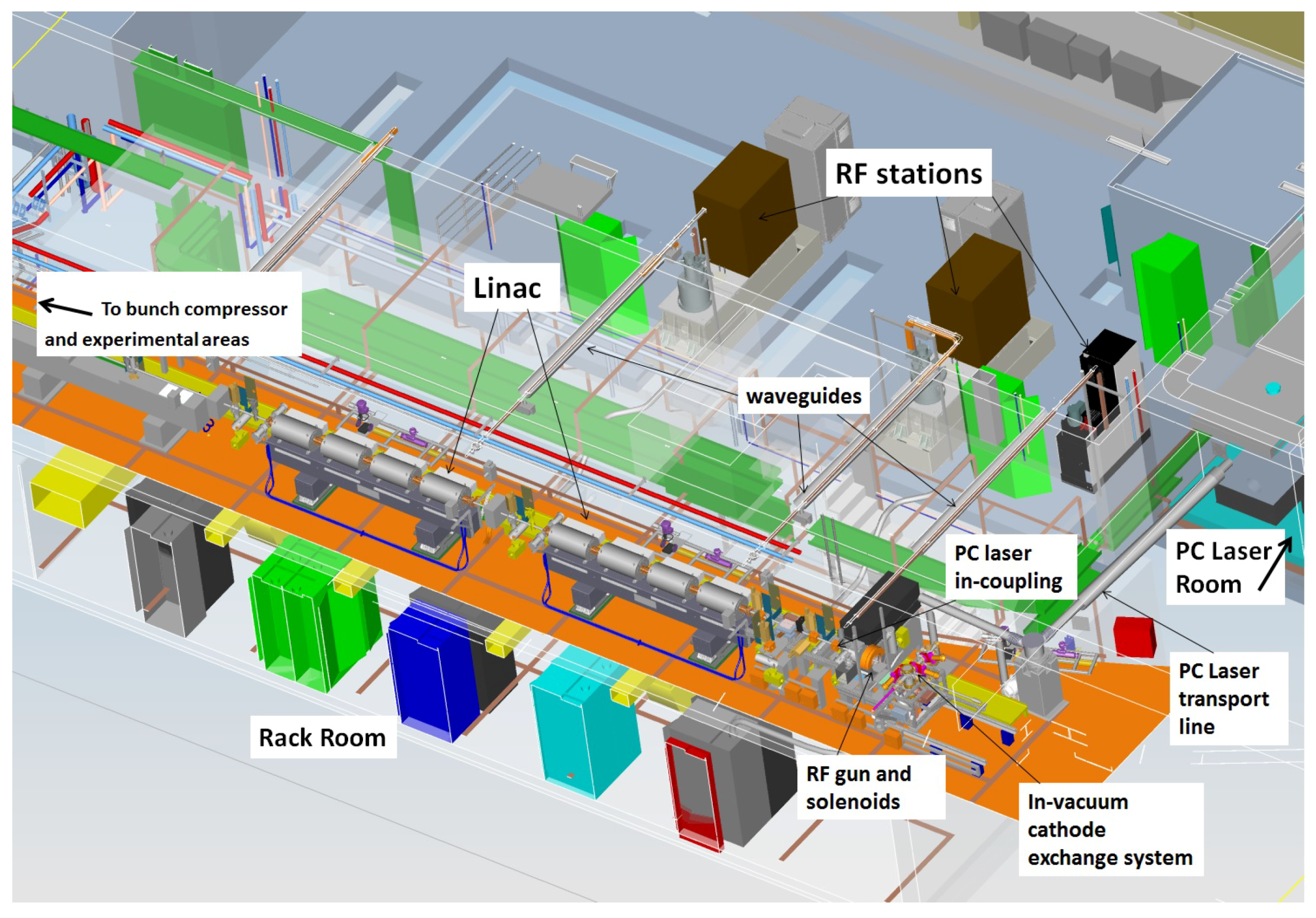

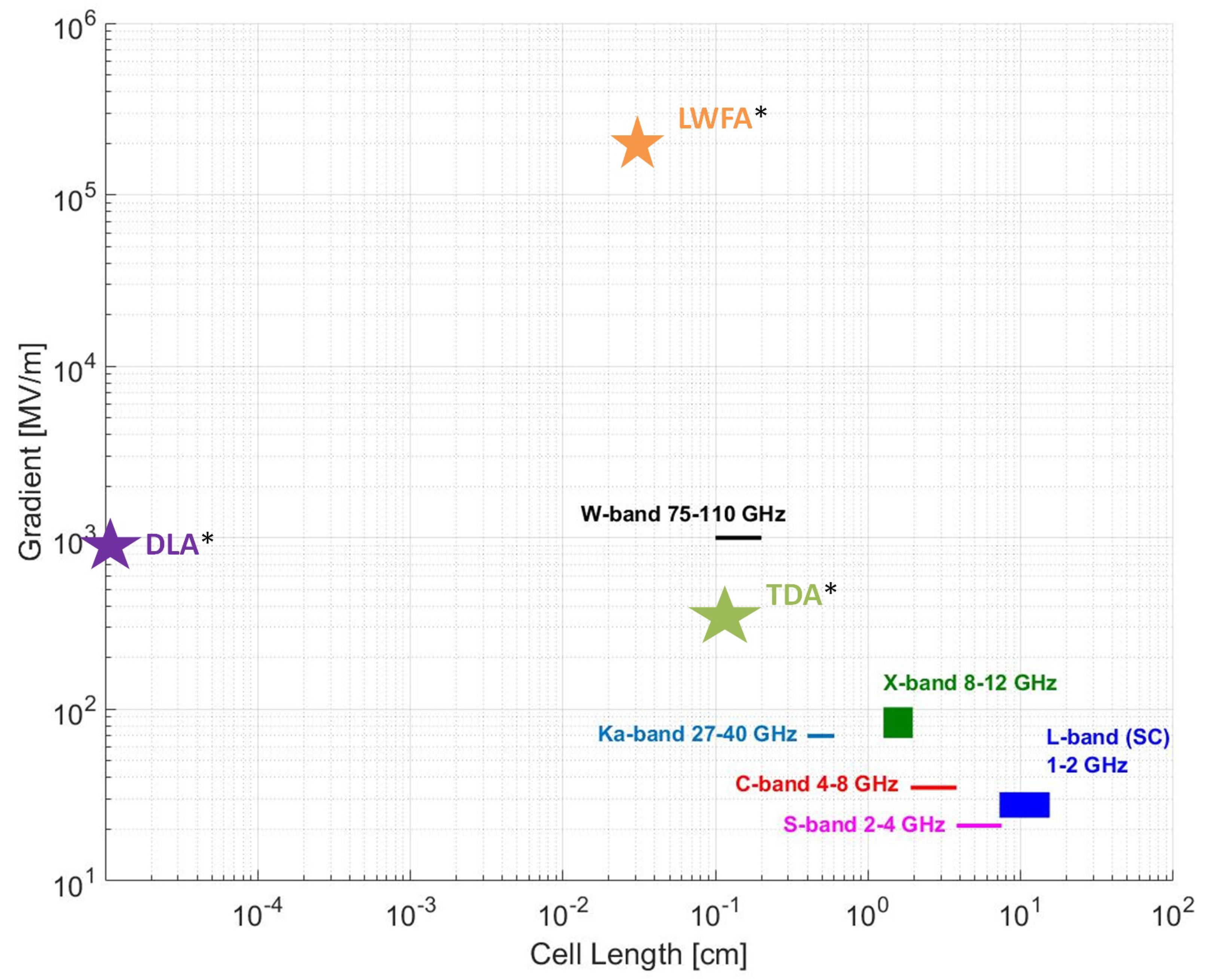
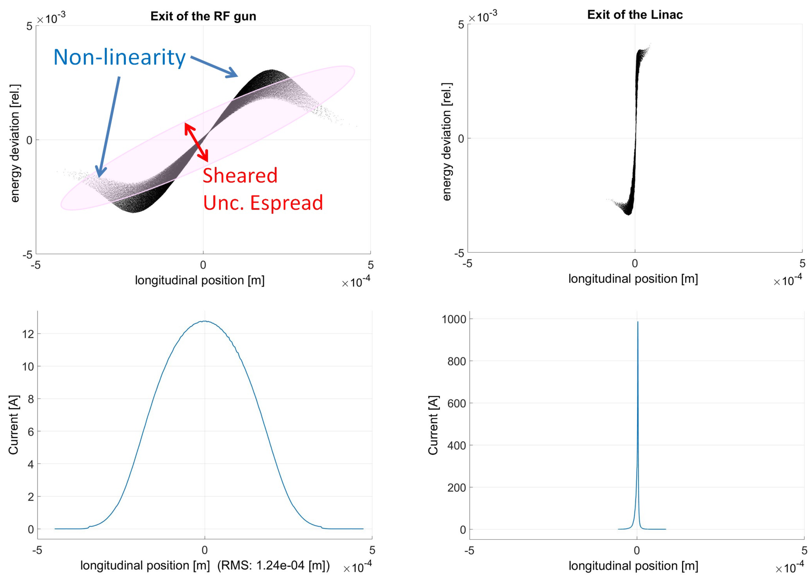
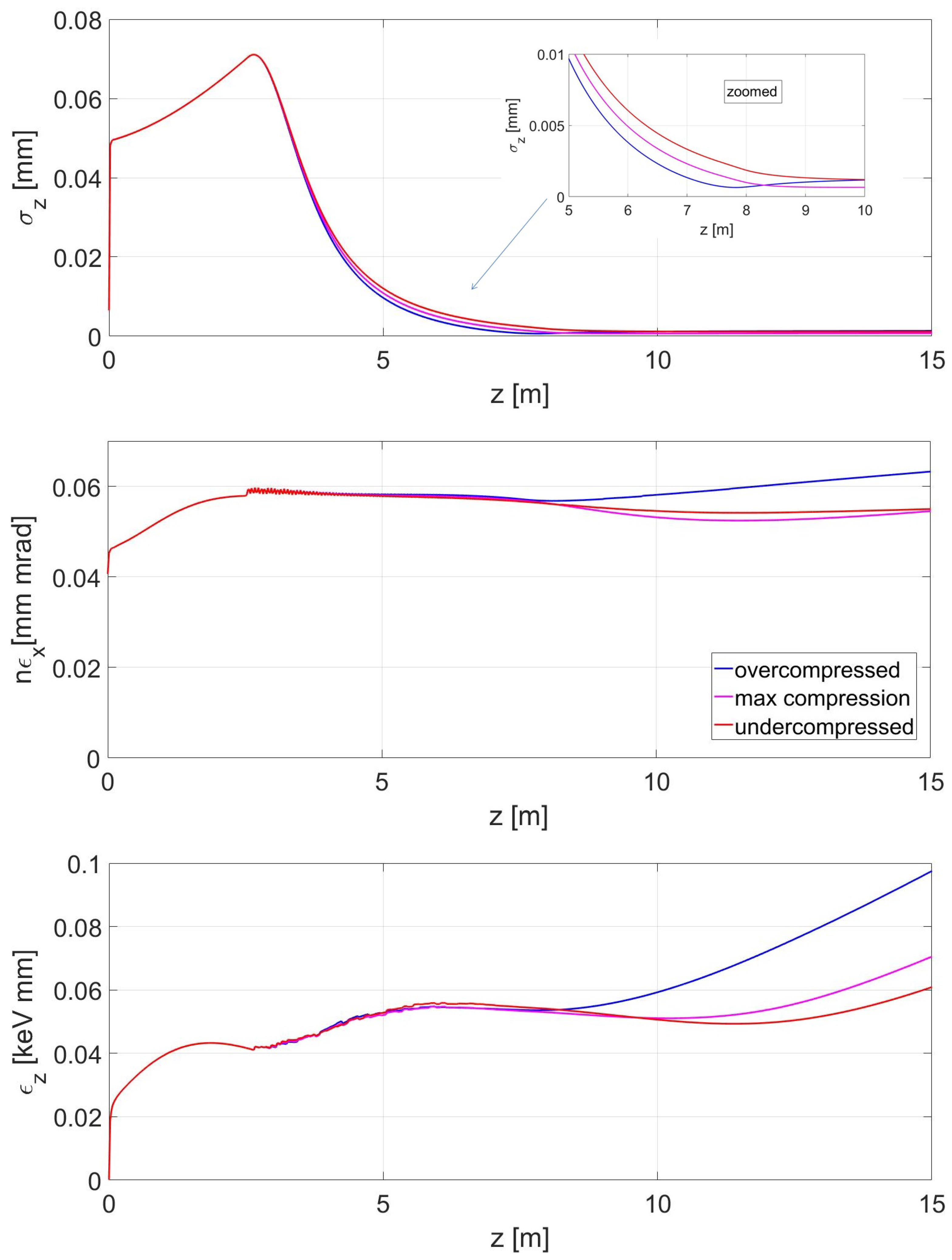
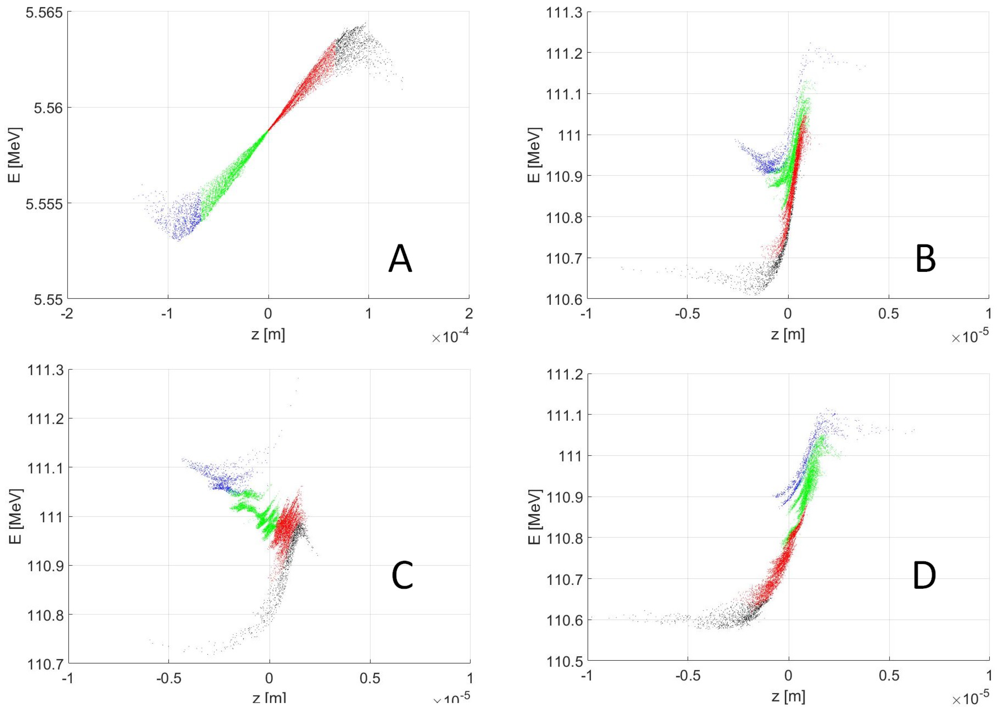
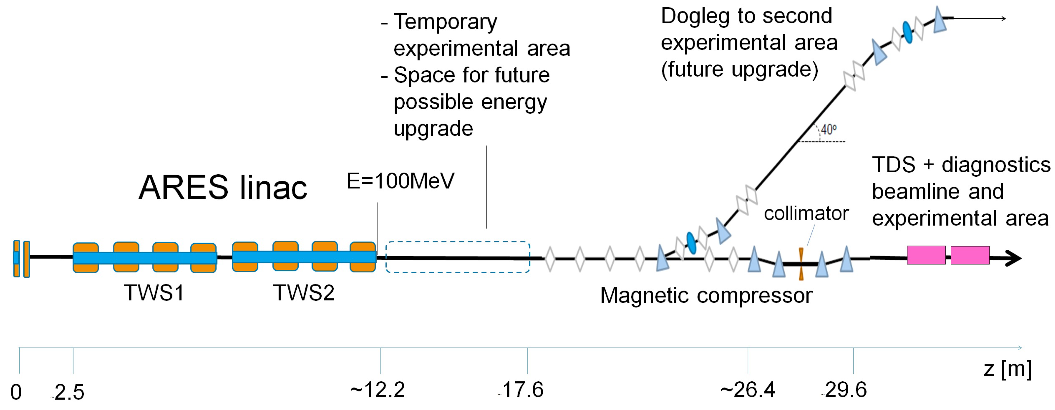
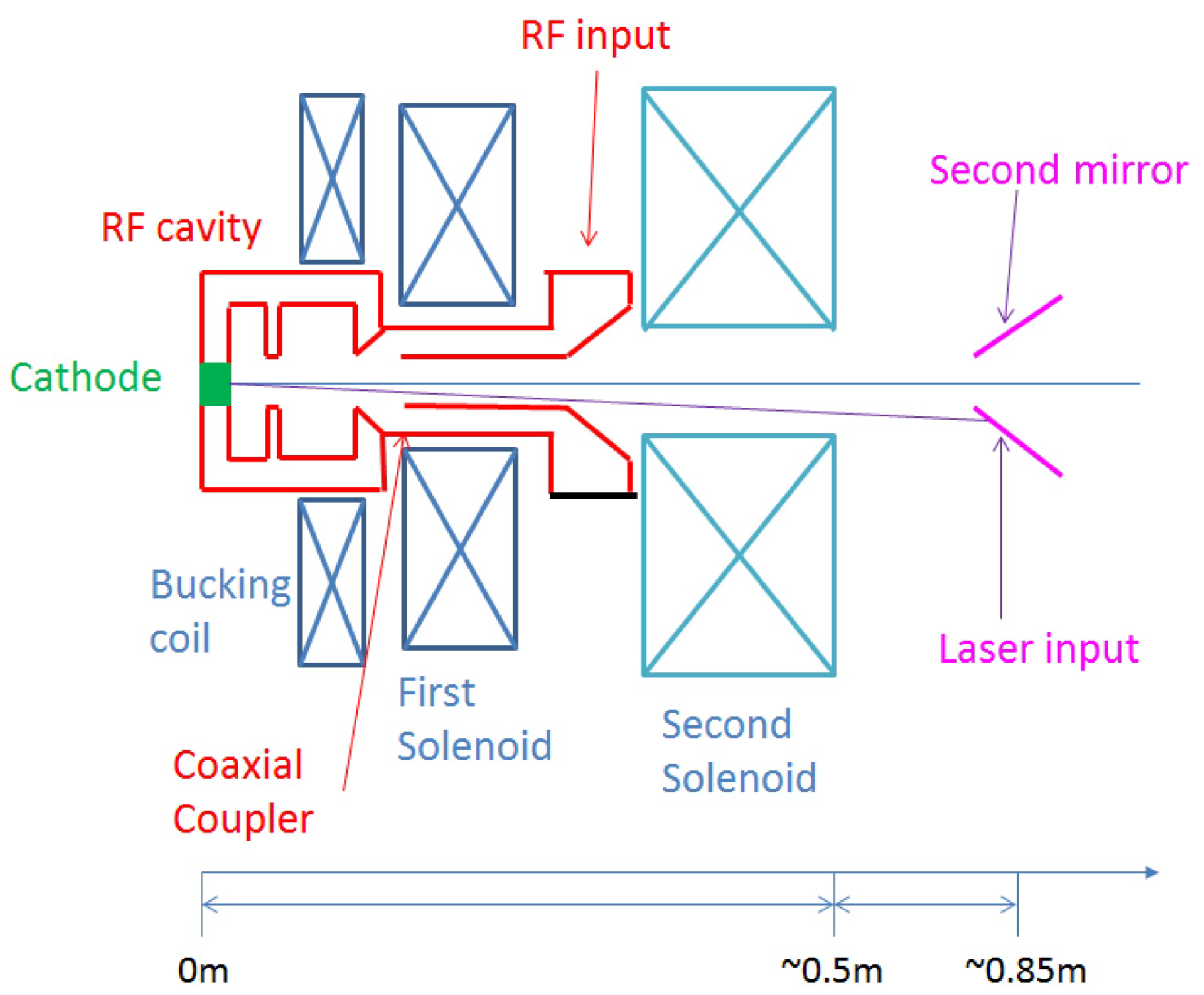
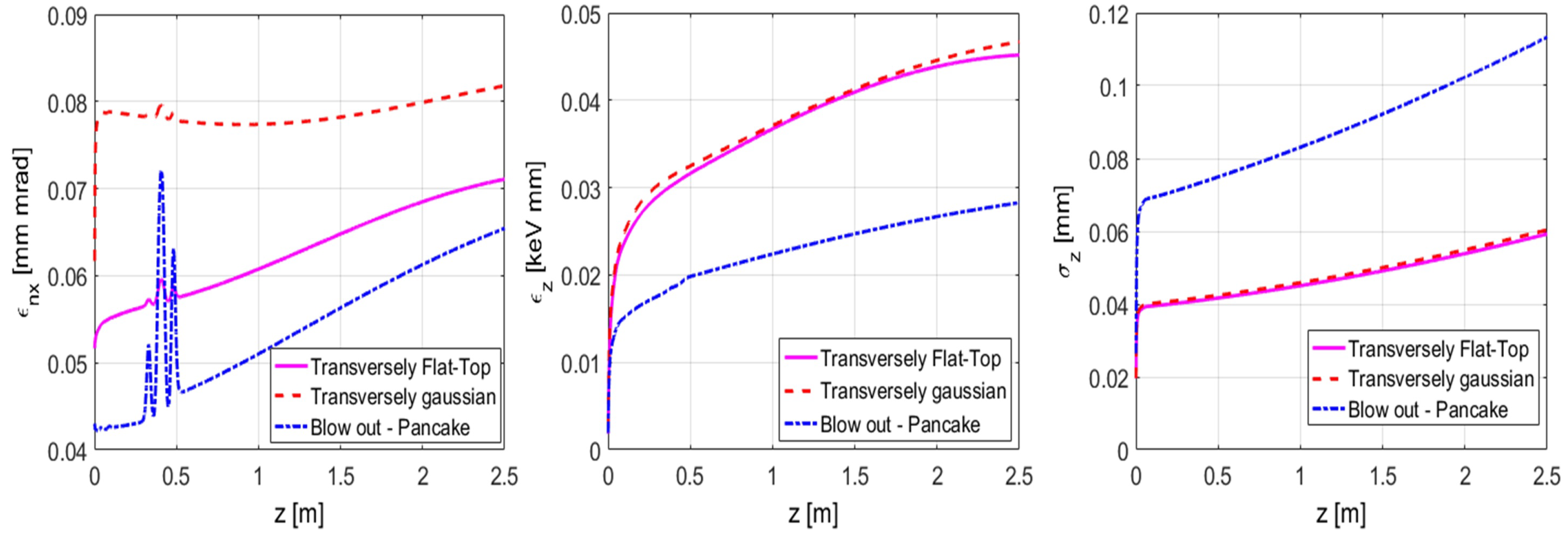
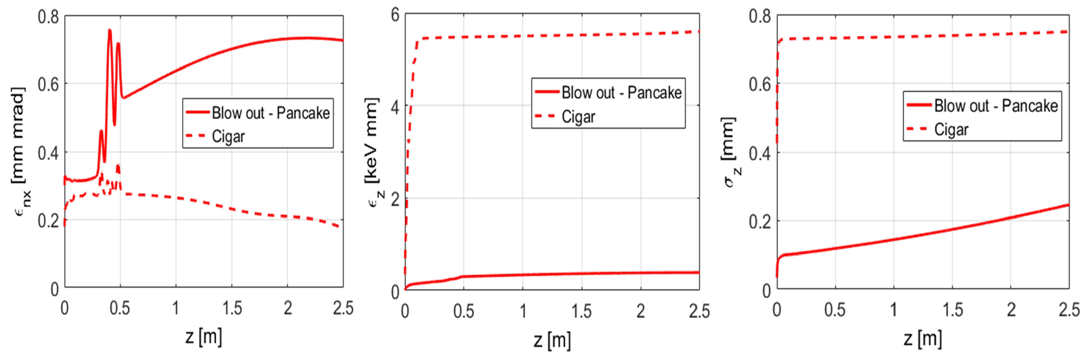
Table 1.
Overview of the order of magnitude of typical beam and field parameters for several laser-driven novel acceleration techniques. The listed repetition rates are typical values mainly limited by the lasers and they are not fundamental limitations of the acceleration method.
Table 1.
Overview of the order of magnitude of typical beam and field parameters for several laser-driven novel acceleration techniques. The listed repetition rates are typical values mainly limited by the lasers and they are not fundamental limitations of the acceleration method.
| Technique | Period Acc. Field [s] | Aperture Diameter [m] | Max Gradient [GV/m] | Rep. Rate [Hz] |
|---|---|---|---|---|
| LWFA | <10 cm | ∼ (matching condition) | >100 [4] | 1–50 |
| DLA | < | < | ∼1 | ∼ |
| TDA | < | ∼0.4 | 1– |
Table 2.
Examples of electric field parameters for different plasma densities estimated using the equations above.
Table 2.
Examples of electric field parameters for different plasma densities estimated using the equations above.
| Plasma Density [cm] | Wavelength [m] | Period [s] | Field Gradient (Lower Boundary) [GV/m] |
|---|---|---|---|
| 33 | 96 | ||
| 104 | 30 | ||
| 330 | 10 |
Table 3.
Laser and RF gun parameters used for obtaining the beam distributions shown in Figure 8 and Figure 9. All the working points presented are obtained for a bunch charge of 0.5 pC. In the last column, the transverse and longitudinal shaping of the laser profile are specified. The following abbreviations are used: FT = Flat-Top, Gauss = Gaussian.
| WP | [MV/m] | Laser RMS Spot [mm] | Laser RMS Length [ps] | Laser Trans/Long Shape |
|---|---|---|---|---|
| Transv. Flat-Top | 110 | 0.05 | 0.1 | FT/Gauss |
| Transv. Gaussian | 110 | 0.05 | 0.1 | Gauss/Gauss |
| Blow out | 70 | 0.04 | 0.076 | FT/Gauss |
Table 4.
Laser and RF gun parameters used for obtaining the beam distributions shown in Figure 10 and Figure 11. All the working points presented are obtained for a bunch charge of 20 pC. In the last column, the transverse and longitudinal shaping of the laser profile are specified. The following abbreviations are used: FT = Flat-Top, Gauss = Gaussian.
| WP | [MV/m] | Laser RMS Spot [mm] | Laser RMS Length [ps] | Laser Trans/Long Shape |
|---|---|---|---|---|
| Cigar | 110 | 0.088 | 3 | FT/Gauss |
| Blow out | 90 | 0.2 | 0.076 | FT/Gauss |
Table 5.
Summary of the beam characteristics after the bunch compressor for three working points. The peak current is defined as . The beam brightness is defined as . In the column with (*) of the particles in the tail were removed.
Table 5.
Summary of the beam characteristics after the bunch compressor for three working points. The peak current is defined as . The beam brightness is defined as . In the column with (*) of the particles in the tail were removed.
| [pC] | 0.8 | 5.7 | 17.3 |
| [pC] | 20 | 200 | 50 |
| [fs] | 0.5 | 2 | 12 |
| E [MeV] | 101 | 102 | 101 |
| [%] | 0.17 | 0.43 | 0.27 |
| [m] | 1.0 | 3.3 | 3.4 |
| [m] | 1.3 | 1.7 | 2.1 |
| [m] | 0.11 | 0.52 | 0.52 |
| [m] | 0.10 | 0.43 | 0.94 |
| [A] | 434 | 814 | 405 |
| B [] |
Table 6.
Comparison of the jitter tolerances corresponding to three typical working points in which the beam is compressed by velocity bunching (VB), magnetic compression (MC) or their combination (VB+MC). The tolerances have been studied in reference [77] using the code Elegant [79]. The elements in the table are defined in Figure 6. The line Magnetic field refers to the dipoles of the bunch compressor.
| MC | VB + MC | VB | |
|---|---|---|---|
| Laser-to-RF [fs] | 5950 | 160 | 125 |
| Gun charge [%] | 1.6 | 301.6 | 1010.1 |
| Gun phase [deg] | 0.78 | 0.61 | 0.49 |
| Gun Amplitude [%] | 1.14 | 0.72 | 0.40 |
| TWS1 Phase [deg] | 0.021 | 0.011 | 0.010 |
| TWS1 Amplitude [%] | 0.055 | 0.073 | 0.098 |
| TWS2 Phase [deg] | 0.022 | 0.13 | 4.21 |
| TWS2 Amplitude [%] | 0.064 | 0.040 | 1.155 |
| Magnetic field [%] | 0.030 | 0.030 | - |
© 2018 by the authors. Licensee MDPI, Basel, Switzerland. This article is an open access article distributed under the terms and conditions of the Creative Commons Attribution (CC BY) license (http://creativecommons.org/licenses/by/4.0/).
Share and Cite
MDPI and ACS Style
Marchetti, B.; Assmann, R.; Dorda, U.; Zhu, J. Conceptual and Technical Design Aspects of Accelerators for External Injection in LWFA. Appl. Sci. 2018, 8, 757. https://doi.org/10.3390/app8050757
AMA Style
Marchetti B, Assmann R, Dorda U, Zhu J. Conceptual and Technical Design Aspects of Accelerators for External Injection in LWFA. Applied Sciences. 2018; 8(5):757. https://doi.org/10.3390/app8050757
Chicago/Turabian StyleMarchetti, Barbara, Ralph Assmann, Ulrich Dorda, and Jun Zhu. 2018. "Conceptual and Technical Design Aspects of Accelerators for External Injection in LWFA" Applied Sciences 8, no. 5: 757. https://doi.org/10.3390/app8050757
Note that from the first issue of 2016, this journal uses article numbers instead of page numbers. See further details here.