Accurate and Detailed Transversal Road Section Characteristics Extraction Using Laser Scanner


University Institute for Automobile Research (INSIA), Universidad Politécnica de Madrid (UPM); 28031 Madrid, Spain
*
Author to whom correspondence should be addressed.
Appl. Sci. 2018, 8(5), 724; https://doi.org/10.3390/app8050724
Submission received: 15 February 2018
/
Revised: 6 April 2018
/
Accepted: 20 April 2018
/
Published: 5 May 2018
(This article belongs to the Special Issue Road Vehicles Surroundings Supervision: On-Board Sensors and Communications)
Abstract
:Road vehicle lateral positioning is a key aspect of many assistance applications and autonomous driving. However, conventional GNSS-based positioning systems and fusion with inertial systems are not able to achieve these levels of accuracy under real traffic conditions. Onboard perception systems provide knowledge of the surroundings of the vehicle, and some algorithms have been proposed to detect road boundaries and lane lines. This information could be used to locate the vehicle in the lane. However, most proposed algorithms are quite partial and do not take advantage of a complete knowledge of the road section. This paper proposes an integrated approach to the two tasks that provides a higher level of robustness of results: road boundaries detection and lane lines detection. Furthermore, the algorithm is not restricted to certain scenarios such as the detection of curbs; it could be also used in off-road tracks. The functions have been tested in real environments and their capabilities for autonomous driving have been verified. The algorithm is ready to be merged with digital map information; this development would improve results accuracy.
1. Introduction
New driver assistance systems (ADAS) require a more precise and detailed knowledge of the vehicle environment and its positioning [1]. These requirements are even greater when autonomous driving functions are introduced where, in many cases, knowledge of “where in the lane” is required [2]. However, conventional GNSS (Global Navigation Satellite System)-based positioning systems are not able to achieve these levels of accuracy under real traffic conditions, even when receivers that accept DGPS (Differential Global Positioning Systems) are available, since centimeter accuracy levels cannot be guaranteed along a whole route [3], much less so, in urban areas [4].
A solution that has been used for many years is the fusion of GNSS information with inertial systems (e.g., [5,6]). These inertial sensors have the disadvantage of drift along time, that causes a cumulative error that makes its use unviable over very large distances unless corrections are introduced by means of another positioning source. However, in areas where GNSS signal loss or deterioration is short, this fusion provides adequate results.
However, problems reappear in situations when the GNSS signal is zero, or bad over long distances, such as in tunnels or in urban areas of narrow streets. In such cases, even navigation systems that do not require high levels of precision do not work reliably [7]. Particularly critical examples are deviations inside tunnels.
Another solution for positioning that has been explored is the use of smartphones [8,9,10]. However, accuracy is far below what is required for many assistance systems, and autonomous driving and coverage problems could be common in certain scenarios.
The incorporation of sensors in vehicles for the perception of the environment for safety functions and autonomous driving (such as LiDAR—e.g., [11,12,13], computer vision—e.g., [14,15], radar—e.g., [16], or sensor fusion of some of them—e.g., [17,18]) has opened another field to improve positioning. Thus, different methods of visual odometry and SLAM (Simultaneous Localization and Mapping), based on computer vision and laser scanners, have emerged in recent years (e.g., [19,20,21,22]).
In this way, the sensors used for obstacle detection are also used as primary or secondary sensors for positioning and road mapping [23,24]. Thus, lane keeping systems are based, generally, on computer vision systems, and base their correct operation on the perception of the lines that delimit the lanes. However, the detection of lane lines presents deficiencies in complex scenarios with dense traffic, where other vehicles cover these marks, or due to the limitations of the sensors themselves, such as the malfunctioning under lighting changes in the case of computer vision [25], or for errors in the detection of badly maintained lines, areas with complex patterns on the road (merging lanes, exits, intersections, change in the number of lanes, or confusion with areas on the roadway due to maintenance operations). In addition, visual odometry methods also introduce cumulative errors in the calculation of trajectories, and SLAM algorithms require significant computational calculations when high precisions are required [26].
In this paper, a 3D laser scanner is used for transversal road characteristics detection, taking advantage of the use of this equipment for other purposes such as safety critical assistance systems or for autonomous driving. In this sense, there are solutions that seek to partially solve this problem. Such is the case of [27,28], that proposes a method for the detection of the curvature of the road with a 3D laser scanner, and introduces the use of the robust regression method—named least trimmed squares—to deal with occluding scenes. The curb detector is also used as an input to a Monte Carlo localization algorithm, which is capable of estimating the position of the vehicle without an accurate GPS sensor. Also, in [29] an approach for laser-based curb detection is presented. Other approaches to achieving higher levels of robustness in the detection of road lines are raised in [30]. Similarly, with similar equipment, [31] proposes algorithms for the detection of road boundaries.
The authors of [32] propose a system that is based on a formulation of stereo with homography as a maximum a posteriori (MAP) problem in a Markov random field (MRF). This solution, that uses computer vision, provides quite robust results even in complex scenarios. In [33], the free road surface ahead of the ego-vehicle using an onboard camera is detected. The main contribution is the use of a shadow-invariant feature space combined with a model-based classifier. The model is built online to improve the adaptability of the algorithm to the current lighting, and to the presence of other vehicles in the scene.
In other cases, the fusion of laser scanners and computer vision is used, as in [34], where the algorithm is based on clouds of 3D points and is evaluated using a 3D information from a pair of stereo cameras, and also from the laser scanner. To obtain a dense point cloud, the scanner cloud has been increased using Iterative Closest Point (ICP) with the previous scans.
Algorithms proposed in this paper are oriented for the positioning of the vehicle in the road with centimetric precision, even when the signals obtained from GNSS or inertial systems are not appropriate. The solution is based on the use of 3D laser scanner, and the algorithms pursue the detection of the boundaries of the road and the lanes, identifying the lane through which it circulates, and the lateral position (and, therefore, the identification of lane change maneuvers).
Unlike previous approaches, the algorithm proposed in this paper tries to increase the robustness of the results with a low computational cost (much faster than real time), using only laser scanner data and a digital map when available, even in complex scenarios, and to go through the detection of road boundaries and, subsequently, the detection of lanes in an integrated way, taking advantage of both results to increase global reliability and to improve partial approaches. The algorithm also accept the input of digital map information in order to improve results, but this additional information is not strictly necessary. Furthermore, the algorithms should work under different scenarios, rural and urban, considering that the road boundaries and the configurations of the lane lines could vary.
2. Algorithm
In order to locate the vehicle laterally on the road it is necessary firstly to know the transversal characteristics of the road. To do this, the algorithm shown in Figure 1 is proposed. The algorithm begins by obtaining the raw data from the laser scanner. From that set of points, the function of road boundaries detection that offers as output the width of the roadway is implemented. Two methods are considered in parallel. The same set of points serves as input data for the lane lines detection function, where the lane through which the ego-vehicle moves is distinguished from the rest, since it is expected that a greater density of points will be available for fitting. This second function offers lane widths as output. We proceed to evaluating whether the width obtained for each lane is included in a preset range, with which the shoulder can be differentiated from the other lanes, as well as checking if a line has been lost due to the lack of points of it; this implies the generation of a new estimated line between those already calculated. In the cases of both the lanes and the road boundaries calculation, when the functions do not offer satisfactory results, the information of the previous scan is used. Finally, the possibility of having a digital map is contemplated, which can be used to corroborate the number of lanes obtained (and use this feedback for the selection in the lane identification function) and classify them, distinguishing the lanes of the main roadway from the additional lanes as the merging or exit ones.
In the following subsections, the main functions of lane detection are described in detail.
Finally, after the road characteristics extraction process, it is simple to determine the lane through which the vehicle moves, its lateral position in, and if it should perform a lane change maneuvers.
2.1. Road Boundaries Detection Functions
The determination of the limits of the road is of interest for two main reasons. On the one hand, this calculation allows delimiting the area of interest for subsequent operations, such as the detection of obstacles [35], for example. On the other hand, in some roads, especially in urban areas, external lanes are not delimited by lines on one side, but their boundary is the curb that separates the road from the sidewalk.
Initially, two methods are proposed that make use of the geometric characteristics that suppose the end of the roadway.
- ⚬
- Method I: Study of the variations in the detection of each layer of the laser scanner.
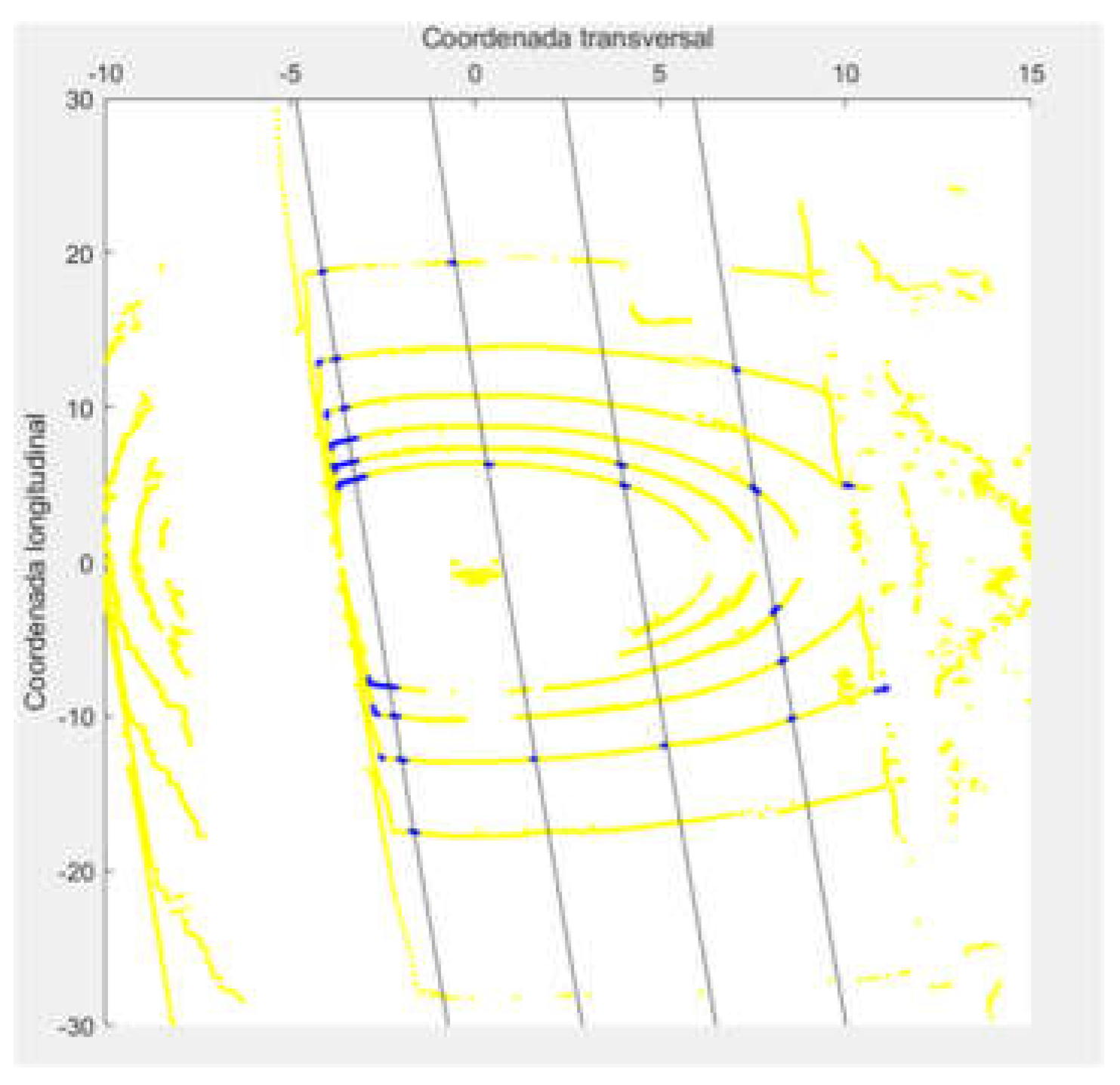
The intersection of each layer of the laser scanner with the plane of the road causes a roughly circular or elliptical section, depending on the relative inclinations, and may become other conics such as hyperbolas or parabolas, although these special cases are not relevant for this paper. The presence of the sidewalk at a height which is greater than the roadway involves cuts at different heights, so that, at the position of the curb, gradients occur at the Y (lateral) and Z (vertical) coordinates, which are significantly greater than those detected on the roadway (Figure 2).
In this way, laser scanner spots are studied in both dimensions, and the points where both gradient levels are higher than preset thresholds are detected. These thresholds have been adjusted using practical data from several scenarios, firstly using ideally simulated environments with typical dimensions, and then with practical data. Subsequently, the DBSCAN clustering function is applied in order to group all the points belonging to the curb and eliminate potential false detections, for example, because of vertical elements in the vicinity of the road. This process provides a set of points that distinguish the roadway from the surroundings because of the abrupt changes detected in curves detected by each layer of the laser scanner.
Then, in order to eliminate other false points that do not belong to the road, we proceed to adjust the points set to a plane using the M-estimator algorithm SAmple Consensus (MSAC), a variant of the RANdom algorithm SAmple Consensus (RAMSAC).
- ○
- Method II: Study of the separation between intersecting sections of consecutive laser scanner layers
This method is based on [27]. Considering the intersections of the layers of the laser scanner with the ground surface, the radius of the circumferences (assuming perpendicularity between the vertical axis of the laser scanner and the ground) depends on the height, so considering that the roadway is not in the same vertical dimension as the adjacent zones, a gradient in the radius of said intersection curves can be expected. It should be noted that both methods are based on the same concept (heights differences), but they provide quite different results, as practical tests demonstrate.
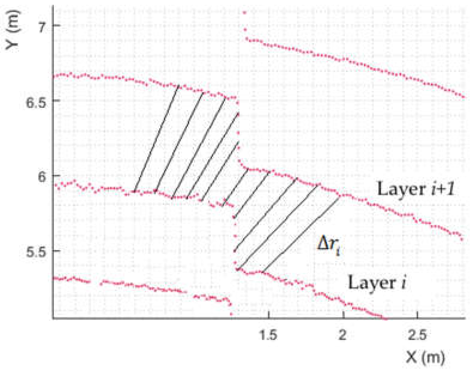
Figure 3 shows an example of the pavement-sidewalk transition and how the radius difference Δri of the detection circles between two consecutive layers varies. Although the curb could be identified as the zones of greater gradients, it has been shown that there are several cases where this solution induces errors in the detection of them, because of the presence of other obstacles near the curbs or the path boundaries; this fact inhibits the identification of those boundaries (there are multiple candidates). The solution proposed in the method is to try to identify areas with constant radius differences within a predefined tolerance, which allows determining the roadway area.
Since it is possible to accept points on the road that do not correspond to it, two additional filters are applied on the set of points detected: a height filter with which the points of each layer that differ significantly from the average height of the rest are discarded from points identified as roadway (potentially), and DBSCAN clustering algorithm.
2.2. Lane Lines Detection Function
From this first detection of the roadway, we proceed to the determination of the number of lanes, the lane through which the vehicle moves, and the lateral position of the vehicle in the lane. This function can be divided into the following steps:
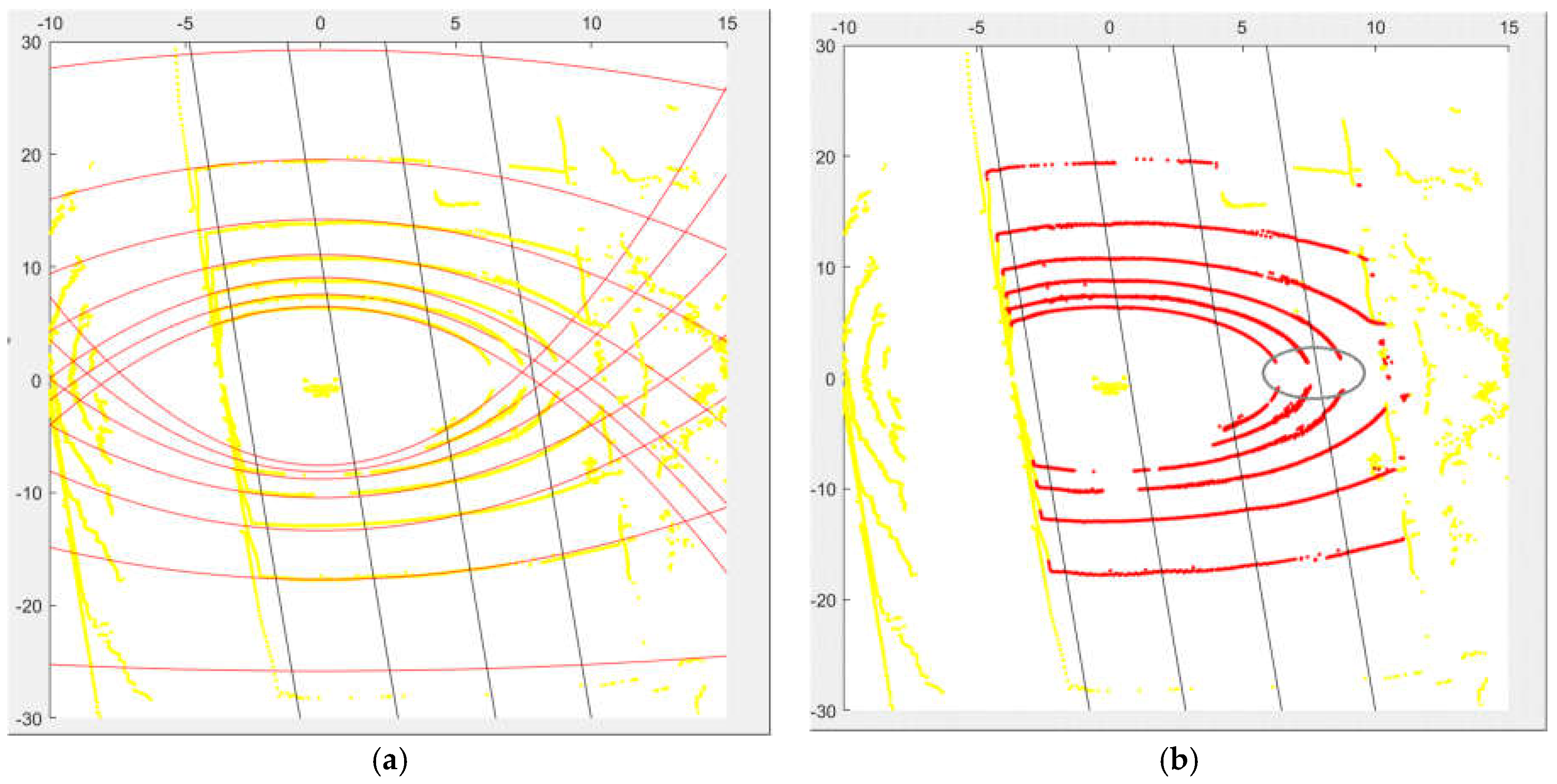
Step 1: On the area definition belonging to the roadway, it is possible to fit mathematical curves at each of the intersections of the layers of the laser scanner with the ground. The intersections of laser scanner layers and the ground form conics (in general, ellipses, parabolas and hyperbolas). Considering the common positioning of the scanner on vehicles, the intersection uses ellipses, so a least-square fitting method is applied to obtain the conical parameters. The points that fall away from this curve cannot be considered to belong to the roadway, but to obstacles on it, which allows them to be removed from the points set (Figure 4).
Step 2: Then, on the filtered point set, those points that show a greater reflectivity are extracted, having checked experimentally the remarkable contrast in this variable between the asphalt and the lines that delimit the lanes.
Step 3: On these points, geometric considerations are applied in order to eliminate false signals due to irregularities on the asphalt with high reflectivity that do not correspond to the road markings of lane delimitation. In this way, it is considered that, for the same layer, the dispersion of valid contiguous points must be small in the longitudinal direction, and large in transverse, if they are detected in front or behind the vehicle, and vice versa if they are located on the sides, due to the shape of the intersection curve of the layer with the ground. Figure 5 shows the output of steps 2 and 3 on a scanner frame. In most cases, a filtering process for this last step is not necessary because step 1 provides quite a good set of selected points, so few false points are considered after Step 2.
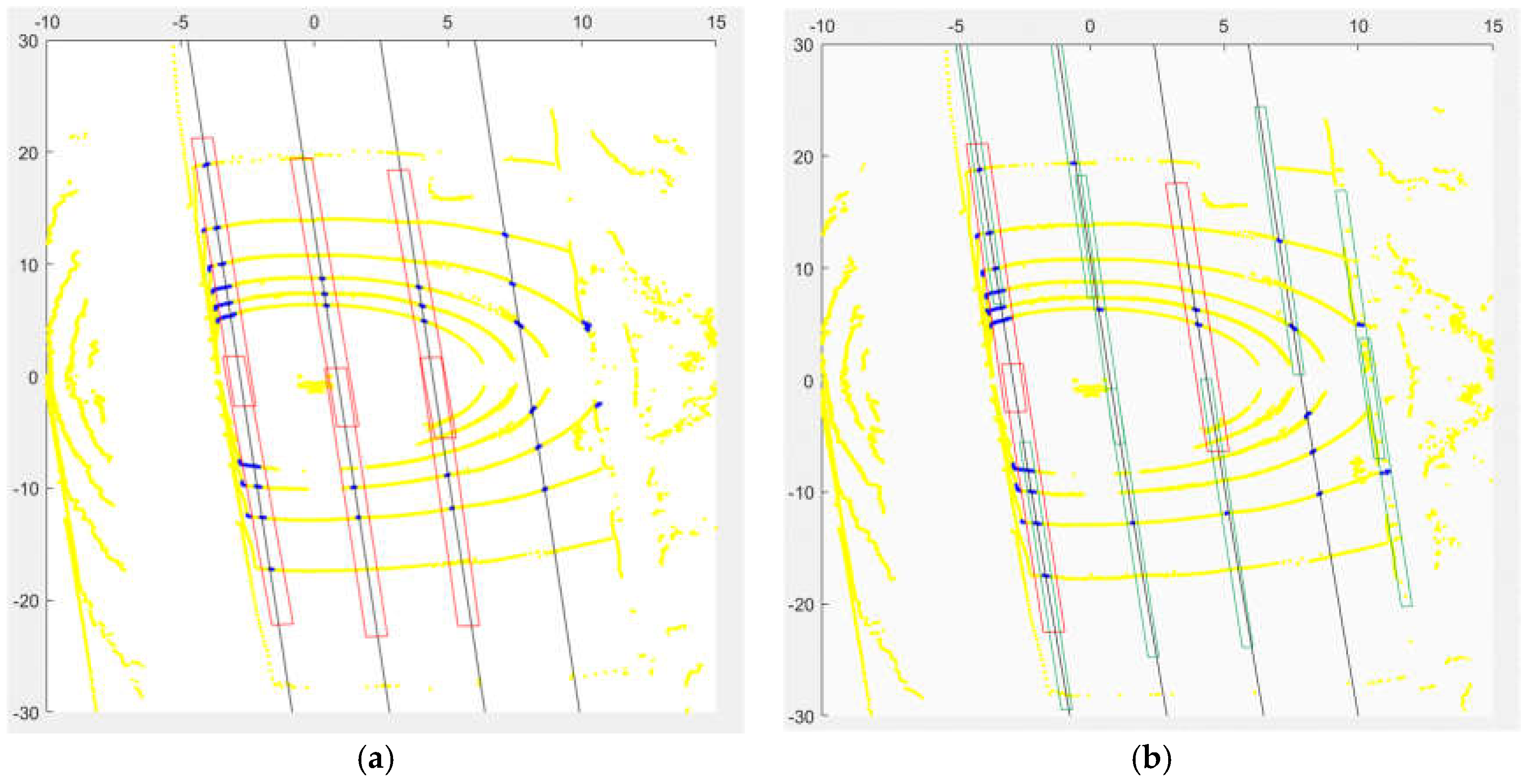
Step 4: The points clustering belonging to the same lane delimitation is done using knowledge of the relative orientation of the road with the vehicle (extracted from the previous function of road boundaries detection), and regions of interest are established around each set of points that, by proximity criteria, are considered to correspond to the same line. These regions of interest maintain the longitudinal direction of the points set, and extend a distance such that, considering the regulations about horizontal road markings, they must intersect if they correspond to the same line (Figure 6a).
Step 5: When points that may belong to the delimitation of lanes are detected but there is not enough data to establish the orientation of the area of interest, we proceed to generating new areas with the average orientation of those areas in which the density of nearby points allowed for the calculation (green areas in Figure 6b). It must be taken into account that, with the knowledge of the expected lane width, it is possible to determine if those isolated points can be part of a lane line or not. Additionally, the lane where the ego-vehicle is usually provides more information, although this is not necessarily true, due to possible occlusions of obstacles on the roadway.
Step 6: Then, we proceed to adjust the sets of points corresponding to lane delimitation lines. To do this, we proceed to a fitting process using quadratic polynomials, since they are considered to approximate reality [30]. Additionally, conditions of parallelism between the lines are considered, so equality conditions are imposed on linear and quadratic terms of the polynomials, as shown in Equation (1) for the curve equation representing lane line i (only coefficient ai varies from one line to another, but b and c are equal for all of them).
The least-squares fitting method is applied to obtain the N + 2 different coefficients, where N is the number of lanes lines. Equation (2) shows the calculation of the quadratic error committed in the curve fitting of lane line i, considering that Ni points have been selected in previous Steps for this line and their coordinates are (xij, yij) with j ranging from 1 to Ni.
Finally, the total error is calculated. It has been verified that the introduction of weighting factors that give greater relevance to the curves with a greater number of points increases the robustness of the overall adjustment. In particular, these coefficients are considered equal to the number of points detected for each line, so the equation that should be minimized is written as follows, considering that N lines have been distinguished:
Minimization of Equation (3) provides values of polynomials coefficients ai, b and c.
3. Results
In order to evaluate the results of the developed algorithm, road tests have been conducted in highway and urban areas. In them, a 16-layer Velodyne VLP-16 laser scanner was installed on top of a passenger car. Additionally, the trajectory was recorded by means of a Trimble R4 DGPS receiver, and the scenario was captured by a camera.
Firstly, the accuracy and robustness of the specific functions is assessed without the information from previous scans and information from digital map. Afterwards, the complete algorithm is considered to analyze whether misdetections of isolated functions could be solved in the proposed iterative loops.
In the first place, the differences of both methods for roadway delimitation are analyzed. Figure 7 shows an example of the use of the second method. Table 1 shows the comparison of the detection of curbs.
Detections at distances less or greater than 10 m are distinguished. This fact is relevant since the first layers acquired with the laser scanner provide a higher resolution and the first method presented above is especially sensitive to this fact. In this case, only in 28% of the frames is it possible to detect the curb more than 10 m in advance. In 67%, the detection is performed correctly, but at distances of less than 10 m, which greatly limits its applicability since the anticipation for any action or automatic control is very small. On the contrary, method II improves these results in a significant way, reaching a reliability index in the detection with a range greater than 10 m of 94% of the frames.
It should be noted that the first method is based on information from each laser layer, so the results are quite sensitive to any deviations that could appear in one layer. Other obstacles near the boundaries could lead to incorrect detections because they could be considered as the road boundaries following the method criteria. The second method relies on the information of two consecutive layers, so the impact of obstacles is reduced if it is only detected by one of the layers.
These results are obtained in real scenarios with traffic around the vehicle which causes occlusions of the curbs. Despite this, the degree of robustness detected for Method II is very high, and there are not a significant number of consecutive frames with erroneous detection, which would be quite limiting for autonomous driving applications. Furthermore, results take into account neither the information from previous scans nor a digital map.
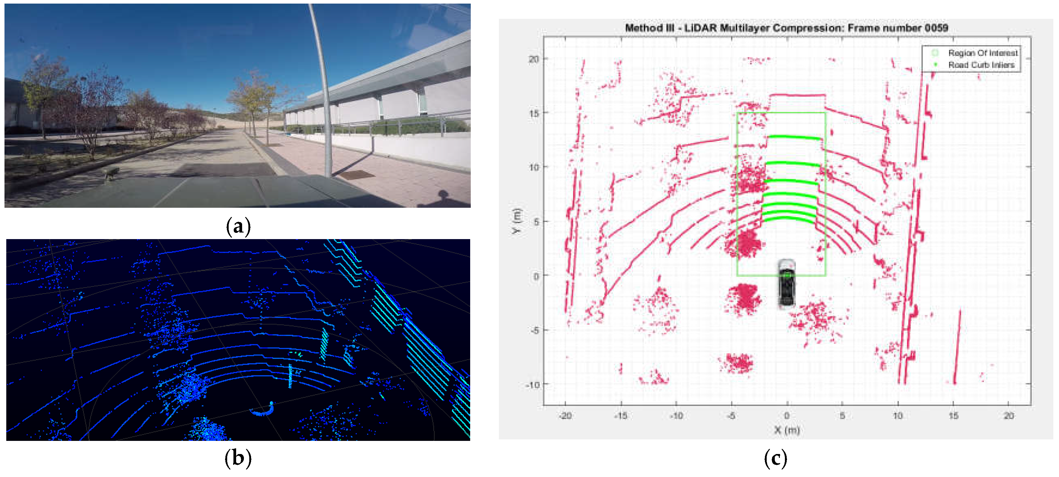
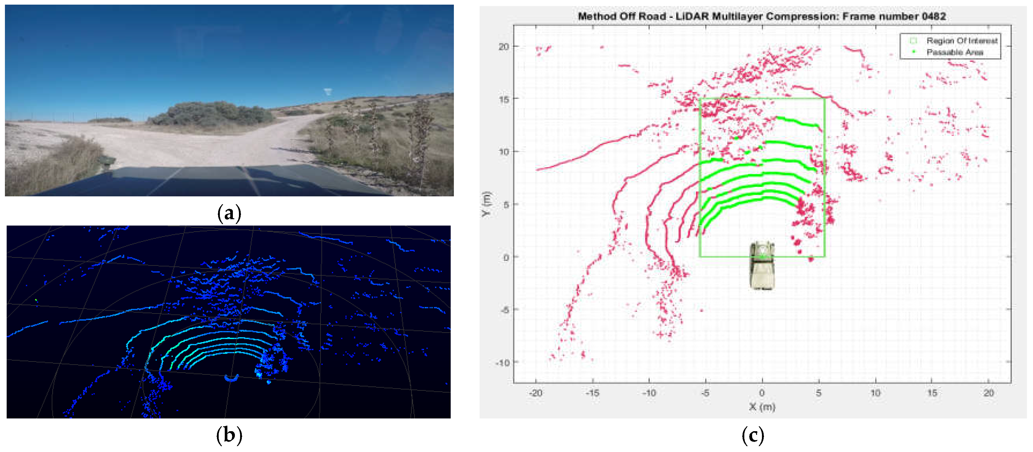
Additionally, it should be noted that the roadway detection function (Method II) has also been tested in off-road areas in order to differentiate passable areas from those that may not be. With a small computational cost, it is observed that satisfactory results are obtained, as can be seen in Figure 8, where the two possible paths are seen as passable, and they differ from the rest of the paths defined as non-passable.
Subsequently, the reliability of the function for determining the number of lanes has been checked. In this sense, it is necessary to distinguish the cases in which there are no singularities, such as merging lanes, exits or changes in the number of lanes, with scenarios in which one of those situations does occur. Table 2 shows the reliability of the function described in Section 3 in both scenarios. As can be seen, in areas without singularities, robustness is quite high even when the information from previous scan is not used (78% correct), while it is reduced in the case of road sections with singularities. Note that 47% accuracy is guaranteed, although this value is considered a lower threshold since it does not include those special cases where, for example, an additional lane appears as a merging or exit lane. In these cases, in the absence of a reference of a digital map, the function is not able to differentiate them from the lanes of the main roadway, so a conservative approach has been chosen not to include them in the correct detections, since they require additional information.
In this case, as in the case of the road boundaries detection, there are not many consecutive frames with incorrect detection, and these are mainly due to the occlusion of the lane lines by other vehicles. Furthermore, it should be noted that the reason for many incorrect detections or non-performed calculations is the presence of obstacles. But, as these perturbations do not remain for long periods of time, estimations of road boundaries and lane lines could be done using previous information.
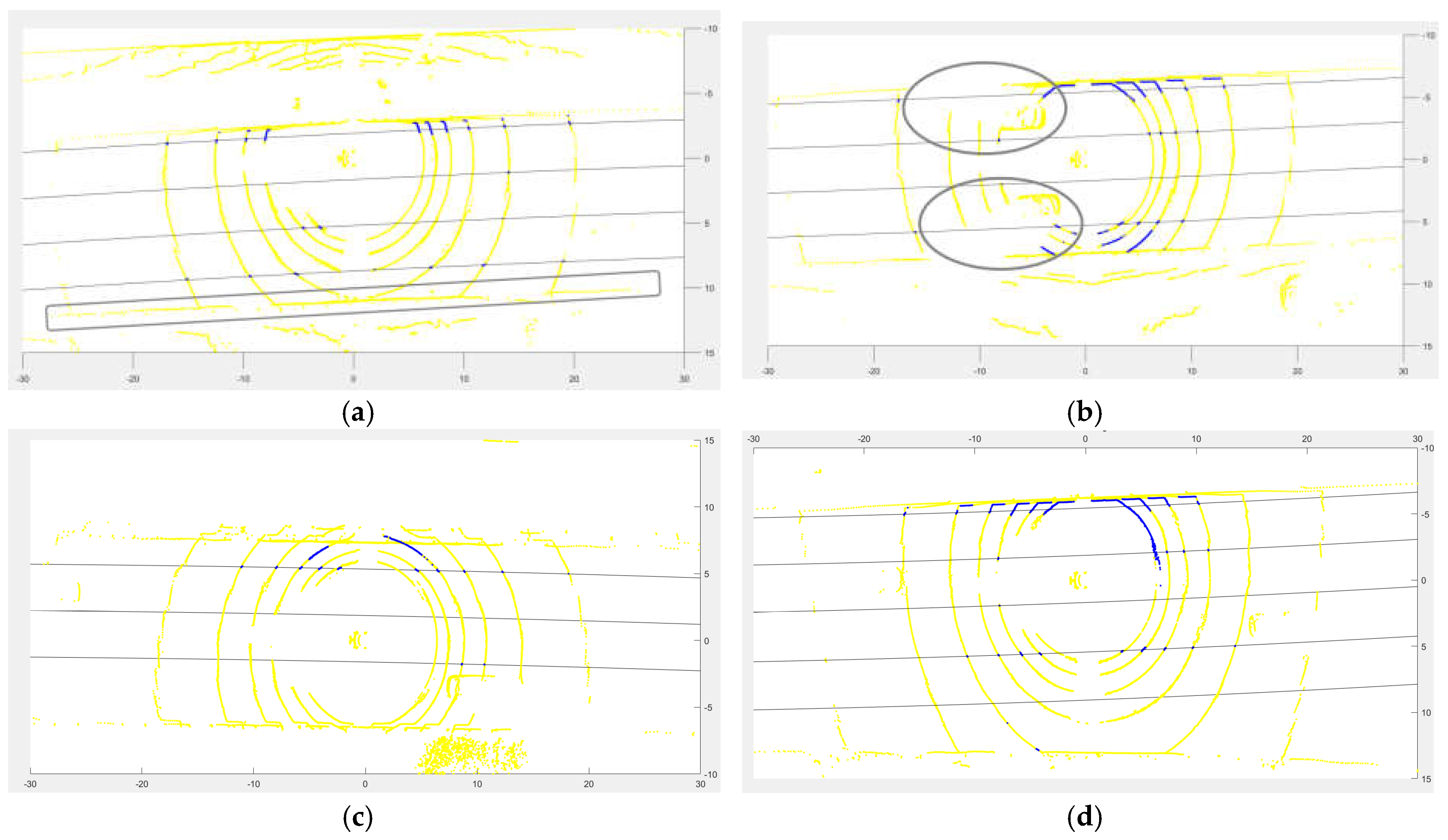
The study of the most frequent situations of erroneous or unrealized calculations shows the following conclusions:
- ○
- The shoulder can be identified as an additional lane, but has no influence on the detection of the other lanes after detection of the roadway boundaries in the first phase of the function (Figure 9a)
- ○
- Due to the presence of obstacles on the road (mainly, other vehicles), occlusions of the lane lines occur and, in extreme cases, complete information is lost relative to any of the lines (Figure 9b,c).
- ⚬
- In this case, the loss of information in the lane through which the vehicle moves is more critical, since the initial estimates of the function are based on it.
- ○
- The loss of information from the farthest lanes is less relevant, and causes errors in lane counting but not in the position of the vehicle on the road.
- ○
- The loss of information from an intermediate lane is usually solved approximately by the function when estimating standard lane widths in the absence of information.
- ○
- The presence of additional lanes can be reliably detected, but, in the absence of other information, they are not distinguished with respect to the main lanes of the roadway, as indicated above (Figure 9d)
In the two final cases, it should be noted that the identification of the boundaries of the roadway allows us to obtain approximate estimates of the information of the undetected lanes.
Finally, it should be noted that previous results from both functions show only their performance in an isolated mode; interactions between them or use of previous scans as Figure 1 states have not been considered in results of Table 1 and Table 2. Even in such circumstances, the road characteristics extraction partial functions provide quite accurate results in many cases. When using the information of previous scans, transversal road characteristics estimation is possible throughout the test. Furthermore, when using the information from a digital map, the lane lines and the number of lanes have been always properly identified. It should be noted that this number, and the lane widths, are parameters that imply interactions in the algorithm; however, some incorrect estimations could lead to convergence problems. These problems have not arisen, and this fact could be taken as a complete success rate (100%) in the tests performed in on-road scenarios.
4. Conclusions
In this paper, an algorithm has been presented that is able to characterize the transversal road section using 3D laser scanner, so that the boundaries of the road and the lines of separation of the lanes are identified, positioning the vehicle laterally in it, performing these functions in a coordinated manner to increase the reliability of the results. This positioning improves the accuracy that could be obtained with conventional means of GNSS or inertial systems when the loss or deterioration of satellite positioning extends over long stretches.
The tests carried out in real scenarios show the reliability of the detection of the road boundaries and the difficulties in estimating the number of lanes, especially in sections of the road where singularities, such as merging lanes, exits, crossings, etc. occur. In such situations, the reliability of the function falls notably, although it is estimated that final rates of correct detection could increase significantly with knowledge of the environment, for example, through the information of a digital map; therefore, the algorithms should contrast the information captured by the laser scanner with known information, instead of estimating information without any reference. However, results only show the operating mode without that external help of a digital map.
Additionally, the detected errors—although they are abundant in complex scenarios—do not appear in a continuous way, so reliable detections are mixed with other erroneous ones, but the first ones allow establishing a reference in positioning.
It should be noted that the proper functioning of the boundaries detection function in off road scenarios shows its robustness and versatility, which behaves satisfactorily in an environment for which it was initially not foreseen, since its calibration is oriented towards the transition between road and sidewalk. This function also correctly identifies the boundaries of the roadway with or without curbs, so it is not limited to the case of urban areas with these elements.
Despite the accurate results, the proposed approach could only be used for positioning in a practical way (from an economic point of view, and considering current state-of-the-art technology and costs) if the sensor is used for other purposes. This fact is not really a limitation when dealing with autonomous driving applications, because of the common current use of LiDAR technology, but this fact is not strictly the same when dealing with only assistance systems.
Finally, integration of computer vision could be used to enhance the extracted information, because of the capacity of managing other kinds of image properties (such as colors, contrast, etc.), and limitations of this technology could be mitigated by sensor fusion with the current laser scanners.
Author Contributions
F.J. conceived the complete algorithm, the applications for autonomous driving and supervised the results. M.C. performed the tests and helped in the algorithm approach. F.C. implemented and tested the lane lines detection function. C.Á. implemented and tested the roadway boundaries detection functions.
Acknowledgments
This work has received the support of the Spanish Ministerio de Economía y Competitividad MINECO (CAV project TRA2016-78886-C3-3-R), the Spanish Ministrio de Defensa (REMOTE DRIVE project 2015/SP03390102/00000035-10032/15/0029/00) and Madrid Region Excellence Network SEGVAUTO-TRIES.
Conflicts of Interest
The authors declare no conflict of interest.
References
- Jiménez, F.; Naranjo, J.E.; García, F.; Zato, J.G.; Armingol, J.M.; de la Escalera, A.; Aparicio, F. Limitations of positioning systems for developing digital maps and locating vehicles according to the specifications of future driver assistance systems. IET Intell. Transp. Syst. 2011, 5, 60–69. [Google Scholar] [CrossRef] [Green Version]
- Jiménez, F. Improvements in road geometry measurement using inertial measurement systems in datalog vehicles. Measurement 2011, 44, 102–112. [Google Scholar] [CrossRef]
- Naranjo, J.E.; Jiménez, F.; Aparicio, F.; Zato, J. GPS and inertial systems for high precision positioning on motorways. J. Navig. 2009, 62, 351–363. [Google Scholar] [CrossRef]
- Jiménez, F.; Monzón, S.; Naranjo, J.E. Definition of an Enhanced Map-Matching Algorithm for Urban Environments with Poor GNSS Signal Quality. Sensors 2016, 16, 193. [Google Scholar] [CrossRef] [PubMed]
- Sasiadek, J.Z.; Hartana, P. GPS/INS Sensor Fusion for Accurate Positioning and Navigation Based on Kalman Filtering. IFAC Proc. Vol. 2004, 37, 115–120. [Google Scholar] [CrossRef]
- Melendez-Pastor, C.; Ruiz-Gonzalez, R.; Gomez-Gil, J. A data fusion system of GNSS data and on-vehicle Sensors data for improving car positioning precision in urban environments. Expert Syst. Appl. 2017, 80, 28–38. [Google Scholar] [CrossRef]
- Jiménez, F. The Role of Digital Road Maps in the Future. In Highways: Construction, Management and Maintenance; Nova Publishers: Hauppauge, NY, USA, 2010; ISBN 978-1617288623. [Google Scholar]
- Zandbergen, P.A. Accuracy of iPhone locations: A comparison of assisted GPS, WiFi and cellular positioning. Trans. GIS 2009, 13, 5–25. [Google Scholar] [CrossRef]
- Engelbrecht, J.; Booysen, M.J.; van Rooyen, G.J.; Bruwer, F.J. Survey of smartphone-based sensing in vehicles for intelligent transportation system applications. IET Intell. Transp. Syst. 2015, 9, 924–935. [Google Scholar] [CrossRef]
- Wahlström, J.; Skog, L.; Händel, P. Smartphone-based Vehicle Telematics—A Ten-Year Anniversary. IEEE Trans. Intell. Transp. Syst. 2017, 18, 2802–2825. [Google Scholar] [CrossRef]
- Asvadi, A.; Premebida, C.; Peixoto, P.; Nunes, U. 3D Lidar-based static and moving obstacle detection in driving environments: An approach based on voxels and multi-region ground planes. Robot. Auton. Syst. 2016, 83, 99–311. [Google Scholar] [CrossRef]
- Guo, J.; Tsai, M.; Han, J. Automatic reconstruction of road surface features by using terrestrial mobile lidar. Autom. Constr. 2015, 58, 165–175. [Google Scholar] [CrossRef]
- García, F.; Jiménez, F.; Naranjo, J.E.; Zato, J.G.; Aparicio, F.; Armingol, J.M.; de la Escalera, A. Environment perception based on LIDAR sensors for real road applications. Robotica 2011, 30, 185–193. [Google Scholar] [CrossRef] [Green Version]
- Caraffi, C.; Cattani, S.; Grisleri, P. Off-road path and obstacle detection using decision networks and stereo vision. IEEE Trans. Intell. Transp. Syst. 2007, 8, 607–618. [Google Scholar] [CrossRef]
- Hernández-Aceituno, J.; Acosta, L.; Piñeiro, J.D. Pedestrian Detection in Crowded Environments through Bayesian Prediction of Sequential Probability Matrices. J. Sens. 2016, 2016, 4697260. [Google Scholar] [CrossRef]
- Tokoro, S.; Kuroda, K.; Nagao, T.; Kawasaki, T.; Yamamoto, T. Pre-crash sensor for pre-crash safety. In Proceedings of the International Conference on Enhanced Safety of Vehicles, Gothenburg, Sweden, 8–11 June 2015. [Google Scholar]
- Zhang, X.; Zhang, A.; Meng, X. Automatic fusion of hyperspectral images and laser scans using feature points. J. Sens. 2015, 2015, 415361. [Google Scholar] [CrossRef]
- Chavez-Garcia, R.O.; Aycard, O. Multiple Sensor Fusion and Classification for Moving Object Detection and Tracking. IEEE Trans. Intell. Transp. Syst. 2016, 17, 525–534. [Google Scholar] [CrossRef]
- Demim, F.; Nemra, A.; Louadj, K. Robust SVSF-SLAM for Unmanned Vehicle in Unknown Environment. IFAC-PapersOnLine 2016, 49, 386–394. [Google Scholar] [CrossRef]
- Pierzchała, M.; Giguère, P.; Astrup, R. Mapping forests using an unmanned ground vehicle with 3D LiDAR and graph-SLAM. Comput. Electron. Agric. 2018, 145, 217–225. [Google Scholar] [CrossRef]
- Nicolai, A.; Skeele, R.; Eriksen, C.; Hollinger, G.A. Deep Learning for Laser Based Odometry Estimation; Automation and the Oregon Metal Initiative; University of Oregon: Eugene, OR, USA, 2016. [Google Scholar]
- Zhang, J.; Singh, S. LOAM: Lidar Odometry and Mapping in Real-time. In Proceedings of the Robotics: Science and Systems Conference, Berkeley, CA, USA, 12–16 July 2014. [Google Scholar]
- Castro, M.; Lopez-Cuervo, S.; Paréns-González, M.; de Santos-Berbel, C. LIDAR-based roadway and roadside modelling for sight distance studies. Surv. Rev. 2016, 48, 309–315. [Google Scholar] [CrossRef]
- Holgado-Barco, A.; Riveiro, B.; González-Aguilera, D.; Arias, P. Automatic Inventory of Road Cross-Sections from Mobile Laser Scanning System. Comput.-Aided Civ. Infrastruct. Eng. 2017, 32, 3–17. [Google Scholar] [CrossRef]
- Fuerstenberg, K.C.; Baraud, P.; Caporaletti, G.; Citelli, S.; Eitan, Z.; Lages, U.; Lavergne, C. Development of a pre-crash sensorial system—The CHAMELEON project. In Proceedings of the Joint VDI/VW Congress Vehicle Concepts for the 2nd Century of Automotive Technology, Wolfsburg, Germany, November 2001. [Google Scholar]
- De la Escalera, A.; Izquierdo, E.; Martín, D.; Musleh, B.; García, F.; Armingol, J.M. Stereo visual odometry in urban environments based on detecting ground features. Robot. Auton. Syst. 2016, 80, 1–10. [Google Scholar] [CrossRef]
- Hata, A.; Osorio, F.S.; Wolf, D. Curb Detection and Vehicle Localization in Urban Environments. In Proceedings of the IEEE Intelligent Vehicles Symposium, Dearborn, MI, USA, 8–11 June 2014. [Google Scholar]
- Hata, A.; Wolf, D.F. Road Marking Detection Using LiDAR Reflective Intensity Data and its Application to Vehicle Localization. In Proceedings of the IEEE 17th International Conference on Intelligent Transportation Systems (ITSC), Qingdao, China, 8–11 October 2014. [Google Scholar]
- Zhao, G.; Yuan, J. Curb Detection and Tracking Using 3D-Lidar Scanner. In Proceedings of the 19th IEEE International Conference on Image Processing (ICIP), Orlando, FL, USA, 30 September–3 October 2012. [Google Scholar]
- Jimenez, F.; Clavijo, M.; Naranjo, J.E.; Gómez, O. Improving the lane reference detection for autonomous road vehicle control. J. Sens. 2016, 2016, 9497524. [Google Scholar] [CrossRef]
- Zhang, W. Lidar-based road and road-edge detection. In Proceedings of the Intelligent Vehicles Symposium, 2010 IEEE Intelligent Vehicles Symposium, San Diego, CA, USA, 21–24 June 2010. [Google Scholar]
- Guo, C.; Mita, S.; McAllester, D. Robust road detection and tracking in challenging scenarios based on markov random fields with unsupervised learning. IEEE Trans. Intell. Transp. Syst. 2012, 13, 1338–1354. [Google Scholar] [CrossRef]
- Alvarez, J.; Lopez, A. Road detection based on illuminant invariance. IEEE Trans. Intell. Transp. Syst. 2011, 12, 184–193. [Google Scholar] [CrossRef]
- Fernandez, C.; Llorca, D.F.; Stiller, C.; Sotelo, M.A. Curvature-based Curb Detection Method in Urban Environments using Stereo and Laser. In Proceedings of the 2015 IEEE Intelligent Vehicles Symposium (IV), Seoul, Korea, 28 June–1 July 2015. [Google Scholar]
- Jiménez, F.; Naranjo, J.E. Improving the obstacle detection and identification algorithms of a laserscanner-based collision avoidance system. Transp. Res. Part C Emerg. Technol. 2011, 19, 658–672. [Google Scholar] [CrossRef]
Figure 1.
Flowchart for the extraction of the transversal characteristics of the road.
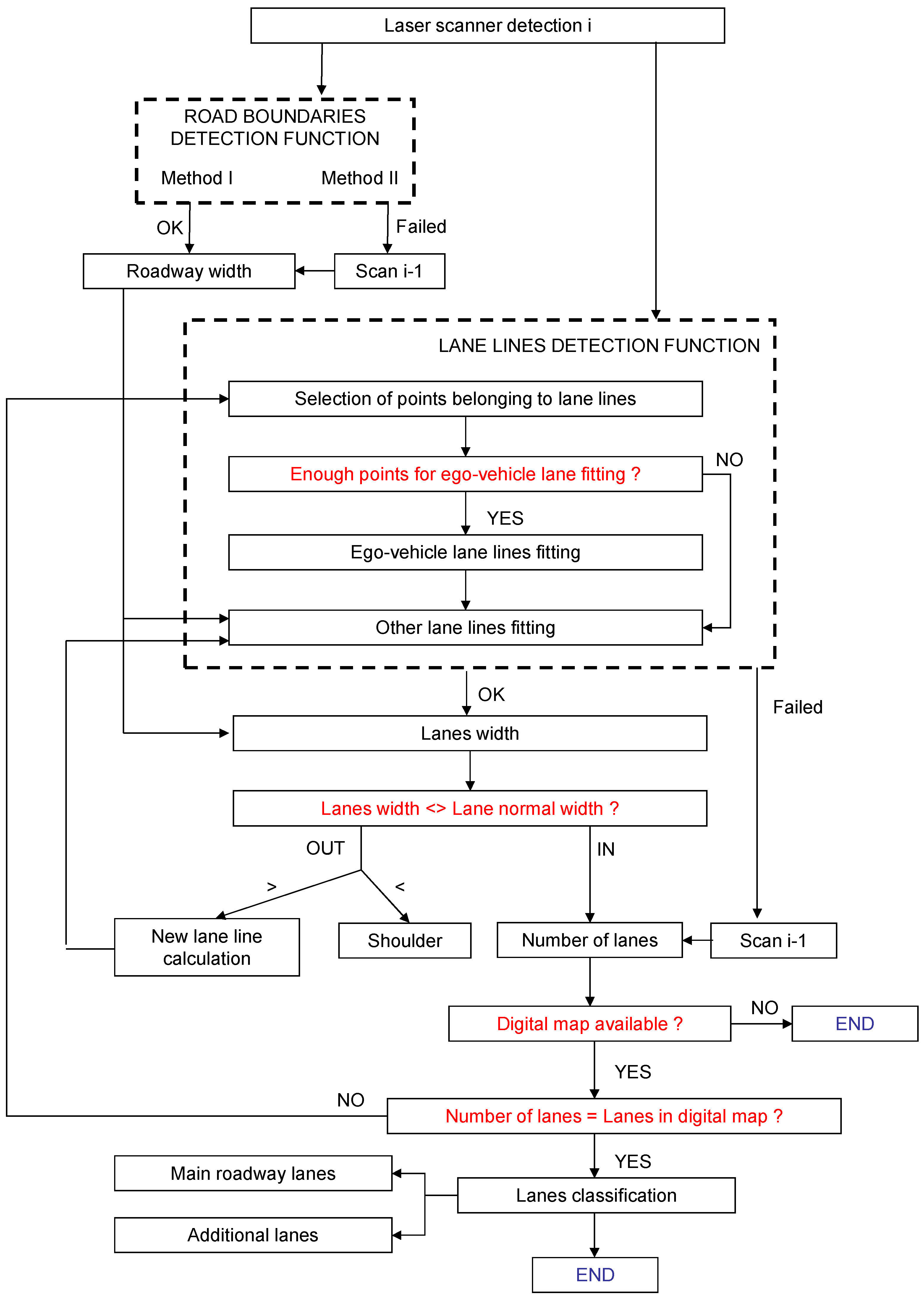
Figure 2.
Illustration for Method I for the detection of roadway boundaries.
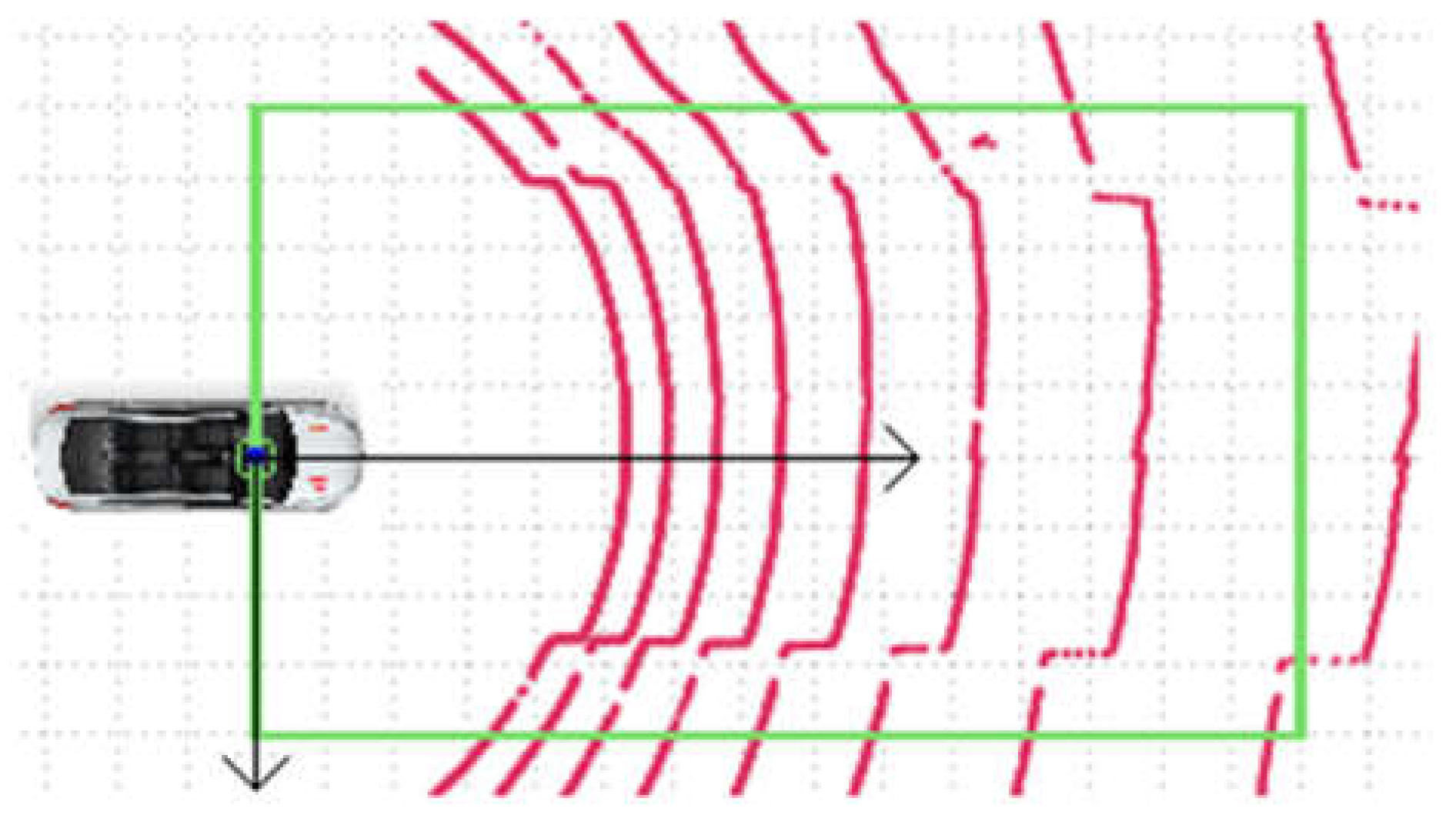
Figure 3.
Example of evolution of radius difference between 2 consecutive laser scanner layers in the roadway-sidewalk transition.
Figure 3.
Example of evolution of radius difference between 2 consecutive laser scanner layers in the roadway-sidewalk transition.

Figure 4.
Example of curve fitting to points of intersection of the layers of the laser scanner and the ground. (a) Total set of points (yellow); (b) Filtered points (red).
Figure 4.
Example of curve fitting to points of intersection of the layers of the laser scanner and the ground. (a) Total set of points (yellow); (b) Filtered points (red).

Figure 5.
Definition of points belonging to lane lines.

Figure 6.
Definition of regions of interest for grouping line sections. (a) Case of having enough information of each line section (areas marked in red); (b) Case of not having enough information on each of the sections (areas amrked in green).
Figure 6.
Definition of regions of interest for grouping line sections. (a) Case of having enough information of each line section (areas marked in red); (b) Case of not having enough information on each of the sections (areas amrked in green).

Figure 7.
Roadway detection using Method II. (a) Scenario; (b) Tridimensional detection of the laser scanner; (c) Function results (points belonging to the passable path inside the region of interest marked in green).
Figure 7.
Roadway detection using Method II. (a) Scenario; (b) Tridimensional detection of the laser scanner; (c) Function results (points belonging to the passable path inside the region of interest marked in green).

Figure 8.
Detection of passable areas in an off-road environment. (a) Scenario; (b) Three-dimensional detection of the laser scanner; (c) Function results (points belonging to the passable path inside the region of interest marked in green).
Figure 8.
Detection of passable areas in an off-road environment. (a) Scenario; (b) Three-dimensional detection of the laser scanner; (c) Function results (points belonging to the passable path inside the region of interest marked in green).

Figure 9.
Examples of situations of erroneous or uncertain detections. (a) Road shoulder detection; (b) Occlusions; (c) Loss of information of any of the lane lines; (d) Merging lane detection.
Figure 9.
Examples of situations of erroneous or uncertain detections. (a) Road shoulder detection; (b) Occlusions; (c) Loss of information of any of the lane lines; (d) Merging lane detection.


Table 1.
Comparison of roadway detection methods (analysis over 875 frames).
| Method I | Method II | |
|---|---|---|
| Correct detection with a range greater than 10 m | 28% | 94% |
| Correct detection with a range lower than 10 m | 67% | 2% |
| Incorrect detection | 5% | 4% |
Table 2.
Reliability in lanes detection.
| Scenario without Singularities (200 Frames) | Scenario with Singularities (700 Frames) | |
|---|---|---|
| Correct detection | 78% | >47% * |
| Calculation not performed | 8% | 18% |
| Incorrect detection | 14% | <35% * |
* Every case that involves a merging or exit lane detection is not considered as correct, because it is not possible to determine its nature, and it could be confused as an additional lane.
© 2018 by the authors. Licensee MDPI, Basel, Switzerland. This article is an open access article distributed under the terms and conditions of the Creative Commons Attribution (CC BY) license (http://creativecommons.org/licenses/by/4.0/).
Share and Cite
MDPI and ACS Style
Jiménez, F.; Clavijo, M.; Castellanos, F.; Álvarez, C. Accurate and Detailed Transversal Road Section Characteristics Extraction Using Laser Scanner. Appl. Sci. 2018, 8, 724. https://doi.org/10.3390/app8050724
AMA Style
Jiménez F, Clavijo M, Castellanos F, Álvarez C. Accurate and Detailed Transversal Road Section Characteristics Extraction Using Laser Scanner. Applied Sciences. 2018; 8(5):724. https://doi.org/10.3390/app8050724
Chicago/Turabian StyleJiménez, Felipe, Miguel Clavijo, Fernando Castellanos, and Carlos Álvarez. 2018. "Accurate and Detailed Transversal Road Section Characteristics Extraction Using Laser Scanner" Applied Sciences 8, no. 5: 724. https://doi.org/10.3390/app8050724
Note that from the first issue of 2016, this journal uses article numbers instead of page numbers. See further details here.