Improvement of the Torque-Speed Performance and Drive Efficiency in an SRM Using an Optimal Torque Sharing Function


School of Automation Science and Electrical Engineering, Beihang University, Beijing 100191, China
*
Author to whom correspondence should be addressed.
Appl. Sci. 2018, 8(5), 720; https://doi.org/10.3390/app8050720
Submission received: 16 April 2018
/
Revised: 26 April 2018
/
Accepted: 1 May 2018
/
Published: 4 May 2018
Abstract
:In this paper, by evaluating the extreme value of the qth-power current, a torque sharing function (TSF) family for reducing the torque ripples in the switched reluctance motor (SRM) is proposed. The optimization criteria of the TSF has two secondary objectives, including the maximization of the torque-speed range and the minimization of copper loss. The evaluation indices in terms of the peak phase current, the rms (root mean square) phase current, and the torque ripple factor are compared between the proposed TSF family and four conventional TSFs including linear, sinusoidal, exponential, and cubic TSFs. An optimization objective function that combines the maximum absolute value of the rate-of-change of the flux linkage (MAV-RCFL) and the qth-power of current is proposed and a weighting factor is used to balance the influence of the two optimization objectives. An optimal TSF can be easily obtained by solving the optimization problem from the TSF family. The proposed TSF is validated by using simulations and experiments with a three-phase 6/4 SRM with 7.5 kW, 3000 rpm, and 270 V DC-link voltage. The dynamic simulation model is implemented in Matlab/Simulink. The results demonstrate the validity and superiority of the proposed control method; the optimal TSF provides better torque-speed performance, and a better reduction in copper loss and torque ripples at high speed, as compared to conventional TSFs.
1. Introduction
Switched reluctance motors (SRMs) are gaining interest in various applications such as electric vehicle driving system, starter-generators system, and power supply for aerospace applications, because of the many advantages that the SRMs have in comparison to other motors, including their low cost, durability, simple structure and robust construction [1,2]. Due to advances in high speed digital signal processing and power electronics technology, the controllable performance of the SRM has been improved greatly. However, one of the main drawbacks of the SRM used in servo-control is its large torque ripple, which leads to acoustic noise and vibration, thus causing the body vibration, transmission system parts damage, excessive bearings wear and even accidents involving the axis breaking [3,4].
There are two main methods to reduce the torque ripple: one is to optimize the structure and magnetic design of the motor, and the other is to adopt the advanced control algorithm [5]. By optimizing the stator/rotor pole structures and the magnetic design, the torque ripple cannot be fully reduced, but the cost of the motor increases [6]. The main operating parameters of an SRM include the supply voltage, the turn-on and turn-off angles, the current level, and the shaft torque. And the control algorithm is based on selecting an optimum combination of these parameters [7,8]. Therefore, an appropriate design for achieving a high SRM performance must take these factors into consideration and make an optimal choice.
As an effective method for torque ripple reduction, direct instantaneous torque control (DITC) has gained interest in the last few years, due to its simple control structure, which provides greater flexibility for the torque ripple reduction [9,10,11,12]. However, its implementation is not easy because it requires complex switching rules, uncontrolled switching frequency, and high sampling rates. In [9,10], an iterative learning method for generating the optimized current waveforms was presented. In [11,12], an online DITC technique that operates without torque profile functions and auxiliary phase commutating strategies was demonstrated. The optimal turn-on and turn-off angles for minimizing the torque ripple or the energy consumption has been described in [13,14,15]. In [16], a direct torque control based on the Lyapunov function was selected to minimize the torque ripples. In [17,18], the machine design was combined with the control algorithms in an innovative method of profiling the phase currents to reduce the torque ripples of an SRM.
In the latest research, the torque sharing function (TSF) has been investigated as an important and effective approach for minimizing the torque ripple in an SRM [19,20,21,22,23,24]. Common TSFs curves contain linear, sinusoidal, exponential, cubic curves, and so on. In order to reduce the torque ripple, the phase current product and the individual phase torque harmoniously use the most suitable TSFs so that the total torque can align with the expected torque. Subsequently, the phase torque reference can be translated into the phase current reference based on the T-i-θ characteristics. With increasing speed of the SRM, the phase current cannot ideally follow its reference because of the limited phase voltage and therefore the torque ripples increase. In addition, because the phase current reference can be derived from the phase torque reference, the choice of the TSF directly affects the copper loss and the current tracking performance. The current tracking performance should be improved to enhance the torque-speed capability. Thus, in order to obtain an optimum TSF, it is necessary to consider a secondary objective that includes the maximization of the torque-speed range and the minimization of copper loss. These two evaluation criteria affect the torque-speed performance and the drive efficiency of the motor. In [19], four conventional common TSFs were studied and evaluated after optimization. In order to minimize the rms (root mean square) phase current and the maximum absolute value of the rate-of-change of the flux linkage (MAV-RCFL), the turn-on and the overlap angle were extracted based on a genetic algorithm optimization method to select the optimal TSF. In [20], for reducing the losses of the switched reluctance motors, a piecewise cubic TSF was optimized with six degrees of freedom. In [21], an offline TSF with a wide torque-speed range for reducing torque ripple in an SRM was studied; the objective function adopted a Tikhonov factor among two objectives to minimize the maximum absolute value of RCFL and the copper loss. In [22], an extended-speed low-ripple torque control in two modes using the TSF in an SRM was introduced. Because of the imperfect tracking of the phase current in high motor speed, a proportional-integral controller with a torque-compensation was added to the torque reference during the commutation range of two adjacent phases. In [23], a novel and simple nonlinear logical TSF was proposed to reduce the torque ripple and improve the efficiency. The logical TSF was used online and was not fixed compared with the other TSFs. The incoming phase current was controlled in a ladder-like increase, and the current of the outgoing phase was tracked in the opposite direction. Therefore, torque sharing between the incoming and outgoing phases was achieved with a minimum current crossover. However, a theoretical analysis of the RCFL was not provided for this study.
In this paper, taking into account the requirements for the maximization of the torque-speed range and the minimization of copper loss and balancing these secondary objectives by including a weighing factor, a family of TSFs deduced by an invertible torque function is proposed. Because the proposed TSF provides phase currents throughout the whole region, the torque-speed capability is improved as well. The solution of the TSFs selection becomes a multi-objective optimization problem. And then, the evaluation indices such as the peak phase current, the rms phase current, and the torque ripple factor are compared between the proposed and the classical TSFs by using a simulation. Finally, the simulation and experimental results show that the proposed control algorithm has advanced performance in reducing the copper loss and improving torque-speed performance.
2. The Finite Element Method Analysis for the SRM
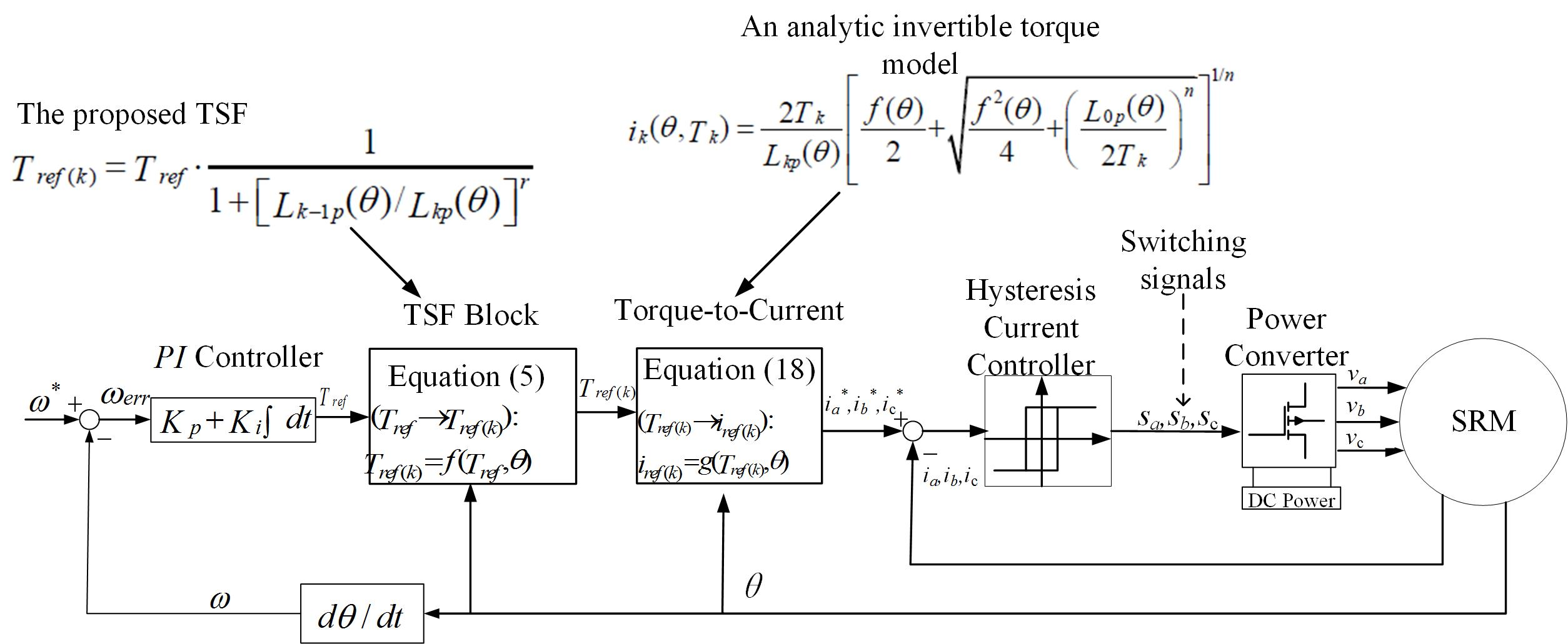
The SRM only has stator windings, no rotor windings or magnets. The whole or part of each phase is comprised of two stator windings on diametrically opposite sides of the SRM. A three-phase 6/4 SRM with 7.5 kW, 3000 rpm, and 270 V DC-link voltage is designed (seen Table A1 in Appendix A). Figure 1a–d shows the analysis model of the studied motor using the finite element method (FEM) with the magnetic flux at rotor positions of 0°, 15°, 30°, and 45° respectively. The anti-clockwise is the positive direction of the rotor angular position θ and the alignment position of the stator and rotor poles is defined as 0°.
In practical SRM analysis, the non-linear characteristics and the electromagnetic analysis of the SRM are important. By using ANSOFT/Maxwell software (ANSOFT/Maxwell 14.0, Ansys Inc., Canonsburg, PA, USA), the flux linkage, the phase inductance profiles and the torque characteristics of the studied SRM were analyzed. And the results are shown in Figure 2a–c. Due to the saturation effect, the maximum value of the phase inductance decreases with the increase of the current. In Figure 2b, the flux linkage characteristics demonstrate the saturation effects. The lowest curve corresponds to a 0 A phase current and the top of the curve to an 8 A phase current. The torque generated by a constant current and a ±45° in the phase-A winding is shown in Figure 2c and is the same as the other phases. The phase torque has nonlinear properties which strongly depends on the phase current values and the rotor position. It is significant that the phase torque decreases when the rotor position is near the alignment position of the stator and rotor poles. This is caused by the saturation effect, which leads to a decrease in the derivative of the co-energy to the rotor position. This, in turn, causes the large torque ripple of the SRM, which requires a complex control strategy to reduce. As shown in Figure 3a,b, the linear interpolation resulted in a surface fitting and this linear interpolation approach can be used for other non-test states to obtain the necessary data for the flux linkage and the torque for any given value (i, θ).
3. Theoretical Background of the SRM
3.1. Torque Generation
The principle of the torque generation in an SRM is based on the reluctance minimization of the magnetic flux linkage paths. Each phase, the torque strongly varies with the phase current and rotor position variation. Generally, the torque phase Tk can be calculated from the co-energy as follows:
where k is the identifier of the phases, θ is the rotor position, ik is the phase current, and Ψk is the phase flux linkage. All of the position angles refer to mechanical angles (except where noted). The two basic equations that describe each phase flux linkage and the machine model of the SRM are as follows:
where Lk is the kth phase inductance, uk is the kth phase instantaneous voltage, and R is the phase winding resistance. Because of the highly nonlinear and saturation effects of the electromagnetic characterization in the SRM, the inductance Lk in Equation (2) varies not only with phase current value but also with rotor position variation.
By neglecting the saturated nature, we simplify the formula and assume that the inductance Lk varies only with the rotor position θ. According to Equations (1) and (2), the torque Tk can be expressed as:
where Lkp is denoted as the derivative of Lk. In this case, assuming that Lkp is known, Equation (4) enables a fast and simple torque calculation.
3.2. TSFs
To minimize the torque ripple, the commonly used TSFs can be classified as linear, sinusoidal, exponential, and cubic and their details have been reported in [19,24]. Through the torque control with a TSF in the region where it shares the torque with one or more phases (called the commutation or overlap region), the total torque reference Tref is divided into separate torque reference Tref(k) for each phase. According to the characteristics of the torque-current-position, the Tref(k) is converted into the phase current reference ik with respect to the rotor position information.
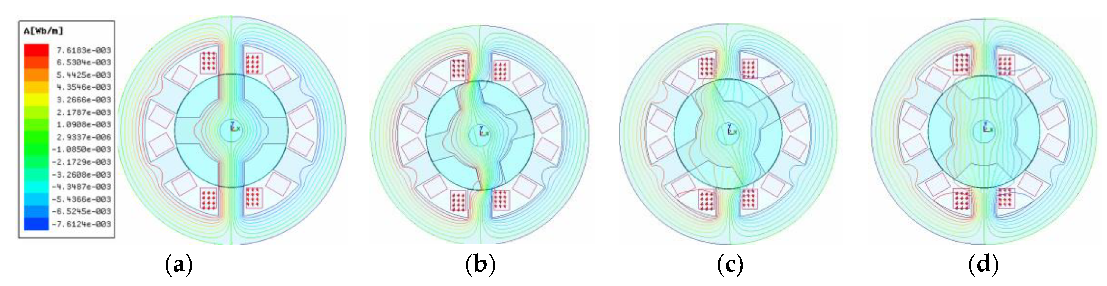
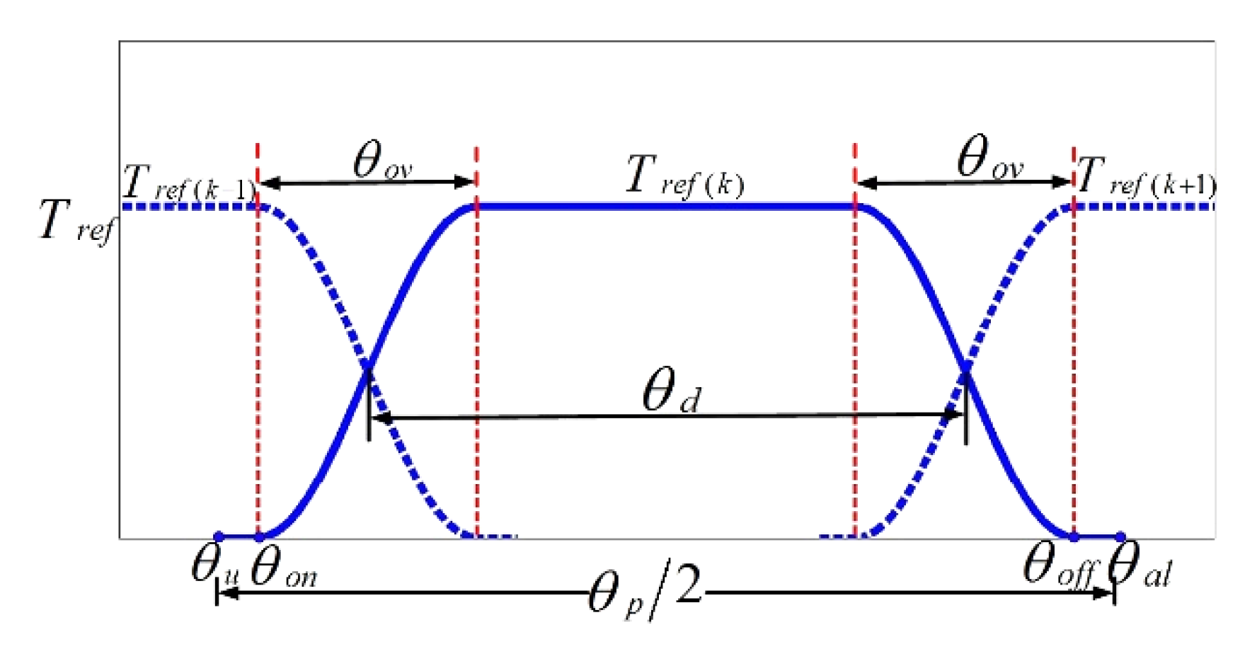
Figure 4 shows an illustration of a TSF. The kth phase torque reference denoted as Tref(k) is calculated as:
where θu, θon, θov, θoff and θal are the unaligned, turn-on, overlap, turn-off and aligned angles, respectively; frise(θ) and represents the ascending area and ffall(θ) represents the descending area in the TSF. In the commutation region, frise(θ) must increase from 0 to 1 and ffall(θ) must decrease from 1 to 0. For any TSF, the function ffall(θ) that is relevant to frise(θ) can be computed as follows:
The angle θp = 2π/Nr denotes the rotor pole pitch, where Nr is the number of rotor poles. And θd = 2π/(mNr) denotes the angular displacement between the neighboring phases. In the case of a normal SRM commutation, these angles have the following relationships:
Thus, we can get θp = 90°, θd = 30°, and θov ≤ 15° from Equations (7) and (8) in the three-phase 6/4 SRM. For the four-phase 8/6 SRM, we have θp = 60°, θd = 15°, and θov ≤ 15°.
4. Evaluation Criteria
4.1. The MAV-RCFL
The MAV-RCFL is easily obtained from Equation (3). At a steady state of non-zero angular speed and neglecting the phase resistance, Equation (3) can be represented as follows, where Vdc is the phase DC-link voltage:
It is evident that the MAV-RCFL depends on the phase DC-link voltage Vdc and the rotor angular speed ω with respect to the position θ. That means that, for a given Vdc, the flux linkage derivatives dΨk/dθ can estimate the rotor speed range, at which the torque-speed performance theoretically allows a torque-ripple-free operation. It can be seen from Equation (9) that the maximum absolute value of dΨk/dθ limits the maximum speed range ωmax. The MAV-RCFL denoted as MR is defined as:
According to Equations (9) and (10), the maximum speed range ωmax for operating torque ripple performance freely must satisfy the following:
To be specific, the smaller the maximum MR, the larger the maximum rotor speed ωmax is. In other words, the MAV-RCFL is expected to be as small as possible.
4.2. Copper Loss
Total losses in an SRM include iron loss and copper loss and the latter represent the major component of the losses. Thus, the copper loss directly influences the torque-speed performance and the drive efficiency. And the copper loss is in direct proportion to the square value of the rms phase current Irms, which is calculated from:
Since in the region θon + θov ≤ θ ≤ θoff − θov, the kth phase produces the total torque independently as shown in Figure 4 and minimizing the rms phase current Irms can be realized by decreasing the second part of Equation (12).
Hence, by modifying Equation (12), an optimization objective function can be expressed as follow:
where q is a bound variable satisfied q ≥ 2. In Equation (13), the qth-power of the current is a substitute for the integration of the averaged square value of the current during the commutation.
A torque reference profile can now be generated for a specific TSF. The current profile and the flux linkage profile are obtained using the given torque and flux-linkage characteristics. Hence, the MAV-RCFL and the square value of the rms current can be computed. As discussed above, by optimizing the TSFs, a wide rotor speed range and less copper loss can be obtained by minimizing the MAV-RCFL and the square value of the rms current. This is the basic principle and direction for selecting an optimal TSF.
5. Proposed TSFs
5.1. Evaluation Function for the Choice of Proposed TSF
An evaluation function that combines MAV-RCFL MR and the qth-power of current J1 with a weighting factor is proposed as:
where wf is the weighting factor satisfied 0 ≤ wf ≤ 1. and are the normalized values of J1 and MR respectively and they can be computed from = J1/J1,max and = MR/MR,max, where J1,max and MR,max are the maxima of J1 and MR respectively.
When wf = 1, the e evaluation function only consists of the square value of the rms current. In this case, the minimum copper loss is the only optimization objective. When wf = 0, the maximum speed range is the only optimization objective. When 0 < wf < 1, both maximum speed range and minimum copper loss at different proportions are considered as the optimization objectives in order to obtain the correct balance.
5.2. A Family of TSFs
According to the definition of a TSF from Equations (5) and (6), the phase torques produced by the currents ik(θ) and ik−1(θ) in Equation (13) share the total torque reference in the commutation region, which are denoted as Tref(k) (θ) and Tref(k−1) (θ) = Tref − Tref(k) (θ). Thus, by neglecting the saturated effects, Equation (13) can be rewritten from Equation (4) as:
When dJ1/dTref(k) = 0 to obtain the extreme value of J1, the desirable TSF calculated from Equation (15) is depicted as:
where r = q/(q − 2) is an undetermined constant, satisfied by r ≥ 1. Tref ×frise(θ) in Equation (5), which is defined by the right part of Equation (16) and the other section of TSF can then be easily obtained from Equation (6).
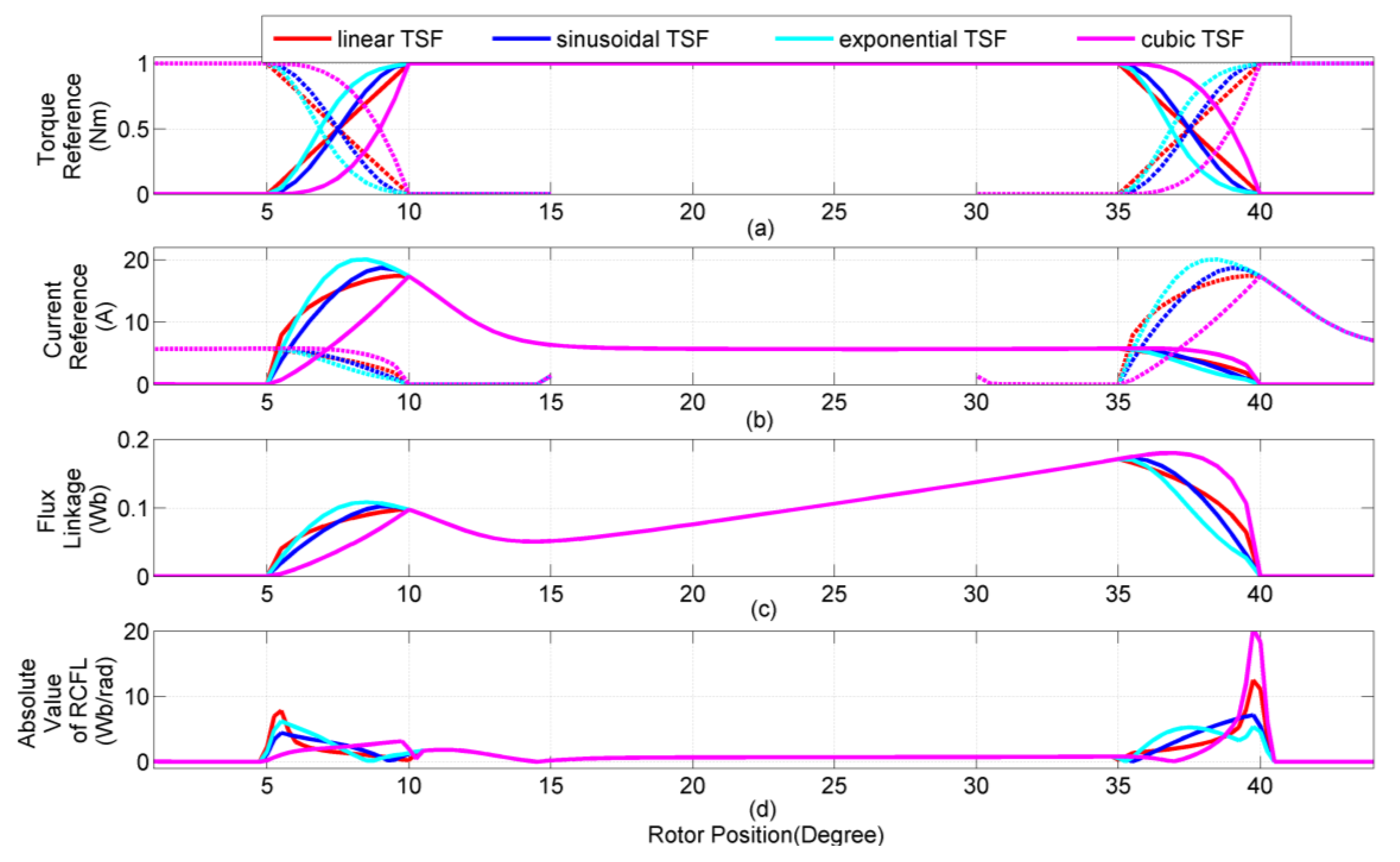
5.3. Comparison of the Conventional and Proposed TSFs
Figure 5 shows the typical profiles of four common conventional TSFs [25]. The turn-on angle, turn-off angle, and overlap angle, θon, θoff, and θov are set to 5°, 40° and 5°, respectively. And the torque reference Tref is set to 1 Nm. In Figure 5a–d, the profiles (top to bottom) are the torque reference, the current reference, the flux linkage reference, and the absolute value of RCFL respectively. From Figure 5d, the values of MR for the linear, sinusoidal, exponential, and cubic TSFs are 11.78, 6.75, 5.05, and 19.10 Wb/rad, respectively. According to Equation (11), the values of maximum rotor speed ωmax for a torque-ripple-free operation of four common conventional TSFs are 22.9, 40, 53.5, and 14.1 rad/s, which are equal to only 219, 382, 511, and 135 rpm, respectively.
Figure 6a shows the change in the MAV-RCFL with the changing torque reference, indicating that the exponential TSF resulted in the lowest RCFL value. The peak values of the reference currents at each torque reference are compared in Figure 6b showing an increase in the currents as the torque reference increases. The peak current is the same for the linear TSF and the cubic TSF and it is lower than for the other two TSFs. This indicates that the power converter has much smaller pressure and better insulation for the linear and cubic TSFs. The rms currents at each torque reference are compared in Figure 6c, which indicates that the linear and the sinusoidal TSFs have almost the same value of rms current at the torque reference between 0.5 Nm and 3 Nm. The rms current is lower for cubic TSF than for the other TSFs.
In summary, if the minimum MR (when wf = 0 in Equation (14)) is the only optimization target, the best choice of TSF is the exponential TSF, the second best choice is the sinusoidal TSF, and the worst choice is the cubic TSF. On the other hand, if the minimum copper loss J1 (when wf = 1 in Equation (14)) is the only optimization objective, the cubic TSF represents a good choice, and it also has the lowest value for the peak current.
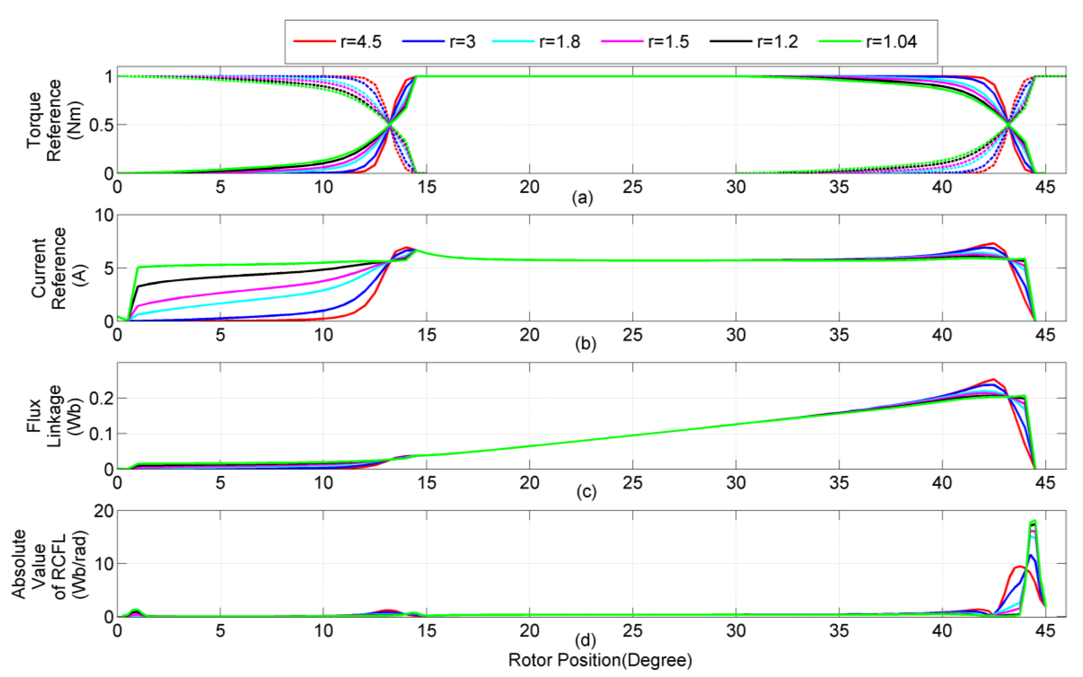
Figure 7a–d show the typical profiles of several proposed TSFs for different r values. From Figure 7, when r tends to ∞, the minimization of the copper loss is achieved theoretically because the torque reference tends to be zero during the commutation region. By decreasing r, the torque reference increases during the commutation region, which results in an increase in the rms phase current. When r tends to 1, Figure 7b shows that the phase current reference of two adjacent excited phases in the commutation region is equal. And it is clear that the peak value of phase current is also the smallest when the TSF is defined by r → 1.
Figure 8a shows the relationship between the MAV-RCFL and the exponent r. As MR reaches its minimum at r ≈ 4, it is reasonable to choose r = 4 as the exponent of the optimal TSF in Equation (16). When Tref is set to 1 Nm and Vdc is set to 270 V in the case of r = 4, the maximum speed range ωmax for operating torque ripple performance freely can be achieved at 30 rad/s, which is equal to 286.6 rpm. The equivalent level of the linear and the cubic TSFs are also marked with the dash-dotted line in the Figure 8a–c for comparison. Figure 8b shows the peak phase current reference as a function of the exponent r. If r is larger than 3.5, the peak phase current exceeds the theoretical minimum value of 6.65 A by more than 5%. In Figure 6b, the minimum peak current values of the four common conventional TSFs are about three times higher than the values of the proposed TSFs. The rms phase current reaches a theoretical minimum value of 3.5 A when r ≥ 3 from Figure 8c. Assuming a torque reference of 1 Nm, the rms current values are larger for the four common conventional TSFs than for the proposed TSFs at any value of r (Figure 6c).
Therefore, the TSF with the minimum MR value at r = 4, denoted as TSF1 (r = 4), should be used as the optimal value at higher speed because it provides smaller peak phase current and lower copper loss relatively.
6. Nonlinear Mathematical Model of Torque Profile
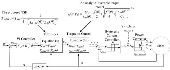
The optimal TSF is obtained by solving the optimization problem in Equation (14). However, Equation (4) is utilized to approximate the phase torque based on a linear relationship between the phase flux linkage and the current as shown in Equation (3). An analytic invertible torque function that represents the nonlinear and saturation effects appropriately was used as follows [26]:
where Lkp(θ), f(θ) and n are the undetermined parameters that are dependent on the rotor position and the motor parameters.
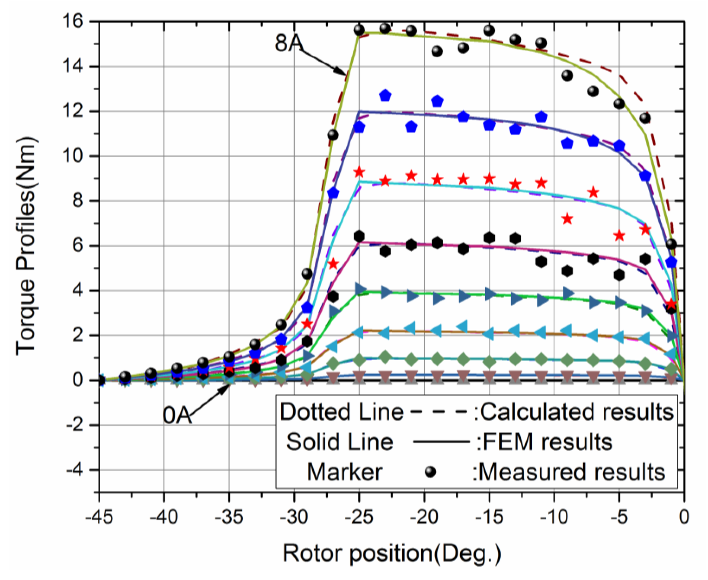
As shown in Figure 9, by choosing reasonable parameters for Lkp(θ) and f(θ), the characteristics of the torque-current-position obtained from Equation (17) agree well with those using FEM or those from experimental measurements. After rejecting the improbable solution, the current reference can be rewritten as Equation (18) by inverting the torque equation in Equation (17) as follows:
The data of the two angular functions Lkp(θ) and f(θ) stored in the digital controller can be used to calculate the current reference according to Equation (18), instead of using the 3-D lookup table of T-i-θ.
7. Simulation Results and Comparison
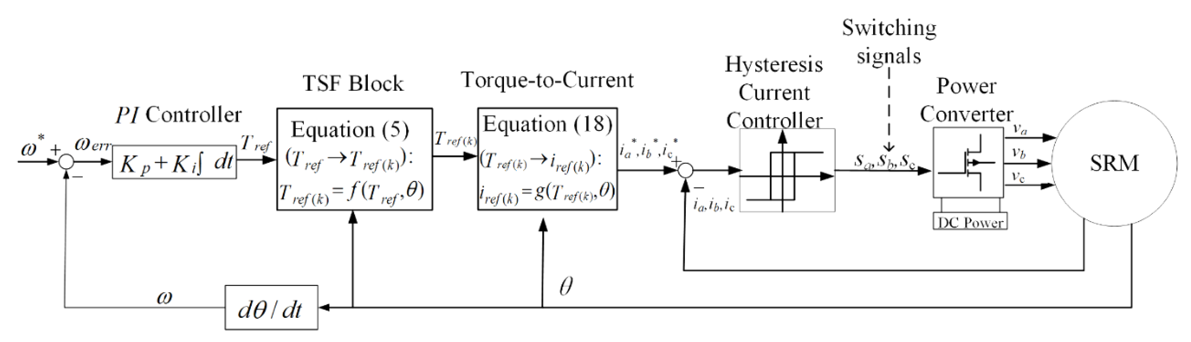
Figure 10 shows the block diagram of the torque control using the TSF method for the studied SRM. The individual phase torque reference is defined from the total torque reference by the TSF block. In the “Torque-to-Current” block, the phase torque references are converted into phase current references the rewritten torque-current profile model of the SRM (Equation (18)). A hysteresis current controller is used for the phase current tracking its reference waveforms.
Matlab/Simulink was used to for the simulation model of the three-phase 6/4 SRM with 7.5 kW, 3000 rpm, and 270 V DC-link voltage by using the static torque characteristic profiles shown in Figure 9 and obtained using Equation (17). For the phase current tracking its reference waveforms accurately, it is appropriate to set the hysteresis band of the current controller to ±0.1 A through simulation test. The phase current reference is calculated using Equation (18). The same sampling time tsample = 1 μs is set in all simulation. Finally, the evaluation indices in terms of peak phase current, rms phase current, and torque ripple factor are compared between the proposed and the classical TSFs.
The torque ripple factor is defined as follows:
where Tmax, Tmin, and Tave are the maximum, minimum, and average torque, respectively.
7.1. Simulation Results
The CCC (current chopping control) method is common in SRM control and was investigated in [27]. The simulation results for the proposed TSF1 (r = 4) are compared with the CCC and the conventional TSFs at a torque reference Tref = 1.5 Nm and a rotor speed of 1000 rpm (Figure 11a–d). Since the rotor speed 1000 rpm of all TSFs is higher than the maximum rotor speed ωmax, the phase current cannot track its reference. The torque ripple factors T.R% for the CCC, the linear, sinusoidal, and the proposed TSFs are 116.7%, 28.7%, 22.0%, 23.5%, respectively. The rms currents are 3.5 A for the linear and sinusoidal TSFs, and 3 A for the TSF1 (r = 4).
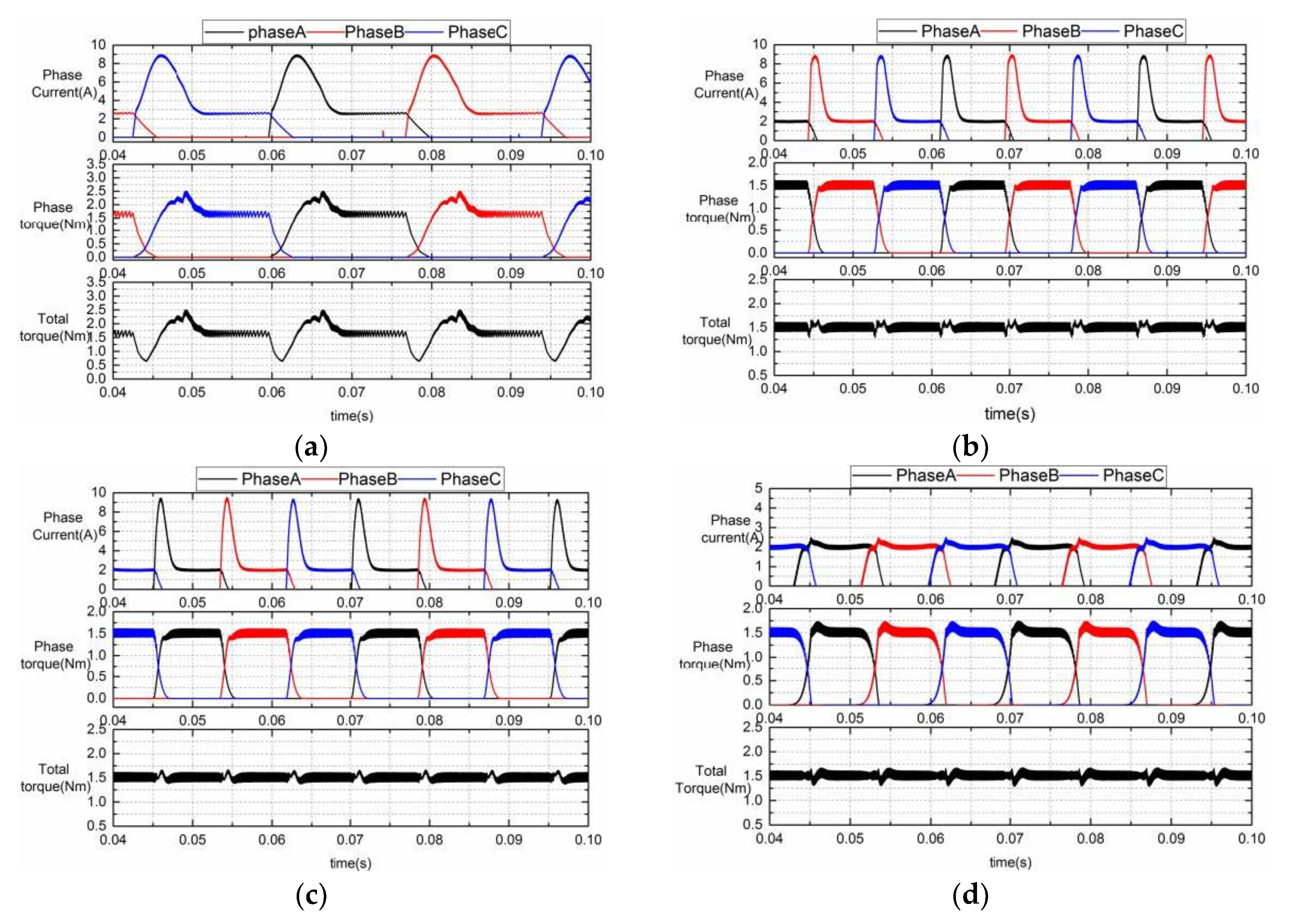
The simulation results for the CCC, the linear, the sinusoidal, and the proposed TSFs at a torque reference of Tref = 1.5 Nm and a speed of 3000 rpm are shown in Figure 12a–d. As the rotor speeds up, the phase current deviates from its reference significantly during the current rising region. And the phase current exhibits a tail phenomenon at the same time during the current declining region. Therefore, the output torque cannot track its reference accurately and the torque ripple increases obviously. The torque ripple factors T.R% are 182.3%, 61.3%, 60.8%, and 36.6%, respectively. For the CCC, the linear, the sinusoidal, and the proposed TSF1 (r = 4), the peak phase currents are 8.8 A, 9.4 A, 9.5 A, and 5.5 A, and the rms phase currents are about 5.4 A, 5.4 A, 5.3 A and 3.8 A, respectively. It is evident that the CCC method results in a comparatively smaller peak phase current compared with the conventional TSFs. However, the torque ripple is not acceptable, because it is three times higher than that of the proposed TSF1 (r = 4). The linear and sinusoidal TSFs almost have the same performance with regard to the torque ripple and the peak phase current, which is approximately twice as high as those for the proposed TSF1 (r = 4). The proposed TSF1 (r = 4) results in the lowest torque ripple, which is 1/2 of the torque ripple of the linear TSF. In addition, the required phase current is lower than for the CCC. The control performance is clearly improved by using the proposed TSF1 (r = 4).
7.2. Comparison of the Simulation Results
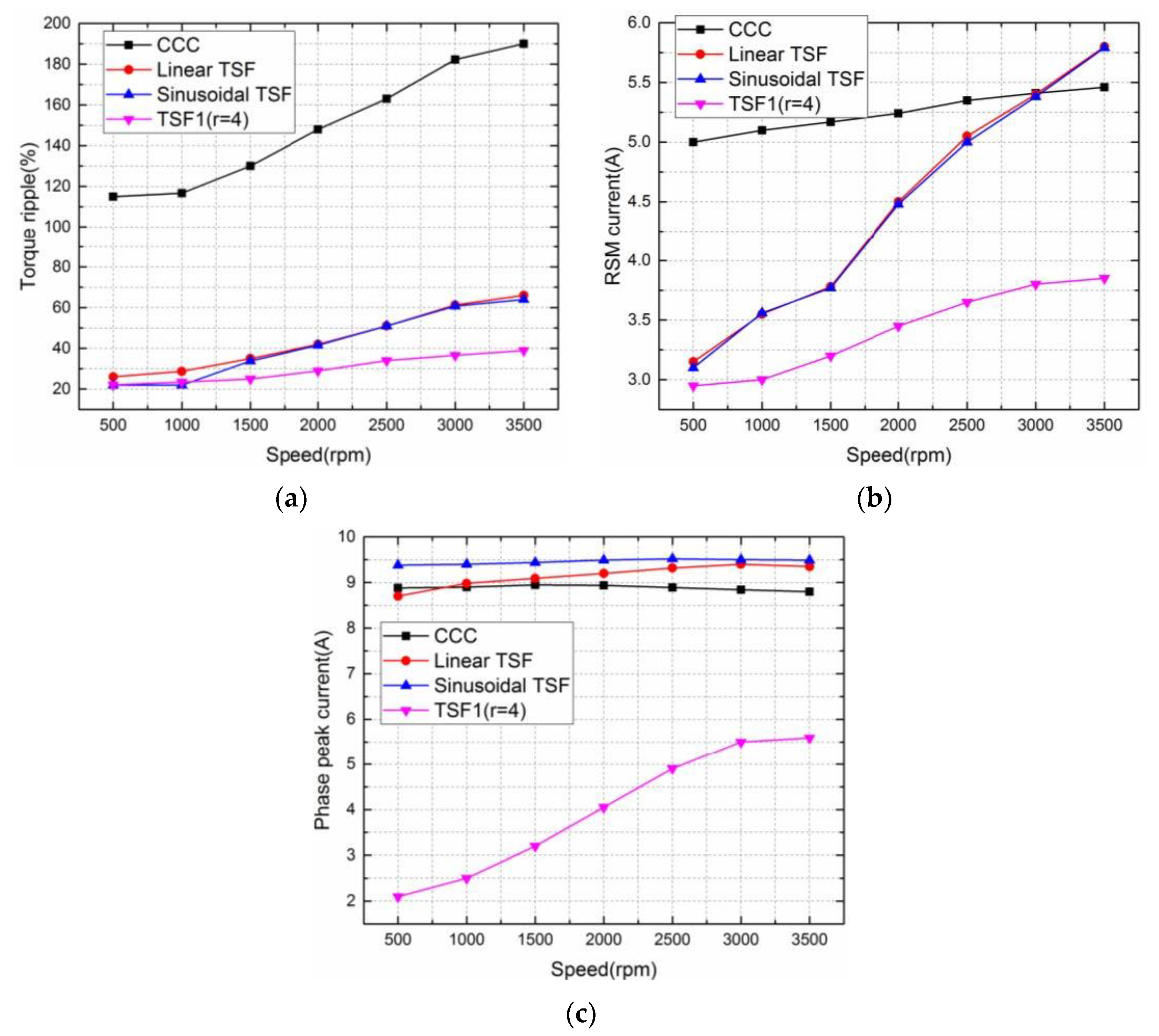
Figure 13a shows the comparison results of the torque ripple between the CCC, the linear, the sinusoidal, and the proposed TSF1 (r = 4) when the torque reference is set to 1.5 Nm. The CCC is the worst choice in all methods. For the conventional TSFs, the torque ripples are almost two to three times higher at 3000 rpm than at 1000 rpm. And at 3000 rpm, the torque ripple of the proposed TSF1 (r = 4) is nearly one half of the other TSF methods. That means the proposed TSF1 (r = 4) have a better performance than the other control method. Actually, at a lower rotor speed, the torque ripple of the proposed TSF is obviously affected by the hysteresis band of the current controller. Therefore, the torque ripple can be decreased further more by reducing the inherent current ripple of the hysteresis controller.
Figure 13b shows the comparison results of the rms current for all control methods and the CCC is also the worst choice. At the rotor speed less than 500 rpm, the proposed and the conventional TSFs exhibits almost a similar rms current. As the rotor speeds up, due to the poorer current tracking performance, the rms currents of the linear and sinusoidal TSFs increase significantly. However, the rms current for the proposed TSF remains relatively as the speed increases.
The peak current is much smaller for the TSF1 (r = 4) than those of the other methods, which have smaller hardware pressure (Figure 13c). At a higher speed, the peak currents of the conventional TSFs decrease significantly due to the poorer current tracking performance by the inductance effect. Therefore, the TSF1 (r = 4) is a better choice for reducing torque ripple and lower copper loss relatively.
Figure 14a,b show the values of the evaluation function J for different weight factors wf at speeds of 1000 rpm and 3000 rpm. It is evident that the linear TSF is the worst choice because its J values are always much larger than those of the other TSFs at any weighting factor. The sinusoidal and cubic TSFs have almost the same J values at a speed of 1000 rpm. However, as the weight factor wf value increases, the cubic TSF exhibits a better performance. So, the choice of weight factor wf is depended on the emphasis of reducing the copper loss or increasing the maximum speed range. At any weight factor wf or any speed, the proposed TSF1 (r = 4) has the best minimum J values when compared to the sinusoidal or cubic TSFs.
8. Experimental Results
The proposed TSF is validated with an experiment using a three-phase 6/4 SRM with 7.5 kW, 3000 rpm, and 270 V DC-link voltage (shown in Figure 15). A Texas Instruments (TI) TMS320F2812 digital signal processor (DSP) is used as a digital controller, and the clock frequency of TMS320F2812 is 150 MHz. The T-i-θ characteristics are stored as look-up tables in the DSP. The SRM is driven by a three-phase asymmetric inverter and the motor shaft is coupled with a torque-speed sensor and position sensor. The three-phase asymmetrical inverter uses the six-cell IGBT module of Infineon Corporation. The type of IGBT is FS450R12KE4 (withstand voltage 1200 V, normal current 450 A). The driving chip of the three-phase bridge uses the 6SD312EI (working frequency is up to 100 kHz) produced by CONCEPT Corporation in Switzerland. There is one current sensor on each phase line. A synchronous generator with a resistance box is used as the load.
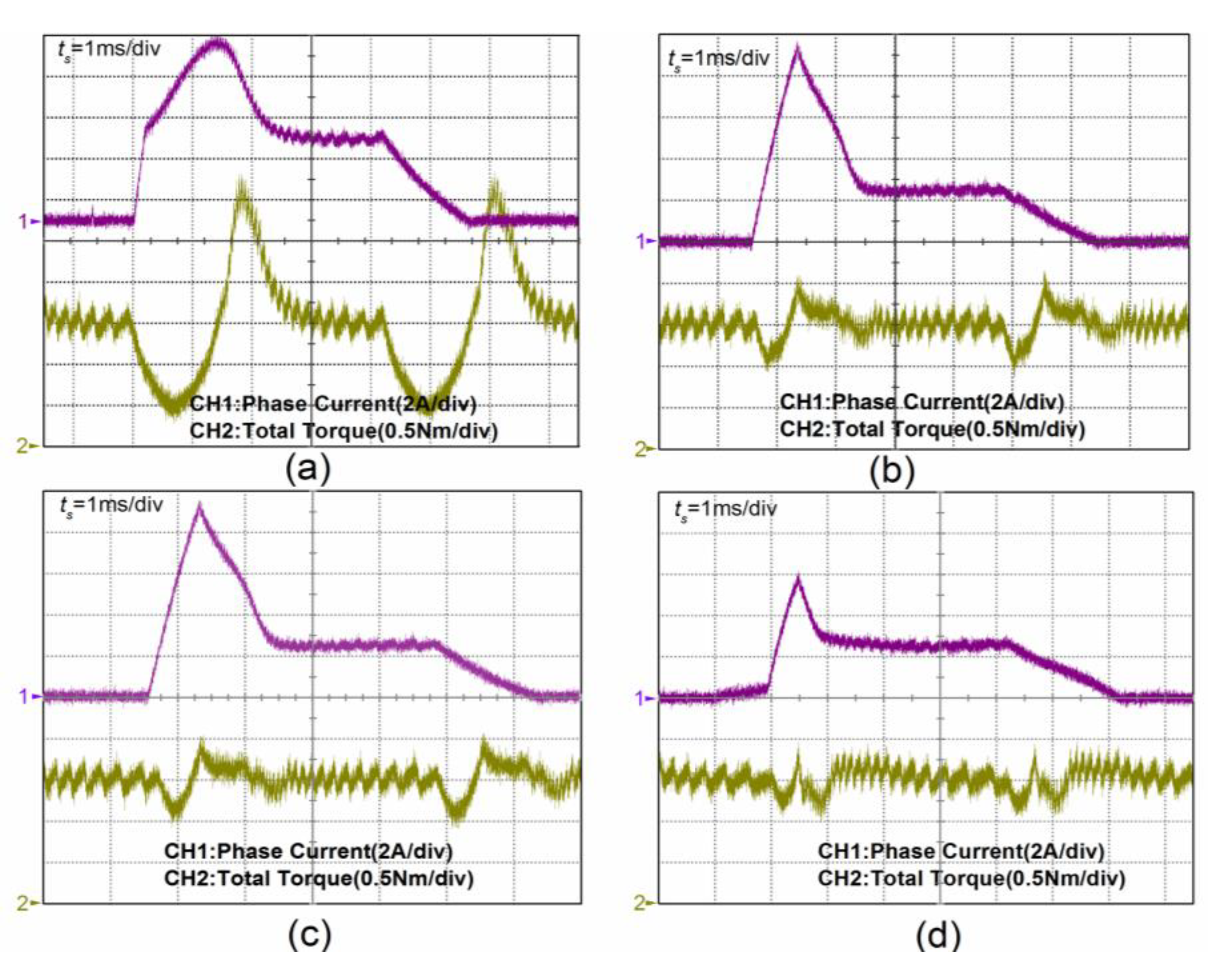
Figure 16 shows the measured phase current and instantaneous torque at 3000 rpm at a torque reference of Tref = 1.5 Nm. For the CCC, the linear TSF, the sinusoidal TSF and the proposed TSF1 (r = 4), the torque ripples are around 184%, 67.8%, 66.7%, and 40.4%, respectively compared to the values of 182.3%, 61.3%, 60.8%, and 36.6% in simulation results shown in Figure 12. And the peak phase currents are 8.9 A, 9.5 A, 9.5 A, and 5.9 A, and the rms phase currents are about 5.6 A, 5.4 A, 5.4 A and 3.9 A, respectively. This indicates that the experimental results agree well with the results of the simulation in terms of current waveforms, torque ripple and torque response under the same operating conditions. Due to a current tracking error, the CCC and the conventional TSFs show much higher torque ripples compared to the TSF1 (r = 4), which achieves better tracking and has a nearly flat output torque, ignoring the torque ripple caused by the inherent current ripple of the hysteresis controller.
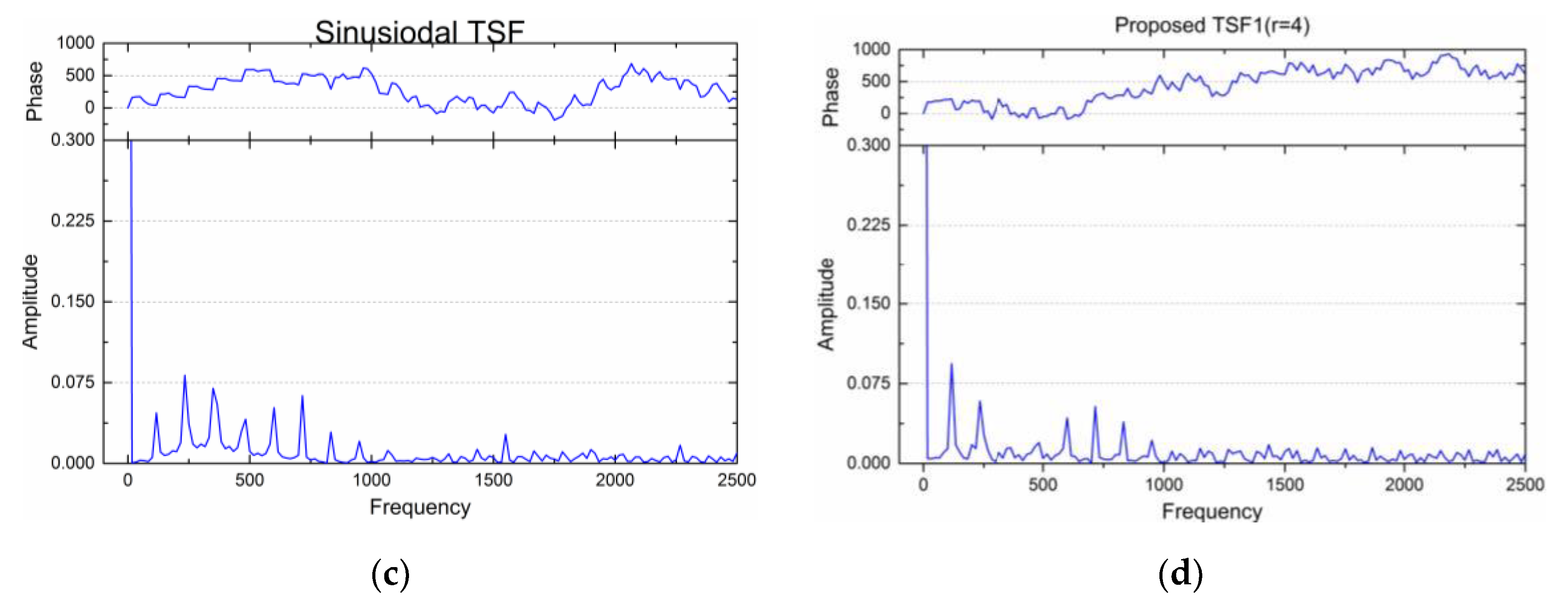
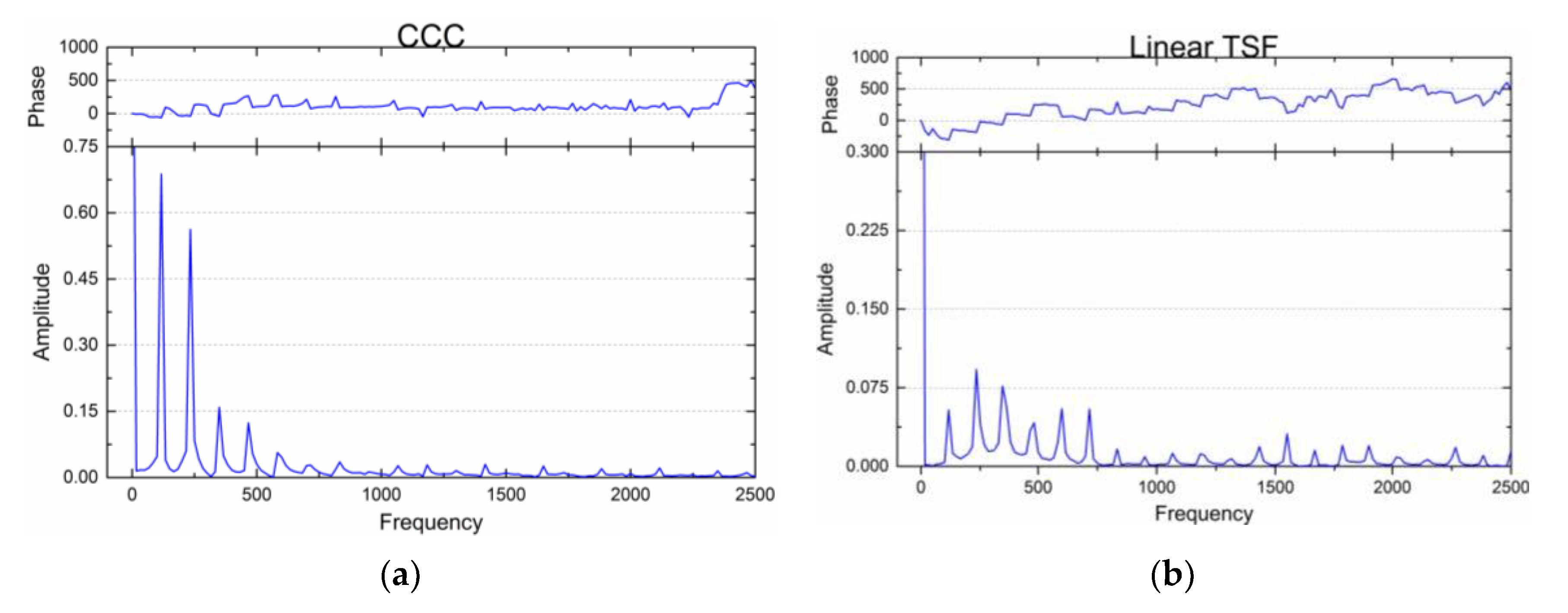
Assuming the total electromagnetic torque T is periodic when the actuation current is constant or position-periodic, the total torque T can be extended using a Fourier series as follows:
where N = 3 for the three phases of the 6/4 SRM. Figure 17a–d depicts the Fourier analysis of the experimental results of the total torque shown in Figure 16; the units for the phase and amplitude on the y-axis are rad and Nm, respectively. It is evident that the harmonic component of the proposed TSF1 (r = 4) is the least. Thus, the results of the simulation and experimental prove that the torque-speed performance and the drive efficiency are significantly improved by using the proposed TSF.
9. Conclusions
In this paper, based on the modified optimal criteria with the torque-speed performance and the drive efficiency, a computational procedure for the optimization model of a TSF has been described, including the maximization of the torque-speed range and the minimization of copper loss. In addition, by modifying the optimization objective of the qth-power current, a TSFs family with regard to torque capability is presented and the proposed TSF1 (r = 4) is compared with the conventional TSFs. The torque reference can be directly converted into the current reference using the rewritten torque-current profile model of the SRM either in the linear or the saturation magnetic region. The evaluation indices and the performance of the proposed and the classical methods are compared in terms of peak phase current, rms phase current, and torque ripple factor. The experimental results, which match the simulation results very well, show that no matter whether the rotor speed is low or high, the proposed TSF1 (r = 4) has the lowest peak and rms phase current compared with the CCC, the linear, and the sinusoidal TSF. Additionally, the proposed TSF1 (r = 4) has a commutation torque ripple ratio that is one-third less compared to the conventional TSFs in the saturation magnetic region at a speed of 3000 rpm. Moreover, the proposed TSF1 (r = 4) improves the drive efficiency, increases the rotor speed range of the torque-ripple-free operation, and reduces the requirements of the peak and rms phase current. The validity and superiority of the proposed control method have been experimentally proved.
Author Contributions
Wei Ye and Qishuang Ma conceived and designed the experiments; Wei Ye performed the experiments under the help of Poming Zhang; Wei Ye and Qishuang Ma analyzed the data; Poming Zhang contributed analysis tools; Wei Ye wrote the paper.
Conflicts of Interest
The authors declare no conflict of interest. The founding sponsors had no role in the design of the study; in the collection, analyses, or interpretation of data; in the writing of the manuscript, and in the decision to publish the results.
Appendix A

Table A1.
Parameters of the studied SRM prototype.
| Stator | 6 poles (poles arc: 26°) Inner diameter: 95 mm Outer diameter: 150 mm Yoke high: 12.2 mm |
| Rotor | 4 poles (poles arc: 27°) Shaft diameter: 40 mm Yoke high: 14.5 mm |
| Stack length | 40 mm |
| Turns | 150 turns/phase |
| Air gap | 0.3 mm |
| Winding resistor: | 0.65 Ω/phase |
| Type of silicon steel | D25_50 |
References
- Krishnan, R. Whither motor drives: A case study in switched reluctance motor drives. In Proceedings of the International Conference on Electrical Machines and Systems (ICEMS2007), Seoul, Korea, 8–11 October 2007; IEEE: Piscataway, NJ, USA, 2007; pp. 472–480. [Google Scholar]
- Hannoun, H.; Hilairet, M.; Marchand, C. High performance current control of a switched reluctance machine based on a gain-scheduling PI controller. Control Eng. Pract. 2011, 19, 1377–1386. [Google Scholar] [CrossRef]
- Bose, B.K. Neural network applications in power electronics and motor drives an introduction and perspective. IEEE Trans. Ind. Electron. 2007, 54, 14–33. [Google Scholar] [CrossRef]
- Anwar, M.N.; Husain, I.; Radun, A.V. A comprehensive design methodology for switched reluctance machines. IEEE Trans. Ind. Appl. 2001, 37, 1684–1692. [Google Scholar] [CrossRef]
- Kalaivani, L.; Subburaj, P.; Iruthayarajan, M.W. Speed control of switched reluctance motor with torque ripple reduction using non-dominated sorting genetic algorithm (NSGA-II). Int. J. Electr. Power Energy Syst. 2013, 53, 69–77. [Google Scholar] [CrossRef]
- Choi, Y.K.; Yoon, H.S.; Koh, C.S. Pole-shaped optimization of a switched reluctance motor for torque ripple reduction. IEEE Trans. Magn. 2007, 43, 1797–1800. [Google Scholar] [CrossRef]
- Husain, I. Minimization of torque ripple in SRM drives. IEEE Trans. Ind. Electron. 2002, 49, 28–39. [Google Scholar] [CrossRef]
- Daryabeigi, E.; Dehkordi, B.M. Smart bacterial foraging algorithm based controller for speed control of switched reluctance motor drives. Int. J. Electr. Power Energy Syst. 2014, 62, 364–373. [Google Scholar] [CrossRef]
- Sahoo, S.K.; Panda, S.K.; Xu, J. Indirect torque control of switched reluctance motors using iterative learning control. IEEE Trans. Ind. Electron. 2005, 56, 200–208. [Google Scholar] [CrossRef]
- Sahoo, S.K.; Panda, S.K.; Xu, J. Iterative learning-based high-performance current controller for switched reluctance motors. IEEE Trans. Energy Convers. 2004, 19, 491–498. [Google Scholar] [CrossRef]
- Fuengwarodsakul, N.H.; Menne, M.; Inderka, R.B.; De Doncker, R.W. High-dynamic four-quadrant switched reluctance drive based on DITC. IEEE Trans. Ind. Appl. 2005, 41, 1232–1242. [Google Scholar] [CrossRef]
- Inderka, R.B.; De Doncker, R.W. DITC-Direct instantaneous torque control of switched reluctance drives. IEEE Trans. Ind. Appl. 2003, 39, 1046–1051. [Google Scholar] [CrossRef]
- Hannoun, H.; Hilairet, M.; Marchand, C. Design of an SRM speed control strategy for a wide range of operating speeds. IEEE Trans. Ind. Electron. 2010, 57, 2911–2921. [Google Scholar] [CrossRef]
- Mademils, C.; Kioskeridis, I. Performance optimization in switched reluctance motor drives with online commutation angle control. IEEE Trans. Energy Convers. 2003, 18, 448–457. [Google Scholar] [CrossRef]
- Husain, I.; Hossain, S.A. Modeling, simulation, and control of switched reluctance motor drives. IEEE Trans. Ind. Electron. 2005, 52, 1625–1634. [Google Scholar] [CrossRef]
- Sahoo, S.K.; Dasgupta, S.; Panda, S.K.; Xu, J. A Lyapunov function based robust direct torque controller for a switched reluctance motor drive system. IEEE Trans. Power Electron. 2012, 27, 555–564. [Google Scholar] [CrossRef]
- Mikail, R.; Husain, I.; Sozer, Y.; Islam, M.; Sebastain, T. Torque-ripple minimization of switched reluctance machines through current profiling. IEEE Trans. Ind. Appl. 2013, 49, 1258–1267. [Google Scholar] [CrossRef]
- Shaked, N.T.; Rabinovici, R. New procedures for minimizing the torque ripple in switched reluctance motors by optimizing the phase-current profile. IEEE Trans. Magn. 2005, 41, 1184–1192. [Google Scholar] [CrossRef]
- Xue, X.D.; Cheng, K.W.E.; Ho, S.L. Optimization and evaluation of torque sharing function for torque ripple minimization in switched reluctance motor drives. IEEE Trans. Power Electron. 2009, 24, 2076–2090. [Google Scholar] [CrossRef]
- Pop, A.C.; Petrus, V.; Martis, C.S.; Iancu, V.; Gyselinck, J. Comparative study of different torque sharing functions for losses minization in switched reluctance motors used in electric vehicles propulsion. In Proceedings of the 13th International Conference on Optimization of Electrical and Electronic Equipment (OPTIM), Brasov, Romania, 24–26 May 2012; IEEE: Piscataway, NJ, USA, 2012; pp. 356–365. [Google Scholar]
- Ye, J.; Bilgin, B.; Emadi, A. An offline torque sharing function for torque ripple reduction in switched reluctance motor drives. IEEE Trans. Energy Convers. 2015, 30, 726–735. [Google Scholar] [CrossRef]
- Ye, J.; Bilgin, B.; Emadi, A. An extended-speed low-ripple torque control of switched reluctance motor drives. IEEE Trans. Power Electron. 2015, 30, 1457–1470. [Google Scholar] [CrossRef]
- Lee, D.H.; Lee, Z.G.; Ahn, J.W. A simple nonlinear logical torque sharing function for low-torque ripple SR drive. IEEE Trans. Ind. Electron. 2009, 56, 3021–3028. [Google Scholar] [CrossRef]
- Dowlatshahi, M.; Nejad, S.M.S.; Moallem, M.; Ahn, J.W. Torque ripple reduction of switched reluctance motors considering copper loss minimization. In Proceedings of the 2014 IEEE International Conference on Industrial Technology (ICIT2014), Busan, Korea, 26 February–1 March 2014; IEEE: Piscataway, NJ, USA, 2014; pp. 858–865. [Google Scholar]
- Dowlatshahi, M.; Nejad, S.M.S.; Ahn, J.W.; Moallem, M. Copper loss and torque ripple minimization in switched reluctance motors considering nonlinear and magnetic saturation effects. J. Power Electron. 2014, 14, 351–361. [Google Scholar] [CrossRef]
- Vujičić, V.P. Modeling of a switched reluctance machine based on the invertible torque function. IEEE Trans. Magn. 2008, 44, 2186–2194. [Google Scholar] [CrossRef]
- Xue, X.D.; Cheng, K.W.E.; Ho, S.L. Study of power factor in SRM drives under current hysteresis chopping control. In Proceedings of the Fourtieth IAS Annual Meeting, Conference Record of the 2005 Industry Applications Conference, Hong Kong, China, 2–6 October 2005; IEEE: Piscataway, NJ, USA, 2005; Volume 4, pp. 2734–2740. [Google Scholar]
Figure 1.
The finite element method (FEM) analysis model of the switched reluctance motor (SRM) with the magnetic flux (I = 8 A): (a) θ = 0°; (b) θ = 15°; (c) θ = 30°; (d) θ = 45°.
Figure 1.
The finite element method (FEM) analysis model of the switched reluctance motor (SRM) with the magnetic flux (I = 8 A): (a) θ = 0°; (b) θ = 15°; (c) θ = 30°; (d) θ = 45°.

Figure 2.
The phase inductance, the flux linkage profiles and the torque characteristics of the studied SRM: (a) inductance profiles; (b) flux linkage profiles; (c) torque profiles.
Figure 2.
The phase inductance, the flux linkage profiles and the torque characteristics of the studied SRM: (a) inductance profiles; (b) flux linkage profiles; (c) torque profiles.
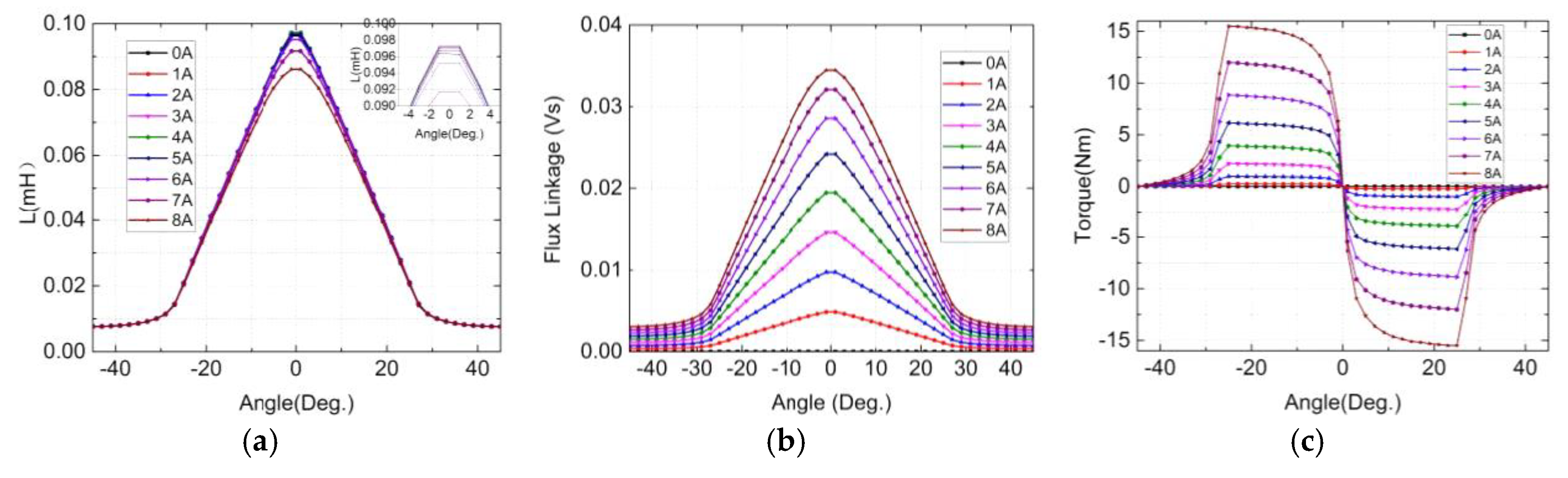
Figure 3.
Linear interpolation results: (a) 3-D relationships of Ψ-i-θ; (b) 3-D relationships of T-i-θ.
Figure 3.
Linear interpolation results: (a) 3-D relationships of Ψ-i-θ; (b) 3-D relationships of T-i-θ.
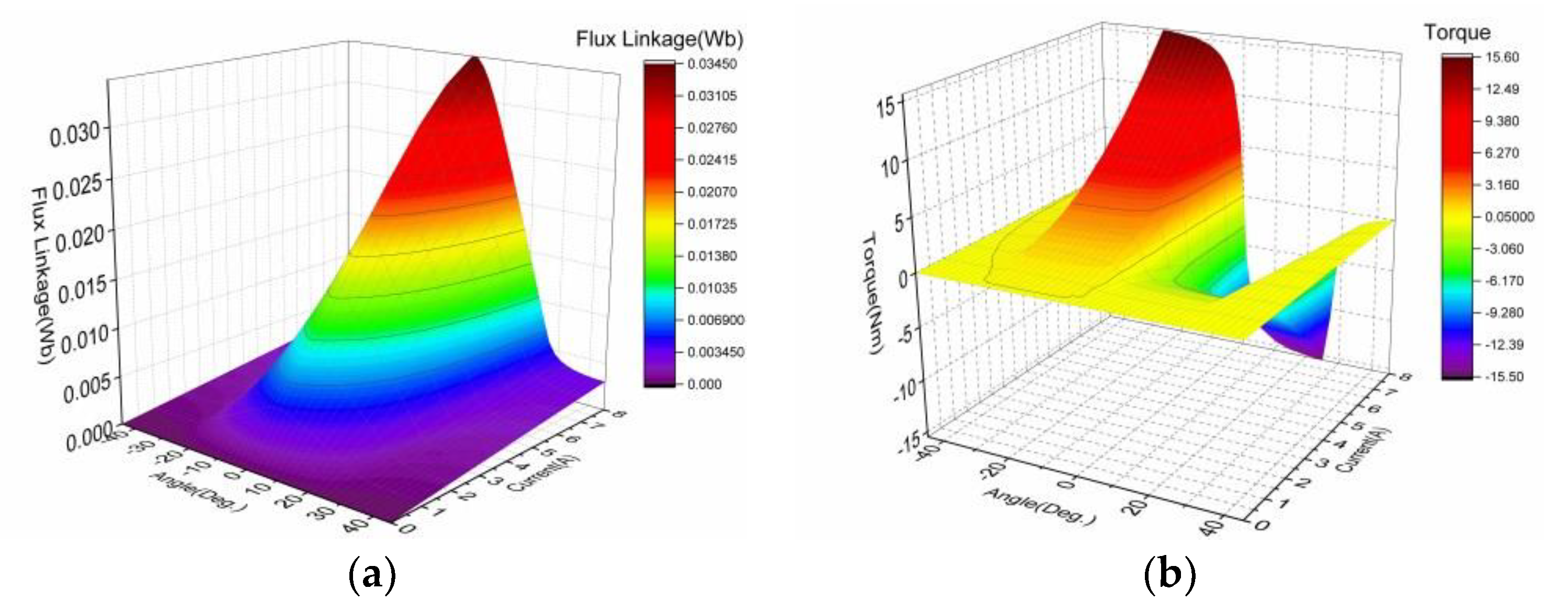
Figure 4.
Illustration of a torque sharing function (TSF).

Figure 5.
Typical profiles of four conventional TSFs. (a) Torque Reference; (b) Current Reference; (c) Flux Linkage; (d) Absolute Value of RCFL.
Figure 5.
Typical profiles of four conventional TSFs. (a) Torque Reference; (b) Current Reference; (c) Flux Linkage; (d) Absolute Value of RCFL.

Figure 6.
Comparison of four conventional TSFs: (a) absolute value of the rate-of-change of the flux linkage (RCFL); (b) peak phase current; (c) rms phase current.
Figure 6.
Comparison of four conventional TSFs: (a) absolute value of the rate-of-change of the flux linkage (RCFL); (b) peak phase current; (c) rms phase current.
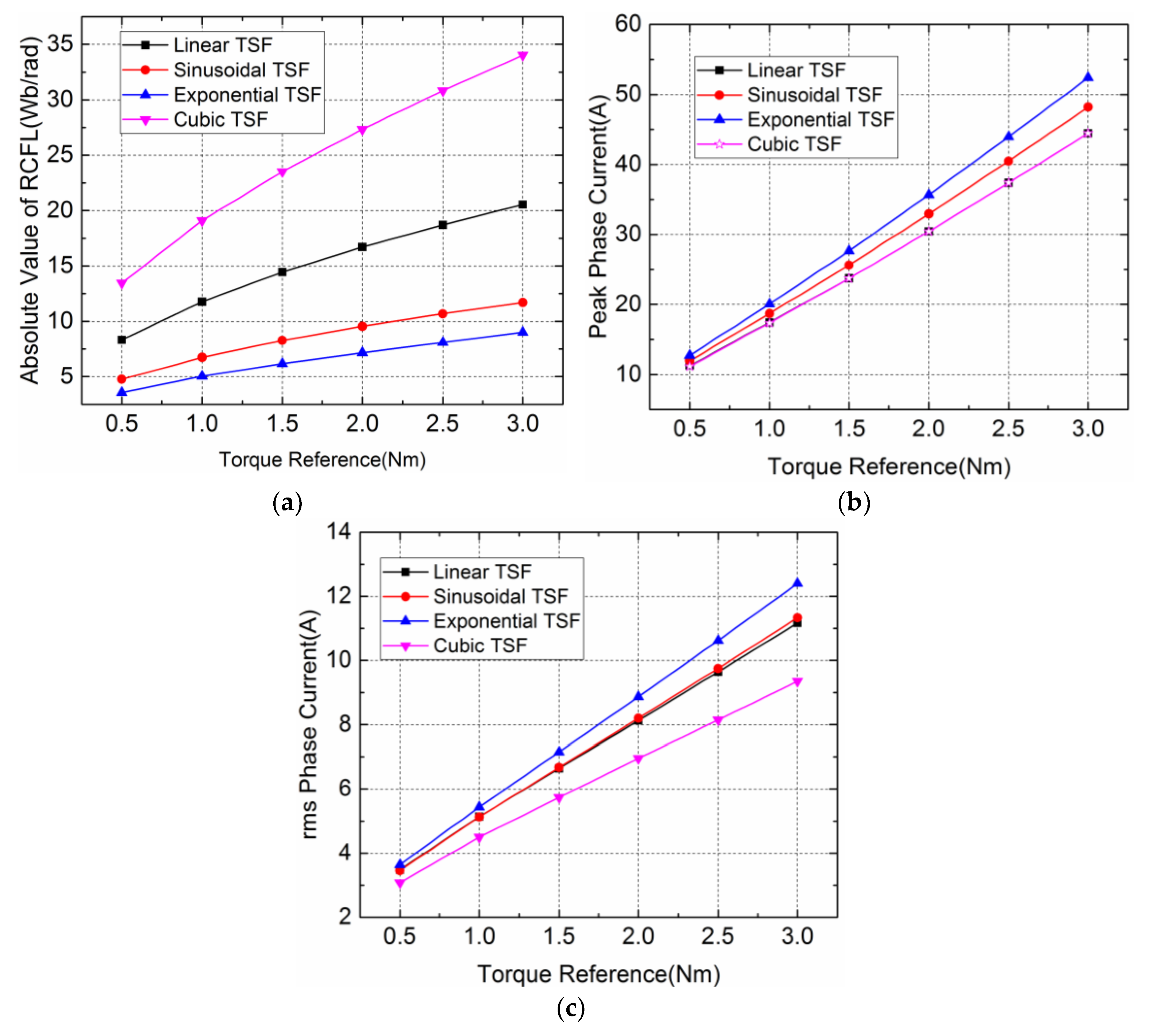
Figure 7.
Typical profiles of the proposed TSF family. (a) Torque Reference; (b) Current Reference; (c) Flux Linkage; (d) Absolute Value of RCFL.
Figure 7.
Typical profiles of the proposed TSF family. (a) Torque Reference; (b) Current Reference; (c) Flux Linkage; (d) Absolute Value of RCFL.

Figure 8.
Comparison of the proposed TSFs: (a) absolute value of the RCFL; (b) peak phase currents; (c) rms phase currents.
Figure 8.
Comparison of the proposed TSFs: (a) absolute value of the RCFL; (b) peak phase currents; (c) rms phase currents.
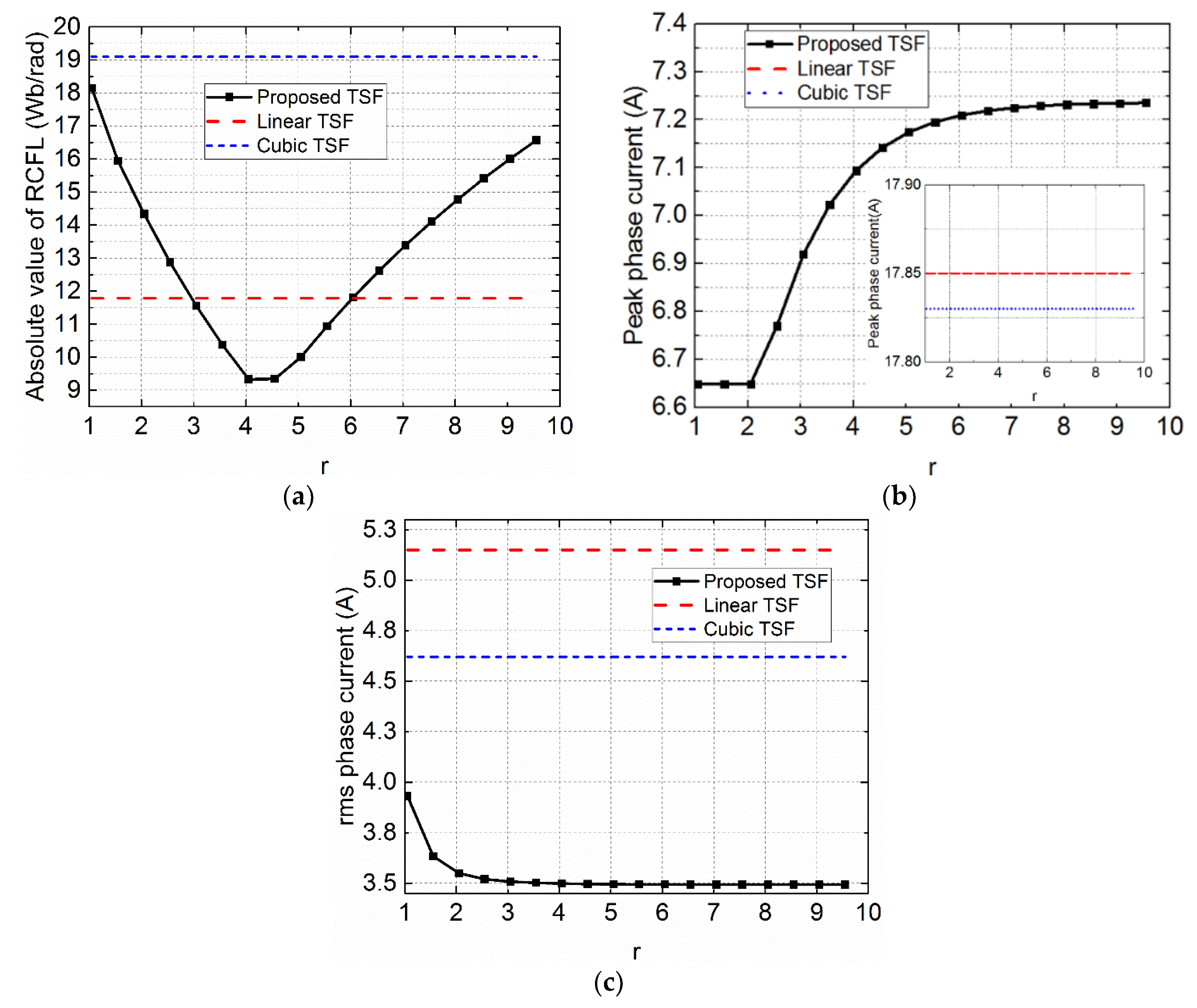
Figure 9.
Comparison of the calculated, FEM, and measured static torque characteristics for 0 to 8 A with an increment of 1 A.
Figure 9.
Comparison of the calculated, FEM, and measured static torque characteristics for 0 to 8 A with an increment of 1 A.

Figure 10.
Block diagram of the torque control using the TSF method.

Figure 11.
Simulation results (Tref = 1.5 Nm, 1000 rpm): (a) current chopping control (CCC); (b) Linear TSF; (c) Sinusoidal TSF; (d) TSF1 (r = 4).
Figure 11.
Simulation results (Tref = 1.5 Nm, 1000 rpm): (a) current chopping control (CCC); (b) Linear TSF; (c) Sinusoidal TSF; (d) TSF1 (r = 4).

Figure 12.
Simulation results (Tref = 1.5 Nm, 3000 rpm): (a) CCC; (b) Linear TSF; (c) Sinusoidal TSF; (d) TSF1 (r = 4).
Figure 12.
Simulation results (Tref = 1.5 Nm, 3000 rpm): (a) CCC; (b) Linear TSF; (c) Sinusoidal TSF; (d) TSF1 (r = 4).

Figure 13.
Comparison of CCC and different TSFs: (a) torque ripple; (b) rms phase current; (c) peak current.
Figure 13.
Comparison of CCC and different TSFs: (a) torque ripple; (b) rms phase current; (c) peak current.

Figure 14.
The values of the objective function J at different weight factors wf: (a) 1000 rpm; (b) 3000 rpm.
Figure 14.
The values of the objective function J at different weight factors wf: (a) 1000 rpm; (b) 3000 rpm.
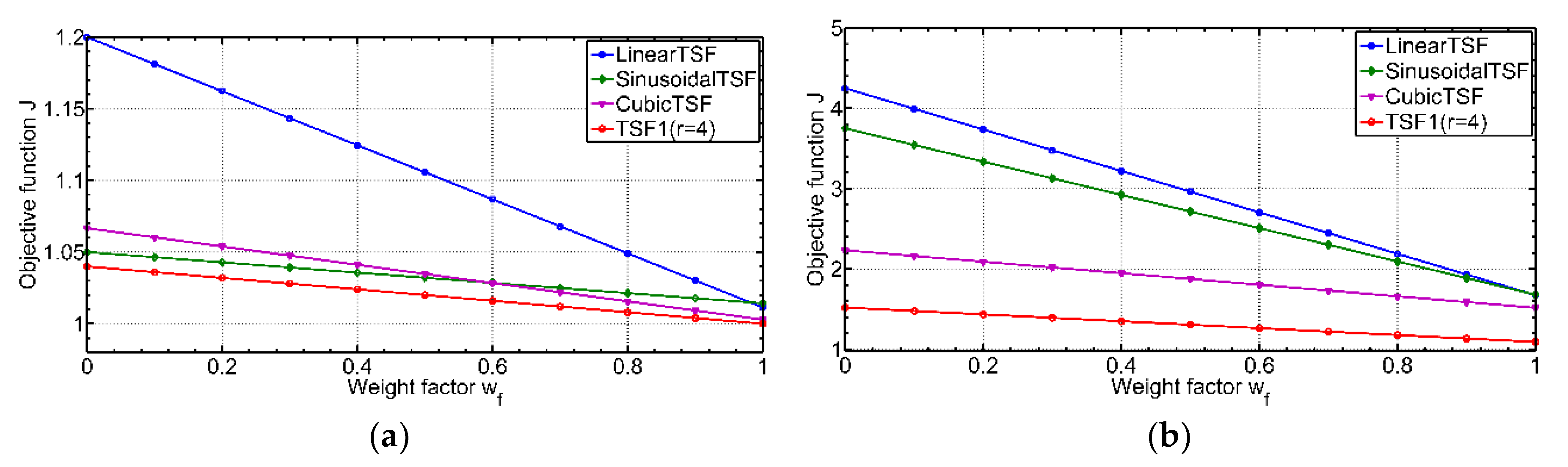
Figure 15.
Experimental setup of the SRM drive system.
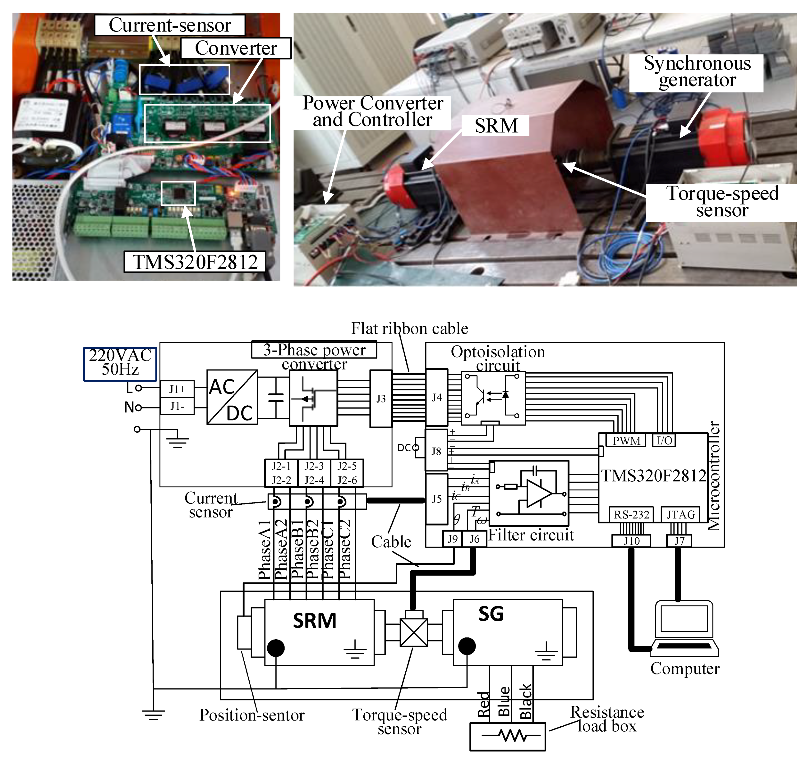
Figure 16.
Experimental results (speed = 3000 rpm, Tref = 1.5 Nm): (a) CCC; (b) Linear TSF; (c) Sinusoidal TSF; (d) TSF1 (r = 4).
Figure 16.
Experimental results (speed = 3000 rpm, Tref = 1.5 Nm): (a) CCC; (b) Linear TSF; (c) Sinusoidal TSF; (d) TSF1 (r = 4).

Figure 17.
Harmonic component and phase of the total torque (Tref = 1.5 Nm, speed = 3000 rpm): (a) CCC; (b) Linear TSF; (c) Sinusoidal TSF; (d) TSF1 (r = 4).
Figure 17.
Harmonic component and phase of the total torque (Tref = 1.5 Nm, speed = 3000 rpm): (a) CCC; (b) Linear TSF; (c) Sinusoidal TSF; (d) TSF1 (r = 4).

© 2018 by the authors. Licensee MDPI, Basel, Switzerland. This article is an open access article distributed under the terms and conditions of the Creative Commons Attribution (CC BY) license (http://creativecommons.org/licenses/by/4.0/).
Share and Cite
MDPI and ACS Style
Ye, W.; Ma, Q.; Zhang, P. Improvement of the Torque-Speed Performance and Drive Efficiency in an SRM Using an Optimal Torque Sharing Function. Appl. Sci. 2018, 8, 720. https://doi.org/10.3390/app8050720
AMA Style
Ye W, Ma Q, Zhang P. Improvement of the Torque-Speed Performance and Drive Efficiency in an SRM Using an Optimal Torque Sharing Function. Applied Sciences. 2018; 8(5):720. https://doi.org/10.3390/app8050720
Chicago/Turabian StyleYe, Wei, Qishuang Ma, and Poming Zhang. 2018. "Improvement of the Torque-Speed Performance and Drive Efficiency in an SRM Using an Optimal Torque Sharing Function" Applied Sciences 8, no. 5: 720. https://doi.org/10.3390/app8050720
Note that from the first issue of 2016, this journal uses article numbers instead of page numbers. See further details here.