Performance Evaluation of a Chinese Lean Iron Ore as the Oxygen Carrier in Multi and Short-Time Redox Cycles


Key Laboratory of Energy Thermal Conversion and Control of Ministry of Education, School of Energy and Environment, Southeast University, Nanjing 210096, China
*
Authors to whom correspondence should be addressed.
Appl. Sci. 2018, 8(5), 682; https://doi.org/10.3390/app8050682
Submission received: 9 March 2018
/
Revised: 21 April 2018
/
Accepted: 25 April 2018
/
Published: 27 April 2018
(This article belongs to the Special Issue Advances in Oxygen Carrier for Energy Applications)
Abstract
:The performance of a Chinese lean iron ore as the oxygen carrier in chemical looping combustion was investigated in a fixed bed reactor. Considering the short contact time between the fuel gas and oxygen carrier in the sub-pilot experimental setup, the short injection time of CO was employed in the reactor to simulate this event. The injection time of CO was set to 60 s, 50 s and 40 s respectively, to investigate its effects on the reactivity of the oxygen carrier. A total of 100 cyclic reactions under each condition were carried out to test the reactivity stability of the oxygen carrier. The oxygen carriers prior and after reactions were characterized using SEM, XRD and BET. Results showed that there was an activation process of the reactivity during initial cycles. The extension of the reaction time was beneficial to the diffusion of CO into the oxygen carrier and could improve the conversion of CO. Also, it could form larger pore volumes for gas diffusion in the oxygen carrier. However, it led to the formation of the Fe2SiO4 and severe sintering on the surface, which was harmful to the stability of the oxygen carrier’s reactivity.
1. Introduction
The production of pure CO2 was proposed by Lewis and Gilliland [1], which was similar to the process of chemical looping combustion. Richter and Knoche adopted this concept to improve the thermal efficiency of fossil fuel fired power plants [2]. Later, the chemical looping combustion (CLC) was firstly named and used for CO2 capture by Ishida et al. [3,4], and since then the concept of chemical looping has been used in many fields [5,6,7,8,9]. As an inherent CO2 separation technology without extra energy penalty, CLC has been considered as one of the most promising technologies to capture high-concentration CO2 [8,10]. In the CLC process, the oxygen carrier (OC) circulates between the air reactor and fuel reactor to transfer the oxygen from air to the fuel. Usually, the oxygen carrier is a kind of metallic oxide (MxOy). In the fuel reactor, the solid fuel is gasified herein with the gasification agent (e.g., H2O, CO2). The oxygen carrier reacts with the gasified gases or fuel gas to realize the non-flame combustion of the fuel (CnH2m), described as reaction Equation (1). Then, the reduced oxygen carrier particles (MxOy−1) are carried by the flue gas into the separator, where the oxygen carrier is separated. Subsequently, the reduced metallic oxide circulates into the air reactor and is reoxidized by the air, shown as Equation (2).
As a significant role in CLC, the oxygen carrier requires proper reactivity, mechanical and thermal performances. Currently, many successful operations have been conducted using synthetic OCs in pilot-scale gaseous fuel CLC systems. Synthetic OCs such as NiO, CoO, CuO, Mn3O4 and Fe2O3 presented favorable performances with high reactivity, high mechanical strength and low agglomeration [11,12,13,14,15,16]. To further enhance the reaction and/or mechanical performances, inert materials (e.g., Al2O3, SiO2, TiO2) were widely used as supports for the synthetic OCs [17,18,19,20,21,22]. However, it should be considered that the OC loss takes place continuously in the operation of pilot-scale CLC reactors, which is caused by the attrition along the flow channel [23,24]. The attrition and toxication of OCs are more severe in the solid fuel CLC process owing to the solid-solid contact between solid fuels and OC particles. Additionally, regular drain of fuel ash in CLC process is always accompanied by the OCs loss [25,26,27]. The synthetic OCs always need high-grade metal oxides and/or pure compounds, which increases the cost of raw materials. This would be a constraint factor of synthetic OCs for commercial applications.
In recent years, finding low-cost OCs with relatively high reactivity and strong mechanical strength has become a dominant research focus. Abundant ore resources are possible oxygen carriers, such as natural copper, manganese and iron minerals [28,29,30,31]. Due to their low cost, environmental friendliness and abundance, iron-based minerals (e.g., ilmenite, hematite, magnetite, limonite, etc.) have been some of the most attractive OCs and have been widely used [31,32]. Their uncontrollable compositions and structures made the natural iron-based ores exhibit variable reactivities and mechanical performances in the process of CLC. As for reaction mechanism study, studies in Chalmers University of Technology demonstrated that the ilmenite offered attractive performances in CLC with high conversion of fuel gas [33,34]. The ilmenite also has been investigated in University of Kentucky and it showed satisfying reactivity, mechanical strength and oxygen transport capacity [23,35]. A comprehensive comparison of the performances of different iron-based ores including hematite, ilmenite, limonite, magnetite and taconite was carried out by National Energy Technology Laboratory in US. Results illustrated the reactivities of ores were worse than that of pure Fe2O3 due to the less active compositions content. However, the magnetite and limonite demonstrated better performances than hematite, ilmenite and taconite [36]. In Universität Siegen, tests of two ilmenites in fixed bed reactor demonstrated they had high gas conversions, however the sintering of particles might be a substantial problem [37]. In China, the natural hematite and natural iron ore have been evaluated as oxygen carriers in CLC [27,38]. The previous studies demonstrated that natural ores had relatively satisfying performances. However, they were high-grade minerals which had a high cost of the raw materials. The real situation of the iron minerals is that the low-grade lean iron ore takes much more inventory than the high-grade ones, thus the lean iron ore has more advantage in the price. If the lean iron ore is demonstrated to be capable for commercial applications, the operation cost of CLC can be decreased. But, the lean iron ore contains many other components which may affect the reduction of active component and make the reaction mechanism more complex. There were few literatures focusing on the properties of the lean iron ore. Previously, our group has designed and built a high-flux circulated fluidized bed (CFB) unit for chemical looping combustion [39]. In this unit, the riser was applied as the fuel reactor. Another 50 kW CLC unit in Southeast University also adopted fast fluidized bed as fuel reactor [40]. In these units, the contact time between fuel and oxygen carrier was short. And the OCs usually cannot be totally reduced. Thus, the previous studies on the OC performances may deviate from the real circumstance of OCs in practical operations.
In this study, we conducted the experiment to investigate the performances of a type of Chinese lean iron ore as oxygen carrier. To be more practical, the effects of short-time and multicycle redox process on the performances of OC in CLC were investigated in this work. With the consideration of cost efficiency for future commercial application, a kind of Chinese lean iron ore was adopted as the oxygen carrier. The injection time of reduction gas was set to 60 s, 50 s and 40 s in a bench-scale fixed bed reactor to simulate the short residence times of oxygen carrier in reduction atmosphere in a dual circulated fluidized bed system. The effects of short reduction times on the reactivity were investigated. Multi-redox cycles were carried out to evaluate the stability of the reactivity. And the mechanisms of reactivity changes were analyzed by the characterizations of OCs using SEM, BET and XRD.
2. Experimental
2.1. Experimental Material
In this work, a kind of lean iron ore from Hebei Province in China was selected as the oxygen carrier. The performance study can offer the theoretical possibility for its future commercial application.
To prepare the oxygen carrier, the lean iron ore was crushed first. The obtained particles of the lean iron ore were calcined in muffle furnace at 1173 K for 2 h to be fully oxidized. After calcination, the particles were sieved to a size range of 0.35–0.83 mm. The sieved particles were irregular polyhedrons with sharp apparent edges and corners, as shown in the Figure 1. The apparent density of the particles is about 2930 kg/m3 while the bulk density is about 1600 kg/m3. The compositions of the prepared oxygen carrier, analyzed by X-ray fluorescence, are presented as Table 1.
2.2. Experimental Setup and Procedure
The experimental setup used in this work was a batch-scale fixed bed, as shown in Figure 2. The reactor was made of quartz tube with inner diameter of 40 mm, and a porous board was placed at the medium of the reactor. The temperature in the reactor was precisely controlled by a K-thermocouple and fuzzy PID controller. The gases used in the experiment were supplied by the gas cylinders produced at Nanjing Shangyuan gas plant (Nanjing, China). The flow rates of the gases were controlled by the S49 32/MT mass flow controllers produced by Beijing HORIBA METRON Instruments Co. Ltd. (Beijing, China).
Prior to each test, 50 g of the calcined lean iron ore was placed on the porous board and then the reactor was heated to 1223 K in N2 atmosphere. When the temperature was kept stable, the redox cycles were carried out. The reduction process was initiated by injecting the 11% CO (diluted with N2) into the reactor. During different tests, the gas flow rate of the CO kept 1 L/min with the injection times of 60 s, 50 s and 40 s. After the reduction period, the 99.99% N2 stream was introduced for purge period to avoid the effects of residual CO and CO2 on the reaction. The gas flow rate was set as 1 L/min. Then the pure air was switched to replace the N2 to oxidize the reduced oxygen carrier with the gas flow of 1 L/min as well. The oxidation of oxygen carrier lasted for 60 s to guarantee that the oxygen carrier was fully oxidized. After oxidation period, the N2 was injected into the reactor for the second purge process to initiate the next cycle. The production gas leaving the reactor was filtered and dried. After cooling, the compositions of the flue gas were analyzed by the gas analyzer produced by Messgeräte für Rauchgase und Umweltschutz GmbH (MRU) in Neckarsulm Germany, whose sampling interval was set as 1 s during the whole reaction process.
A single redox cycle included CO reduction (denoted as R), purge process using N2 (denoted as P1), air oxidation (denoted as O), and the second purge process (denoted as P2). In the experiment, the first purge process was adopted to sweep out the residual unreacted CO and the production CO2. The purpose of the second purge process was to sweep the residual air in the reactor and initial the next redox cycle. The CO injection time in test 1 was the longest in these three tests, which resulted in more carbonaceous gases in the reduction process. Thus the first purge time was also the longest as 180 s. The first purge process of test 2 and test 3 lasted for 120 s. The total time of test 3 was intended to be the same as that of test 2. The detailed experimental conditions are listed in Table 2. In order to investigate the reactivity stability of the oxygen carrier, 100 cycles were done in each test.
3. Reactivity of Oxygen Carrier with Different Reaction Times
3.1. Reactivity in a Single Cycle
With the reaction temperature at 1223 K, the injection time of CO was changed, and the reaction characteristics in a single cycle of the lean iron ore under three different conditions were tested. In order to fully activate the iron ore, the tenth cycle was chosen as the study object in this section. The gas concentrations in test 1 to test 3 are shown in Figure 3.
When the injection time of CO was 60 s, the maximum of CO2 concentration reached 7.4%. However, there was also residual CO which could not be converted. The peak concentration of unconverted CO was 3.0%. When the CO injection times were 50 s and 40 s respectively, the maximums of CO2 concentrations were 6.6% and 5.9% while the corresponding CO concentrations were 3.7% and 4.4%. During the oxidization period, once the pure air went into the reactor, the O2 in the air reacted with the reduced oxygen carriers quickly. When the oxygen carrier was fully oxidized, the O2 concentration climbed to 21%. It is clear in Figure 3 that the different injection times could cause the different reaction times for the reduction of oxygen carrier. As the injection time of CO was shortened, the CO concentration in the flue gas increased while the concentration of CO2 decreased. The maximum values of the concentrations might be related with the reaction rate during the whole reduction process. The reaction rate was the comprehensive results of the kinetics, gas concentrations, partial pressure and so on. However, generally the conversion rate exhibits an increasing trend in the initial stage of a reaction. When the injection time was 40 s, the average reaction rate was less than that of the test 1. From this perspective, the CO2 concentration in test 3 should be less than that of test 1 while the CO concentration in test 3 should be higher than that of test 1. These results matched well with the experimental data in Figure 3. Following, these results were used to analyze the effects of the CO injection time on the conversion of the CO.
To calculate the conversion of CO, the gas volume of carbonaceous gas need to be acquired. During the experiments, 11% CO was adopted as the reduction gas. The total gas flow rate was 1 L/min, and thus the flow rate of pure CO was 0.11 L/min. In the flue gas, the total volume of each carbonaceous gas can be calculated by the following equation:
where, Vi is the gas volume of i; i denotes CO or CO2; tt is the total reaction time; ci is the concentration of gas i and is the total flow of the flue gas.
The conversion of CO can be obtained by Equation (4).
In the test 1 to test 3, the volume integral results and conversion of CO are listed in Table 3.
Previously, our group has designed and built a high-flux CFB unit for chemical looping combustion [39], in which the amount of oxygen carrier was excess to the demand amount of fuel. To simulate the large ratio of the oxygen carrier to fuel, the injected CO was less than the demand amount of the total conversion for oxygen carrier in this work. With the increase of injection time of CO, the conversion of CO became larger. Also, Table 3 illustrated that the increasing interval of CO conversion between test 2 and test 3 was much larger than that between test 2 and test 1, which demonstrated that the conversion rate declined against time.
3.2. Investigation on Multi Cycles
Figure 4 illustrates the CO2 concentration variation with the number of cycles under different CO injection times of 60 s, 50 s and 40 s. In the multi-redox cycles, CO2 concentration kept in a relatively stable range, which demonstrated that the lean iron ore had satisfying reaction stability as the oxygen carrier. When the injection times of CO were 60 s, 50 s and 40 s, the CO2 concentrations were in the ranges of 6.7–7.5%, 6.4–6.7% and 5.9–6.1% separately. The time domain of each test was too long to exhibit the detailed variation in every single cycle. The maximum of the CO2 concentration in Figure 4 could be employed to analyze the reactivity changes of the oxygen carrier. Thus, the following analyses were based on the maximum values of the CO2 concentrations.
Compared with test 2 and test 3, the fluctuation interval of CO2 concentration in test 1 was the greatest. However, it was common in three tests that the CO2 concentration increased slightly in the initial several cycles, which demonstrated that the activity of the lean iron ore gradually increased and more CO was oxidized to CO2. It exhibited that there was an activation process of the lean iron ore. The activation period and its mechanism have been found and investigated in previous literatures [41,42,43,44]. This was attributed to the porosity increase of oxygen carrier particles in the initial cyclic reactions. As the cycle number increased, the CO2 concentration maintained in a steady range and then decreased gradually. The reason for this phenomena was that the oxygen transport capacity of the lean iron ore maintained at a relatively stable stage in the following cycles. With the increase of the cycles, the porous structure of the natural lean iron ore was destroyed, which led to the decrease of the activity and oxygen transport capacity of the oxygen carrier.
Incomplete reaction between the lean iron ore and CO was caused by reducing the exposure time of oxygen carrier in reducing atmosphere. In this case, the CO had not diffused into the inner core of oxygen carrier particles so that only the surface structure changed. Shortening the injection time of CO reduced the formation of FeO and/or Fe on the OC surface, which could avoid the secondary reaction between FeO/Fe and other compositions and could maintain the reactiveness of the lean iron ore. It should be noted that due to the breaks in a longtime redox, the total time exceeded the continuous operation time of 100 cycles. During the breaks, the reactor was in the N2 atmosphere.
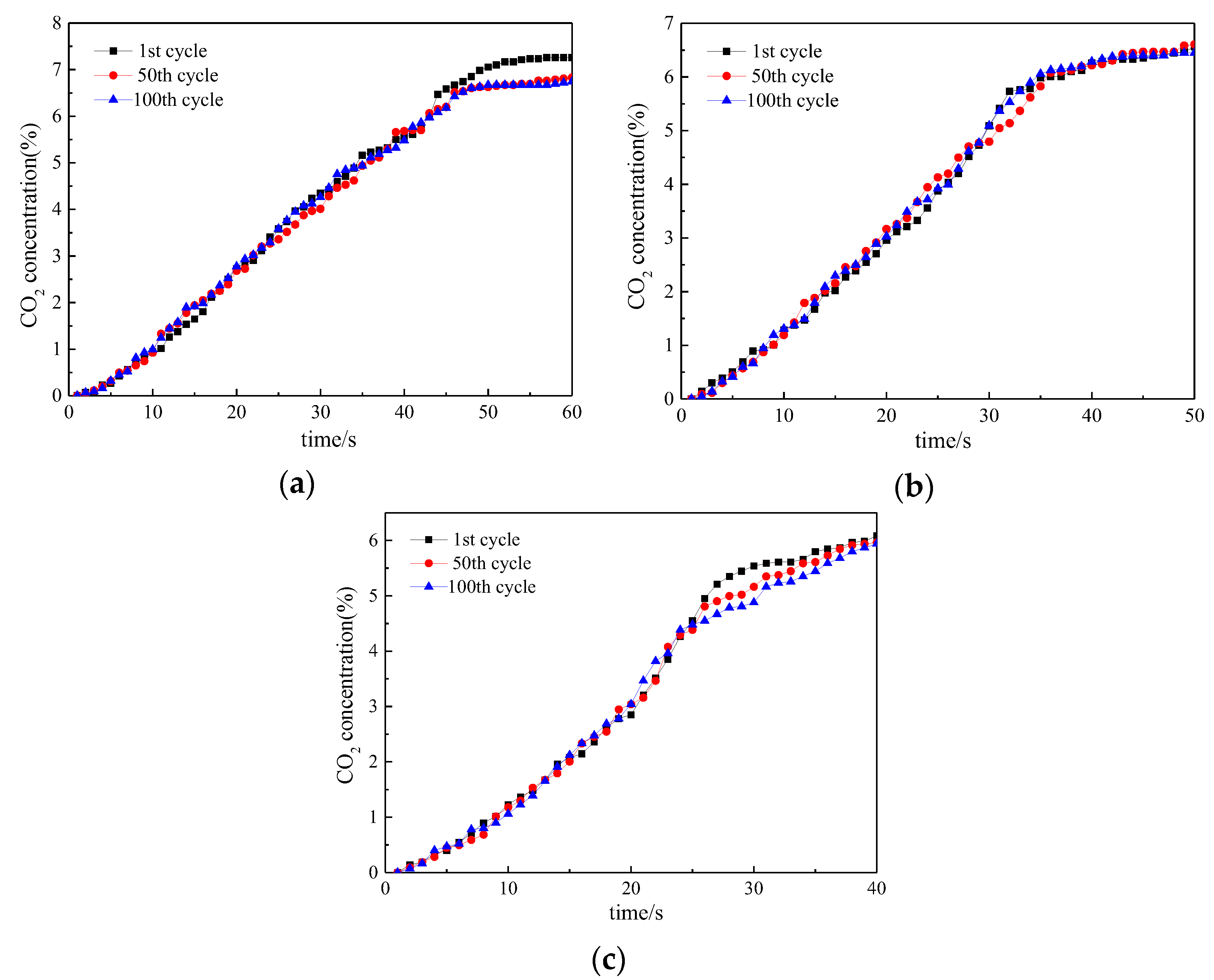
Figure 5 and Figure 6 illustrate the CO2 and CO concentrations in the reduction periods of the 1st, 50th, and 100th cycles separately. Results demonstrated that the concentration of CO increased gradually with the increase of the cycles while the concentration of CO2 decreased accordingly in the reduction stage of the cyclic reaction.
The CO2 concentration in test 1 decreased from 7.8% to 6.8% while it came down from 6.6% to 6.4% in test 2 and from 6.1% to 5.9% in test 3. The declines of CO2 concentration demonstrated the degradation of the reactivity after multi cycles.
In these tests, the CO curve could reflect the reaction rate and the conversion of the oxygen carrier. Concretely, once the CO got into the reactor, the CO diffused in the N2 atmosphere. When the CO diffused into the oxygen carrier particles, it reacted with the oxygen carrier producing the CO2. In the initial stage, the reaction rate was fast and it consumed the CO quickly. Later, the reaction rate slowed down resulting in the climbing of CO concentration. In a single test, the minimum of CO concentration appeared in the 1st cycle while the peak concentration was in the 100th cycle. The differences among the maximum values in the same test meant the reactivity destruction of the oxygen carrier. When the injection times of CO were taken as 60 s, 50 s and 40 s, the minimums were 3.1%, 3.7% and 4.3% while the maximums were 3.7%, 4.0% and 4.5% separately. It was obvious that reducing the injection time of CO could cause the increase of CO concentration and the decrease of the reduction extent of the oxygen carrier. Also, the difference between the CO concentration curves of the 1st cycle and the 100th cycle was getting smaller with the decrease of tCO. The phenomenon denoted that the reactivity of the oxygen carrier was more stable in short tCO.
The O2 concentrations during the oxidation process were shown in Figure 7.
During the oxidization period in these tests, the oxygen concentration decreased with the number of cycles due to the relatively low reactivity of lean iron ore after multi cycles. With the increase of cyclic number, the destruction of the reactivity could cause the lower conversion of the oxygen carrier in the reduction process. Thus, less O2 was needed in the oxidization period, and the O2 concentration reached 21% more quickly.
3.3. Lifetime Assessment of Oxygen Carrier
It has been demonstrated that the iron oxidation state of Fe2O3 is applicable for industrial chemical looping combustion transforming to Fe3O4, although it has different states (Fe2O3, Fe3O4, FeO and Fe) [45]. For the oxygen carrier, there was a conversion destruction during a longtime operation. The lifetime of oxygen carriers can be assessed by the following equation:
where, tlf is the lifetime of oxygen carrier in CLC; top is the total operation time; ΔXOC is the conversion destruction of oxygen carrier during longtime operation.
The conversion of oxygen carrier can be calculated by the CO2 produced in the redox cycles. Usually, the conversion of oxygen carrier XOC is defined as follow:
where, mox is the mass of oxygen carrier in totally oxidized state; m denotes the instantaneous mass of oxygen carrier particles; mred represents the mass of oxygen carrier when it is totally reduced. In these tests, the Fe2O3 in oxygen carriers was not totally converted to Fe3O4. Thus, the total reduced state of Fe2O3 was chosen as Fe3O4.
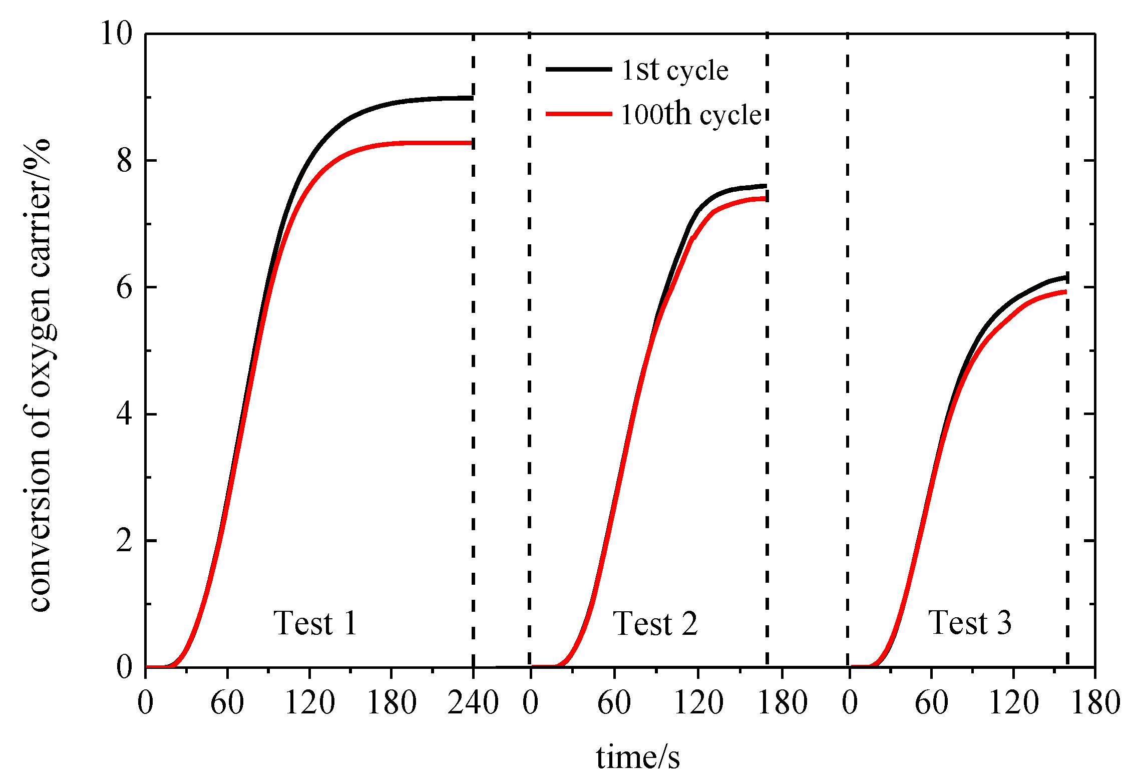
The conversions of the oxygen carrier in the 1st and 100th cycles under different conditions are shown in Figure 8.
The conversions of the oxygen carriers in the first cycles were 9.0%, 7.6% and 6.2% separately while they were 8.3%, 7.4% and 6.0% in the 100th cycles. The declines of the conversions were 0.7%, 0.2% and 0.2% separately in these tests. To assess the lifetime of oxygen carrier, the theoretical times of 100 cycles were adopted as operation times which were 800 min, 500 min and 500 min in the test 1 to test 3. The calculated lifetimes of oxygen carriers under the conditions of test 1 to test 3 were 1888 h, 4234 h and 4475 h separately, which demonstrated that the reduction time had a great effect on the oxygen carrier’s lifetime.
4. Analyses and Discussion
4.1. SEM Analysis
The calcined lean iron ore and the oxidized oxygen carriers after 100 cycles in test 1, test 2 and test 3 were characterized by SEM, shown as Figure 9 and Figure 10.
Figure 9a and Figure 10a demonstrated that the surface of fresh oxygen carrier was compactly covered with plate-like crystals. There were little voids on the fresh oxygen carrier, which offered little contact area for the gas-solid reaction. After tests, the plate-like structure and the compact surface were destructed to different extents. Figure 10b showed that after test 1, the surface of OC was still compact but the apparent edges and corners of the crystals disappeared. After test 2 and test 3, the surfaces of oxygen carriers were loose with more voids. For the OC after test 3, the plate-like structure could be observed clearly.
It is known that the voids are beneficial to the gas-solid contact. Results demonstrated that increasing the injection time of CO was harmful to the formation of voids on the surface. The oxidation of oxygen carrier could generate lots of heat. The long time reduction made more Fe2O3 convert to Fe3O4. Thus, in the corresponding oxidation period, more heat was generated which resulted in the local high temperature on the surface and sintering of the plate-like crystals. When the CO introducing time was shortened, the voids on the surface became much larger and the sintering greatly reduced. With the decrease of tCO, there was not much time for CO to diffuse into the inner of the particles and the reactions took place on the surface of the particles. Thus, less injection time of CO was beneficial to the reactivity stability of oxygen carriers.
4.2. XRD and BET Analyses
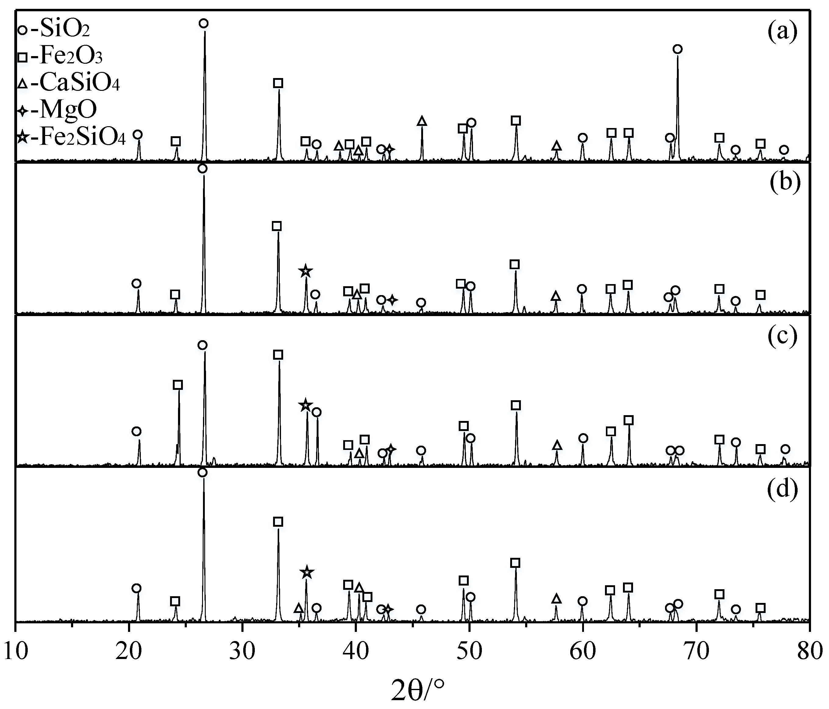
The XRD results of fresh oxygen carrier and oxygen carriers after the last oxidation process in test 1 to test 3 are shown as Figure 11.
Under different conditions, the XRD analyses of these oxygen carriers were similar, which meant that the injection time of CO could not change the internal phase and components. The Fe-containing composition was Fe2O3, except Fe2SiO4. The Fe2SiO4 could be found in the oxygen carriers after different tests. This was due to the reaction between Fe2O3 and SiO2 under the local high temperature condition over multi cycles. The property of the Fe2SiO4 was stable, which caused the decrease of Fe2O3 and the decline of the reactivity of oxygen carriers. This phenomenon also has been found in previous work [46,47]. Meanwhile, the melting point of Fe2SiO4 is relatively low [46], and the local high temperature from exothermic reaction could lead to the melting of Fe2SiO4 and the sintering of oxygen carriers.
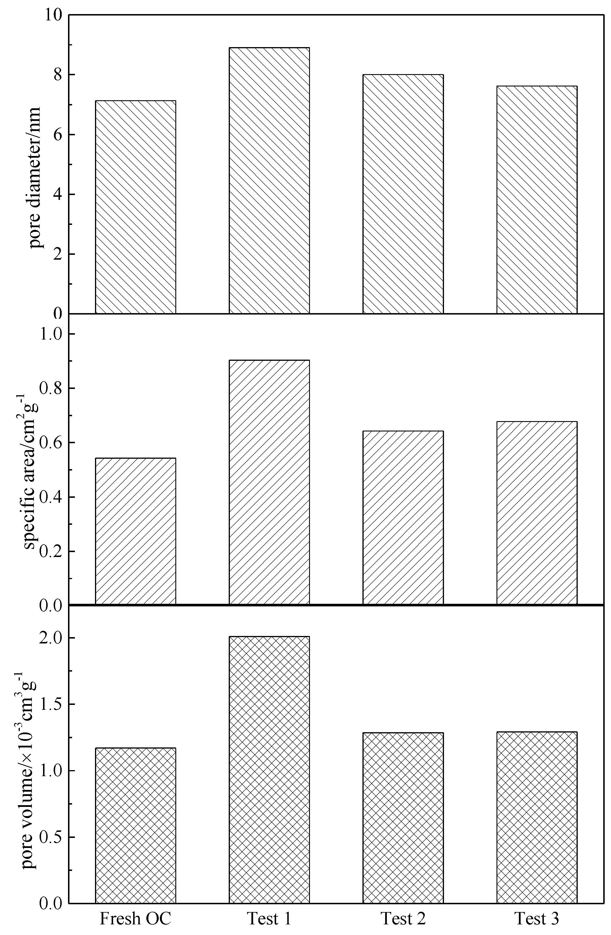
The BET results of these oxygen carriers are shown as Figure 12.
The pore diameter, volume and specific area of the oxygen carriers after 100 cycles were larger than those of the fresh oxygen carrier. These parameters increased with the injection time of CO. The specific areas and pore volumes of oxygen carriers after test 2 and test 3 were almost same. That might be the fact that the reaction did not diffuse into the inner of particles. The SEM results demonstrated that the surface of OC after test 1 was compact, however, the pore volume of OC after test 1 was the biggest. It demonstrated that the compact surface was caused by the sintering, and the inner porous structure still maintained. Large cycle number was beneficial to form the porous structure in the oxygen carrier and increase the specific surface area, which could promote the reaction between the oxygen carrier and CO.
5. Conclusions
The reactivity of the lean iron ore as oxygen carrier was investigated under different CO injection times of 60 s, 50 s and 40 s in a bench-scale fixed bed reactor. 100 cycles were done in each test to evaluate the reaction stability of the OC. SEM, XRD and BET were used to analyze the characterizations of the oxygen carriers. From the results, the following conclusions could be drawn.
(1) The degree of the reduction was positively correlated with the injection time of CO while the oxidization of oxygen carrier could be realized in a short time under different conditions.
(2) The cyclic stability and reactivity of the lean iron ore as oxygen carrier became stronger with the decrease of injection time of CO in multi cycles.
(3) There were severe sintering on the surface of the oxygen carrier when the tCO is becoming longer after multi cycles. And the formation of Fe2SiO4 in multi cycles could result in the decline of the reactivity of the oxygen carrier.
Author Contributions
Xu.W. and Xi.W. conceived and designed the experiments; X.H. and Z.J. performed the experiments; Y.S. and Xu.W. analyzed the data; B.J. supervised the research; Xu.W. wrote the paper.
Acknowledgments
This work has been financially supported by the National Natural Science Foundation of China (Nos. 51741603 and 51676038), Natural Science Foundation of Jiangsu Province (BK20170669), Fundamental Research Funds for the Central Universities (No. 3203007210), and Guangdong Provincial Key Laboratory of New and Renewable Energy Research and Development (No. Y707s41001).
Conflicts of Interest
The authors declare no conflict of interest.
References
- Lewis, W.K.; Gilliland, E.R. Productions of Pure Carbon Dioxide. U.S. Patent No. 2,665,972, 12 January 1954. [Google Scholar]
- Richter, H.J.; Knoche, K.F. Reversibility of Combustion Processes; ACS Publications: Washington, DC, USA, 1983. [Google Scholar]
- Ishida, M.; Zheng, D.; Akehata, T. Evaluation of a chemical-looping-combustion power-generation system by graphic exergy analysis. Energy 1987, 12, 147–154. [Google Scholar] [CrossRef]
- Ishida, M.; Jin, H. A new advanced power-generation system using chemical-looping combustion. Energy 1994, 19, 415–422. [Google Scholar] [CrossRef]
- Huang, Z.; Xu, G.; Deng, Z.; Zhao, K.; He, F.; Chen, D.; Wei, G.; Zhang, A.; Zhao, Z.; Li, H. Investigation on gasification performance of sewage sludge using chemical looping gasification with iron ore oxygen carrier. Int. J. Hydrogen Energy 2017, 42, 25474–25491. [Google Scholar] [CrossRef]
- Riley, J.; Siriwardane, R.; Tian, H.; Benincosa, W.; Poston, J. Kinetic analysis of the interactions between calcium ferrite and coal char for chemical looping gasification applications: Identifying reduction routes and modes of oxygen transfer. Appl. Energy 2017, 201, 94–110. [Google Scholar] [CrossRef]
- Shi, B.; Wu, E.; Wu, W. Novel design of chemical looping air separation process for generating electricity and oxygen. Energy 2017, 134, 449–457. [Google Scholar] [CrossRef]
- Nandy, A.; Loha, C.; Gu, S.; Sarkar, P.; Karmakar, M.K.; Chatterjee, P.K. Present status and overview of Chemical Looping Combustion technology. Renew. Sustain. Energy Rev. 2016, 59, 597–619. [Google Scholar] [CrossRef]
- Wang, K.; Yu, Q.; Qin, Q. The thermodynamic method for selecting oxygen carriers used for chemical looping air separation. J. Therm. Anal. Calorim. 2013, 112, 747–753. [Google Scholar] [CrossRef]
- Gauthier, T.; Yazdanpanah, M.; Forret, A.; Amblard, B.; Lambert, A.; Bertholin, S. CLC, a promising concept with challenging development issues. Powder Technol. 2017, 316, 3–17. [Google Scholar] [CrossRef]
- Kwak, B.S.; Park, N.; Ryu, S.O.; Baek, J.; Ryu, H.; Kang, M. Improved reversible redox cycles on MTiOx (M = Fe, Co, Ni, and Cu) particles afforded by rapid and stable oxygen carrier capacity for use in chemical looping combustion of methane. Chem. Eng. J. 2017, 309, 617–627. [Google Scholar] [CrossRef]
- Kwak, B.S.; Park, N.; Baek, J.; Ryu, H.; Kang, M. Improvement of reduction and oxidation performance of MMgOx (M = Fe, Co, Ni, and Cu) particles for chemical looping combustion. Powder Technol. 2017, 312, 237–247. [Google Scholar] [CrossRef]
- Rydén, M.; Hanning, M.; Corcoran, A.; Lind, F. Oxygen Carrier Aided Combustion (OCAC) of wood chips in a semi-commercial circulating fluidized bed boiler using manganese ore as bed material. Appl. Sci. 2016, 6, 347. [Google Scholar] [CrossRef]
- Frick, V.; Rydén, M.; Leion, H. Investigation of Cu–Fe and Mn–Ni oxides as oxygen carriers for chemical-looping combustion. Fuel Process. Technol. 2016, 150, 30–40. [Google Scholar] [CrossRef]
- Azimi, G.; Leion, H.; Mattisson, T.; Rydén, M.; Snijkers, F.; Lyngfelt, A. Mn–Fe Oxides with Support of MgAl2O4, CeO2, ZrO2 and Y2O3–ZrO2 for Chemical-Looping Combustion and Chemical-Looping with Oxygen Uncoupling. Ind. Eng. Chem. Res. 2014, 53, 10358–10365. [Google Scholar] [CrossRef]
- Rydén, M.; Lyngfelt, A.; Mattisson, T. CaMn0.875Ti0.125O3 as oxygen carrier for chemical-looping combustion with oxygen uncoupling (CLOU)—Experiments in a continuously operating fluidized-bed reactor system. Int. J. Greenh. Gas Control 2011, 5, 56–66. [Google Scholar] [CrossRef]
- Zhang, Y.; Doroodchi, E.; Moghtaderi, B. Comprehensive Study of Fe2O3/Al2O3 Reduction with Ultralow Concentration Methane under Conditions Pertinent to Chemical Looping Combustion. Energy Fuel 2015, 29, 1951–1960. [Google Scholar] [CrossRef]
- Wang, B.; Yan, R.; Lee, D.H.; Zheng, Y.; Zhao, H.; Zheng, C. Characterization and evaluation of Fe2O3/Al2O3 oxygen carrier prepared by sol–gel combustion synthesis. J. Anal. Appl. Pyrol. 2011, 91, 105–113. [Google Scholar] [CrossRef]
- Xu, Z.; Zhao, H.; Wei, Y.; Zheng, C. Self-assembly template combustion synthesis of a core–shell CuO@TiO2–Al2O3 hierarchical structure as an oxygen carrier for the chemical-looping processes. Combust. Flame 2015, 162, 3030–3045. [Google Scholar] [CrossRef]
- Zhang, Y.; Doroodchi, E.; Moghtaderi, B.; Han, X.; Liu, Y. Hydrogen Production from Ventilation Air Methane in a Dual-Loop Chemical Looping Process. Energy Fuel 2016, 30, 4372–4380. [Google Scholar] [CrossRef]
- Song, H.; Doroodchi, E.; Moghtaderi, B. Redox Characteristics of Fe–Ni/SiO2 Bimetallic Oxygen Carriers in CO under Conditions Pertinent to Chemical Looping Combustion. Energy Fuel 2012, 26, 75–84. [Google Scholar] [CrossRef]
- Adánez-Rubio, I.; Arjmand, M.; Leion, H.; Gayán, P.; Abad, A.; Mattisson, T.; Lyngfelt, A. Investigation of Combined Supports for Cu-Based Oxygen Carriers for Chemical-Looping with Oxygen Uncoupling (CLOU). Energy Fuel 2013, 27, 3918–3927. [Google Scholar] [CrossRef]
- Liu, F.; Zhang, Y.; Chen, L.; Qian, D.; Neathery, J.K.; Kozo, S.; Liu, K. Investigation of a Canadian Ilmenite as an Oxygen Carrier for Chemical Looping Combustion. Energy Fuel 2013, 27, 5987–5995. [Google Scholar] [CrossRef]
- Knutsson, P.; Linderholm, C. Characterization of ilmenite used as oxygen carrier in a 100 kW chemical-looping combustor for solid fuels. Appl. Energy 2015, 157, 368–373. [Google Scholar] [CrossRef]
- Demirel, Y.; Matzen, M.; Winters, C.; Gao, X. Capturing and using CO2 as feedstock with chemical looping and hydrothermal technologies. Int. J. Energy Res. 2015, 39, 1011–1047. [Google Scholar] [CrossRef]
- Mendiara, T.; de Diego, L.F.; García-Labiano, F.; Gayán, P.; Abad, A.; Adánez, J. On the use of a highly reactive iron ore in Chemical Looping Combustion of different coals. Fuel 2014, 126, 239–249. [Google Scholar] [CrossRef]
- Wang, X.; Liu, H.; Jin, B.; Zhao, J.; Sun, C.; Snape, C.E. Experimental Evaluation of a Chinese Sulfur-Containing Lean Iron Ore as the Oxygen Carrier for Chemical-Looping Combustion. Ind. Eng. Chem. Res. 2016, 55, 428–435. [Google Scholar] [CrossRef]
- Sundqvist, S.; Arjmand, M.; Mattisson, T.; Rydén, M.; ALyngfelt, A. Screening of different manganese ores for chemical-looping combustion (CLC) and chemical-looping with oxygen uncoupling (CLOU). Int. J. Greenh. Gas Control 2015, 43, 179–188. [Google Scholar] [CrossRef]
- Arjmand, M.; Leion, H.; Mattisson, T.; Lyngfelt, A. Investigation of different manganese ores as oxygen carriers in chemical-looping combustion (CLC) for solid fuels. Appl. Energy 2014, 113, 1883–1894. [Google Scholar] [CrossRef]
- Wang, K.; Tian, X.; Zhao, H. Sulfur behavior in chemical-looping combustion using a copper ore oxygen carrier. Appl. Energy 2016, 166, 84–95. [Google Scholar] [CrossRef]
- Matzen, M.; Pinkerton, J.; Wang, X.; Demirel, Y. Use of natural ores as oxygen carriers in chemical looping combustion: A review. Int. J. Greenh. Gas Control 2017, 65, 1–14. [Google Scholar] [CrossRef]
- Wang, J.; Zhao, H. Application of CaO-Decorated Iron Ore for Inhibiting Chlorobenzene during in Situ Gasification Chemical Looping Combustion of Plastic Waste. Energy Fuel 2016, 30, 5999–6008. [Google Scholar] [CrossRef]
- Leion, H.; Lyngfelt, A.; Johansson, M.; Jerndal, E.; Mattisson, T. The use of ilmenite as an oxygen carrier in chemical-looping combustion. Chem. Eng. Res. Des. 2008, 86, 1017–1026. [Google Scholar] [CrossRef]
- Leion, H.; Mattisson, T.; Lyngfelt, A. Use of ores and industrial products as oxygen carriers in chemical-looping combustion. Energy Fuel 2009, 23, 2307–2315. [Google Scholar] [CrossRef]
- Chen, L.; Bao, J.; Kong, L.; Combs, M.; Nikolic, H.S.; Fan, Z.; Liu, K. Activation of ilmenite as an oxygen carrier for solid-fueled chemical looping combustion. Appl. Energy 2017, 197, 40–51. [Google Scholar] [CrossRef]
- Tian, H.; Siriwardane, R.; Simonyi, T.; Poston, J. Natural Ores as Oxygen Carriers in Chemical Looping Combustion. Energy Fuel 2013, 27, 4108–4118. [Google Scholar] [CrossRef]
- Schwebel, G.L.; Filippou, D.; Hudon, G.; Tworkowski, M.; Gipperich, A.; Krumm, W. Experimental comparison of two different ilmenites in fluidized bed and fixed bed chemical-looping combustion. Appl. Energy 2014, 113, 1902–1908. [Google Scholar] [CrossRef]
- Jiang, S.; Shen, L.; Niu, X.; Ge, H.; Gu, H. Chemical Looping Co-combustion of Sewage Sludge and Zhundong Coal with Natural Hematite as the Oxygen Carrier. Energy Fuel 2016, 30, 1720–1729. [Google Scholar] [CrossRef]
- Wang, X.; Jin, B.; Zhu, X.; Liu, H. Experimental Evaluation of a Novel 20 kWth in Situ Gasification Chemical Looping Combustion Unit with an Iron Ore as the Oxygen Carrier. Ind. Eng. Chem. Res. 2016, 55, 11775–11784. [Google Scholar] [CrossRef]
- Xiao, R.; Chen, L.; Saha, C.; Zhang, S.; Bhattacharya, S. Pressurized chemical-looping combustion of coal using an iron ore as oxygen carrier in a pilot-scale unit. Int. J. Greenh. Gas Control 2012, 10, 363–373. [Google Scholar] [CrossRef]
- Adanez, J.; Cuadrat, A.; Abad, A.; Gayan, P.; de Diego, L.F.; Garcia-Labiano, F. Ilmenite Activation during Consecutive Redox Cycles in Chemical-Looping Combustion. Energy Fuel 2010, 24, 1402–1413. [Google Scholar] [CrossRef]
- Schwebel, G.L.; Leion, H.; Krumm, W. Comparison of natural ilmenites as oxygen carriers in chemical-looping combustion and influence of water gas shift reaction on gas composition. Chem. Eng. Res. Des. 2012, 90, 1351–1360. [Google Scholar] [CrossRef]
- Gu, H.; Shen, L.; Xiao, J.; Zhang, S.; Song, T. Chemical Looping Combustion of Biomass/Coal with Natural Iron Ore as Oxygen Carrier in a Continuous Reactor. Energy Fuel 2011, 25, 446–455. [Google Scholar] [CrossRef]
- Bao, J.; Li, Z.; Sun, H.; Cai, N. Experiment and rate equation modeling of Fe oxidation kinetics in chemical looping combustion. Combust. Flame 2013, 160, 808–817. [Google Scholar] [CrossRef]
- Mendiara, T.; Abad, A.; de Diego, L.F.; García-Labiano, F.; Gayán, P.; Adánez, J. Use of an Fe-Based Residue from Alumina Production as an Oxygen Carrier in Chemical-Looping Combustion. Energy Fuel 2012, 26, 1420–1431. [Google Scholar] [CrossRef]
- Bao, J.; Li, Z.; Cai, N. Interaction between iron-based oxygen carrier and four coal ashes during chemical looping combustion. Appl. Energy 2014, 115, 549–558. [Google Scholar] [CrossRef]
- Wang, B.; Zhao, H.; Zheng, Y.; Liu, Z.; Zheng, C. Chemical Looping Combustion of Petroleum Coke with CuFe2O4 as Oxygen Carrier. Chem. Eng. J. 2013, 36, 1488–1495. [Google Scholar]
Figure 1.
Photo of the crushed oxygen carrier particles.

Figure 2.
Bench-scale fixed bed reactor setup.
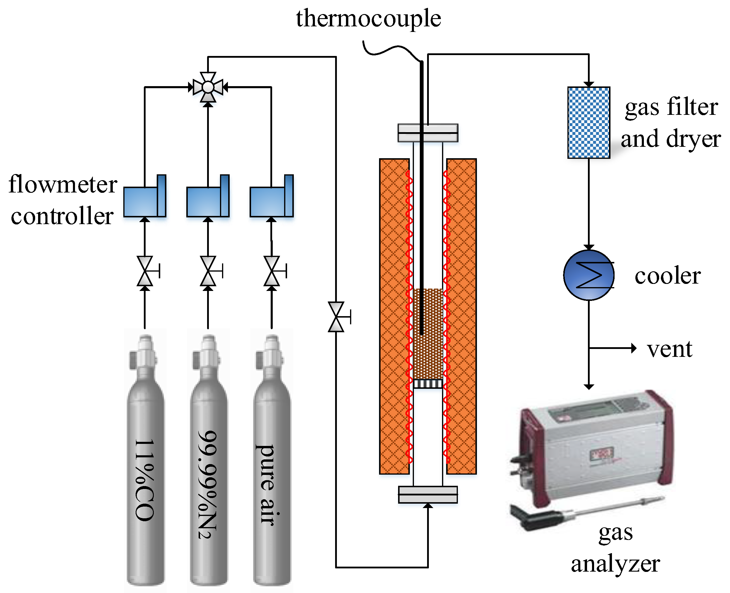
Figure 3.
The gas concentrations at the outlet under different conditions: (a) Test 1; (b) Test 2; (c) Test 3.
Figure 3.
The gas concentrations at the outlet under different conditions: (a) Test 1; (b) Test 2; (c) Test 3.
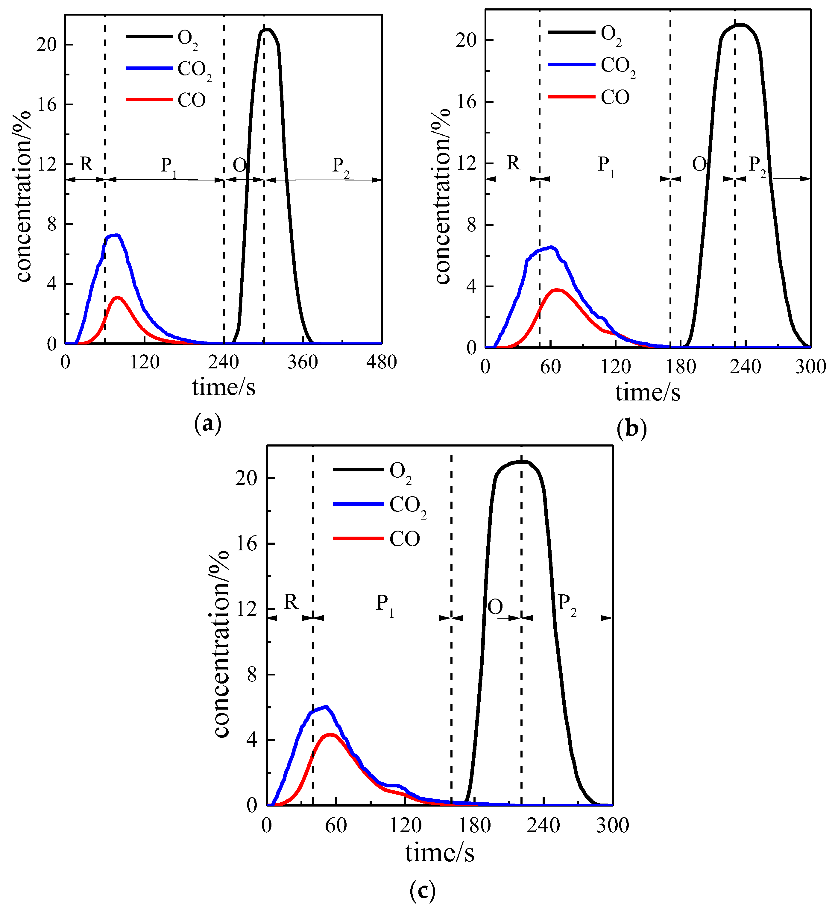
Figure 4.
CO2 concentration in the outlet gas in 100 cycles: (a) Test 1; (b) Test 2; (c) Test 3.
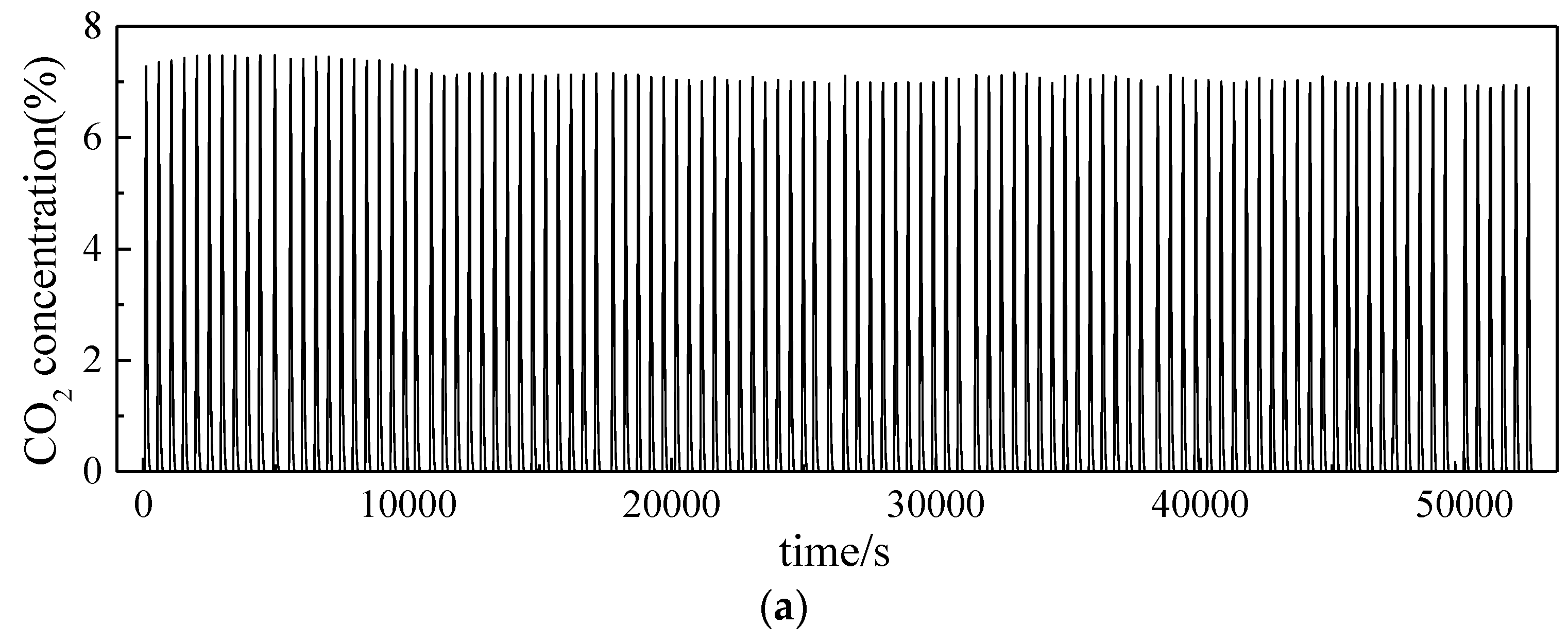
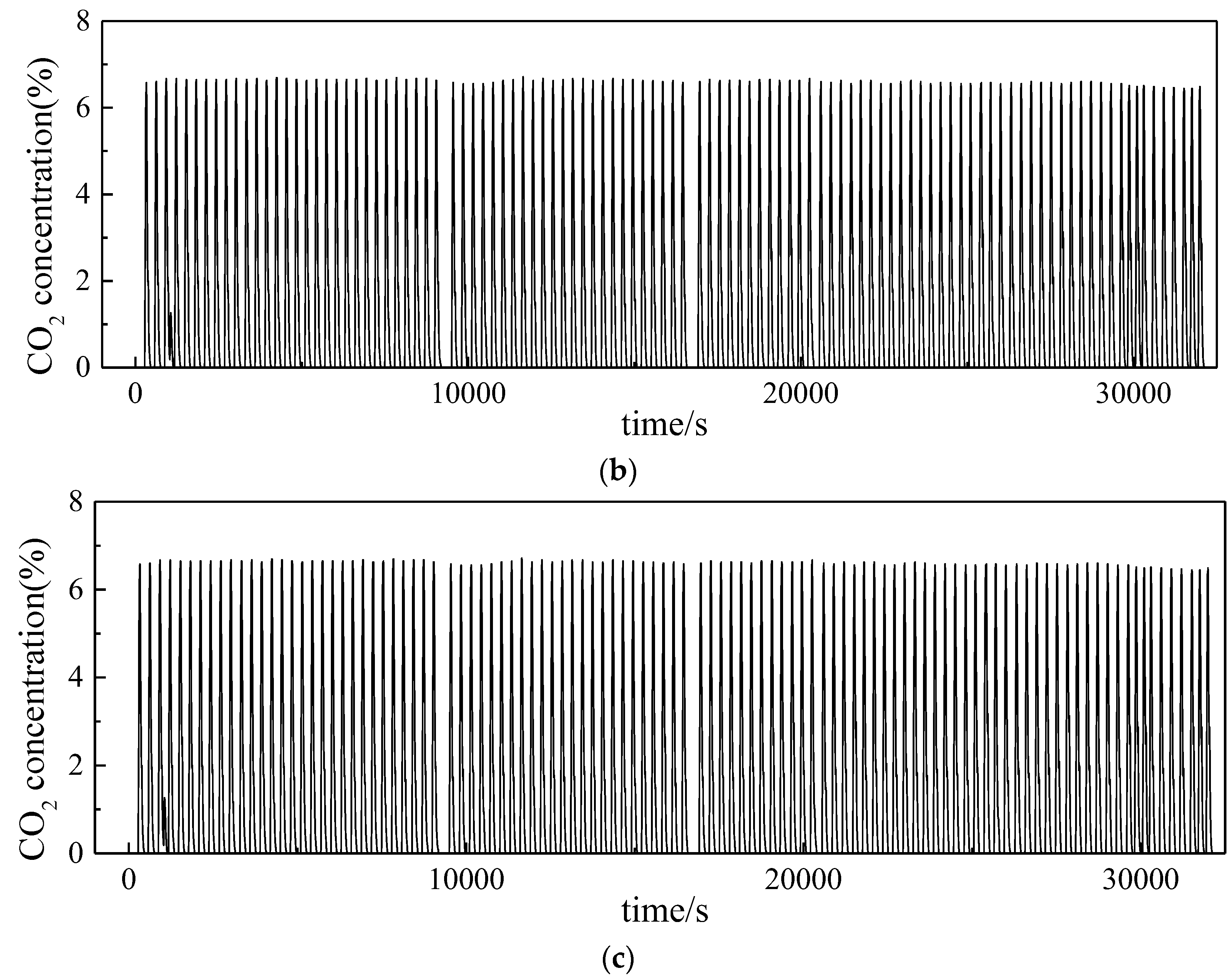
Figure 5.
The CO2 concentration in the reduction period: (a) Test 1; (b) Test 2; (c) Test 3.

Figure 6.
The CO concentration in the reduction period: (a) Test 1; (b) Test 2; (c) Test 3.
Figure 7.
The O2 concentration in the oxidization period: (a) Test 1; (b) Test 2; (c) Test 3.
Figure 8.
Conversions of oxygen carriers in the 1st and 100th cycles.

Figure 9.
SEM of whole oxygen carrier particle.

Figure 10.
SEM of surface micro-structure of oxygen carriers.
Figure 11.
XRD analyses of different oxygen carriers: (a) fresh oxygen carrier; (b) test 1; (c) test 2; (d) test 3.
Figure 11.
XRD analyses of different oxygen carriers: (a) fresh oxygen carrier; (b) test 1; (c) test 2; (d) test 3.

Figure 12.
BET results of different oxygen carriers.


Table 1.
The X-ray fluorescence (XRF) analysis results of lean iron ore oxygen carrier (OC).
| Component | Fe2O3 | SiO2 | Al2O3 | CaO | MgO | SO3 | Others |
|---|---|---|---|---|---|---|---|
| Mass Fraction/% | 44.16 | 18.93 | 2.98 | 17.09 | 7.43 | 2.35 | 7.06 |
Table 2.
Different experimental conditions.
| Test Number | Test 1 | Test 2 | Test 3 |
|---|---|---|---|
| Reducing gas | 11% CO | 11% CO | 11% CO |
| Oxidization gas | Pure air | Pure air | Pure air |
| Sweep gas | 99.99% N2 | 99.99% N2 | 99.99% N2 |
| Reduction temperature (K) | 1223 | 1223 | 1223 |
| Oxidization temperature (K) | 1223 | 1223 | 1223 |
| Gas flow (L/min) | 1 | 1 | 1 |
| CO injection time (s) | 60 | 50 | 40 |
| The first purge time (s) | 180 | 120 | 120 |
| Air injection time (s) | 60 | 60 | 60 |
| The second purge time (s) | 180 | 70 | 80 |
| Time of a single cycle (s) | 480 | 300 | 300 |
Table 3.
The conversion calculation of CO.
| Test | /L | /L | Conversion of CO |
|---|---|---|---|
| 1 | 0.021 | 0.089 | 80.9% |
| 2 | 0.025 | 0.067 | 73.9% |
| 3 | 0.028 | 0.045 | 61.6% |
© 2018 by the authors. Licensee MDPI, Basel, Switzerland. This article is an open access article distributed under the terms and conditions of the Creative Commons Attribution (CC BY) license (http://creativecommons.org/licenses/by/4.0/).
Share and Cite
MDPI and ACS Style
Wang, X.; Wang, X.; Hu, X.; Shao, Y.; Jin, Z.; Jin, B. Performance Evaluation of a Chinese Lean Iron Ore as the Oxygen Carrier in Multi and Short-Time Redox Cycles. Appl. Sci. 2018, 8, 682. https://doi.org/10.3390/app8050682
AMA Style
Wang X, Wang X, Hu X, Shao Y, Jin Z, Jin B. Performance Evaluation of a Chinese Lean Iron Ore as the Oxygen Carrier in Multi and Short-Time Redox Cycles. Applied Sciences. 2018; 8(5):682. https://doi.org/10.3390/app8050682
Chicago/Turabian StyleWang, Xudong, Xiaojia Wang, Xiaoyu Hu, Yali Shao, Zhaoyang Jin, and Baosheng Jin. 2018. "Performance Evaluation of a Chinese Lean Iron Ore as the Oxygen Carrier in Multi and Short-Time Redox Cycles" Applied Sciences 8, no. 5: 682. https://doi.org/10.3390/app8050682
Note that from the first issue of 2016, this journal uses article numbers instead of page numbers. See further details here.