Metasurface-Based Polarimeters

SDU Nano Optics, University of Southern Denmark, Campusvej 55, DK-5230 Odense, Denmark
*
Authors to whom correspondence should be addressed.
Appl. Sci. 2018, 8(4), 594; https://doi.org/10.3390/app8040594
Submission received: 1 March 2018
/
Revised: 30 March 2018
/
Accepted: 4 April 2018
/
Published: 10 April 2018
(This article belongs to the Special Issue Metasurfaces: Physics and Applications)
Abstract
:The state of polarization (SOP) is an inherent property of light that can be used to gain crucial information about the composition and structure of materials interrogated with light. However, the SOP is difficult to experimentally determine since it involves phase information between orthogonal polarization states, and is uncorrelated with the light intensity and frequency, which can be easily determined with photodetectors and spectrometers. Rapid progress on optical gradient metasurfaces has resulted in the development of conceptually new approaches to the SOP characterization. In this paper, we review the fundamentals of and recent developments within metasurface-based polarimeters. Starting by introducing the concepts of generalized Snell’s law and Stokes parameters, we explain the Pancharatnam–Berry phase (PB-phase) which is instrumental for differentiating between orthogonal circular polarizations. Then we review the recent progress in metasurface-based polarimeters, including polarimeters, spectropolarimeters, orbital angular momentum (OAM) spectropolarimeters, and photodetector integrated polarimeters. The review is ended with a short conclusion and perspective for future developments.
1. Introduction
The state of polarization (SOP) is an inherent property of light and carries crucial information about the composition and structure of materials interrogated with light [1]. However, the SOP is rather cumbersome to probe experimentally, owing to the fact that it is uncorrelated with the intensity and frequency of light, thereby resulting in the loss of information on the relative phase between orthogonal vector components in conventional detection schemes. Hence, polarimeters, which enable direct measurement of the SOP, are greatly desired in many areas of science and technology, including astronomy [2], medical diagnostics [3], and remote sensing [4]. Despite all scientific and technological potential, polarimeters are still very challenging to develop as SOP characterization requires conventionally six intensity measurements to determine the Stokes parameters [5]. Typically, the SOP is probed by utilizing a set of discrete polarizers and wave-plates consecutively placed in front of a detector. By measuring the light flux transmitting through these polarization components, the Stokes parameters that uniquely define the SOP can be determined. Polarimeters based on conventional discrete optical components amount to bulky, expensive, and complicated optical systems that are not compatible with the general trend of integration and miniaturization in photonics and plasmonics.
Metasurfaces are thin planar arrays of resonant subwavelength elements arranged in a periodic or aperiodic (even random) manner which modifies boundary conditions for impinging optical waves in order to realize specific wave shaping. In recent years, metasurfaces have attracted progressively increasing attention and have become a rapidly growing field of research, due to their remarkable ability in manipulating electromagnetic (EM) waves, their versatility, and their ease of on-chip fabrication and integration [6,7,8,9,10,11,12,13,14,15,16,17,18,19,20,21,22,23,24]. Such metasurfaces can mimic bulk optics since they are capable of engineering the phase front of reflected and/or refracted optical waves at will. Many ultra-compact flat optical components have been accordingly demonstrated, such as beam steerers [6,25,26,27,28,29], surface wave couplers [30,31,32,33,34,35], focusing lenses [36,37,38,39,40,41,42,43], optical holograms [44,45,46,47,48,49], and waveplates [50,51,52,53,54].
Metasurfaces, therefore represent an opportunity for polarimetry to overcome the bulky and expensive architectures of conventional volume optics. In this review, we highlight the recent progress in metasurface-based polarimeters during the past few years and attempt to provide our perspective on this specific branch of applications. The rest of this paper is organized in the following sections. In Section 2, we briefly explain generalized Snell’s law, followed by the Pancharatnam–Berry phase (PB-phase), and the Stokes parameters. Section 3 is devoted to the metasurface-based polarimeters, including general polarimeters, spectropolarimeters, orbital angular momentum (OAM) spectropolarimeters, and photodetector integrated polarimeters. Finally, we summarize and provide perspective for future developments in Section 4.
2. Fundamentals
2.1. Generalized Snell’s Law
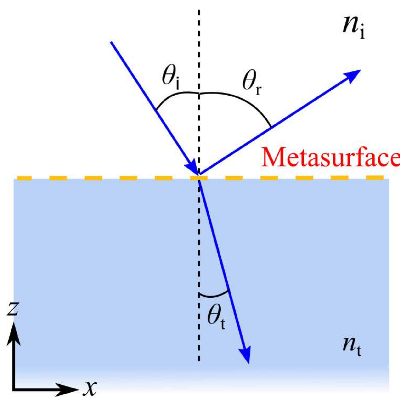
The phase discontinuity or abrupt phase shift at the interface between two media was first introduced by Capasso’s group in 2011, resulting in a generalized Snell’s laws of reflection and refraction [6]. Figure 1 schematically shows a one-dimensional (1D) system used to derive generalized Snell’s laws, where the interface between two media consists of an artificial metasurface introducing a position-dependent phase shift [6]. Considering a plane wave impinging at an angle of , generalized Snell’s laws of reflection and refraction can be written as:
respectively. Here, and are the refractive indexes of the two media, is the wavelength in free space, and and are the reflected and refracted angles, respectively. From Equations (1) and (2), it is evident that the reflected/refracted beam can have an arbitrary direction, provided that a nonzero phase gradient () along the interface is introduced. It should be noted that in the case of , we recover the usual laws of reflection and refraction that imply the conservation of in-plane wave vectors.
To realize metasurfaces with phase discontinuity, V-shaped antenna—which support symmetrical and antisymmetrical electric dipole resonance—were demonstrated to control the reflection and refraction of linearly polarized (LP) light in the infrared range, governed by generalized Snell’s law [6,25]. However, here 2 phase control is achieved with the transmitted/reflected light polarized orthogonal to the incident wave because V-shaped antennae only support electric dipole resonance, which limits the available phase coverage to due to its Lorentz-like polarizabilities [55,56]. Additionally, the polarization conversion efficiency for such single non-magnetic metasurfaces is only 25% for the lossless case [57,58]. To solve these problems, one can design gap-surface plasmon metasurfaces (GSPMs) [26,27,30,59] or use all-dielectric meta-atoms [40,41], which ensure the full control of the phase space with high efficiency while maintaining the polarization state.
2.2. PB-Phase
In the previous examples, phase discontinuity is introduced by varying the meta-atoms’ geometric parameters. Another completely different technique, known as PB-phase or geometric phase, achieves full phase control of the cross-polarized light by using anisotropic meta-atoms with identical geometry, but spatially varying the orientations for circularly polarized (CP) light [60,61,62,63,64,65]. The concept behind PB-phase can be easily revealed by the Jones matrix [66]. In general, the Jones matrix of an anisotropic meta-atom rotated within the x-y plane can be written as:
where and are the reflection (or transmission) coefficients for LP light along the two axes of the anisotropic meta-atom, is the rotated angle with respect to the x-axis, and is the rotation matrix [15]:
When the incident light is CP, the reflected or transmitted light can be written as
where represents the incident left-handed CP (+, LCP) and right-handed CP (−, RCP) light [15,17]. The first term in Equation (5) represents CP light with the same handedness as the incident wave, while the second term stands for CP light with the opposite handedness and gains an additional PB-phase of , whose sign depends on the handedness of the incident light. Thereby, 2 phase coverage can be achieved if the meta-atom is rotated from 0 to 180.
2.3. Stokes Parameters
Before we begin reviewing the recent progress in metasurface-based polarimeters, we briefly introduce the connection between the SOP and the Stokes parameters that are usually measured in experiments [5,67,68]. Consider a monochromatic plane wave that propagates along the z-direction, its electric field can be described by the following Jones matrix:
where and are the amplitude coefficients and is the phase difference between the two components [67,68]. Since conventional detectors only respond to the intensity of the incident light (i.e., ), the phase difference , an important parameter, is inherently difficult to probe experimentally. To remedy this shortcoming of losing the phase information, the Stokes parameters are introduced to fully describe both the amplitude and SOP of a plane wave. Typically, the Stokes parameters are determined by six intensity measurements, which can be written as:
where is the intensity of the analyzed beam, and – contain information on the SOP [67,68]. Additionally, – can be obtained by measuring the intensities of the two orthogonal components in the three basis sets (), ()=, and () = . Here, the basis () corresponds to a rotation of the Cartesian coordinate system () by with respect to the x-axis, while () is the basis for CP light. It should be noted that – are often normalized by so that all possible values are within . Additionaly, one can see that , which shows that the SOPs in three-dimensional (3D) space () can be represented by the so-called Poincaré sphere.
3. Metasurface-Based Polarimeters
Metasurfaces represent an opportunity for polarimetry to overcome bulky and the expensive architectures of conventional volume optics. Here, we try to give an overview of recent progress in metasurface-based polarimeters during the past few years.
3.1. PB-Phase Metasurfaces for Determining Part of the SOP
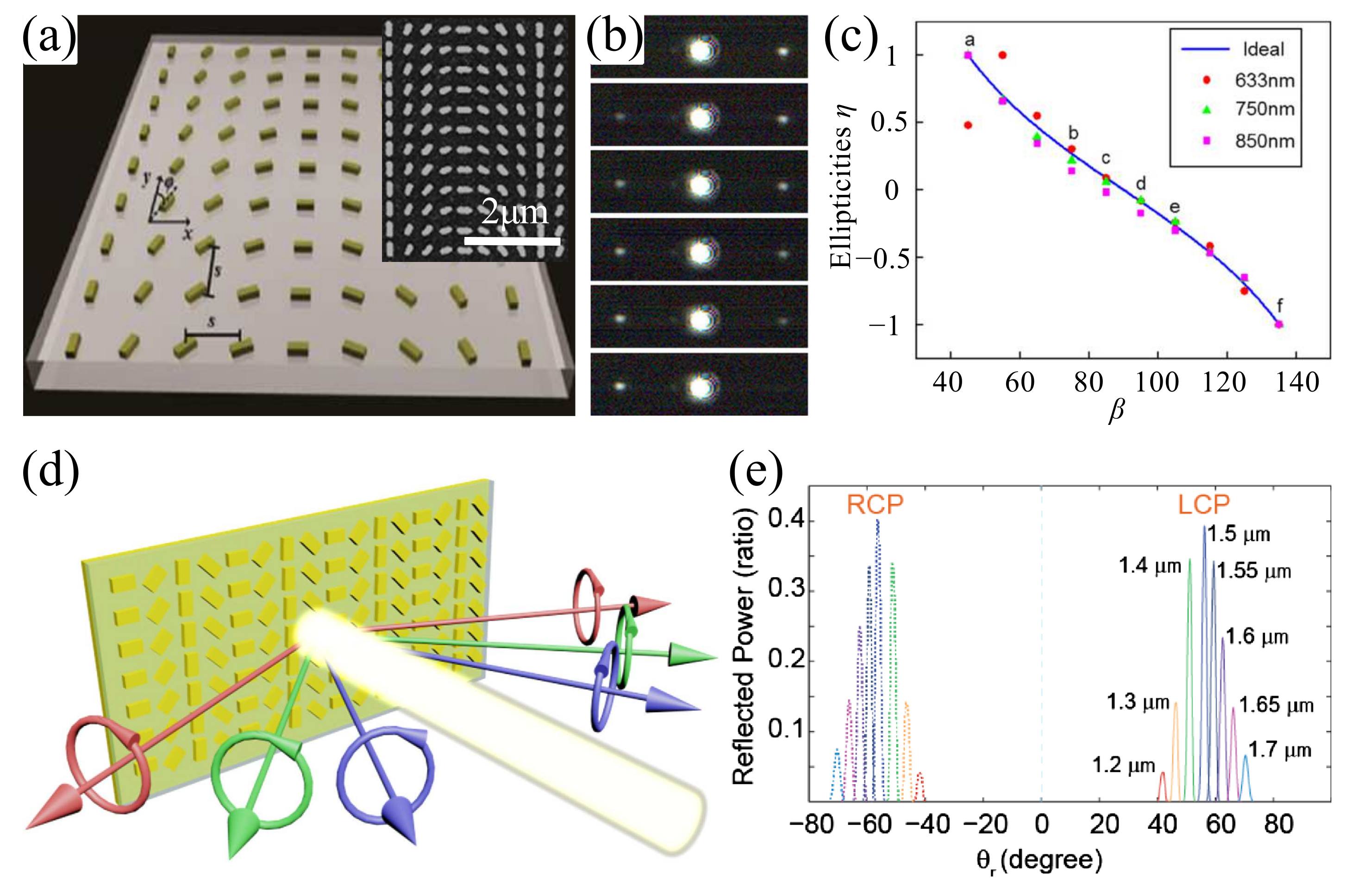
In early approaches, PB-phase metasurfaces together with conventional optical elements, such as polarizers and retardation waveplates, were designed to determine the degree of circular polarization [69,70,71]. One example is depicted in Figure 2a, where an ultrathin (40 nm) gradient metasurface was formed and demonstrated to measure the ellipticity and handedness of polarized light [70]. Figure 2a shows the schematic and scanning electron microscope (SEM) image of the designed PB-phase metasurface, which consists of Au nanorods—with identical geometrical parameters but with spatially varying orientation—on top of anindium tin oxide (ITO) coated glass substrate. The angular orientation of each nanorod varies along the x-direction with an incremental /8 clockwise rotation, but remains invariant in the y-direction. Hence, each period in x-direction contains eight nanorods, resulting in a phase shift ranging from 0 to 2. Due to the spin-selected opposite slope of the PB-phase gradient, the decomposed RCP and LCP beams are steered in opposite directions, exhibiting the photonic spin Hall effect (PSHE) [72]. Thus, the obtained intensity distribution of the anomalously refracted LCP and RCP light provides an accurate and simple method to measure the ellipticity of the incident light. To experimentally demonstrate the capability of determining the degree of circular polarization with the proposed metasurface approach, various polarization states of incident light were impinged on the metasurface by changing the angle between the axis of polarization and the fast axis of the quarter waveplate. These show different intensity distributions after interacting with the metasurface, as shown in Figure 2b. Figure 2c clearly shows that the ellipticity and handedness of various incident polarization states can be well characterized, and are in good agreement with the predicted values. Additionally, the proposed method here is suitable to work at a wide range of wavelengths, ascribed to the broadband nature of PB-phase. It should be noted that the conversion efficiency of the metasurface is strictly limited and the maximum conversion efficiency is around 7.6% at 940 nm, which may affect the performance of the proposed metasurface since the ellipticity and handedness of various incident polarization states are determined by the intensities of the refracted beams. The limited efficiency is ascribed to the single electric dipole resonance supported by the non-magnetic Au nanorods on top of ITO-coated glass substrate, which sets the upper bound of the coupling efficiency between the two polarizations to be 25% in the limit of negligible absorption [57,58].
PB-phase GSPM have been demonstrated to increase the efficiency [71]. Figure 2d presents a novel and compact circular dichroism (CD) spectrometer based on PB-phase GSPM, which utilizes PSHE in reflection. Specifically, an array of anisotropic elements is used to achieve different phase gradients in response to LCP and RCP light. Therefore, the spin components of the incident broadband source are reflected in opposite directions, and the reflection angle of each wavelength component is varied according to generalized Snell’s law [6]. When a broadband light source is incident on the metasurface, the LCP and RCP spectra are spatially separated and can be recorded simultaneously, which eliminates the need of switching the incident polarization, as shown in Figure 2e. By analyzing the spectra of different spin components, the CD of the light source can be easily obtained, which can serve as an important tool in sensing chiral molecules. Additionally, there is no other hardware required for this type of CD spectrometry.
As a final comment, it is worth pointing out that the obtained SOP of the incident light is incomplete as this type of PB-phase metasurface-based chiroptical spectroscopy has only two channels and cannot probe the polarization azimuthal angle. To fully characterize the SOP and determine the Stokes parameters, an additional polarizer is needed, which will inevitably increase the complexity of the whole system.
3.2. Metasurface-Only Polarimeters
In recent years, on-chip metasurface-only polarimeters have been proposed and were demonstrated to determine the entire SOP simultaneously. These polarimeters involve different configurations, including gap surface plasmon resonators [67,73], metallic nanoantennas [74,75], and all-dielectric nanoposts [76].
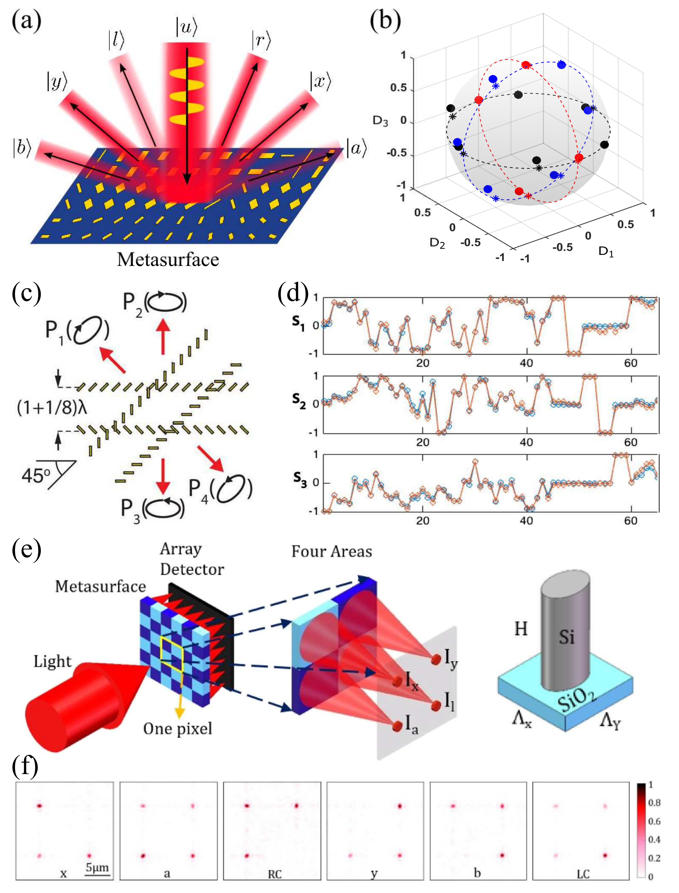
Starting with GSPMs, Figure 3a conveniently illustrates the basic working principle of the metagrating-based polarimeter, composed of three interweaved metasurfaces. An arbitrary polarized incident beam is spatially diffracted into six different directions, corresponding to different polarization states, since each metasurface functions as a polarization splitter for a certain polarization basis (,), (,), or (,) [67]. As such, the proposed metagrating responds uniquely to all possible polarization states and the most pronounced differences in the corresponding diffractions occur for the six extreme polarizations , , , , , and . Hence, the entire SOP can be determined. By conducting simultaneous measurements of the corresponding far-field diffraction intensities in the six predesigned directions, the Stokes parameters can be quickly retrieved, thereby allowing one to easily analyze the SOP of the incident light. At the design wavelength of 800 nm, the experimental diffraction contrasts obtained by averaging three successive measurements are in good agreement with the input Stokes parameters, and lay on the Poincaré sphere, with points covering all octants of the 3D parameter space (Figure 3b). The two-norm deviation between Stokes parameters and experimental diffraction contrasts is estimated to be around ∼0.1, which can be significantly reduced with better fabrication facilities. Importantly, due to the rather broadband response of the GSPM, the designed metagrating could work over a wide wavelength range. In the wavelength range of 750–850 nm, there is no significant degradation of the metagrating performance observed in the experiments; the experimentally diffraction contrasts closely represent the Stokes parameters.
In a later work [74], an ultracompact in-line polarimeter was demonstrated for transmission-type polarimetry by using a two-dimensional (2D) metasurface made up of a thin array of subwavelength metallic antennae embedded in a polymer film (Figure 3c). By placing two pairs of gold nanorod rows superimposed at a 45 relative angle, incident beams with four elliptical polarization states are directionally scattered. Based on the measured polarization-selective directional scattering in four directions from the corresponding out-coupling gratings, the SOP could be precisely obtained after calibration. From Figure 3d, one can clearly see that the measurement of several arbitrarily selected polarizations using the metasurface polarimeter agrees well with the result from the commercial polarimeter at a wavelength of 1550 nm. Considering the potential compactness, speed, and stability, this design is clearly superior to the commercial polarimeter. Following this concept, a compact fiber-coupled polarimeter with high sampling rates wasdemonstrated [75]. Here, we note that the degree of polarization (DOP) cannot be measured in the present four-output design. For DOP measurements, a more complex antenna array design is needed [74].
As complementary to compact polarimeters with plasmonic metasurfaces, all-dielectric metasurfaces may be tailored to design ultracompact polarimeters [76]. Compared with the GSPM-based polarimeters, such all-dielectric polarimeters could relax the difficulty of system integration as it is operating in transmission-mode, while maintaining high efficiency due to the relatively high refractive index and negligible absorption [22]. One example of a dielectric metasurface integrated polarimeter is depicted in Figure 3e, which contains a silicon metasurface and array detector with a distance of 4.2 m corresponding to the focal plane of the metasurface. The metasurface consists of multiple pixels, where each pixel has four different areas containing periodically arranged elliptical silicon pillars resting on a silica substrate. Within the pixel, each area functions as a polarization-sensitive focusing lens, separating four polarization components from the incident light and focusing them to the detector’s surface. Upon the excitation of a normally incident beam with arbitrary SOP, four focal spots are generated in the focal plane, which show different intensity distributions for different polarizations, as shown in Figure 3f. By detecting the intensities of the focused four polarization components in the focal plane ( , , , and , which refer to the intensities of horizontal (H), vertical (V), +45, and LCP components, respectively) and carefully calibrating the system, the Stokes parameters can be retrieved to fully describe the SOP of the incident light. Since each part of the incident light is fully used to determine the SOP, the detection efficiency only depends on the focusing efficiency of each flat focusing lens, which is theoretically estimated to be above 60%.
3.3. Metacoupler-Based Polarimeter
Inspired by the polarization-controlled unidirectional excitation of surface plasmon polaritons (SPPs) [33], Pors et al. suggested a metasurface-based polarimeter that can effectively couple normally incident light to in-plane plasmonic waveguide modes. By calculating the relative efficiency of excitation between predefined propagation directions, the incident SOP can be directly retrieved. Similar to the work in Reference [68], three properly designed GSPMs made up of metal-insulator-metal (MIM) nanoantennae embedded in a polymer layer were incorporated to make the so-called waveguide metacoupler, as depicted in Figure 4a,b. This metacoupler unidirectionally excites the plasmonic waveguide modes instead of far-field reflection propagating in six different directions for the three polarization basis sets—(,), (,), and (,)—dictated by the definition of the Stokes parameters. Figure 4c–e displays the intensity distributions in an area of m for three extreme SOPs, namely, , and polarizations, thereby illustrating all-polarization sensitivity. It is obvious that the metacoupler can launch the waveguide modes propagating in the six designed directions. Additionally, the power distribution in the six channels are strongly polarization-dependent and one of the six channels is suppressed depending on the input SOP. For example, port #1 is greatly suppressed for polarization (Figure 4c) while port #4 becomes weak when the polarization is switched to (Figure 4d). By integrating the power flows of the waveguide modes at the ports marked in Figure 4c, all the coupling efficiencies can be calculated, through which the normalized contrast denoted – is determined. Here it should be noted that, unlike the previous work [67], there is no direct mathematical equivalence between – and –, thus the retrieved contrasts can only roughly represent the input Stokes parameters. In order to achieve the best performance of the polarimeter, one needs to properly relate the six coupling efficiencies to the three Stokes parameters with calibration. After calibration, the proposed in-plane polarimeter shows excellent performance, with the retrieved results perfectly overlapping with the Stokes parameters, as displayed in Figure 4f.
3.4. Metasurfaces Spectropolarimeters
In addition to determining the SOP of an incident beam, spectral analysis is concomitantly required. This resulted in the recent developments of metasurface-based spectropolarimeters, which enable simultaneous measurements of the spectrum and SOP [77,78,79,80]. As such, the spectropolarimeters are superior to the isolated spectrometers or polarimeters, regarding their capability of combining the uncorrelated information channels of intensity, wavelength, and SOP together.
Starting with segmented spectropolarimeters [77,78], a spectropolarimeter metadevice that steers different polarization and spectral components into predesigned spatial directions was proposed [77], which consists of six GSPMs arranged in a array, corresponding to horizontal (), vertical (), , RCP, and LCP analyzers. Once a probe beam with a certain polarization state is incident on the metadevice, six diffraction spots are generated in the far-field, resulting from the anomalous reflection of each GSPM area. When the incident polarization is altered, the relative intensity distributions of diffraction spots change accordingly. As such, the polarization response of this spectropolarimeter at a given wavelength can be determined by carefully analyzing the relationship between the intensity of individual peaks and the incident SOP. Additionally, this metadevice could be used to analyze the wavelength due to the fact that the GSPMs are usually dispersive. The measured angular dispersion for the LCP and RCP channels are 0.053 /nm and 0.024 /nm, respectively. Hence, proving the potential of spectral measurement with spectral resolution up to ∼0.3 nm if this metadevice is inserted into a typical spectrometer setup. It should be noted that the spectral resolution of ∼0.3 nm is estimated with the aid of other optical components in a commercial spectrometer and the intrinsic resolution accessed with the metadevice itself is rather limited.
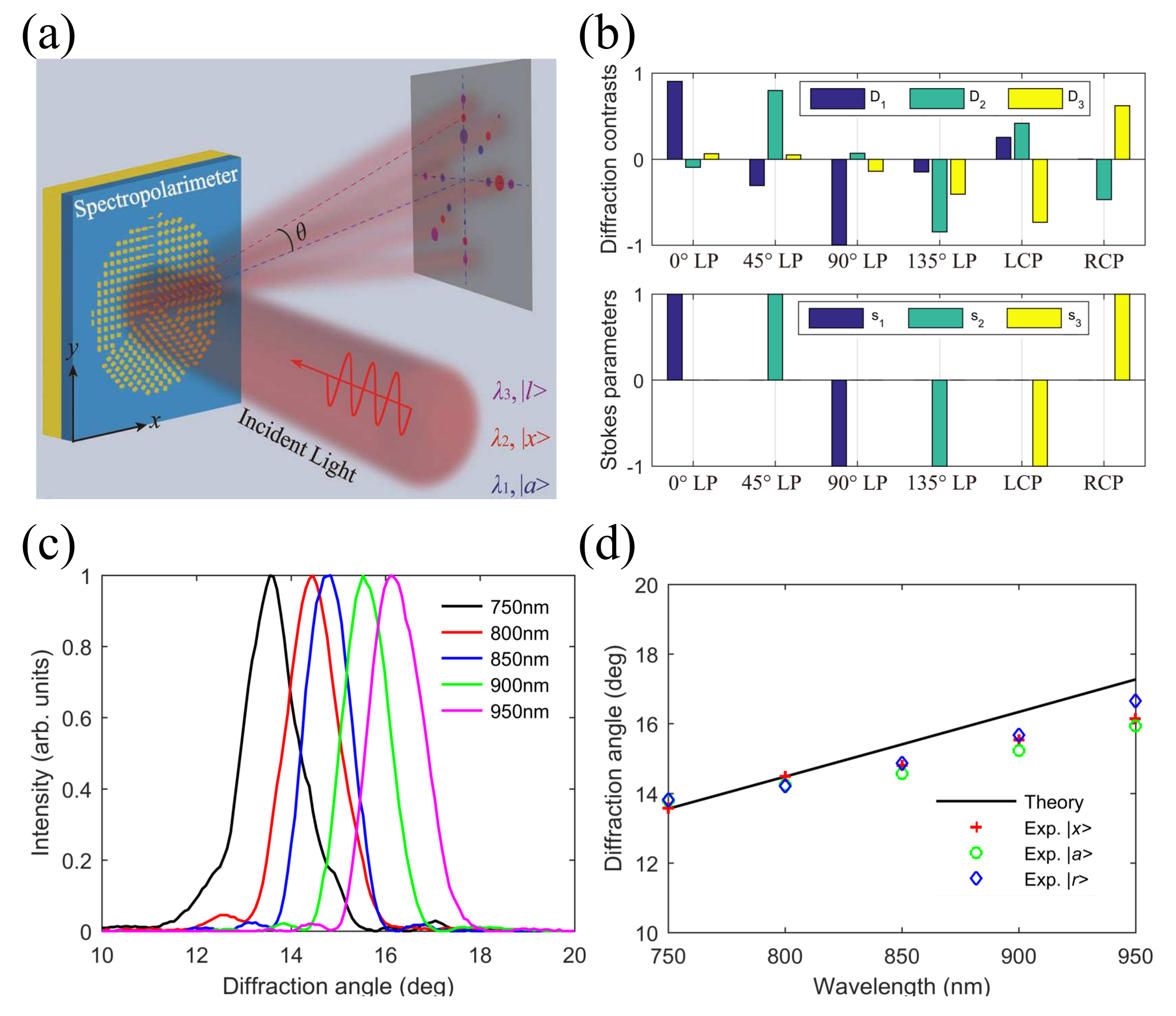
Although the metadevice with rectangular configuration shows good performance, it is relatively sensitive to the illuminated area by the incident light. In particular, the incident light should cover the whole area of the metasurface with the same light intensity in order to ensure faithful comparison of the corresponding diffraction orders. To increase the detection robustness and the compatibility with a circular laser beam that has a Gaussian profile, a segmented plasmonic spectropolarimeter has been demonstrated by using a center-symmetric configuration, featuring a self-calibrating nature [78]. The working principle of the self-calibrated spectropolarimeter is displayed in Figure 5a, which consists of three diffident types of GSPMs occupying circular sectors each. Similar to the previous work [67], each sector-shaped GSPM operates as an efficient polarization splitter for one of the three polarization bases (,), (,), and (,). Upon the excitation of a normally incident monochromatic beam, this center-symmetrical configuration would diffract any normally incident beam to six predesigned directions, whose contrasts in the corresponding diffraction intensities would provide a direct measure of the SOP and retrieval of the associated Stokes parameters, due to the direct mathematical equivalence between the normalized contrasts and Stokes parameters. At the same time, the polar angle of diffraction is approximately proportional to the wavelength, resulting in the spectral analysis of the incident beam. The fabricated 96 m diameter spectropolarimeters, operating in the wavelength range of 750–950 nm, are found to exhibit excellent capability of polarization detection (Figure 5b). Moreover, the experimentally measured angular dispersion for the channel is 0.0133 /nm, corresponding to a measured spectral resolving power of (Figure 5c,d). Importantly, due to the circular-sector design, polarization analysis can be conducted for optical beams of different diameters without prior calibration, thereby demonstrating the beam-size invariant functionality. As a final comment, we would like to stress that uneven illumination of the three metasurfaces caused by misalignment or inhomogeneity of the laser beam will not affect the retrieved Stokes parameters and no calibration is needed since the Stokes parameters are only related to the relative diffraction contrasts for three polarization bases.
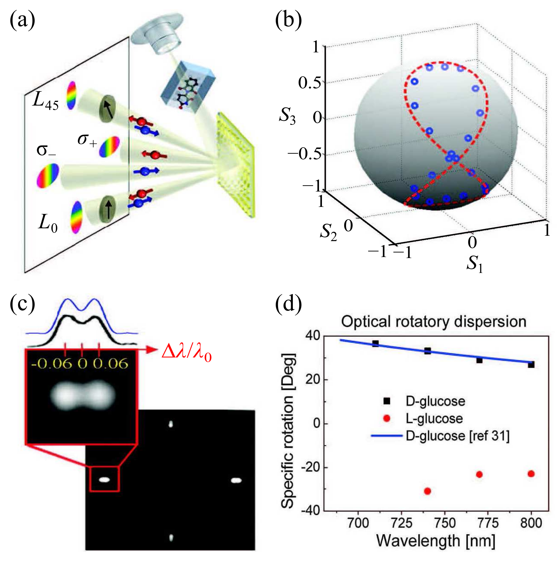
To increase the spectral resolution of spectropolarimeters, interleaved metasurfaces have been designed to conduct spectropolarimetry, where different channels share the aperture of the device [79,80]. A good example of interleaved metasurface-based spectropolarimeters is shown in Figure 6a, where three linear phase profiles associated with different nanoantenna subarrays, formed by the random interspersing, make up the configuration. This enables simultaneous characterization of the SOP and spectrum in the reflected beam [79]. In particular, by randomly mixing optical nanoantenna arrays with different phase functions, the PB-phase concept, spatially interleaved phase profiles are designed, which yield extraordinary information capability. When a probe beam with an arbitrary SOP is incident on the spectropolarimeter metasurface (SPM), two beams of intensities and , consisting of opposite helicity states, and two additional beams emerge. The latter two beams are projected onto linear polarizers at 0 and 45, determining the linearly polarized components and , respectively. The Stokes parameters of the incident beam are then calculated with a calibration experiment. Figure 6b shows the measured and calculated Stokes parameters on a Poincaré sphere for an analyzed beam impinging the SPM at a wavelength of 760 nm with different polarizations, demonstrating the excellent capability of the polarization probe. Furthermore, such interleaved SPM shows good spectral resolving power, which was measured to be when the diameter is only 50 m (Figure 6c). To further improve the spectral resolving power while keeping the aperture size fixed, super-dispersive, off-axis metalenses that could simultaneously disperse and focus light of different wavelengths can be used [81,82]. Based on this SPM, the optical rotatory dispersion (ORD) for the specific rotations of d-glucose (chiral molecule) and its enantiomer l-glucose were measured. The ORD of d-glucose shows good agreement with the values found in the literature and the l-glucose ORD is manifested by the opposite behavior as expected (Figure 6d). Finally, we note that this interleaved center-symmetrical approach can be applied with dielectric metasurfaces for spectropolarimetry operating in the visible wavelength range [80].
3.5. On-Chip Spectropolarimetry by Fingerprinting with Random Metasurfaces
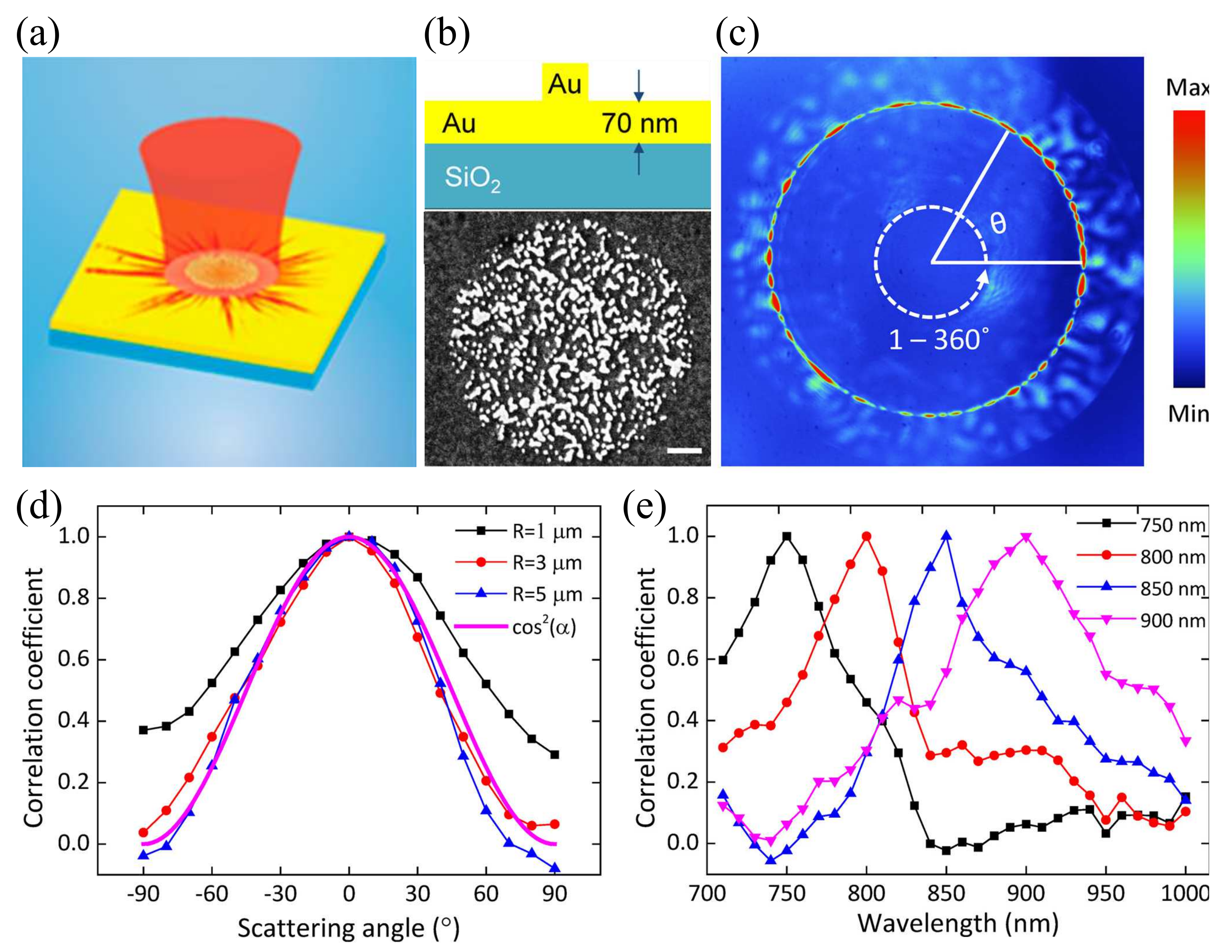
Metasurfaces composed of disordered structure have been demonstrated to realize various functions, such as diffusing light [29], absorbing light [83], waveguiding [84], wavefront shaping [85,86,87], and polarimetry [88]. In Reference [88], a unique on-chip spectropolarimeter, by fingerprinting with a random gold nanoparticle (NP) array, in the near-infrared range is presented. This spectropolarimeter is based on analyzing scattering SPP patterns from micron-sized circular arrays of randomly distributed gold NPs (Figure 7a) through a leakage radiation microscope (LRM). Due to strong multiple scattering and the countless scattering routes between the closely packed NPs, the disordered media is able to generate unique and complicated scattering patterns that are sensitive to the wavelength and SOP, and thereby those scattering spectra can be employed as spectropolarimetric fingerprints to distinguish incident light carrying different polarization and spectrum components. The random metasurface consists of gold NPs with diameter of about 50 nm, thickness of 70 nm, and density of 75 m, distributed in circular areas with radii of 1–5 m on top of a 70 nm thick gold film and 170 m thick silica substrate (Figure 7b). Larger array sizes generate more complex scattering patterns.
In the experiment, the angular spectra of the scattering patterns are characterized along the azimuthal angle through their Fourier plane images from the LRM (Figure 7c). The scattering spectra of different SOPs and wavelengths are quantitatively compared by calculating the correlation coefficients. The experimental results shows a substantial difference between the main SOPs: the orthogonal SOPs (horizontal and vertical linear, or left and right circular) exhibit virtually no correlation (<0.2). They also investigated the influence of the angle () between two different linear polarizations, and the correlation coefficient exhibits similar angular dependence as the analytical expression of the polarizer transmission (cos) with the increasing polarization angle difference (Figure 7d). In the case of varying wavelengths, the correlation coefficient also drops accordingly with increasing wavelength difference in the 700–1000 nm range, with the wavelength selectivity estimated to be / ( is the propagation length of the SPP) (Figure 7e). Numerical simulations of angular SPP scattering spectra are also carried out and confirm the sensitivity of the SPP scattering spectra to different wavelength and SOPs, thereby validating the proposed concept of on-chip spectropolarimetry by fingerprinting based on SPP excitation and multiple scattering by random surface nanostructures. Compared to other metasurface-based polarimetry, the fingerprinting approach might require extra work for the careful calibration; the registration of different SPP scattering spectra to create a database of spectropolarimetric fingerprints. However, it also has the advantage of simple design and fabrication procedure, in addition to its potential applications for optical wavefront sensing, optical beam tracing and positioning, and so on.
3.6. Metasurface OAM Spectropolarimeters
Besides the spectrum and polarization, the orbital angular momentum (OAM) is also an intrinsic property of light, which processes a helical phase front, such that the Poynting vector within the beam is twisted with respect to the principal axis of light propagation [89]. In contrast to the spin angular momentum (SAM) that can take only two values, OAM is unbounded since the topological charge l can take any integer value. Thus OAM beams have recently gained tremendous interest in optical trapping, high-resolution microscopy, and quantum information processing, as they introduces an additional degree of freedom for encoding the light beam and increasing communication capabilities [20,90]. A variety of metasurfaces have been demonstrated to generate OAM beams [20,91,92,93,94], which have, in turn, motivated the implementation of OAM polarimetry, enabling direct detection of topological changes to a structured optical wavefront. Very recently, Hasman’s group incorporated spectropolarimetry and OAM sensing into a silicon metasurface, which would ultimately facilitate a simultaneous detection of the wavelength, polarization, and OAM of light by projecting an incident mode on a set of orthogonal OAM states [80].
The OAM spectropolarimeter metasurface (OSPM), designed with the combination of the shared-aperture and PB-phase concepts, consists of interleaved antenna sub-arrays with multiplexed geometric-phase profiles. These result in a finite number of dominant multiplexed OAM harmonic orders with identical intensities. Illuminating the OSPM with an arbitrarily polarized polychromatic light source results in four symmetric sets of annular spots with a bright spot at the center, as shown in Figure 8a. Given an incident beam possessing an arbitrary topological charge , the winding numbers of the diffracted orbital harmonics are modified by accumulating the value of . This shifts the bright spot from its original location to , thus enabling the determination of the incident OAM value (Figure 8b–g). From the far-field images, one can clearly see that the position of the bright spot changes in response to alternating the incident OAM. For instance, the bright spot moves to the right side if the incident OAM carries a topological change of (Figure 8c), while the bright spot moves to the left side if (Figure 8e). Additionally, such OSPM can resolve the incident polarization states and wavelengths precisely.
3.7. Photodetector Integrated Polarimeters
In the previous sections, the SOPs are mainly determined by the measured optical signals. An as-yet unexplored milestone in the field of metasurface-based polarimeters is to achieve an integrated electronic device, which can electronically probe the polarization states. Owing to the fascinating properties of metasurfaces, several photodetector integrated polarimeters have been proposed and demonstrated by integrating meta-atoms with semiconductor elements [95,96]. In this section, we will review some of the recent progress in photodetector integrated polarimeters.
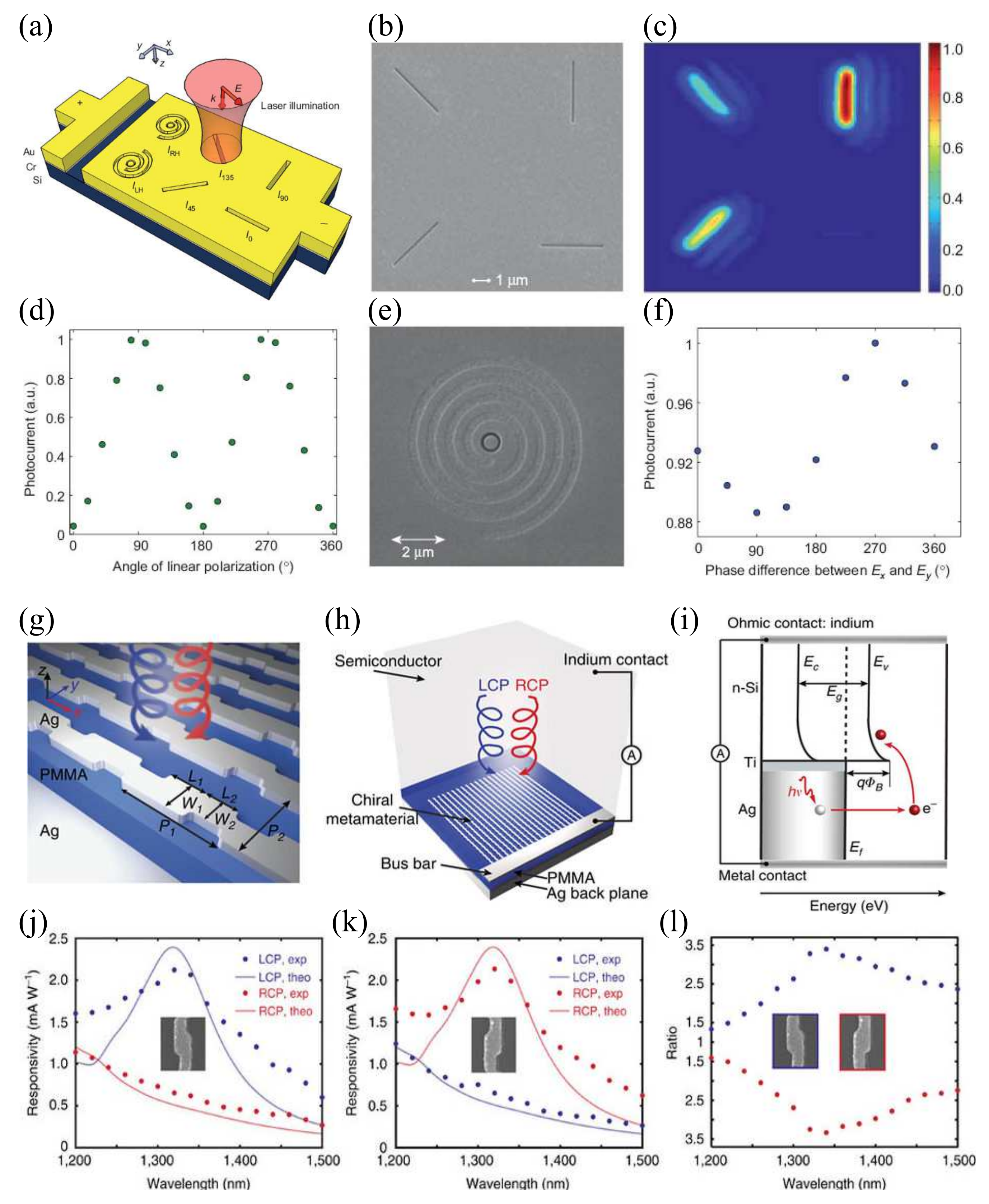
As a good example, Figure 9a schematically shows a silicon photodetector integrated with a set of plasmonic structures that can be used as either a broadband linear-Stokes polarimeter or a narrowband full-Stokes polarimeter, capable of determining the complete state of polarization of a light beam [95]. Specifically, in this silicon-based Schottky detector, the Schottky barrier is created by using a few nanometer thick chromium layer between the n-type silicon substrate and the gold layer. The gold contact is patterned with four linear subwavelength slits at different orientations and two subwavelength coaxial apertures surrounded by spiral grooves with opposite twists, which have different optical responses to the incident polarizations. In this way, these differently shaped plasmonic structures patterned in the Au film can work as the polarization filters for the six extreme polarizations (, , , , and ). Given the linear relationship between the generated photocurrent and the light intensity behind the filters in the silicon substrate, the required intensity measurements can effectively be translated into a set of photocurrent measurements. Figure 9b shows the fabricated linear Stokes detector in which four linear slits are milled into the gold film with focused ion beam (FIB) milling. By raster scanning the laser beam over the device, the photocurrent images of the linear Stokes detector at nm are obtained, confirming that the light absorption in the silicon is dominated by the portion of the light polarized normal to each slit (Figure 9c). The photocurrent response of a single slit at a given polarization is defined as the maximum measured photocurrent found in scanning the beam over the slit. If the direction of the incident electric field is continuously varied with a half wave plate, the photocurrent response of a single slit changes accordingly, revealing the linear polarization-dependent response of the slit, as shown in Figure 9d. Therefore the arrangement of four slits can be used for linear Stokes polarimetry with which one can distinguish between linear, circular, and elliptical states of polarization and determine the degree of linear polarization for partially polarized light over a broadband wavelength range. To determine the handedness of a circularly or elliptically polarized light and also degree of circular polarization for partially polarized light, two subwavelength coaxial apertures surrounded by spiral grooves with opposite twists have been designed, which respond differently to CP light of opposite handedness due to geometric phase effects (Figure 9e,f) [97,98].
Very recently, a CP light detector was demonstrated by combining a chiral metasurface with hot electron injection, enabling a potential application for polarimetry [96]. As shown in Figure 9g, the proposed chiral metasurface—consisting of the chiral plasmonic meta-atom array, dielectric spacer, and metal backplane—can perfectly absorb CP light with one particular handedness while largely reflecting the opposite component. Within the metasurface, the continuous ’Z’-shaped silver antenna allows for an electrical connection with a silver bus serving as the electrode (Figure 9h). The whole device is realized by placing an n-type silicon wafer in contact with the antenna layer, forming a Schottky barrier, as shown in Figure 9i. As such, the device can selectively generate hot electrons and produce a photocurrent signal depending on the handedness of light. By illuminating the metasurfaces with a CP laser and measuring photocurrent as a function of the laser handedness and wavelength, the photoresponse spectra of the devices were obtained (Figure 9j,k). In general, the photoresponsivity spectrum matches well with the measured absorption spectrum. When the metasurface is left-handed, it absorbs LCP light and reflects RCP light, resulting in dominating photoresponsivity for LCP light. Once the handedness is switched to right, it generates a stronger current signal for RCP light. Furthermore, the large distinction in the photocurrent for LCP and RCP light corresponds to the large CD (Figure 9l). Therefore, by including both right-handed and left-handed surface patterns, the sensor can differentiate between LCP and RCP light.
4. Conclusions and Outlook
We have overviewed the rapid development of metasurface-based polarimeters. From the perspectives of physical mechanisms, the concepts of generalized Snell’s law, PB-phase, and Stokes parameters were introduced. After that, we reviewed the efforts of metasurface-based polarimeters, including generic polarimeters, spectropolarimeters, OAM spectropolarimeters, and photodetector integrated polarimeters.
Although much progresses has been achieved in the field of metasurface-based polarimeters, there are still some challenges to overcome in future. To date, most of metasurface-based polarimeters destroy or substantially modify the original wavefronts of an incident beam in the detection process. Therefore, a nondestructive and real-time polarimeter is desired, which leaves the original wavefronts virtually unaffected [99]. Additionally, nanofabrication of the metasurface-based polarimeters mainly relies on high-cost and time-consuming electron beam lithography or FIB milling, which may hinder the potential applications of metasurface optical devices. Nanoimprinting should be a feasible way to the low cost and large area fabrication of metasurfaces [100].
References
Acknowledgments
This work was funded by the European Research Council (the PLAQNAP project, Grant 341054) and the University of Southern Denmark (SDU2020 funding).
Author Contributions
Fei Ding and Yiting Chen contributed to writing and finalizing the paper. Sergey I. Bozhevolnyi supervised the project.
Conflicts of Interest
The authors declare no conflict of interest.
References
- Born, M.; Wolf, E. Principles of Optics: Electromagnetic Theory of Propagation, Interference and Diffraction of Light; Elsevier: New York, NY, USA, 2013. [Google Scholar]
- Sterzik, M.F.; Bagnulo, S.; Palle, E. Biosignatures as revealed by spectropolarimetry of Earthshine. Nature 2012, 483, 64–66. [Google Scholar] [CrossRef] [PubMed]
- Gupta, N. Acousto-optic-tunable-filter-based spectropolarimetric imagers for medical diagnostic applications—Instrument design point of view. J. Biomed. Opt. 2005, 10, 051802. [Google Scholar] [CrossRef] [PubMed]
- Tyo, J.S.; Goldstein, D.L.; Chenault, D.B.; Shaw, J.A. Review of passive imaging polarimetry for remote sensing applications. Appl. Opt. 2006, 45, 5453–5469. [Google Scholar] [CrossRef] [PubMed]
- Bohren, C.F.; Huffman, D.R. Absorption and Scattering of Light by Small Particles; Wiley-VCH Verlag GmbH: Weinheim, Germany, 2004. [Google Scholar]
- Yu, N.; Genevet, P.; Kats, M.A.; Aieta, F.; Tetienne, J.P.; Capasso, F.; Gaburro, Z. Light Propagation with Phase Discontinuities: Generalized Laws of Reflection and Refraction. Science 2011, 334, 333–337. [Google Scholar] [CrossRef] [PubMed]
- Yu, N.; Capasso, F. Flat optics with designer metasurfaces. Nat. Mater. 2014, 13, 139–150. [Google Scholar] [CrossRef] [PubMed]
- Meinzer, N.; Barnes, W.L.; Hooper, I.R. Plasmonic meta-atoms and metasurfaces. Nat. Photon. 2014, 8, 889–898. [Google Scholar] [CrossRef] [Green Version]
- Koenderink, A.F.; Alù, A.; Polman, A. Nanophotonics: Shrinking light-based technology. Science 2015, 348, 516–521. [Google Scholar] [CrossRef] [PubMed]
- Luo, X.; Pu, M.; Ma, X.; Li, X. Taming the Electromagnetic Boundaries via Metasurfaces: From Theory and Fabrication to Functional Devices. Int. J. Antennas Propag. 2015, 2015, 204127. [Google Scholar] [CrossRef]
- Minovich, A.E.; Miroshnichenko, A.E.; Bykov, A.Y.; Murzina, T.V.; Neshev, D.N.; Kivshar, Y.S. Functional and nonlinear optical metasurfaces. Laser Photon. Rev. 2015, 9, 195–213. [Google Scholar] [CrossRef]
- Shaltout, A.M.; Kildishev, A.V.; Shalaev, V.M. Evolution of photonic metasurfaces: From static to dynamic. J. Opt. Soc. Am. B 2016, 33, 501–510. [Google Scholar] [CrossRef]
- Zhang, L.; Mei, S.; Huang, K.; Qiu, C.W. Advances in Full Control of Electromagnetic Waves with Metasurfaces. Adv. Opt. Mater. 2016, 4, 818–833. [Google Scholar] [CrossRef]
- Glybovski, S.B.; Tretyakov, S.A.; Belov, P.A.; Kivshar, Y.S.; Simovski, C.R. Metasurfaces: From microwaves to visible. Phys. Rep. 2016, 634, 1–72. [Google Scholar] [CrossRef]
- Chen, H.T.; Taylor, A.J.; Yu, N. A review of metasurfaces: Physics and applications. Rep. Prog. Phys. 2016, 79, 076401. [Google Scholar] [CrossRef] [PubMed]
- Hsiao, H.H.; Chu, C.H.; Tsai, D.P. Fundamentals and Applications of Metasurfaces. Small Methods 2017, 1, 1600064. [Google Scholar] [CrossRef]
- Ding, F.; Pors, A.; Bozhevolnyi, S.I. Gradient metasurfaces: A review of fundamentals and applications. Rep. Prog. Phys. 2018, 81, 026401. [Google Scholar] [CrossRef] [PubMed]
- Yu, N.; Genevet, P.; Aieta, F.; Kats, M.A.; Blanchard, R.; Aoust, G.; Tetienne, J.P.; Gaburro, Z.; Capasso, F. Flat Optics: Controlling Wavefronts With Optical Antenna Metasurfaces. IEEE J. Sel. Top. Quantym Electron. 2013, 19, 4700423. [Google Scholar]
- Hum, S.V.; Perruisseau-Carrier, J. Reconfigurable Reflectarrays and Array Lenses for Dynamic Antenna Beam Control: A Review. IEEE Trans. Antennas Propag. 2014, 62, 183–198. [Google Scholar] [CrossRef]
- Guanghao, R.; Qiwen, Z. Tailoring optical complex fields with nano-metallic surfaces. Nanophotonics 2015, 4, 2–25. [Google Scholar]
- Estakhri, N.M.; Alù, A. Recent progress in gradient metasurfaces. J. Opt. Soc. Am. B 2016, 33, A21–A30. [Google Scholar] [CrossRef]
- Jahani, S.; Jacob, Z. All-dielectric metamaterials. Nat. Nanotechnol. 2016, 11, 23–36. [Google Scholar] [CrossRef] [PubMed]
- Zheludev, N.I.; Kivshar, Y.S. From metamaterials to metadevices. Nat. Mater. 2012, 11, 917–924. [Google Scholar] [CrossRef] [PubMed]
- Genevet, P.; Capasso, F. Holographic optical metasurfaces: A review of current progress. Rep. Prog. Phys. 2015, 78, 024401. [Google Scholar] [CrossRef] [PubMed]
- Ni, X.; Emani, N.K.; Kildishev, A.V.; Boltasseva, A.; Shalaev, V.M. Broadband Light Bending with Plasmonic Nanoantennas. Science 2012, 335, 427. [Google Scholar] [CrossRef] [PubMed]
- Sun, S.; Yang, K.Y.; Wang, C.M.; Juan, T.K.; Chen, W.T.; Liao, C.Y.; He, Q.; Xiao, S.; Kung, W.T.; Guo, G.Y.; et al. High-Efficiency Broadband Anomalous Reflection by Gradient Meta-Surfaces. Nano Lett. 2012, 12, 6223–6229. [Google Scholar] [CrossRef] [PubMed]
- Pors, A.; Albrektsen, O.; Radko, I.P.; Bozhevolnyi, S.I. Gap plasmon-based metasurfaces for total control of reflected light. Sci. Rep. 2013, 3, 2155. [Google Scholar] [CrossRef] [PubMed] [Green Version]
- Pfeiffer, C.; Grbic, A. Metamaterial Huygens’ Surfaces: Tailoring Wave Fronts with Reflectionless Sheets. Phys. Rev. Lett. 2013, 110, 197401. [Google Scholar] [CrossRef] [PubMed]
- Pors, A.; Ding, F.; Chen, Y.; Radko, I.P.; Bozhevolnyi, S.I. Random-phase metasurfaces at optical wavelengths. Sci. Rep. 2016, 6, 28448. [Google Scholar] [CrossRef] [PubMed] [Green Version]
- Sun, S.; He, Q.; Xiao, S.; Xu, Q.; Li, X.; Zhou, L. Gradient-index meta-surfaces as a bridge linking propagating waves and surface waves. Nat. Mater. 2012, 11, 426–431. [Google Scholar] [CrossRef] [PubMed]
- Lin, J.; Mueller, J.B.; Wang, Q.; Yuan, G.; Antoniou, N.; Yuan, X.C.; Capasso, F. Polarization-controlled tunable directional coupling of surface plasmon polaritons. Science 2013, 340, 331–334. [Google Scholar] [CrossRef] [PubMed]
- Huang, L.; Chen, X.; Bai, B.; Tan, Q.; Jin, G.; Zentgraf, T.; Zhang, S. Helicity dependent directional surface plasmon polariton excitation using a metasurface with interfacial phase discontinuity. Light Sci. Appl. 2013, 2, e70. [Google Scholar] [CrossRef]
- Pors, A.; Nielsen, M.G.; Bernardin, T.; Weeber, J.C.; Bozhevolnyi, S.I. Efficient unidirectional polarization-controlled excitation of surface plasmon polaritons. Light Sci. Appl. 2014, 3, e197. [Google Scholar] [CrossRef]
- Sun, W.; He, Q.; Sun, S.; Zhou, L. High-efficiency surface plasmon meta-couplers: Concept and microwave-regime realizations. Light Sci. Appl. 2016, 5, e16003. [Google Scholar] [CrossRef]
- Ding, F.; Deshpande, R.; Bozhevolnyi, S.I. Bifunctional gap-plasmon metasurfaces for visible light: Polarization-controlled unidirectional surface plasmon excitation and beam steering at normal incidence. Light Sci. Appl. 2018, 7, e17178. [Google Scholar]
- Li, X.; Xiao, S.; Cai, B.; He, Q.; Cui, T.J.; Zhou, L. Flat metasurfaces to focus electromagnetic waves in reflection geometry. Opt. Lett. 2012, 37, 4940–4942. [Google Scholar] [CrossRef] [PubMed]
- Aieta, F.; Genevet, P.; Kats, M.A.; Yu, N.; Blanchard, R.; Gaburro, Z.; Capasso, F. Aberration-Free Ultrathin Flat Lenses and Axicons at Telecom Wavelengths Based on Plasmonic Metasurfaces. Nano Lett. 2012, 12, 4932–4936. [Google Scholar] [CrossRef] [PubMed]
- Ni, X.; Ishii, S.; Kildishev, A.V.; Shalaev, V.M. Ultra-thin, planar, Babinet-inverted plasmonic metalenses. Light Sci. Appl. 2013, 2, e72. [Google Scholar] [CrossRef]
- Pors, A.; Nielsen, M.G.; Eriksen, R.L.; Bozhevolnyi, S.I. Broadband Focusing Flat Mirrors Based on Plasmonic Gradient Metasurfaces. Nano Lett. 2013, 13, 829–834. [Google Scholar] [CrossRef] [PubMed]
- Arbabi, A.; Horie, Y.; Bagheri, M.; Faraon, A. Dielectric metasurfaces for complete control of phase and polarization with subwavelength spatial resolution and high transmission. Nat. Nanotechnol. 2015, 10, 937–943. [Google Scholar] [CrossRef] [PubMed]
- Khorasaninejad, M.; Chen, W.T.; Devlin, R.C.; Oh, J.; Zhu, A.Y.; Capasso, F. Metalenses at visible wavelengths: Diffraction-limited focusing and subwavelength resolution imaging. Science 2016, 352, 1190–1194. [Google Scholar] [CrossRef] [PubMed]
- Arbabi, A.; Arbabi, E.; Kamali, S.M.; Horie, Y.; Han, S.; Faraon, A. Miniature optical planar camera based on a wide-angle metasurface doublet corrected for monochromatic aberrations. Nat. Commun. 2016, 7, 13682. [Google Scholar] [CrossRef] [PubMed]
- Wang, S.; Wu, P.C.; Su, V.C.; Lai, Y.C.; Chu, C.H.; Chen, J.W.; Lu, S.H.; Chen, J.; Xu, B.; Kuan, C.H.; et al. Broadband achromatic optical metasurface devices. Nat. Commun. 2017, 8, 187. [Google Scholar] [CrossRef] [PubMed]
- Ni, X.; Kildishev, A.V.; Shalaev, V.M. Metasurface holograms for visible light. Nat. Commun. 2013, 4, 2807. [Google Scholar] [CrossRef]
- Chen, W.T.; Yang, K.Y.; Wang, C.M.; Huang, Y.W.; Sun, G.; Chiang, I.D.; Liao, C.Y.; Hsu, W.L.; Lin, H.T.; Sun, S.; et al. High-efficiency broadband meta-hologram with polarization-controlled dual images. Nano Lett. 2013, 14, 225–230. [Google Scholar] [CrossRef] [PubMed]
- Huang, L.; Chen, X.; Mühlenbernd, H.; Zhang, H.; Chen, S.; Bai, B.; Tan, Q.; Jin, G.; Cheah, K.W.; Qiu, C.W.; et al. Three-dimensional optical holography using a plasmonic metasurface. Nat. Commun. 2013, 4, 2808. [Google Scholar] [CrossRef]
- Zheng, G.; Mühlenbernd, H.; Kenney, M.; Li, G.; Zentgraf, T.; Zhang, S. Metasurface holograms reaching 80% efficiency. Nat. Nanotechnol. 2015, 10, 308–312. [Google Scholar] [CrossRef] [PubMed]
- Wen, D.; Yue, F.; Li, G.; Zheng, G.; Chan, K.; Chen, S.; Chen, M.; Li, K.F.; Wong, P.W.H.; Cheah, K.W.; et al. Helicity multiplexed broadband metasurface holograms. Nat. Commun. 2015, 6, 8241. [Google Scholar] [CrossRef] [PubMed]
- Khorasaninejad, M.; Ambrosio, A.; Kanhaiya, P.; Capasso, F. Broadband and chiral binary dielectric meta-holograms. Sci. Adv. 2016, 2, e1501258. [Google Scholar] [CrossRef] [PubMed]
- Yu, N.; Aieta, F.; Genevet, P.; Kats, M.A.; Gaburro, Z.; Capasso, F. A Broadband, Background-Free Quarter-Wave Plate Based on Plasmonic Metasurfaces. Nano Lett. 2012, 12, 6328–6333. [Google Scholar] [CrossRef] [PubMed]
- Pors, A.; Nielsen, M.G.; Bozhevolnyi, S.I. Broadband plasmonic half-wave plates in reflection. Opt. Lett. 2013, 38, 513–515. [Google Scholar] [CrossRef] [PubMed]
- Yang, Y.; Wang, W.; Moitra, P.; Kravchenko, I.I.; Briggs, D.P.; Valentine, J. Dielectric Meta-Reflectarray for Broadband Linear Polarization Conversion and Optical Vortex Generation. Nano Lett. 2014, 14, 1394–1399. [Google Scholar] [CrossRef] [PubMed]
- Ding, F.; Wang, Z.; He, S.; Shalaev, V.M.; Kildishev, A.V. Broadband High-Efficiency Half-Wave Plate: A Supercell-Based Plasmonic Metasurface Approach. ACS Nano 2015, 9, 4111–4119. [Google Scholar] [CrossRef] [PubMed]
- Wu, P.C.; Tsai, W.Y.; Chen, W.T.; Huang, Y.W.; Chen, T.Y.; Chen, J.W.; Liao, C.Y.; Chu, C.H.; Sun, G.; Tsai, D.P. Versatile polarization generation with an aluminum plasmonic metasurface. Nano Lett. 2017, 17, 445–452. [Google Scholar] [CrossRef] [PubMed]
- Pors, A.; Nielsen, M.G.; Valle, G.D.; Willatzen, M.; Albrektsen, O.; Bozhevolnyi, S.I. Plasmonic metamaterial wave retarders in reflection by orthogonally oriented detuned electrical dipoles. Opt. Lett. 2011, 36, 1626–1628. [Google Scholar] [CrossRef] [PubMed]
- Zhao, Y.; Alù, A. Manipulating light polarization with ultrathin plasmonic metasurfaces. Phys. Rev. B 2011, 84, 205428. [Google Scholar] [CrossRef]
- Monticone, F.; Estakhri, N.M.; Alù, A. Full control of nanoscale optical transmission with a composite metascreen. Phys. Rev. Lett. 2013, 110, 203903. [Google Scholar] [CrossRef] [PubMed]
- Ding, X.; Monticone, F.; Zhang, K.; Zhang, L.; Gao, D.; Burokur, S.N.; de Lustrac, A.; Wu, Q.; Qiu, C.W.; Alù, A. Ultrathin Pancharatnam–Berry Metasurface with Maximal Cross-Polarization Efficiency. Adv. Mater. 2015, 27, 1195–1200. [Google Scholar] [CrossRef] [PubMed]
- Luo, W.; Xiao, S.; He, Q.; Sun, S.; Zhou, L. Photonic Spin Hall Effect with Nearly 100% Efficiency. Adv. Opt. Mater. 2015, 3, 1102–1108. [Google Scholar] [CrossRef]
- Pancharatnam, S. Generalized theory of interference, and its applications. Proc. Indian Acad. Sci. Sect. 1956, 44, 247–262. [Google Scholar] [CrossRef]
- Berry, M.V. Quantal Phase Factors Accompanying Adiabatic Changes. Proc. R. Soc. A Math. Phys. Eng. Sci. 1984, 392, 45–57. [Google Scholar] [CrossRef]
- Bomzon, Z.; Kleiner, V.; Hasman, E. Pancharatnam–Berry phase in space-variant polarization-state manipulations with subwavelength gratings. Opt. Lett. 2001, 26, 1424–1426. [Google Scholar] [CrossRef] [PubMed]
- Bomzon, Z.; Biener, G.; Kleiner, V.; Hasman, E. Space-variant Pancharatnam–Berry phase optical elements with computer-generated subwavelength gratings. Opt. Lett. 2002, 27, 1141–1143. [Google Scholar] [CrossRef] [PubMed]
- Biener, G.; Niv, A.; Kleiner, V.; Hasman, E. Formation of helical beams by use of Pancharatnam–Berry phase optical elements. Opt. Lett. 2002, 27, 1875–1877. [Google Scholar] [CrossRef] [PubMed]
- Hasman, E.; Kleiner, V.; Biener, G.; Niv, A. Polarization dependent focusing lens by use of quantized Pancharatnam–Berry phase diffractive optics. Appl. Phys. Lett. 2003, 82, 328–330. [Google Scholar] [CrossRef]
- Menzel, C.; Rockstuhl, C.; Lederer, F. Advanced Jones calculus for the classification of periodic metamaterials. Phys. Rev. A 2010, 82, 053811. [Google Scholar] [CrossRef]
- Pors, A.; Nielsen, M.G.; Bozhevolnyi, S.I. Plasmonic metagratings for simultaneous determination of Stokes parameters. Optica 2015, 2, 716–723. [Google Scholar] [CrossRef] [Green Version]
- Pors, A.; Bozhevolnyi, S.I. Waveguide Metacouplers for In-Plane Polarimetry. Phys. Rev. Appl. 2016, 5, 064015. [Google Scholar] [CrossRef]
- Bomzon, Z.; Biener, G.; Kleiner, V.; Hasman, E. Spatial Fourier-transform polarimetry using space-variant subwavelength metal-stripe polarizers. Opt. Lett. 2001, 26, 1711–1713. [Google Scholar] [CrossRef] [PubMed]
- Wen, D.; Yue, F.; Kumar, S.; Ma, Y.; Chen, M.; Ren, X.; Kremer, P.E.; Gerardot, B.D.; Taghizadeh, M.R.; Buller, G.S.; et al. Metasurface for characterization of the polarization state of light. Opt. Express 2015, 23, 10272–10281. [Google Scholar] [CrossRef] [PubMed]
- Shaltout, A.; Liu, J.; Kildishev, A.; Shalaev, V. Photonic spin Hall effect in gap plasmon metasurfaces for on-chip chiroptical spectroscopy. Optica 2015, 2, 860–863. [Google Scholar] [CrossRef]
- Yin, X.; Ye, Z.; Rho, J.; Wang, Y.; Zhang, X. Photonic spin Hall effect at metasurfaces. Science 2013, 339, 1405–1407. [Google Scholar] [CrossRef] [PubMed]
- Wu, P.C.; Chen, J.W.; Yin, C.W.; Lai, Y.C.; Chung, T.L.; Liao, C.Y.; Chen, B.H.; Lee, K.W.; Chuang, C.J.; Wang, C.M.; et al. Visible Metasurfaces for On-chip Polarimetry. ACS Photon. 2017. [Google Scholar] [CrossRef]
- Mueller, J.P.B.; Leosson, K.; Capasso, F. Ultracompact metasurface in-line polarimeter. Optica 2016, 3, 42–47. [Google Scholar] [CrossRef]
- Juhl, M.; Mendoza, C.; Mueller, J.B.; Capasso, F.; Leosson, K. Performance characteristics of 4-port in-plane and out-of-plane in-line metasurface polarimeters. Opt. Express 2017, 25, 28697–28709. [Google Scholar] [CrossRef]
- Wei, S.; Yang, Z.; Zhao, M. Design of ultracompact polarimeters based on dielectric metasurfaces. Opt. Lett. 2017, 42, 1580–1583. [Google Scholar] [CrossRef] [PubMed]
- Chen, W.T.; Török, P.; Foreman, M.R.; Liao, C.Y.; Tsai, W.Y.; Wu, P.R.; Tsai, D.P. Integrated plasmonic metasurfaces for spectropolarimetry. Nanotechnology 2016, 27, 224002. [Google Scholar] [CrossRef] [PubMed]
- Ding, F.; Pors, A.; Chen, Y.; Zenin, V.A.; Bozhevolnyi, S.I. Beam-Size-Invariant Spectropolarimeters Using Gap-Plasmon Metasurfaces. ACS Photon. 2017, 4, 943–949. [Google Scholar] [CrossRef]
- Maguid, E.; Yulevich, I.; Veksler, D.; Kleiner, V.; Brongersma, M.L.; Hasman, E. Photonic spin-controlled multifunctional shared-aperture antenna array. Science 2016, 352, 1202–1206. [Google Scholar] [CrossRef] [PubMed]
- Maguid, E.; Yulevich, I.; Yannai, M.; Kleiner, V.; Brongersma, M.L.; Hasman, E. Multifunctional Interleaved Geometric Phase Dielectric Metasurfaces. Light Sci. Appl. 2017, 6, e17027. [Google Scholar] [CrossRef]
- Khorasaninejad, M.; Chen, W.T.; Oh, J.; Capasso, F. Super-Dispersive Off-Axis Meta-Lenses for Compact High Resolution Spectroscopy. Nano Lett. 2016, 16, 3732–3737. [Google Scholar] [CrossRef] [PubMed]
- Zhu, A.Y.; Chen, W.T.; Khorasaninejad, M.; Oh, J.; Zaidi, A.; Mishra, I.; Devlin, R.C.; Capasso, F. Ultra-compact visible chiral spectrometer with meta-lenses. APL Photon. 2017, 2, 036103. [Google Scholar] [CrossRef]
- Chevalier, P.; Bouchon, P.; Jaeck, J.; Lauwick, D.; Bardou, N.; Kattnig, A.; Pardo, F.; Haïdar, R. Absorbing metasurface created by diffractionless disordered arrays of nanoantennas. Appl. Phys. Lett. 2015, 107, 251108. [Google Scholar] [CrossRef]
- Pisano, E.; Coello, V.; Garcia-Ortiz, C.E.; Chen, Y.; Beermann, J.; Bozhevolnyi, S.I. Plasmonic channel waveguides in random arrays of metallic nanoparticles. Opt. Express 2016, 24, 17080–17089. [Google Scholar] [CrossRef] [PubMed]
- Veksler, D.; Maguid, E.; Shitrit, N.; Ozeri, D.; Kleiner, V.; Hasman, E. Multiple wavefront shaping by metasurface based on mixed random antenna groups. ACS Photon. 2015, 2, 661–667. [Google Scholar] [CrossRef]
- Maguid, E.; Yannai, M.; Faerman, A.; Yulevich, I.; Kleiner, V.; Hasman, E. Disorder-induced optical transition from spin Hall to random Rashba effect. Science 2017, 358, 1411–1415. [Google Scholar] [CrossRef] [PubMed]
- Jang, M.; Horie, Y.; Shibukawa, A.; Brake, J.; Liu, Y.; Kamali, S.M.; Arbabi, A.; Ruan, H.; Faraon, A.; Yang, C. Wavefront shaping with disorder-engineered metasurfaces. Nat. Photon. 2018, 12, 84–90. [Google Scholar] [CrossRef] [PubMed]
- Chen, Y.; Ding, F.; Coello, V.; Bozhevolnyi, S.I. On-chip spectropolarimetry by fingerprinting with random surface arrays of nanoparticles. ACS Photon. 2018. [Google Scholar]
- Allen, L.; Beijersbergen, M.W.; Spreeuw, R.; Woerdman, J. Orbital angular momentum of light and the transformation of Laguerre-Gaussian laser modes. Phys. Rev. A 1992, 45, 8185. [Google Scholar] [CrossRef] [PubMed]
- Bliokh, K.Y.; Rodríguez-Fortuño, F.; Nori, F.; Zayats, A.V. Spin-orbit interactions of light. Nat. Photon. 2015, 9, 796–808. [Google Scholar] [CrossRef] [Green Version]
- Genevet, P.; Yu, N.; Aieta, F.; Lin, J.; Kats, M.A.; Blanchard, R.; Scully, M.O.; Gaburro, Z.; Capasso, F. Ultra-thin plasmonic optical vortex plate based on phase discontinuities. Appl. Phys. Lett. 2012, 100, 013101. [Google Scholar] [CrossRef]
- Karimi, E.; Schulz, S.A.; De Leon, I.; Qassim, H.; Upham, J.; Boyd, R.W. Generating optical orbital angular momentum at visible wavelengths using a plasmonic metasurface. Light Sci. Appl. 2014, 3, e167. [Google Scholar] [CrossRef]
- Shalaev, M.I.; Sun, J.; Tsukernik, A.; Pandey, A.; Nikolskiy, K.; Litchinitser, N.M. High-efficiency all-dielectric metasurfaces for ultracompact beam manipulation in transmission mode. Nano Lett. 2015, 15, 6261–6266. [Google Scholar] [CrossRef] [PubMed]
- Yue, F.; Wen, D.; Zhang, C.; Gerardot, B.D.; Wang, W.; Zhang, S.; Chen, X. Multichannel Polarization-Controllable Superpositions of Orbital Angular Momentum States. Adv. Mater. 2017, 29. [Google Scholar] [CrossRef] [PubMed]
- Afshinmanesh, F.; White Justin, S.; Cai, W.; Brongersma Mark, L. Measurement of the polarization state of light using an integrated plasmonic polarimeter. Nanophotonics 2012, 1, 125–129. [Google Scholar] [CrossRef]
- Li, W.; Coppens, Z.J.; Besteiro, L.V.; Wang, W.; Govorov, A.O.; Valentine, J. Circularly polarized light detection with hot electrons in chiral plasmonic metamaterials. Nat. Commun. 2015, 6, 8379. [Google Scholar] [CrossRef] [PubMed]
- Gorodetski, Y.; Shitrit, N.; Bretner, I.; Kleiner, V.; Hasman, E. Observation of optical spin symmetry breaking in nanoapertures. Nano Lett. 2009, 9, 3016–3019. [Google Scholar] [CrossRef] [PubMed]
- Chen, W.; Abeysinghe, D.C.; Nelson, R.L.; Zhan, Q. Experimental confirmation of miniature spiral plasmonic lens as a circular polarization analyzer. Nano Lett. 2010, 10, 2075–2079. [Google Scholar] [CrossRef] [PubMed]
- Li, Q.T.; Dong, F.; Wang, B.; Chu, W.; Gong, Q.; Brongersma, M.L.; Li, Y. Free-space optical beam tapping with an all-silica metasurface. ACS Photon. 2017, 4, 2544–2549. [Google Scholar] [CrossRef]
- Ahn, S.H.; Guo, L.J. Large-area roll-to-roll and roll-to-plate nanoimprint lithography: A step toward high-throughput application of continuous nanoimprinting. ACS Nano 2009, 3, 2304–2310. [Google Scholar] [CrossRef] [PubMed]
Figure 1.
Schematic of a one-dimensional (1D) system with a metasurface positioned at the interface between two media.
Figure 1.
Schematic of a one-dimensional (1D) system with a metasurface positioned at the interface between two media.

Figure 2.
Pancharatnam–Berry (PB) phase metasurfaces for determining the degree of circular polarization. (a) Schematic illustration of the phase gradient metasurface. Inset shows the SEM image of the fabricated metasurface on an ITO-coated glass substrate; (b) Charge-coupled device (CCD) images for wavelength nm and different angles . (c) Experimentally obtained ellipticity versus the incident polarization as a function of ; (a–c) Reproduced with permission from [70], Copyright Optical Society of America, 2015; (d) Illustration of the metasurface used as a circular dichroism spectrometer using the the photonic spin Hall effect (PSHE); (e) Experimental results of reflected power for left circularly polarized (LCP) and right circularly polarized (RCP) incident beams at different wavelengths as a function of reflected angle, showing the discrimination of LCP and RCP spectra; (d,e) Reproduced with permission from [71], Copyright Optical Society of America, 2015.

Figure 3.
Metasurface-only polarimeters. (a) Illustration of the metagrating’s working principle; (b) Measured diffraction contrasts (denoted by filled circles) for polarization states along the main axes of the Poincaré sphere (indicated by asterisks) at 800 nm; (a,b) Reproduced with permission from [67], Copyright Optical Society of America, 2015; (c) Polarization-selective directional scattering of four elliptical polarization states by two pairs of rows superimposed at a relative angle; (d) Measurement of the state of polarization of arbitrarily selected polarizations using the commercial polarimeter (blue) and the metasurface polarimeter (orange) at 1550 nm; (c,d) Reproduced with permission from [74], Copyright Optical Society of America, 2016; (e) Schematic of ultracompact polarimeters based on dielectric metasurfaces. The inset shows the unit cell; (f) Simulated intensity distributions in the focal plane for x, y, a, b, RCP, and LCP incident waves; (e,f) Reproduced with permission from [76], Copyright Optical Society of America, 2017.

Figure 4.
Metacoupler-based polarimeter. (a) Schematic of the unit cell; (b) Top view of the combined waveguide metacoupler; (c–e) Color map of the intensity in the center of the Poly(methyl methacrylate) (PMMA) layer for the metacoupler when the incident light is a Gaussian beam with a beam radius of 6 m. The polarization state of the beam is displayed in the upper right corner. Note that the scale bar is chosen to better highlight weak intensity features. Panel (c) shows the numbering of the six ports marked with gray lines; (f) Circles and asterisks indicate retrieved and exact polarization states of the incident beam for 42 different SOPs, plotted in ()-space together with the Poincaré sphere. Reproduced with permission from [68], Copyright American Physical Society, 2016.

Figure 5.
Segmented spectropolarimeters. (a) Illustration of the gap-surface plasmon metasurface (GSPM)-based beam-size invariant spectropolarimeter; (b) Measured diffraction contrasts for the six extreme polarizations that represent the values of Stokes parameters at nm; (c) Normalized measured far-field intensity profile for different wavelengths of the channel; (d) Theoretical and measured spectral dispersions of different channels. Reproduced with permission from [78], Copyright American Chemical Society, 2017.

Figure 6.
Interleaved spectropolarimeter. (a) Schematic setup of the spectropolarimeter. The spectropolarimeter metasurface (SPM) is illuminated by continuum light passing through a cuvette with chemical solvent, then four beams of intensities , , , and are reflected toward a CCD; (b) Predicted (red dashed curve) and measured (blue circles) polarization states, depicted on a Poincaré sphere; (c) Measured far-field intensities for elliptical polarization at two spectral lines (with wavelengths of 740 and 780 nm) and (inset) the corresponding resolving power (black line) and calculation (blue line) of the 50 m diameter SPM; (d) Optical rotatory dispersion (ORD) for the specific rotations of d- and l-glucose. Black squares and red circles represent the measured ORD of d- and l-glucose, respectively. The blue line depicts the dispersion acquired from the literature. Reproduced with permission from [79], Copyright American Association for the Advancement of Science, 2016.

Figure 7.
On-chip spectropolarimetry by fingerprinting with random metasurfaces. (a) Schematic of surface plasmon polariton (SPP) excitation and scattering occurring upon illumination of random nanoparticle (NP) arrays at normal incidence; (b) Sketch of an individual gold NP atop a 70-nm-thick gold film deposited on a silica wafer; (c) Corresponding leakage radiation microscopy (LRM) image in the Fourier plane introducing the azimuthal angle that denotes the SPP scattering direction. The bright circle is formed by SPP waves scattered in different directions with its radius being related to the SPP effective index; (d) Correlation between SPP scattering spectra obtained for different linear polarizations (at 800 nm) with differently sized random NP arrays as a function of the angle between the polarizations; (e) Correlation between SPP scattering spectra obtained with linear horizontal polarization as a function of the incident wavelength, when using different reference wavelengths of 750, 800, 850, and 900 nm. Reproduced with permission from [88], Copyright American Chemical Society, 2018.

Figure 8.
Silicon-based orbital angular momentum (OAM) Spectropolarimeter. (a) Schematic set-up of an OAM spectropolarimeter metasurface (OSPM) of 50 m diameter illuminated by an arbitrarily polarized polychromatic light source. The image captured by the CCD was obtained for an elliptically polarized beam at 550, 590 and 633 nm with topological charge, ; (b–g) Measured far-field intensities for different wavelengths, polarizations, and OAMs. Note, stands for the incident beam state, representing the wavelength, the polarization, and the OAM, respectively. Reproduced with permission from [80], Copyright Macmillan Publishers Ltd: Nature Light: Science and Applications, 2017.

Figure 9.
Photodetector integrated polarimeters. (a) Schematic of the proposed plasmonic polarimeter that consists of six differently shaped plasmonic slit structures patterned into a gold film on top of a silicon-based Schottky detector; (b) SEM image of a part of the Stokes detector; (c) Measured photocurrent map of the linear Stokes detector for a linearly polarized incident beam. The angle between the incident electric field and the horizontal slit is 7 and the illumination wavelength is 830 nm. The photocurrent is normalized to the maximum measured photocurrent; (d) Normalized measured photocurrent of the horizontal slit as a function of the polarization angle of the incident linearly polarized light; (e) SEM image of a coaxial aperture surrounded by an right-handed spiral groove fabricated with focused ion beam (FIB) milling; (f) Normalized measured photocurrent of the coaxial aperture shown in (e) as a function of the phase difference between and ; (a–f) Reproduced with permission from [95], Copyright Science Wise Publishing § De Gruyter Berlin, 2012; (g) Schematic of the chiral metasurface consisting of a chiral plasmonic meta-molecule array, dielectric spacer, and metal backplane; (h) Schematic of the circularly polarized (CP) light detector consisting of a chiral metasurface integrated with a semiconductor that serves as a hot electron acceptor; (i) Energy band diagram of the CP light detector; (j,k) Experimentally measured (dots) and theoretically calculated (solid curve) photoresponsivity spectra under LCP (blue) and RCP (red) illumination for left-handed (j) and right-handed (k) metasurfaces; (l) Photocurrent polarization discrimination ratio spectra of left-handed and right-handed metasurfaces; (g–l) Reproduced with permission from [96], Copyright Macmillan Publishers Ltd.: Nature Communications, 2015.

© 2018 by the authors. Licensee MDPI, Basel, Switzerland. This article is an open access article distributed under the terms and conditions of the Creative Commons Attribution (CC BY) license (http://creativecommons.org/licenses/by/4.0/).
Share and Cite
MDPI and ACS Style
Ding, F.; Chen, Y.; Bozhevolnyi, S.I. Metasurface-Based Polarimeters. Appl. Sci. 2018, 8, 594. https://doi.org/10.3390/app8040594
AMA Style
Ding F, Chen Y, Bozhevolnyi SI. Metasurface-Based Polarimeters. Applied Sciences. 2018; 8(4):594. https://doi.org/10.3390/app8040594
Chicago/Turabian StyleDing, Fei, Yiting Chen, and Sergey I. Bozhevolnyi. 2018. "Metasurface-Based Polarimeters" Applied Sciences 8, no. 4: 594. https://doi.org/10.3390/app8040594
Note that from the first issue of 2016, this journal uses article numbers instead of page numbers. See further details here.