A High-Performance Implementation of an IoT System Using DPDK

Computer Engineering Department, Keimyung University, Daegu 1095, Korea
*
Author to whom correspondence should be addressed.
Appl. Sci. 2018, 8(4), 550; https://doi.org/10.3390/app8040550
Submission received: 24 February 2018
/
Revised: 28 March 2018
/
Accepted: 1 April 2018
/
Published: 2 April 2018
Abstract
:An IoT (Internet of Things) system typically encompasses a number of devices and sensors and is required to process a large number of messages at a high speed. To address this requirement, we propose a dual plane architecture, which consists of a control plane and a data plane. The control plane processes signaling messages and the data plane takes charge of processing user data messages. This allows the system to process messages separately and simultaneously in the different planes according to the type of incoming message. In this paper, we present the each plane’s role and how messages are processed in the different planes. We also present the interworking method between both planes. To verify the proposed architecture, we implement and apply the architecture to our previous single plane IoT system. We also compare the performance of the proposed system with that of the single plane IoT system in terms of throughput and packet loss ratio. The results reveal that the performance of the proposed architecture is much higher than that of the previous single plane IoT systems. The results prove that the proposed architecture is highly appropriate for IoT environments.
1. Introduction
Through a range of studies on the IoT (Internet of Things) with versatile smart devices and sensors, the usage of the IoT has been gradually expanded from the smart home, healthcare, smart utilities, and smart transportation application domains to the Smart City concept, which covers all of these application domains [1].
In this environment, IoT systems connect and integrate a diverse and large number of devices represented as ‘things’ [2], and consequently face the following major challenges:
- The amount of messages that must be processed or forwarded is growing exponentially since lots of devices are joined in a system. Therefore, an IoT system should be able to process huge messages at high speed.
- Various devices use different kinds of message formats and protocols, and new devices with new features are being introduced in the market at this very moment. In this environment, any IoT system must have high flexibility and scalability.
- Some devices in an IoT system may have high mobility. This means that frequent association and disassociation processes for the devices are necessary. Since these processes themselves can be a burden to the system, a method to address the heavy load problem is required.
To address these diverse challenges, we propose a dual plane architecture for IoT systems which consists of a control plane and a data plane. The control plane processes signaling messages and the data plane takes charge of processing user-data messages.
In this paper, an IoT system under the dual plane architecture is applied to the single plane IoT system developed in our previous research [3,4]. The proposed system is applied to a remote healthcare system as a case study of IoT environments. In the system, messages going through the system are divided into signaling and user-data messages and are processed in the control plane and the data plane, respectively. The signaling messages are the controlling and managing messages for the IoT communication such as routing protocol, ARP (Address Resolution Protocol), ICMP (Internet Control Message Protocol) messages, and so on. Association and disassociation messages for a specific IoT device also belong to the signaling message. The user-data messages represent the measurement or sensing messages from IoT devices and are to be used by user-space applications such as monitoring and management servers.
We also present the results of a performance comparison between the single plane and dual plane architecture of the IoT systems in terms of their throughputs and packet loss ratios. The experiments indicate that the message throughput and reachability of the dual plane IoT system are much higher than those of the single plane IoT system.
The distinguishing features and benefits of the dual plane architecture are as follows:
- High performance message processing: To improve message processing performance in the data plane, we apply zero-copy and PMD (Poll Mode Driver) concepts. Zero-copy helps to avoid the operation of copying received messages to a user-space application, and the PMD allows a received message to be bypassed from the complex kernel network stack and interrupt mechanism.
- High scalability and ease of maintenance: To provide high scalability and ease of maintenance, the IoT system in this paper is implemented under a general purpose operation system, Linux in a commodity computer, an x86 machine, rather than a special purpose network processor. It is also implemented in C language.
- Minimization of performance interference: To minimize the performance interference caused by the processing signaling message, the proposed architecture is a dual plane architecture. The control plane handles signaling messages, whereas the data plane processes the user-data messages. Since the two planes work independently and do not affect each other, the frequent and complex processing of signaling messages does not slow down the performance of user-data message processing.
This paper is organized as follows. Section 2 provides an overview of the single plane IoT system proposed in our previous research, and the existing message processing solutions and research on the data plane architecture. Section 3 presents the design and implementation results of the dual plane IoT system. Section 4 presents the experimental results and finally, Section 5 summarizes and concludes the paper.
2. Related Works
2.1. Previous Single Plane IoT System
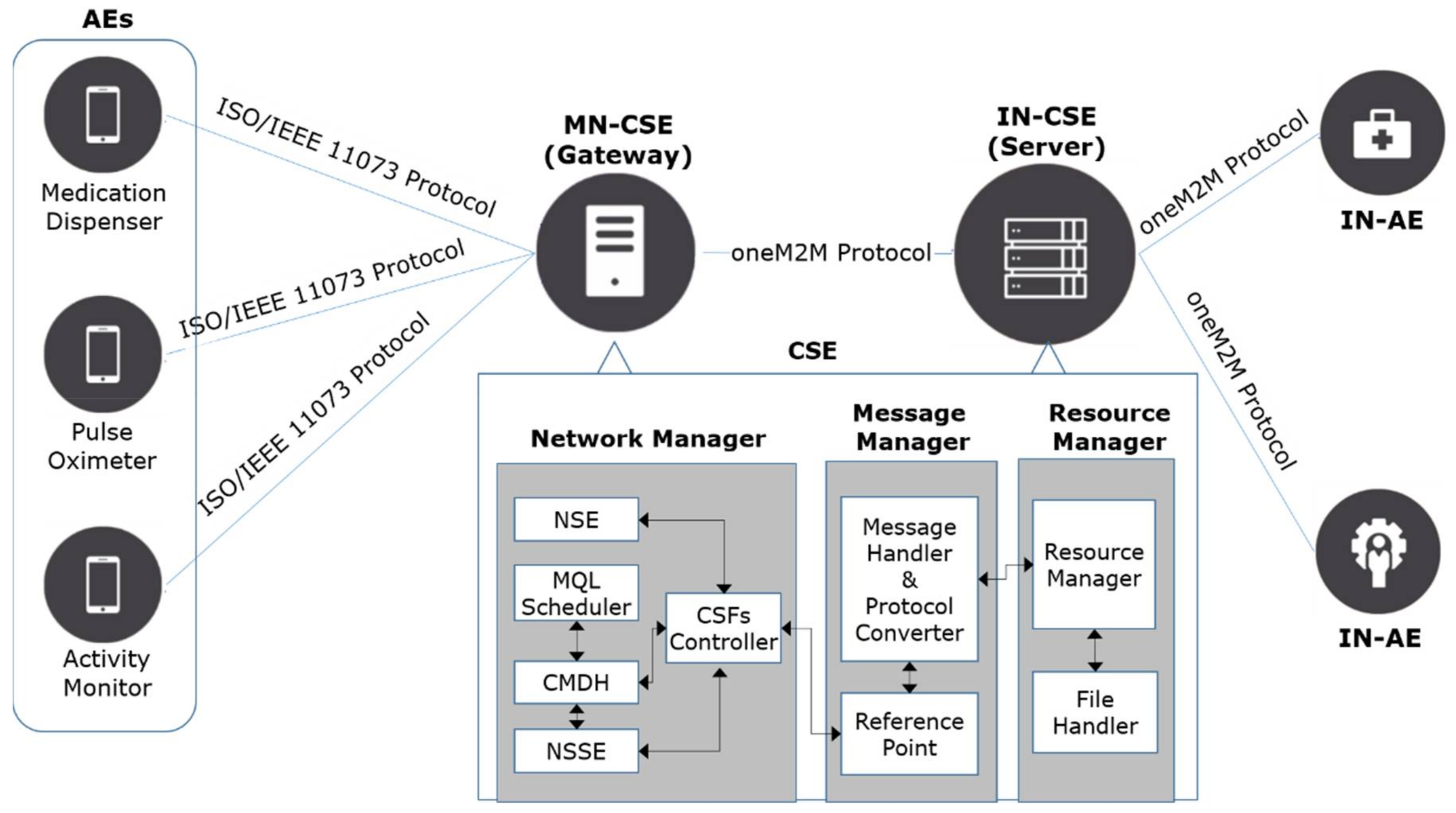
The dual plane architecture is applied to the single plane IoT system developed in our previous research [3,4]. For this reason, we will describe the single plane IoT system before introducing the dual plane architecture. The single plane IoT system conforms to the oneM2M (one Machine-to-Machine) protocol, which is an international communication protocol standard for IoT systems [5], and consists of four types of components: AE (Application Entities), MN-CSE (Middle Nodes-Common Service Entities), IN-CSE (Infrastructure Nodes-Common Service Entities) and IN-AE (Infrastructure Nodes-Application Entities). An AE is a program installed in IoT user devices, and its main purposes are to measure or sense its user’s data and to send them to the MN-CSE. An MN-CSE acts as a gateway for traffic control and/or protocol conversion and conducts communications between AEs and IN-CSE. An IN-CSE functions as a monitoring or management server in the IoT system and gathers AEs data through MN-CSEs. An IN-AE can access a user’s data by accessing the IN-CSE node via an IoT network.
Three types of PHDs (Personal Health Devices)—Medication dispenser [6], Pulse oximeter [7] and Activity monitor [8]—were used as AEs in our previous studies and are also used in this paper. These PHDs conform to the ISO/IEEE 11073 protocol, an international standard for PHDs [9].
The CSE (MN-CSE and IN-CSE), which is the main part of the IoT system, consists of a Network Manager, a Message Manager, and a Resource Manager. The Network Manager deals with communications between AEs and an IN-CSE. The Message Manager analyzes the incoming messages and converts the ISO/IEEE 11073 protocol messages into the oneM2M protocol and vice versa. The Resource Manager manages resource trees in which the information of every object the IoT system manages is stored. Figure 1 shows the previously proposed single plane IoT system and the internal structure of the CSE.
The communication procedures between AEs and the MN-CSE are divided into four phases: association, configuration, operation and disassociation phases [10]. During the association phase, PHDs and the MN-CSE establish a communication session using an AARQ (Association Request) and AARE (Association Response) messages. During the configuration phase, PHDs send their device configurations using a PRST (Presentation) message with an MDC_NOTI_CONFIG event type. In the operation phase, the measurement messages are transferred from the AEs to the MS-CSE using PRST messages with an MDC_NOTI_SCAN_REPORT event type. Finally, the disassociation phase is for disassociating a communication session between a PHD and the MN-CSE. In this phase, an RLRQ (Association Release Request) and RLRE (Association Release Response) message are exchanged.
The traditional network applications, as well as the CSE in the single plane IoT system, have some shortcomings from both a message processing perspective and an architectural perspective [11,12,13]. The shortcomings caused by using kernel network stack in a packet processing perspective are as follows:
- The CSE creates communication sockets using some system calls to receive and send messages. In this way, an incoming message is copied several times to the memory for the user-space network application (i.e., CSE), and the copy operations increase the overall system workloads.
- The CSE receives an incoming message after processing by the kernel network stack, the design of which is quite complex, making this a time-consuming step that causes performance degradation.
- The CSE receives notice on an incoming new message by a kernel’s interrupt mechanism. That is, an interrupt occurs whenever a new message arrives in the system, and frequent interrupts can be problematic for an IoT system, as it should provide continuous and real-time services.
From an architectural perspective, the previous CSE was designed based on the single plane architecture (which means that signaling messages and user-data messages are processed in one plane together) and this leads to the following disadvantages:
- In the single plane architecture, all kinds of messages are sequentially processed in one plane. Therefore, if the system is already processing a signaling message, user-data messages have to wait until the signaling message is completed. This is ineffective. Signaling messages typically require more resources and time than the user-data messages because the main purpose of the signaling messages is to change or track some sessions or configurations, whereas the main purpose of the user-data messages is to be forwarded. Therefore, the performance of user-data processing relies on the performance of signaling message processing, and consequently, the overall performance of the IoT system is inevitably decreased.
- To increase the system capacity such as the number of CPU cores, the capacity for the control part and the data part must be increased symmetrically. In addition, all of the systems deployed in the field should always contain two parts. In other words, an asymmetric increase of system capacity or physically distributed deployment for the data part only is impossible, as the two parts are not separated.
2.2. Packet Processing Solutions and Related Research
In this information age, the amount of data transferred over networks and the corresponding traffic workloads have been growing dramatically, and IoT environments are no exception. Despite the use of high speed NICs (Network Interface Cards) and the advancement of network applications, this issue still remains a problem, as the essential bottlenecks arise not in the user-space, but in the kernel-space. To solve this problem, various dedicated network hardware solutions have been proposed. The representative examples are EZChip’s NP-4 and NPS-400(Mellanox Technologies, Yorneam Illit, Israel) [14], Cavium’s OCTEON line (Cavium, San Jose, CA, USA) [15] and Tilera’s Tile-Gx line (Mellanox Technologies, Yorneam Illit, Israel) [16].
Aside from the hardware-based approaches, software-based fast packet processing solutions have been introduced as well, increasing the interest in SDN (Software-Defined Networking) and NFV (Network Function Virtualization). The main solutions are NTOP’s PF_RING (NTOP, Pisa, Italy) [17], Intel’s DPDK (Data Plane Development Kit) (Intel, Santa Clara, CA, USA) [18], and 6WIND’s 6WINDGate (6WIND, Montigny-le-Bretonneux, France) [19].
PF_RING is a high-speed packet capture, filtering, and analysis solution, and was proposed by NTOP to solve the interrupt and memory copy issues of the existing network stack. There are two versions of this solution: Vanilla PF_RING and PF_RING ZC. Vanilla PF_RING is free software and uses NAPI (New API) [20], an extension to the device driver packet processing framework, to avoid system interrupts. PF_RING ZC is a commercial version which supports the zero-copy concept. Both versions of PF_RING support x86-based processors and various Linux distributions and NICs.
Intel’s DPDK is an open-source solution for developing the data plane. It uses a zero-copy concept and PMD (Poll Mode Driver) to avoid the kernel’s interrupt mechanism. Thanks to these features, a packet received in the NIC can be referenced to the user application directly, without the kernel’s interference. In addition, it offers several cipher algorithms such as AES-CBC, AES-CTR, AES-GCM and HMAC-SHA1, and some lookup algorithms such as hash and longest prefix match. It is designed to run on Intel x86-based, IBM Power PC and ARM processors, and supports various Linux distributions and NICs.
6WIND’s 6WINDGate is a commercial solution and works on various platforms such as ARM, Cavium, Intel and Mellanox. It also uses a zero-copy concept and supports various cipher algorithms. It supports data plane and control plane architectures and provides a synchronization module to synchronize both planes. Like the other solutions, it supports x86-based PC processors and various Linux distributions and NICs.
Table 1 summarizes the features of the packet processing solutions. All of the solutions listed in Table 1 can work in the cloud environment, and support x86-based PC processors and various Linux distributions and NICs. However, while Vanilla PF_RING can bypass the kernel’s interrupt mechanism by using NAPI polling, it still remains in overhead, requiring memory copy operations to copy received packets into a user space buffer due to the absence of the zero-copy concept. On the other hand, PF_RING ZC applies the zero-copy concept to bypass the kernel’s network stack. However, this makes it difficult to add or modify some functions, since it is a commercial solution. 6WINDGate supports all of the features of DPDK, and provides processing functions to handle IKE (Internet key exchange) and TCP messages. However, a drawback of 6WINDGate is that it is a commercial solution. In addition, its update schedule may be slow compared with DPDK, since it works based on DPDK; that is, it can only be updated after applying DPDK’s updates to its base library when a new version of DPDK is released.
On the other hand, it has been found that DPDK is a suitable solution to apply to IoT environments as it is open source, works in the cloud environment and supports x86-based PC processors and various Linux distributions and general NICs. But there are several drawbacks associated with the development of a DPDK-enabled network system. When DPDK is used, the NIC is no longer recognized by the Linux kernel. In other words, a DPDK-enabled network system cannot benefit from various network processing functions that have already been implemented in the kernel’s network stack [21].
The proposed architecture is basically the same as the SDN, and network slicing technologies that enable flexible network control by separating the two planes have been proposed in several advanced studies and applications. For example, Zhou et al. [22] proposed a multicore fast Ethernet switch based on DPDK, and Pongracz et al. [23] proposed an SDN architecture in an LTE environment. Nguyen et al. [24] applied the DPDK to an OpenFlow software switch. These previous studies applied SDN and DPDK in order to improve packet forwarding performance and provide flexibility, but their application was limited to the general Ethernet switch. On the other hand, several efforts have been made to employ SDN techniques in IoT environments. Yiakoumis et al. [25] described a prototype for slicing home networks in an IoT environment. It slices a physical network into multiple layers to isolate the traffic and bandwidth between providers. Qin et al. [26] proposed an SDN controller and roles for the controller such as resource matching and flow scheduling. In addition to these papers, there have been a number of studies on using an SDN controller for the efficient orchestration of network resources [27,28,29]. Although these studies provide valuable SDN architectures for IoT environments and efficient methods for developing and deploying an SDN controller, there has been little work done on building a high-performance data plane and application in the healthcare domain.
From a data scale perspective, when a large number of things generate huge messages, the area of big data faces similar challenges as the area of IoT. In this area, many researchers are attempting to address the problem of handling this large amount of data [30]. Basanta-Val et al. [31] proposed a big data architecture which focused on analyzing time-critical data using clusters of machines and extended online and offline analytic tools. Memos et al. [32] proposed a compression algorithm for a surveillance system in IoT. This approach aims to enable the rapid transmission of captured media data from the sensors to user’s surveillance system. To achieve this, it employs a video compression format. While it is obvious that methods for improving analysis of performance and for compressing data to be sent would be valuable in terms of guaranteeing system scalability, our approach is focused on addressing the scalability problem by improving the I/O performance of each single network node.
The aims of this paper are (1) to separate the control plane and the data plane, (2) to apply DPDK to the data plane in order to improve message forwarding performance, (3) to cast complex and time-intensive jobs for processing signaling messages on the control plane, (4) to provide a method for synchronization between the two planes, and (5) to present a practical application of IoT in the healthcare domain.
3. Design and Implementation Results
3.1. System Overview
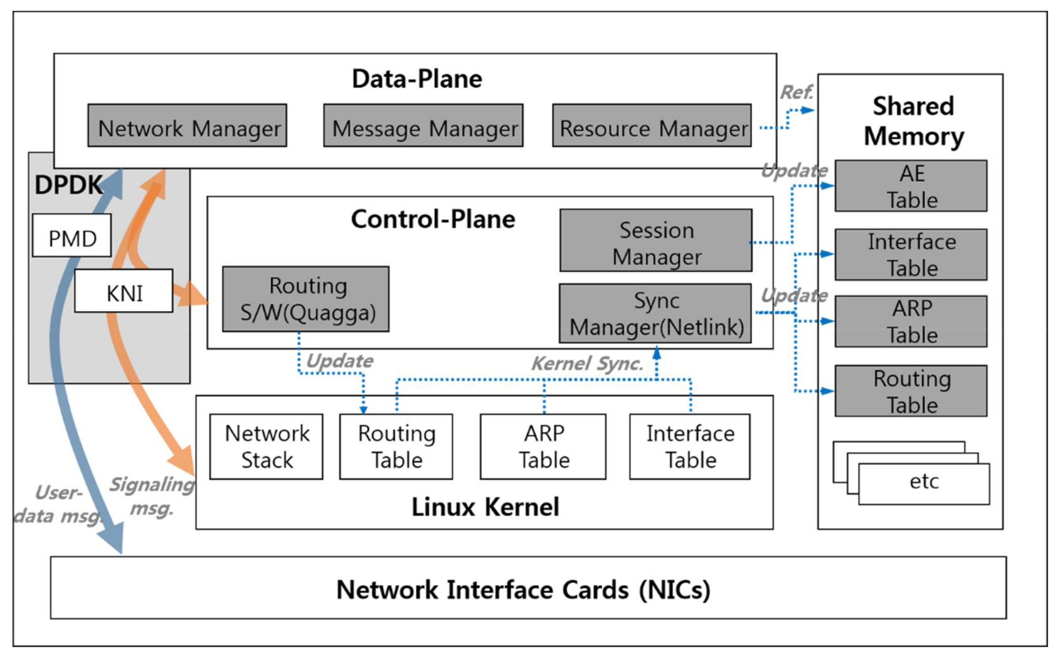
To overcome the problems of the single plane architecture mentioned in Section 2.1, we propose an approach of separating out the control part from the CSE, which is called a dual plane architecture. Figure 2 depicts the architecture of the CSE under the dual plane architecture. The CSE is comprised of a data plane, a control plane, and shared memory. The data plane is designed to be devoted to user-data message processing, and the control plane is in charge of processing complex and time-intensive signaling messages. The shared memory acts as a mediator between the two planes.
The data plane includes the following components:
- Network Manager receives and sends messages to/from AEs and IN-CSE. It also passes signaling messages to the control plane.
- Message Manager performs the same role as in the previously proposed system: message analysis and protocol conversion. In this paper, it has the additional role of distinguishing between a user-data message and a signaling message. If an incoming message is a user-data message, it processes the message and then forwards the message to the IN-CSE; if not, it throws the message to the control plane and processes next incoming message immediately.
- Resource Manager manages resource trees in which the information and measurements of every AE the IoT system manages is stored. It also refers to the forwarding-related information such as the Interface Table, ARP Table and Routing Table to forward a user-data message to the IN-CSE or AEs.
The control plane consists of the following components:
- Session Manager processes AE-related signaling messages and updates the AE session information and configurations which are supposed to be stored as an entry of the AE Table in the Shared Memory.
- Sync Manager monitors forwarding-related information which is represented as the forwarding-related signaling message and maintained by the Linux Kernel. When a change in forwarding-related information is detected, the Sync Manager updates the change in the Shared Memory.
- Routing software, which runs on the Linux OS, analyzes routing messages received from the neighbor routers, and updates the kernel’s routing table. The updated routing table is synchronized with the Shared Memory by the Sync Manager.
The Shared Memory contains the following tables:
- AE Table contains session information such as AE device ID, IP address, and session status, and device configurations such as types of transmitting measurements.
- Interface Table includes the information of network interfaces such as IP address, MAC address, interface status, and so on.
- ARP Table is a mapping table between the next hop’s IP address and MAC address.
- Routing Table contains the next hop’s IP address and output interface index for message forwarding.
We divided incoming messages into two categories: user-data messages and signaling messages. The signaling messages were further divided into two types: AE-related and Forwarding-related signaling messages, as listed in Table 2.
3.2. Data Plane
The data plane is designed and implemented based on Intel DPDK [18] to improve message processing performance. The data plane uses zero-copy and PMD concepts provided by DPDK. Zero-copy reduces the operational overhead generated by multiple copies of incoming messages, and the PMD allows the data plane to access the incoming messages directly by bypassing the complex and time-consuming kernel network stack and interrupts.
The distinctive feature of the dual plane architecture compared to the previous single plane architecture is that the former processes signaling and user-data messages separately and simultaneously in the different planes, whereas the latter handles both kinds of messages in one plane sequentially. In the dual plane architecture, if an incoming message is an AE-related or Forwarding-related signaling message (i.e., exception from the data plane perspective), the data plane does not continue processing it, but throws it to the control plane instead, and processes the next incoming message immediately. This enables the data plane to be dedicated to message forwarding, and as a result, achieves high performance in message forwarding. In the data plane, an incoming message goes through four phases: receiving, processing, exception handling, and forwarding.
During the receiving phase, the Network Manager periodically monitors its RX ring buffer, which contains packet descriptors (pointers) about incoming messages. If the buffer contains a newly added packet descriptor, then the Network Manager acquires the message using the pointer in the packet descriptor and passes it to the Message Manager.
In the processing phase, the Message Manager analyzes the message type and the event type of the received message. It processes only the PHD’s measurements included in a PRST message with the MDC_NOTO_SCAN_REPORT event type, and throws the remaining messages to the control plane. In this paper, pulse rates and SpO2 from the pulse oximeters, medication status from the medication dispensers, and distance, activity time, intensity and steps from the activity monitors are the user-data messages that are to be processed in the data plane. It also verifies that the incoming message is from the associated AE by referring to the AE Table in the Shared Memory. If it is not, it considers the message as coming from a disassociated PHD, and discards the message. In addition, the Message Manager converts the received ISO/IEEE 11073 message [10] to the oneM2M protocol message [5] before forwarding it as presented in our previous research [3,4].
If the incoming message is determined by the Message Manager to be a signaling message, it enters the exception handling phase. In this phase, a signaling message is queued in an RX FIFO queue for the KNI (Kernel NIC Interface) [33] thread and is sent to the kernel network stack. The details of the KNI procedure are explained in Section 3.4.
During the forwarding phase, the data plane refers to three tables: Interface, ARP and Routing Table. The Resource Manager looks up the Routing Table using the predefined server IP address as a key and acquires the next hop’s IP address and an output interface index as the results. Next, it refers to an interface entry in the Interface Table using the output interface index, and then extracts an IP address and MAC address, which are used as a source MAC address and a source IP address in the Ethernet and IP header, respectively. After that, it looks up the ARP Table using the server IP address to determine a destination MAC address. Finally, the Message Manager rebuilds the Ethernet and IP header of the forwarding message based on the lookup results and forwards it to the IN-CSE through the DPDK PMD. A Longest prefix match lookup, a direct lookup and a hash lookup are used for searching the Routing, Interface and ARP tables, respectively.
The key things here are that (1) the data plane refers the forwarding-related information from the Shared Memory, not from the kernel space, and (2) the data plane forwards itself without the help of the kernel network stack.
3.3. Control Plane
The main purposes of the control plane are (1) processing signaling messages received from the data plane, (2) storing the AE-related information to the Shared Memory, and (3) synchronizing Forwarding-related information from the kernel to the Shared Memory. The signaling messages are divided into two types of messages: AE-related signaling messages and forwarding-related signaling messages, as listed in Table 2. The former type of messages are handled and stored in the AE Table in the Shared Memory by the Session Manager, and the latter type of messages are processed by the network software or daemons running on the Linux OS (i.e., controlled by the kernel network stack), updated to the Linux kernel tables, and finally stored to several tables such as the Interface Table, ARP Table and Routing Table in the Shared Manager by the Sync Manager.
The two managers use different updating methods: direct and indirect. The Session Manager directly analyzes a message received from the data plane and extracts the message type and the event type. It processes only the AARQ, AARE, RLRQ, RLRE, and PRST message with the MDC_NOTI_CONFIG event type, and discards the remaining messages. In this paper, the Session Manager updates the PHD session information such as device ID, device type, and session association time to the AE Table to track the communication session between a PHD and a server. It also updates configurations of PHD such as attribute IDs to the AE Table.
The Sync Manager monitors the changes of Linux kernel tables instead of directly analyzing signaling messages. If the Sync notices a change in Linux kernel tables, then it updates the change to the Shared Memory. This method is efficient in terms of scalability and maintainability, since it is not necessary to modify the native kernel-based software such as Quagga [34] or kernel network stack.
3.4. Interoperation between Two Planes
Since the proposed dual plane architecture separates the data plane and the control plane, interworking between the two planes is required. In other words, signaling messages among messages received in the data plane have to be passed to the control plane, and the information acquired in the control plane should be referred by the data plane.
To achieve this, we apply three interworking methods. First, the KNI of DPDK is used for exchanging messages between the two planes. Since the interfaces under the DPDK are only used in the data plane and are not assigned to the control plane, the control plane is not aware of the existence of the interfaces. As a result, it is not possible to pass signaling messages from the data plane to the control plane. For this reason, the DPDK proposed the KNI concept [33]. KNI assigns virtual interfaces in the control plane corresponding to data plane interfaces, and allows two planes to exchange messages each other. Second, we generate hugepage shared memory to allow data planes to refer the forwarding-related information. The control plane updates several tables in the Shared Memory, and the data plane uses the updated tables. Finally, we use Netlink [35]. Netlink is a Linux kernel interface for IPCs (Inter-Process Communication) between the kernel and a user-space application. Through Netlink, a user-space application can monitor changes of the kernel’s information [36]. In the dual plane architecture, a change in the kernel’s information should be referred to the forwarding decision in the data plane. The Sync Manager is made aware of the changes by Netlink and stores the changes in the Shared Memory.
These interoperation methods are effective for performance tuning (i.e., assigning multiple cores to the data plane and one CPU cores to the control plane) because the control plane is independent of the data plane. In addition, these methods allow a physically distributed system which consists of one physical server including only a control plane and several physical servers including only a data plane.
3.5. Implementation Environments
On the basis of the proposed architecture, the dual plane IoT system is constructed in this paper. The proposed architecture is applied to the MN-CSE. The hardware and software specifications are listed in Table 3.
Since the proposed system is designed and implemented based on the Intel DPDK, it has a similar hardware dependency to the DPDK. The DPDK is designed to run on Intel x86-based, IBM Power PC and ARM processors and a wide range of NICs by multiple vendors such as Intel (Santa Clara, CA, USA), Emulex (Costa Mesa, CA, USA), Mellanox (Yorneam Illit, Israel), and Cisco (San Jose, CA, USA). That is, the proposed system is designed to run on commodity hardware instead of highly specialized hardware, and is independent of any hardware type. For generality and ease of maintenance, the proposed system is implemented in C language under a Linux CentOS in an x86 machine, and uses Intel CPU and common NIC, Intel I217-V (Intel, Santa Clara, CA, USA).
On the other hand, the proposed system requires huge pages with more than 2 GB of memory for the large memory pool allocation used for packet buffers. Furthermore, in the proposed dual plane architecture, a CPU core (or thread) assigned to the data plane dedicates its CPU resource to busy-wait polling to avoid NIC interrupts and system calls. For this reason, an additional CPU core for the control plane is needed to handle control messages. However, these hardware requirements are acceptable for recent general computers. For high scalability, it is running under the VMware hypervisor (VMware, Palo Alto, CA, USA) so that the deployment or cloning of the system is easy.
4. Performance Experiments
4.1. Proposed System Overhead
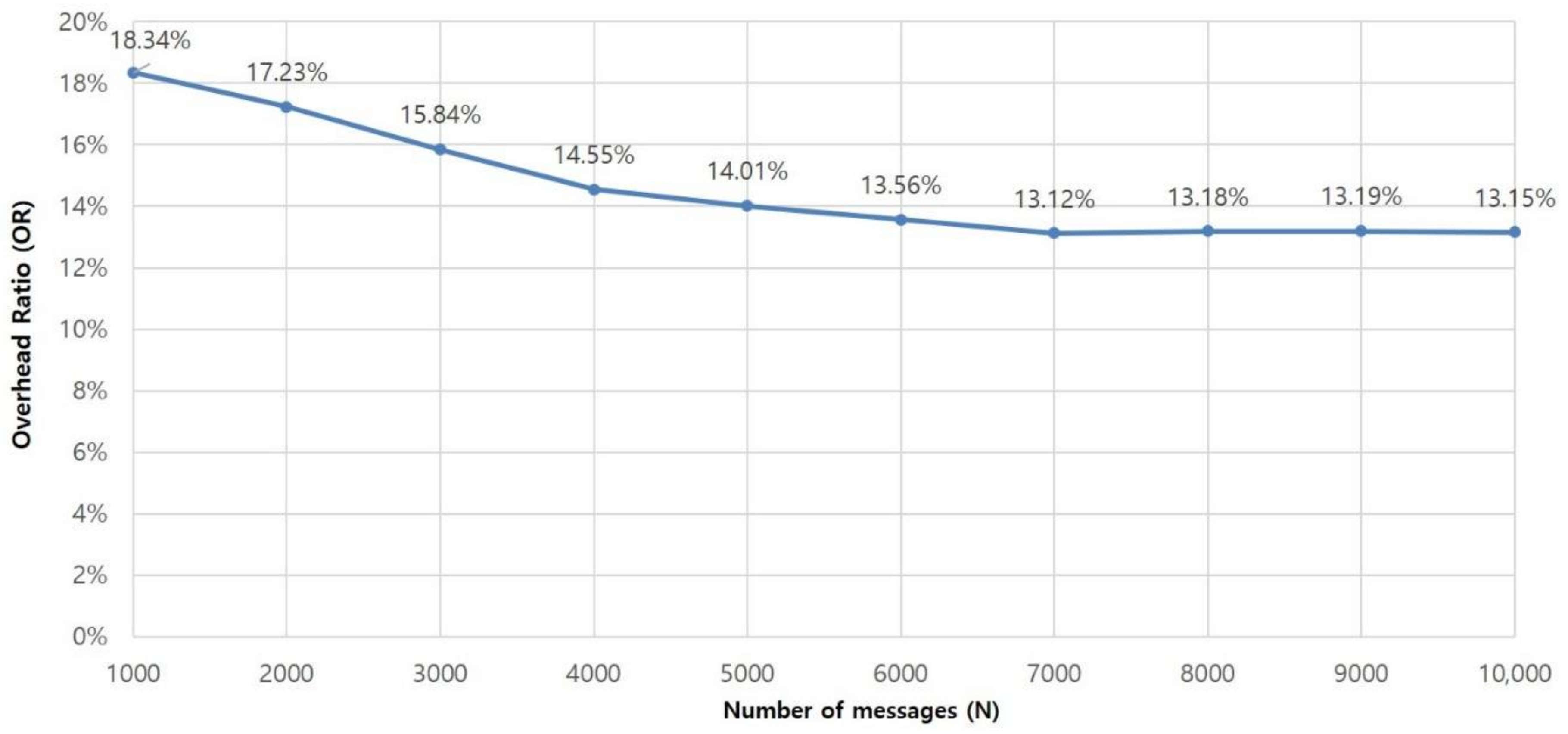
To prove the effectiveness of the proposed architecture, we conducted an experiment to calculate the proportion of overhead in the system throughput in terms of time. This proportion shows the extent to which the proposed architecture influences system performance. In this paper, the overhead indicates the total time from receiving to forwarding a particular message excluding message processing time such as parsing, analyzing, and converting. Therefore, the overhead for N messages, denoted by O(N), can be represented as follows:
where tT denotes total time and tP denotes message processing time. Then the overhead ratio, OR, can be simply calculated by
The overhead ratio was measured and calculated repeatedly, while increasing the number of the messages, N, from 1000 to 10,000. The result of the evaluation is described in Figure 3. In the experiment, the overhead ratio decreased and stayed stable at about 13.1 percent as N increased. This proves that the overhead of the proposed architecture has a modest effect on overall performance and is robust to heavy traffic.
4.2. Throughput and Message Loss Ratio
To validate the performance of the dual plane architecture, we compared the performance of the proposed system with that of the single plane IoT system developed in our previous research, which processes both user-data and signaling messages in one plane and does not apply the DPDK. For this test, two comparison systems were run on the same hardware condition listed in Table 3. The test messages used in the experiments are user-data messages sent from three types of PHDs to the MN-CSE. For the test, we use PHD simulators to generate large amounts of messages. Each simulator sends its measurements and the MN-CSE forwards the messages to the IN-CSE.
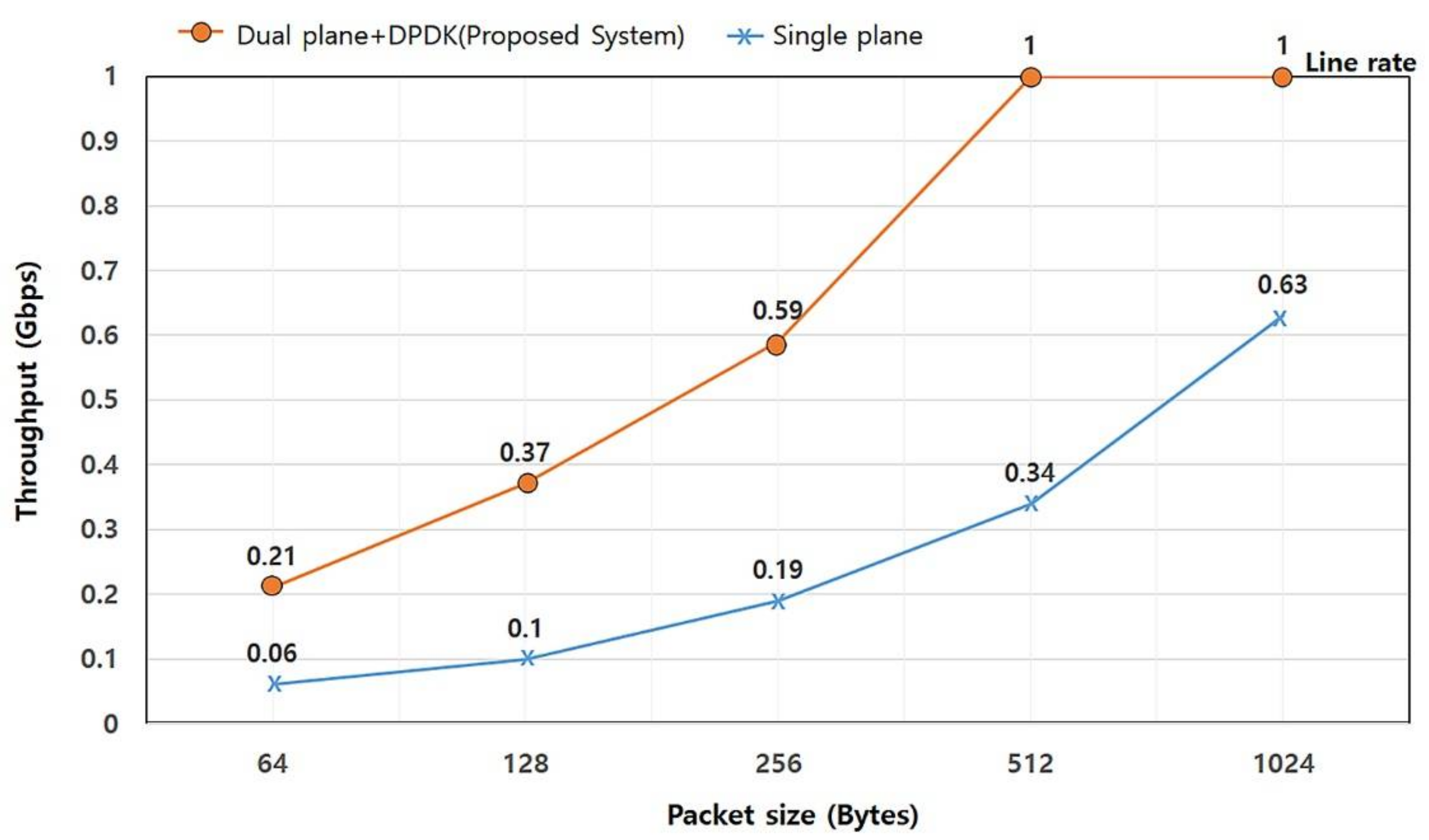
First, we conducted a throughput test which indicates the fastest forwarding rate without packet loss at a line speed of 1 Gbps. The throughput was measured repeatedly, while increasing the size of the messages. The result of the evaluation is described in Figure 4. According to Figure 4, the dual plane IoT system outperforms the single plane IoT system considerably, by as much as 250%, 270%, 210%, 190% and 58% for each message size. This result shows that the dual plane architecture proposed in this paper can forward user-data messages at a line speed with messages of 512 bytes or more while the single plane IoT system shows a 34% line rate. Furthermore, it shows much better performance than the single plane IoT system with small size messages. As the benchmark result shows, it is obvious that the proposed architecture is more suited to an IoT environment, in which small messages have to be exchanged very frequently.
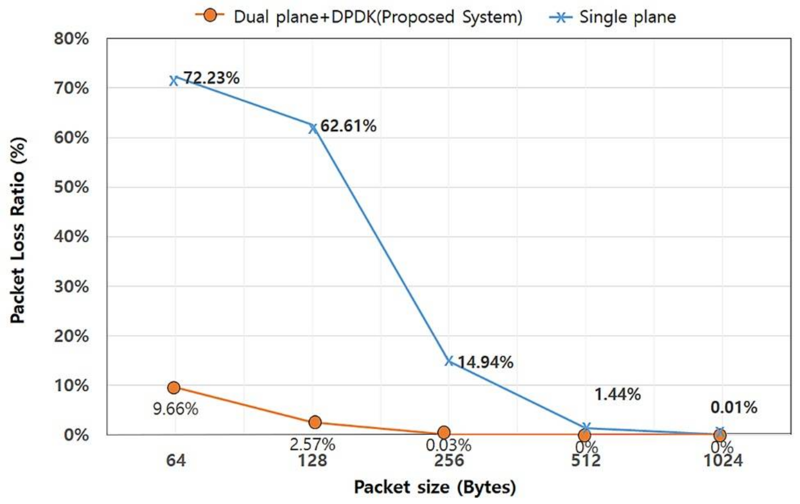
Next, we measured the message loss rates of each system at a line speed of 1 Gbps while increasing the size of the messages. In a typical network system, NIC line rate represents theoretical performance; actual NIC performance is lower than the theoretical performance due to message processing and packet IO overheads. Therefore, a certain number of messages should be delayed in the receiving queue. A system or gateway that receives messages at too high a rate may experience a full queue. Since the number of newly incoming messages is larger than amount of processed and sent messages, the number of messages delayed in the receiving queue (waiting to be processed and forwarded) will continuously increase. Because a network system has finite buffer memory to hold the queue and cannot expand the buffer memory indefinitely, queue congestion occurs, and the queue becomes full as a result [37]. In this case, the system has no other option than to simply discard excess packets (i.e., packet loss).
Therefore, comparison of the packet loss rate provides us with information regarding which architecture is more suitable for a network node. The results of the evaluation are shown in Figure 5. As the result of the evaluation shows, message loss occurs in both single and dual architectures. However, the amount of message loss in the dual plane system is much less than in the single plane system, since the dual plane system can handle data messages much faster than the single plane system. The loss rate of the single plane IoT system with a 64-byte message is 72.23%, while that of dual plane is only 9.66%. In addition, a dual plane IoT system does not drop any received messages 512 bytes or more, while the single plane IoT system still drops some of the received messages. This result is due to the high IO performance of DPDK, and the independent message processing approach of the dual plane architecture.
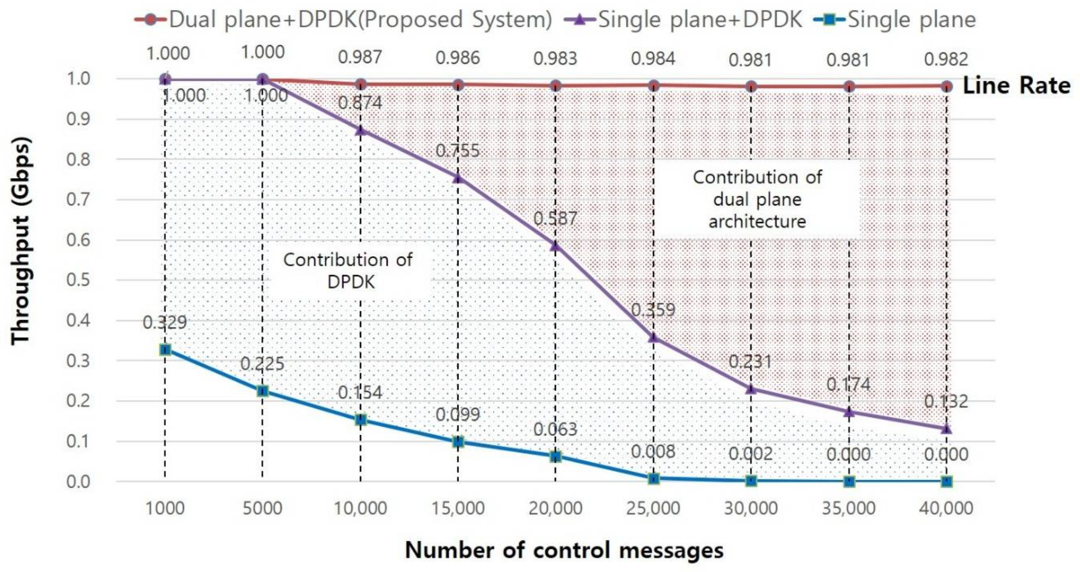
Finally, we compared the throughput performance of two different single plane IoT systems: a single plane IoT system without and with DPDK. The former receives and sends messages through the kernel network stack instead of using DPDK, and the latter bypasses the kernel network stack using DPDK. In the test, the throughput was measured with a fixed packet size of 512 bytes, while increasing the number of control messages from 1000 to 40,000. For example, if the number of incoming control messages is 10,000, the number of user data messages becomes 252,144 (because the maximum PPS is 262,144 for a packet size of 512 bytes). The control messages in this test consist of Association Request messages and Configuration Request messages, as shown in Table 2. If the system receives those control messages, it should verify the validity of the establishing session, update session information to its session table, establish a session with a user device and a server and configure device parameters to its session table.
The result of the evaluation is described in Figure 6. As shown in the Figure, the performance of the dual plane IoT system is almost the same regardless of the number of control messages, and only a 1.9% performance loss occurs. This number represents the overhead for packet relay between the data and control plane in the dual plane architecture. In contrast, the performance of the single plane architecture with DPDK drops sharply when the number of control messages exceeds 10,000, while that of the single plane architecture without DPDK approaches 0. The throughput of the single plane architecture with DPDK only shows nearly 89%, 77%, 60%, 36%, 24%, 18% and 13% of the throughput of the dual plane architecture with DPDK (while the number of control messages are increased from 10,000 to 40,000), even though both systems use the same amount of memory and the same number of cores. No matter how quickly the DPDK polls received packets, packet delay and queue congestion in the handling of time-consuming control message are unavoidable, leading to a performance degradation. These performance differences represent the contribution of the dual plane architecture. That is, the dual plane architecture can improve system performance and is more efficient than the single plane architecture, particularly in an environment where control messages are generated frequently.
Second, the comparison of a single plane architecture with and without DPDK found that DPDK can relieve performance degradation. When there are few control messages, the performance of the single plane architecture with DPDK is much different than the performance of the single plane architecture without DPDK. We can verify that although the DPDK can increase the system throughput and can relieve performance degradation by improving packet IO performance, it still suffers from handling time-consuming control messages, which consequently leads to a performance degradation problem.
4.3. Experiment Analysis
As our experiments have shown, the proposed dual plane IoT system provides better performance than that of the previous single plane IoT system. The reason for the high performance of the proposed system can be explained in terms of packet IO performance and packet processing architecture. The DPDK solution applied in our system uses a polling mechanism to avoid time-consuming interrupts and system calls. This reduces the delay time of incoming packets stored in a receiving queue, and prevents packet losses caused by a full receiving queue. According to the comparison tests, the DPDK can improve system throughput by more than 200%. From an architectural point of view, the proposed dual plane architecture contains two planes and handles different types of messages in different planes. This helps to improve system performance by having data messages forwarded continuously, regardless of whether control messages are being processed. As shown in Figure 6, the dual plane architecture outperforms the single plane architecture even though both use the same DPDK solution, and the gap between the performance of the two systems becomes wider as the number of control messages is increased. As a result of these performance advantages, the proposed system shows a lower message loss ratio.
To sum up, the proposed system can improve the network performance and shows high performance when receiving packets of a small size and a large number of control messages. This feature makes our system highly suitable for IoT environments, which usually involve the regular transmission of small-sized messages and frequent device attach and detach events.
5. Conclusions
In this paper, we proposed a dual plane architecture for a high performance IoT system. The proposed architecture consists of a control plane and a data plane. The control plane processes signaling messages and the data plane processes and forwards user-data messages. In the architecture, the data plane accesses the incoming messages directly by bypassing the complex and time-consuming kernel network stack and interrupts. In addition, it does not process signaling messages, and sends them to be processed in the control plane. This allows the data plane to be dedicated to message forwarding. In contrast, the control plane analyzes signaling messages and provides controlling information to the data plane. This allows the system to process messages separately and simultaneously in the different planes and consequently helps to improve overall performance. To verify the proposed architecture, we applied the architecture to our previous single plane IoT system which consists of three types of IoT devices, an MN-CSE and an IN-CSE. In addition, we conducted performance comparison tests with the previous single plane IoT system. The results indicate that the performance of the proposed architecture is much higher than that of the single plane architecture, for all message sizes. In addition, it proves that the proposed architecture shows outstanding processing performance for small-sized messages. This means that the proposed architecture is highly appropriate for IoT environments.
In future research, we plan to apply the proposed system to various IoT environments, such as the smart city and smart utility areas. The scalability issue is also a major consideration in those areas, and we expect that the proposed dual architecture system can contribute to improving system scalability in those fields. In addition, we plan to study the distributed dual plane architecture for IoT environments. In the architecture, there are several distributed data planes and one central control plane which manages all other data planes.
Acknowledgments
This research was supported by the Basic Science Research Programs through the National Research Foundation of Korea (NRF), funded by the Ministry of Education, Science and Technology (No. NRF-2015R1D1A3A03019278).
Author Contributions
KeeHyun Park conceived the ideas proposed in this paper and designed the dual plane architecture; JuGeon Pak implemented the proposed architecture based on the Intel DPDK and performed the related experiments; KeeHyun Park and JuGeon Pak analyzed the data and wrote the paper.
Conflicts of Interest
The authors declare no conflict of interest.
References
- Zanella, A.; Bui, N.; Castellani, A.; Vangelista, L.; Zorzi, M. Internet of Things for Smart Cities. IEEE Internet Things J. 2014, 1, 22–32. [Google Scholar] [CrossRef]
- Yaqoob, I.; Ahmed, E.; Hashem, I.A.T.; Ahmed, A.I.A.; Gani, A.; Imarn, M.; Guizani, M. Internet of Things Architecture: Recent Advances, Taxonomy, Requirements, and Open Challenges. IEEE Wirel. Commun. 2017, 24, 10–16. [Google Scholar] [CrossRef]
- Park, K.H.; Park, J.S.; Lee, J.W. An IoT System for Remote Monitoring of Patients at Home. Appl. Sci. 2017, 7, 260. [Google Scholar] [CrossRef]
- Woo, M.W.; Lee, J.W.; Park, K.H. A Reliable IoT system for Personal Healthcare Device. Future Gener. Comput. Syst. 2017, 78, 626–640. [Google Scholar] [CrossRef]
- oneM2M Standard. Available online: http://www.onem2m.org/ (accessed on 20 October 2017).
- Pak, J.G.; Park, K.H. UbiMMS: An ubiquitous medication monitoring system based on remote device management methods. Health Inf. Manag. J. 2012, 41, 26–30. [Google Scholar] [CrossRef]
- Pak., J.G.; Park, K.H. Pulse oximeter monitor for u-health service. In Proceedings of the International Conference on Computer and Applications, Seoul, Korea, 30–31 March 2012; p. 61. [Google Scholar]
- Pak, J.G.; Park, K.H. A smart personal activity monitoring system based on wireless device management methods. In Communications in Computer and Information Science; Park, J., Yang, L., Lee, C., Eds.; Springer: Berlin, Heidelberg, 2011; Volume 184, pp. 335–342. ISBN 978-3-642-22332-7. [Google Scholar]
- IEEE 11073 for Personal Health Device Standard. Available online: http://www.11073.org (accessed on 20 October 2017).
- IEEE 11073 for Personal Health Device Communication Protocol, ISO/IEEE 11073-20601. Available online: http://www.11073.org (accessed on 20 November 2017).
- Brouer, J.D. Network stack challenges at increasing speeds. In Proceedings of the Linux Conference, Auckland, New Zealand, 12–16 January 2015. [Google Scholar]
- Salim, J.H. When NAPI comes to town. In Proceedings of the Linux Conference, Swansea, UK, 4–7 August 2005. [Google Scholar]
- Fusco, F.; Luca, D. High Speed Network Traffic Analysis with Commodity Multi-core Systems. In Proceedings of the 10th ACM SIGCOMM Conference on Internet Measurement, Melbourne, Australia, 1–3 November 2010; pp. 218–224. [Google Scholar]
- EZChip NP. Available online: http://www.mellanox.com/page/npu_overview?mtag=npu_overview (accessed on 20 October 2017).
- Cavium OCTEON. Available online: http://www.cavium.com/OCTEON_MIPS64.html (accessed on 20 October 2017).
- Tilera Tile-GX. Available online: http://www.mellanox.com/page/multi_core_overview (accessed on 20 October 2017).
- NTOP PF RING. Available online: http://www.ntop.org/products/packet-capture/pf_ring (accessed on 20 October 2017).
- Intel DPDK. Available online: http://dpdk.org (accessed on 20 October 2017).
- 6WID 6WINDGate. Available online: http://www.6wind.com/products/6windgate (accessed on 20 October 2017).
- NAPI. Available online: https://wiki.linuxfoundation.org/networking/napi (accessed on 20 October 2017).
- Kourtis, M.A.; Xilouris, G.; Riccobene, V.; McGrath, M.J.; Petralia, G.; Koumaras, H.; Gardikis, G.; Liberal, F. Enhancing VNF performance by exploiting SR-IOV and DPDK packet processing acceleration. In Proceedings of the 2015 IEEE Conference on Network Function Virtualization and Software Defined Network, San Francisco, CA, USA, 18–21 November 2015. [Google Scholar]
- Zhou, D.; Fan, B.; Lim, H.T.; Kaminsky, M.; Andersen, D.G. Scalable, high performance ethernet forwarding with CuckooSwitch. In Proceedings of the 9th ACM conference on Emerging Networking Experiments and Technologies, Santa Barbara, CA, USA, 9–12 December 2013; pp. 215–220. [Google Scholar]
- Pongracz, G.; Molnar, L.; Kis, Z.L. Removing Roadblocks from SDN: OpenFlow Software Switch Performance on Intel DPDK. In Proceedings of the 2013 Second European Workshop on Software Defined Networks, Berlin, Germany, 10–11 October 2013. [Google Scholar]
- Nguyen, V.G.; Kim, Y.H. Slicing the next mobile packet core network. In Proceedings of the 2014 11th International Symposium on Wireless Communications Systems, Barcelona, Spain, 26–29 August 2014; pp. 901–904. [Google Scholar]
- Yiakoumis, Y.; Yap, K.K.; Katti, S.; Parulkar, G.; McKeown, N. Slicing home networks. In Proceedings of the 2nd ACM SIGCOMM Workshop on Home Networks, Toronto, ON, Canada, 15 August 2011; pp. 1–6. [Google Scholar]
- Qin, Z.; Denker, G.; Giannelli, C.; Bellavista, P.; Venkatasubramanian, N. A software defined networking architecture for the internet-of-things. In Proceedings of the 2014 IEEE Network Operations and Management Symposium, Krakow, Poland, 5–9 May 2014. [Google Scholar]
- Caraguay, A.L.V.; Peral, A.B.; Lopez, L.I.B.; Villalba, L.J.G. SDN: Evolution and Opportunities in the Development IoT Applications. Int. J. Distrib. Sens. Netw. 2014, 10, 735142. [Google Scholar] [CrossRef]
- Nakao, A. Software-Defined Data Plane Enhancing SDN and NFV. IEICE Trans. Commun. 2015, 98, 12–19. [Google Scholar] [CrossRef]
- Kalkan, K.; Zeadally, S. Securing Internet of Things (IoT) with Software Defined Networking (SDN). IEEE Commun. Mag. 2017. [Google Scholar] [CrossRef]
- Lv, Z.; Song, H. Next-Generation Big Data Analytics: State of the Art, Challenges, and Future Research Topics. IEEE Trans. Ind. Inform. 2017, 13, 1891–1899. [Google Scholar] [CrossRef]
- Basanta-Val, P.; Audsley, N.C.; Wellings, A.J.; Gray, I.; Fernandez-Garcia, N. Architecting Time-Critical Big-Data Systems. IEEE Trans. Big Data 2016, 2, 310–324. [Google Scholar] [CrossRef]
- Memos, V.A.; Psannis, K.E.; Ishibashi, Y.; Kim, B.G.; Gupta, B.B. An Efficient Algorithm for Media-based Surveillance System (EAMSuS) in IoT Smart City Framework. Future Gener. Comput. Syst. 2017. [Google Scholar] [CrossRef]
- Yigit, F. Interworking with the Linux Kernel, Intel Shannon, DPDK Summit Userspace. 2016. Available online: https://dpdksummit.com/Archive/pdf/2016Userspace/Day02-Session06-FerruhYigit-Userspace2016.pdf (accessed on 20 October 2017).
- Quagga Routing Suite. Available online: http://www.nongnu.org/quagga (accessed on 20 October 2017).
- Netlink Protocol Library Suite. Available online: https://www.infradead.org/~tgr/libnl (accessed on 20 October 2017).
- He, KK. Kernel korner: Why and how to use netlink socket. Linux J. 2005, 2005, 11. [Google Scholar]
- Fiems, D.; Vuyst, S.D.; Wittevrongel, S.; Bruneel, H. Packet loss characteristics for M/G/1/N queueing systems. Ann. Oper. Res. 2006, 170, 113–131. [Google Scholar] [CrossRef]
Figure 1.
Structure of the Internet of Things (IoT) system and the Common Service Entities (CSE).

Figure 2.
CSE architecture for dual plane IoT system.

Figure 3.
Overhead ratio.

Figure 4.
Comparison of throughputs.

Figure 5.
Comparison of packet loss rates.

Figure 6.
Comparison of throughputs.


Table 1.
Features of the packet processing solutions.
| Features | Vanilla PF_RING | PF_RING ZC | DPDK | 6WINDGate |
|---|---|---|---|---|
| Software base | O | O | O | O |
| Open source | O | X | O | X |
| Universality | O | O | O | O |
| Cloud | O | O | O | O |
| Bypass Network Stack | △ | O | O | O |
| Security | X | X | O | O |
Table 2.
Categorized messages.
| Category | Message | Message Type | Event Type | Content |
|---|---|---|---|---|
| User-data | Data Report | PRST | MDC_NOTI_SCAN_REPORT | Invoke-id, Measurements (pulse rate, SpO2 …) |
| Data Response | PRST | MDC_NOTI_SCAN_REPORT | Invoke-id | |
| Signaling (AE-related) | Association Request | AARQ | - | Device ID, Device Type, Config-ID |
| Association Response | AARE | - | Device ID, Device Type, Result | |
| Disassociation Request | RLRQ | - | Reason | |
| Disassociation Response | RLRE | - | Reason | |
| Configuration Request | PRST | MDC_NOTI_CONFIG | Invoke-ID, Attribute-ID, Attribute-value | |
| Configuration Response | PRST | MDC_NOTI_CONFIG | Invoke-ID | |
| Signaling (Forwarding-related) | Routing | RIP, OSFP … | - | Routing Info. |
| ARP | Request | - | Sender MAC address, Target IP address | |
| ICMP | Request | - | Sender IP address, Target IP address |
Table 3.
Hardware and software specifications.
| Hardware | CPU | Intel(R) Core(TM) i7-4770 CPU @ 3.40 GHz |
| RAM | 4 GB | |
| NIC | Intel I217-V | |
| Software | Hypervisor | VMware ESXi 6.5.0 |
| OS/Kernel Ver. | CentOS 7, 3.10.0-514.16.1.e17.x86 | |
| DPDK Ver. | 16.11.1 (LTS) | |
| Netlink | Libnl3 3.2.28-3.el7_3 |
© 2018 by the authors. Licensee MDPI, Basel, Switzerland. This article is an open access article distributed under the terms and conditions of the Creative Commons Attribution (CC BY) license (http://creativecommons.org/licenses/by/4.0/).
Share and Cite
MDPI and ACS Style
Pak, J.; Park, K. A High-Performance Implementation of an IoT System Using DPDK. Appl. Sci. 2018, 8, 550. https://doi.org/10.3390/app8040550
AMA Style
Pak J, Park K. A High-Performance Implementation of an IoT System Using DPDK. Applied Sciences. 2018; 8(4):550. https://doi.org/10.3390/app8040550
Chicago/Turabian StylePak, JuGeon, and KeeHyun Park. 2018. "A High-Performance Implementation of an IoT System Using DPDK" Applied Sciences 8, no. 4: 550. https://doi.org/10.3390/app8040550
Note that from the first issue of 2016, this journal uses article numbers instead of page numbers. See further details here.