Prediction of the Tensile Load of Drilled CFRP by Artificial Neural Network


1
Department of Mechanical Engineering, Batman University, Batman 72100, Turkey
2
Department of Mechanical Engineering, Dicle University, Diyarbakır 21100, Turkey
*
Author to whom correspondence should be addressed.
Appl. Sci. 2018, 8(4), 549; https://doi.org/10.3390/app8040549
Submission received: 2 March 2018
/
Revised: 27 March 2018
/
Accepted: 27 March 2018
/
Published: 2 April 2018
(This article belongs to the Section Mechanical Engineering)
Abstract
:The application areas of carbon fiber reinforced plastics (CFRP) have been increasing day by day. The machining of CFRP with incorrect machining parameters leads in huge loss cost and time. Therefore, it is very important that the composite materials are machined with correct machining parameters. The aim of this paper is to examine the influence of drilling parameters on tensile load after drilling of CFRP. The drilling operations were carried out on Computer Numerical Control (CNC) by Tungsten Carbide (WC), High Speed Steel (HSS) and Brad Spur type drill bits with spindle speeds of 1000, 3000 and 5000 rpm and feed rates of 0.05, 0.10 and 0.15 mm/rev. The results indicate that the surface roughness, delamination and thrust force, were affected by drilling parameters therefore tensile load was also affected by the same parameters. It was observed that increase in surface roughness, delamination and thrust force all lead to the decrease of tensile load of CFRP. If the correct drilling parameters are selected; the decrease in tensile load of CFRP can be saved up to 25%. Furthermore, an artificial neural network (ANN) model has been used to predict of tensile load. The results of the ANN model are in close agreement with the experimental results.

1. Introduction
Composite materials can be defined as materials obtained by combining more than one material with one another without chemical interaction and dissolution to obtain the desired mechanical property. Composite materials improve rigidity, strength, corrosion resistance, electrical resistance, tribological properties, weight, wear resistance of the materials [1]. Along with the developing technology, traditional materials such as metal and ceramics are insufficient and cumbersome for the production of new products [2]. Composite materials can be an alternative to traditional materials. Especially since the 1960s, the use of composites has increased dramatically in parallel with the development of technology. For example, the Boeing DC-9 aircraft, which is produced in 1965, contains less than 5% by weight of composites. However, the Boeing A380 aircraft which was produced in 2012, contains 53% by weight of composite [3]. For another example, the Lamborghini Sesto Elemento contains 80% by weight of composite.
Carbon fiber reinforced plastic (CFRP) is the most known composite material [4]. CFRP requires machining for assembly integration [5]. The drilling is the most used machining method for CFRP. However, some problems have been encountered in the drilling of CFRP [6]. Delamination, tool wear, and bad surface roughness are some of these problems [7]. Tensile strength is adversely affected by these problems. These problems are the root of most part rejections [8]. This indicates how important it is to drill composite materials to the correct parameters. Researchers have focused on optimization of the defects caused by drilling. A literature study is given below.
Tao et al. [9] found out the decrease in tensile strength caused by delamination. They have researched the decrease in tensile strength using a finite element method model. In their paper, cohesive elements and the damage mechanics model were applied to determine the decrease of strength caused by drilling-induced delamination. They noted that he delamination induced by drilling decreases the tensile strength of composite and up to about 15% of the strength decreases with the increase of the delamination factor.
Langella and Durante [10] compared the strength of composite that was produced in drilled holes and molded-in holes. Their study has shown that the strength of specimens with drilled-holes exhibited failure strengths lower than those with molded-in holes. When the hole diameter decreased, the maximum stress increased but the difference between tensile strength of the composite with drilled holes and molded-in holes increased from 15 to 25%.
Babu et al. [11] researched the influence of drilling parameters on natural fiber reinforced plastics (NFRP) composite. They used natural fiber such as banana, hemp, jute and vakka in their study. They determined that cutting speed is the most effective drilling parameter on the strength of NFRP. They recommended a medium cutting speed and low feed rate speed to minimize the loss of tensile strength of NFRP.
Abdul Nasir et al. [12] researched the influence of drilling conditions on the strength of flax fiber reinforced polymer composite using the Taguchi method. Their study showed that the influence of drill bit type was negligible and that lowest feed rate and highest spindle speed caused minimum loss of strength of composite.
Mishra et al. [13] evaluated tensile strength of the composite by using a neural network depending on drilling parameters. The experiments were carried out with 4 different tool geometries (8 facets, 4 facet, Parabolic and Jodrill), 3 levels of feed rate and 3 levels of spindle speed. They introduced an artificial neural network (ANN) model for the tensile strength of the composite in their study. They confirmed the experimental data with the ANN model.
Most researchers have focused on the effects of drilling parameters on delamination, cutting force and surface roughness. However, few researchers have investigated the reduction of strength due to drilling parameters. The aim of this research is to determine the effect of drilling parameters on tensile load of CFRP.
An artificial neural network can be defined as a system that models the working of a human brain [14]. ANN occurs with artificial neuron cells connecting to each other in various ways. ANN learns by making generalizations from examples. This learning can provide new information and solve nonlinear engineering problems [15,16,17,18].
2. Materials and Methods
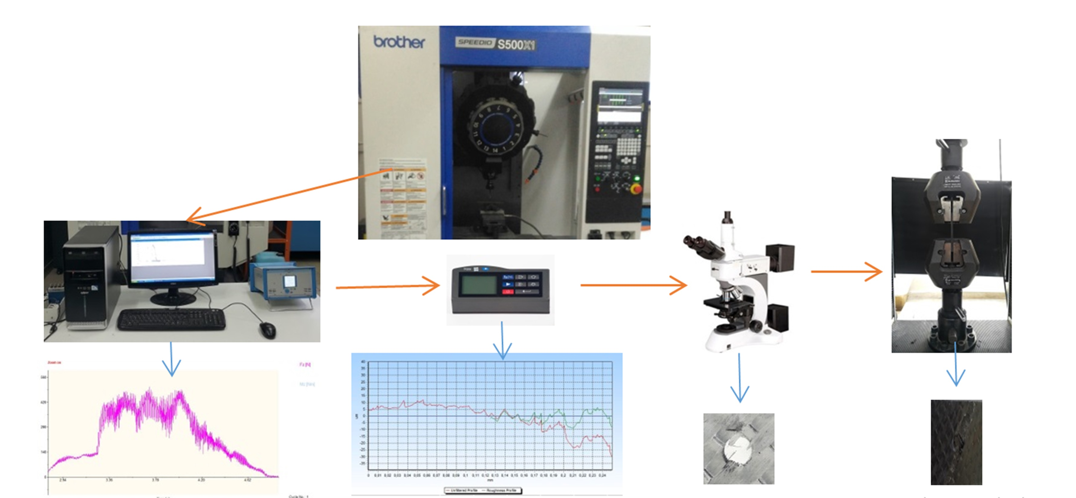
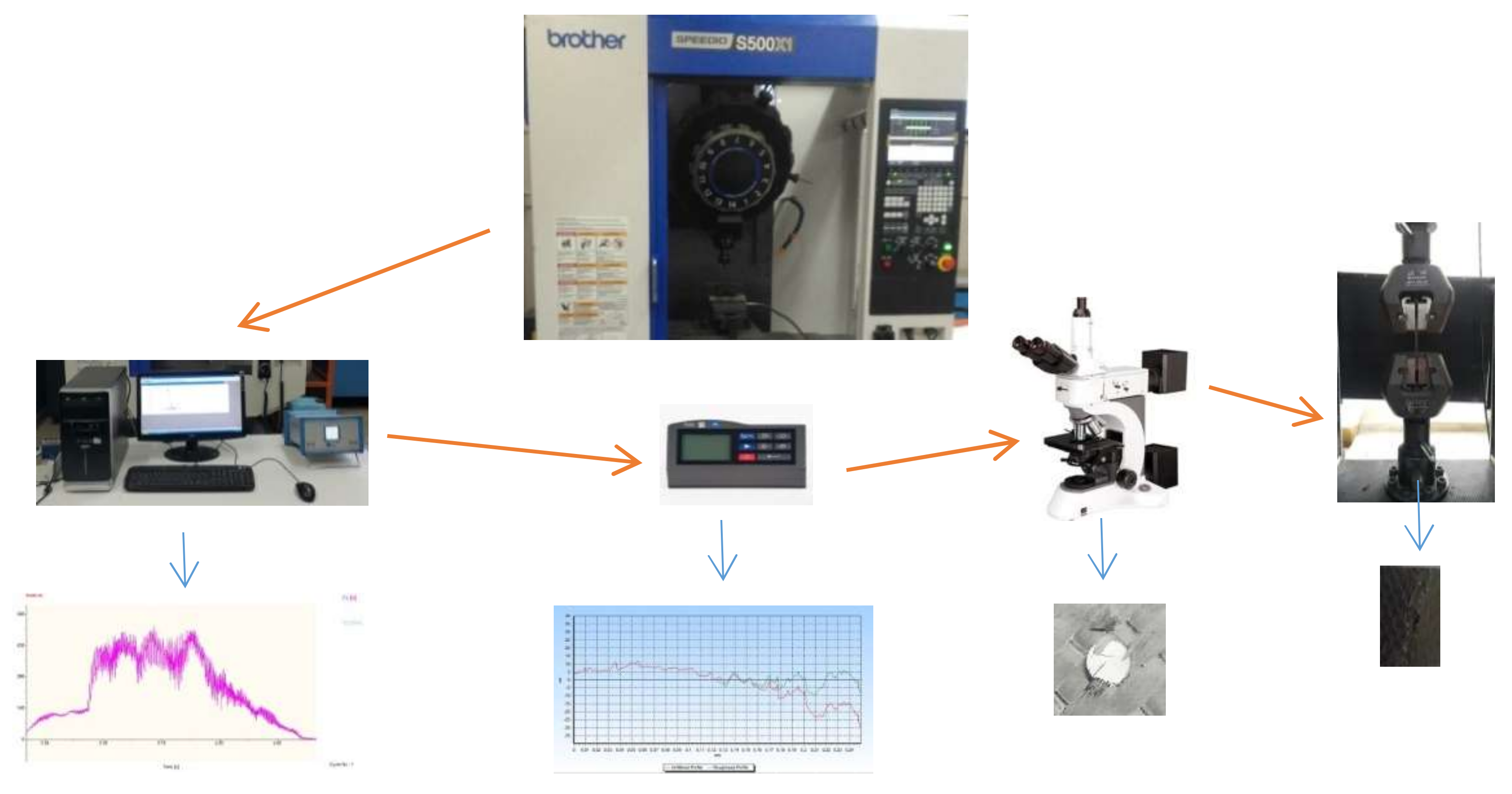
The drilling operations were performed on Computer Numerical Control (CNC) using different drill bit types with spindle speeds of 1000, 3000 and 5000 rpm and feed rates of 0.05, 0.10 and 0.15 mm/rev. The thrust force was measured using Kistler 257B (Kistler Group, Winterthur, Switzerland). The surface roughness of CFRP was measured by Time Surf Tr200. The tensile tests were carried out on Shimadzu Autograph AG-X (Shimadzu, Tokyo, Japan). under displacement at 1 mm/min. The experimental study consisted of 3 steps. In the first step, drilling operations were carried out. In the second step, thrust force, delamination and surface roughness were measured. At the final step, tensile tests were carried out. The flow charts of the experimental setups are shown Figure 1.
2.1. Specimens and Drill Bit
CFRP specimens were produced by Innoma Innovative Materials Technology Corporation. Composite specimens consisted of 11 layer that were ply thickness 0.545 mm of carbon fiber fabric with stacking sequence (+45/−45). The specimen had size of 150 mm × 36 mm × 6 mm according to ASTM D5766-2002. The features of the CFRP specimen are given in Table 1.
2.2. Experimental Measurement
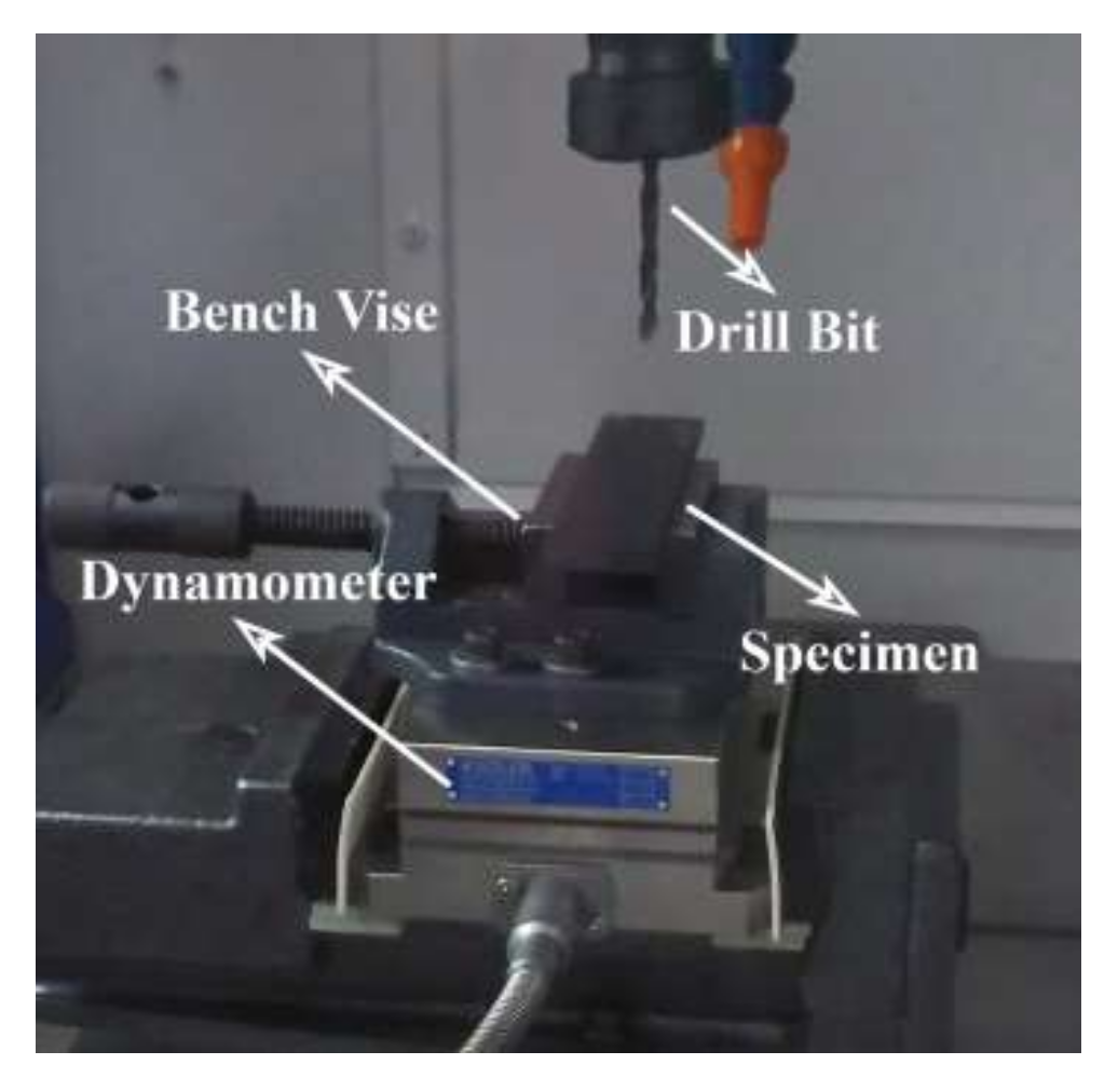
The drilling of CFRP was done on Brother SPEEDIO S500x1 CNC (Brother, Rosengarten, Germany). The drill bit type, feed rate and spindle speed have been selected for the drilling parameters. The drilling setup is shown in Figure 2.
The drilling operations were performed with 3 different drill bits that have 6 mm of diameter, 3 different feed rates and 3 different spindle speeds. The drilling parameters are given Table 3.
The thrust force was measured using Kistler 9257B triaxial force sensor load cell connected to a multichannel amplifier. The thrust force data was recorded by Kistler DynoWare software. The typical thrust force graph is given Figure 3. At the first stage, the cutting edge of the drill bit touches the CFRP and the force increases from zero. At the second stage, the cutting edge of drill bit begins to penetrate the CFRP. This state causes the increase in thrust force rapidly and removes the chip from the material. At the third stage, the length of the cutting edge of drill bit penetrates the materials. It continues until the cutting edge exit through to the bottom of the material. Cutting force decreases slightly during this time. At the fourth stage, cutting edge of the drill bit exits through to the bottom side of the material. This state thrust force decrease in rapidly. At the last stage, drilling operation finishes and thrust force decreases to zero.
The surface quality of CFRP was measured by Time Surf Tr200 (160 μ) hand-held tester with cut off the length of 0.25 mm. Four selected measurement points were 0°, 90°, 270° and 360°. For each position, 3 measurements were taken around the drilled hole. The average surface roughness is calculated as the average of all points values. The surface roughness profile of CFRP drilled with Brad Spur drill bit at 5000 rpm and at 0.05 mm/rev is shown Figure 4.
The delamination factor of top and bottom of drilled specimens were measured with the Medpro Microscopy-MM800TRF (Goodbrother, Ningbo, China). The delamination factor is formulated as in in Figure 5 (where Dmax is diameter of maximum damaged area of drilled hole and D is diameter of hole) [20,21,22,23].
The tensile tests were carried out on Shimadzu Autograph AG-X under displacement at 1 mm/min. The experimental study consists of 3 steps. In the first step, drilling operations were carried out. In the second step, thrust force, delamination and surface roughness were measured. In the final step, tensile tests were carried out.
2.3. ANN Model for Prediction Tensile Load
In this study, tensile load values of CFRP were predicted by modeling with the ANN toolbox using the MATLAB software. The input parameters to predict the tensile load values are drill bit type, spindle speed, and feed rate. ANN model used in this study was tested for the different layer and neuron counts. As a result, the best solution was obtained with the Levenberg-Marquardt forward feedback propagation model with a hidden layer and 10 neurons. The architecture of the one hidden-layer Levenberg-Marquardt feed forward back propagation ANN model is shown in Figure 6.
All data not are used in the training of ANN models. It is preferred that the ratio of the data for training is from 70% to 90% and that for test and validation data is from 30% to 10% [19]. In this study, 70% of the experimental data were used for training, 15% for testing and 15% for validation. ANN model of tensile force of CFRP obtained by drill type, feed rate and spindle speed has been established.
3. Results
3.1. Thrust Force Analyses
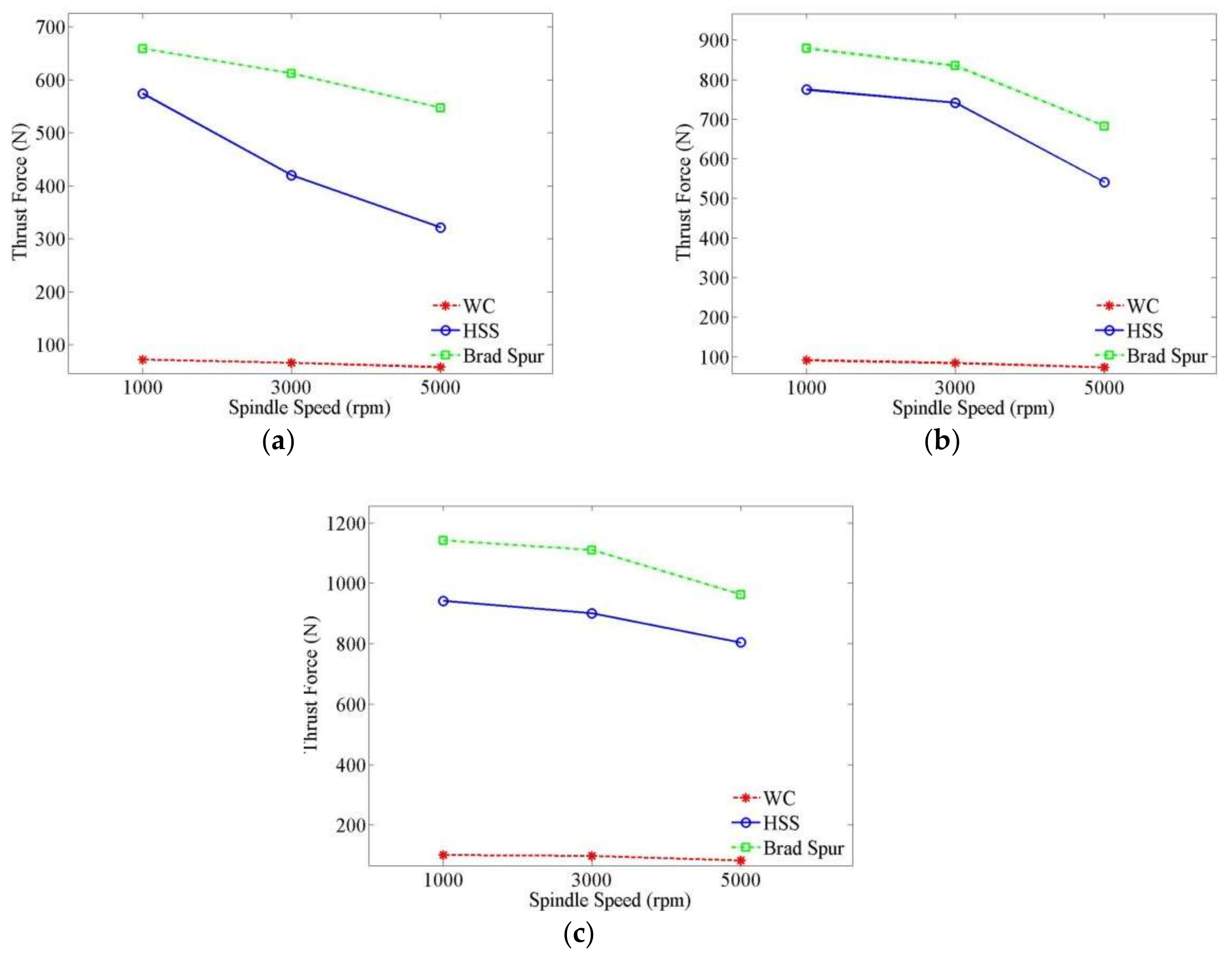
The drilling force is a reaction force the against the displacement of the drill bit. Also, it is known that thrust force, which depends on drilling parameters, is a major factor affecting delamination [24,25,26,27,28,29,30,31,32]. Minimum thrust force is desired at the drilling operation. The variation of drilling parameters on the thrust force drilling of CFRP is shown in Figure 7.
As can be observed from Figure 7 thrust force is affected by drilling parameters. The thrust force is most affected by the drill bit type. The lowest thrust force is obtained from WC drill bit. The coefficient of thermal conductivity of WC is between 63 and 120 W/mK [33,34,35,36] and the coefficient of thermal conductivity of HSS is between 20 and 24 W/mK [37]. Similarly, WC has high wear resistance and high hardness. For this reason, the less wear occurs in the WC drill bit and the heat generated from the friction is moving away from the drilling area rapidly. In this case, drilling operation with the carried-out WC drill bit results in lower drilling forces. The thrust force is decreased with the increase of spindle speed and increased with the increase of feed rate. At low spindle and high feed rates, the drill bit does not have enough time to cut the fibers and the fibers prevents the drill bit from progressing. Therefore, thrust force increases.
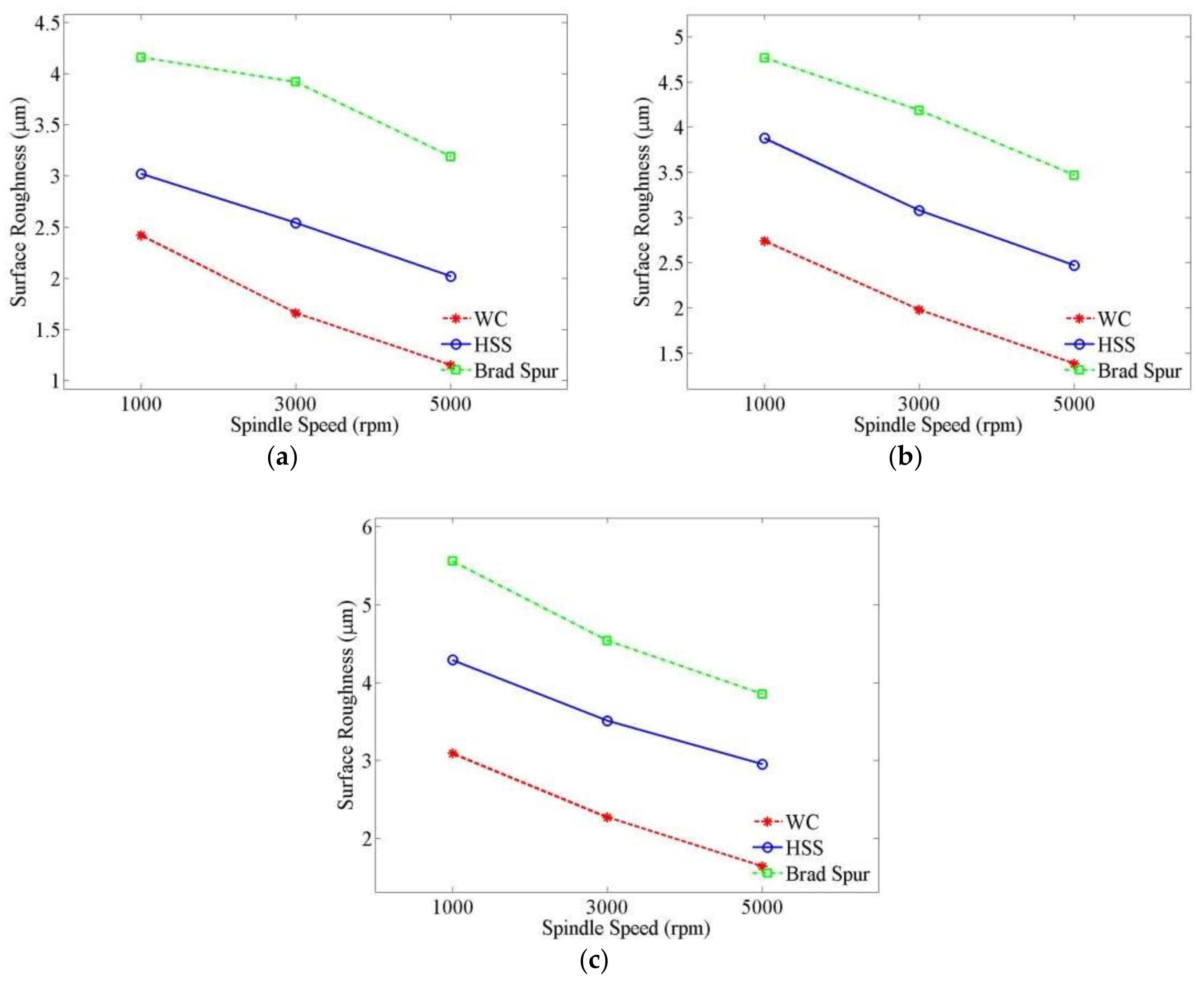
3.2. Surface Roughness Analyses
The surface roughness is the most important factor to determine hole quality [7]. The variation of drilling parameters on the surface roughness of the drilled hole is shown in Figure 8. Because of the reasons explained earlier, the lowest surface roughness was obtained with the WC drill bit. The surface roughness decreased with the increase of spindle speed and increased with the increase of feed rate. At low spindle and high feed rates, the drill bit does not have enough time to cut the fibers and the fibers prevents the drill bit from progressing. As a result, the fibers start breaking and this leads to an increase in surface roughness.
3.3. Delamination Analyses
Delamination is a main problem, which caused the decrease of the tensile strength of CFRP. Delamination occurs due to the thrust of the drill bit during drilling [38]. Delamination images of samples drilled at different parameters with different drill bits are given in Table 4.
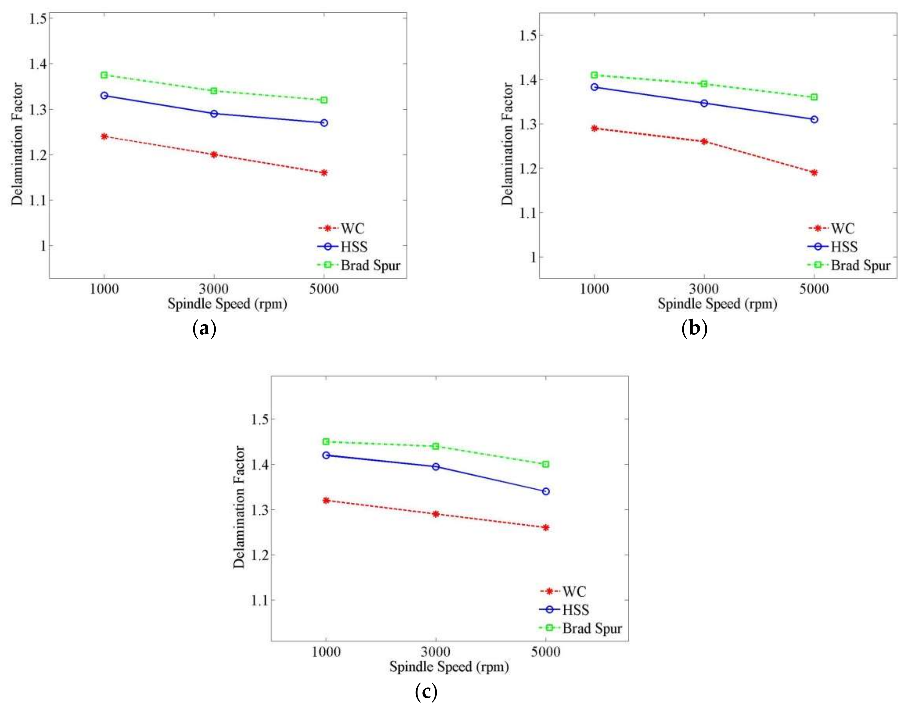
The variation of drilling parameters on delamination in drilling CFRP is examined by using the graphs, which are shown in Figure 9. The figures show that the increase of feed rate increases the delamination factor in drilling of CFRP. It can be said that the drill bit type is the most important parameter affecting delamination in drilling parameters. The best delamination values were observed using WC drill bit and the worst delamination values were observed using Brad Spur drill bit. Because the HSS has a lower thermal conductivity coefficient than the WC, the drilling area heats up rapidly and causes the matrix to melt. Therefore, deformation of the hole increases. At high feed rates, the drill bit pushes the material, and leading to delamination. The effect of spindle speed is negligible.
3.4. Influence of Delamination on Tensile Load
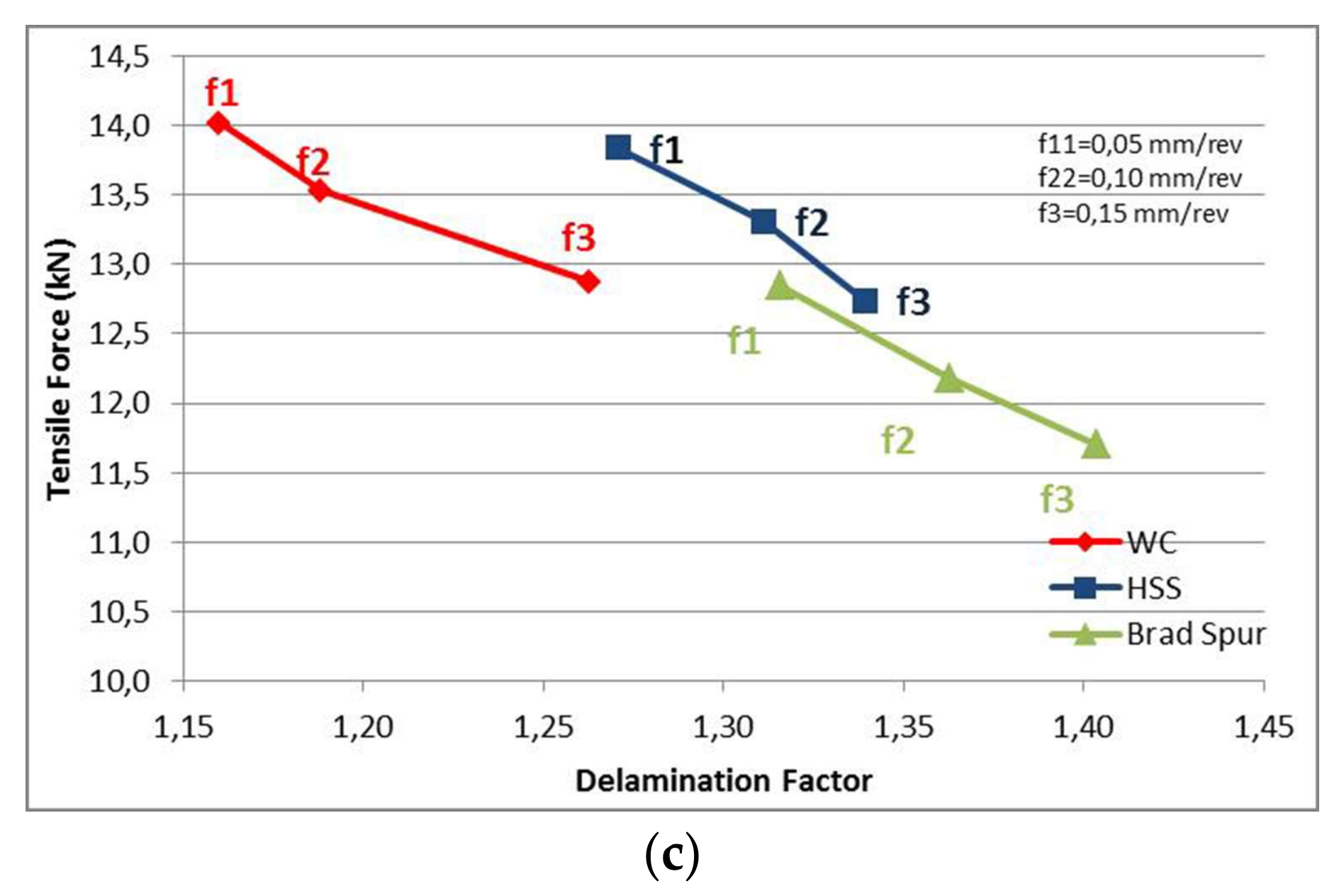
Tensile tests of CFRP specimens with different deformation factors were carried out to determine how much the delamination causes a reduction in tensile load. The variation of delamination on tensile load of CFRP is shown Figure 10. It is obvious that tensile load is directly affected by delamination. Minimum tensile load reduction of CFRP was obtained at high spindle speed and low feed rate in the drilling of CFRP with WC drill bit.
3.5. Prediction of Tensile Load with ANN
The verification figure for testing the reliability of the ANN model is given in Figure 11. The learning abilities of the ANN model are defined by R2 values. The closer the R2 is to the value 1, the greater the learning ability of the ANN (Y). It is seen that all the values are nearest around the linear line when we look at the distribution graph comparing test results and ANN estimation results. In the ANN model, the values of R2 for training, validation and test are 0.99998, 0.99252 and 0.99362, respectively. This means that the predicted results are very close to the experimental results. It can be seen in Figure 11 that with All: R2 = 0.99414, the ANN model can be used for a very high confidence interval in the estimation of the tensile load.
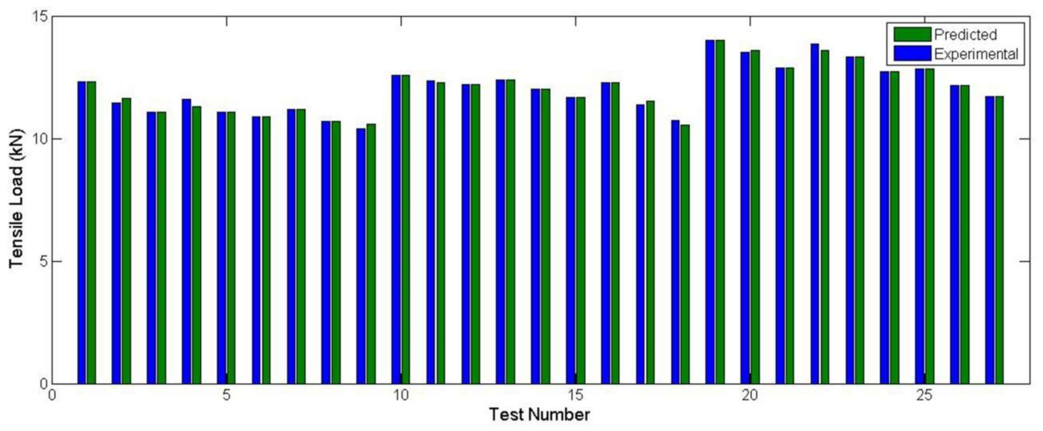
The comparison of predicted and the experimental data are shown as a bar graph in Figure 12. It can be said that predicted and the experimental data are in close agreement with each other. The prediction of tensile load of drilled CFRP is important for open-hole CFRP applications. Also, the ANN model helps with the choice of the drill bit type, feed rate and spindle speed for maximizing the tensile load.
4. Conclusions
This study was carried out to determinate the influence of drilling parameters on the reduction of tensile load of CFRP. The following results were obtained:
- The drilling parameters caused a significant change in the tensile load of the CFRP.
- For all drill bits, increasing of feed rate caused increase of delamination, surface roughness, thrust force, and loss in force, but increasing spindle speed caused decrease of them.
- The maximum tensile load of the CFRP was observed at low feed rate, and high spindle speed drilled with the WC drill bit and the lowest tensile load was observed at the high feed rate, and low spindle speed drilled with the Brad Spur drill bit.
- The drilling parameters showed similar effects on surface roughness, delamination, thrust force and reduction of tensile load. At the same time, it has been shown that these parameters have a linear relationship among themselves.
- If the correct drilling parameters are selected, the decrease in tensile load of CFRP can be up to 25%.
- The results of the ANN model are a match for the experimental results. The ANN model will help engineers to determine correct drilling parameters for maximizing tensile load of CFRP.
Author Contributions
Erol Kilickap conceived and designed the experiments; Burak Yenigun performed the experiments; Erol Kilickap and Burak Yenigun analyzed the data; Burak Yenigun wrote the paper; Erol Kilickap checked the paper.
Conflicts of Interest
The authors declare no conflict of interest.
References
- Kilickap, E.; Yardımeden, A.; Celik, Y.H. Investigation of experimental study of end milling of CFRP composite. Sci. Eng. Compos. Mater. 2015, 22, 89–95. [Google Scholar] [CrossRef]
- Solmaz, M.Y.; Topkaya, T. Progressive Failure Analysis in Adhesively, Riveted, and Hybrid Bonded Double-Lap Joints. J. Adhes. 2013, 89, 822–836. [Google Scholar] [CrossRef]
- Government Accountability Office. GAO Status of FAA’s Actions to Oversee the Safety of Composite Airplanes; AVIATION SAFETY; Government Accountability Office: Washington, DC, USA, 2011.
- Huang, Z.; Wu, Y.J.; Zhang, C. Bamboo strengthened with carbon fiber reinforced polymer for the substitutes of steel substructures. Key Eng. Mater. 2012, 17, 233–237. [Google Scholar] [CrossRef]
- Celik, Y.H.; Kilickap, E.; Yardımeden, A. Estimate of cutting forces and surface roughness in end milling of glass fiber reinforced plastic composites using fuzzy logic system. Sci. Eng. Compos. Mater. 2014, 21, 435–443. [Google Scholar] [CrossRef]
- Hocheng, H.; Tsao, C. Effects of Special Drill Bits on Drilling-Induced Delamination of Composite Materials. Int. J. Mach. Tools Manuf. 2006, 46, 1403–1416. [Google Scholar] [CrossRef]
- Kilickap, E. Analysis and Modeling of Delamination Factor in Drilling Glass Fiber Reinforced Plastic Using Response Surface Methodology. J. Compos. Mater. 2011, 45, 727–736. [Google Scholar] [CrossRef]
- Wong, T.L.; Wu, S.M.; Croy, G.M. An analysis of delamination in drilling composite materials. In Proceedings of the 14th National SAMPE Technical Conference, Atlanta, GA, USA, 12 October 1982; Volume 47, pp. 481–483. [Google Scholar]
- Tao, C.; Qiu, J.; Yao, W.; Ji, H. The effect of drilling-induced delamination on tensile strength and prediction of residual strength of carbon fiber-reinforced polymer laminate. J. Compos. Mater. 2016, 50, 3373–3384. [Google Scholar] [CrossRef]
- Langella, A.; Durante, M. Comparison of tensile strength of composite material elements with drilled and molded-in holes. Appl. Compos. Mater. 2008, 15, 227–239. [Google Scholar] [CrossRef]
- Dilli Babu, G.; Sivaji Babu, K.; Uma Maheswar Gowd, B. Determination of delamination and tensile strength of drilled natural fiber reinforced composites. Appl. Mech. Mater. 2014, 592, 134–138. [Google Scholar] [CrossRef]
- Nasir, A.A.; Azmi, A.I.; Khalil, A.N.M. Measurement and optimisation of residual tensile strength and delamination damage of drilled flax fibre reinforced composites. Measurement 2015, 75, 298–307. [Google Scholar] [CrossRef]
- Mishra, R.; Malik, J.; Singh, I.; Davim, J.P. Neural network approach for estimating the residual tensile strength after drilling in uni-directional glass fiber reinforced plastic laminates. Mater. Des. 2010, 31, 2790–2795. [Google Scholar] [CrossRef]
- De Filippis, L.A.C.; Serio, L.M.; Facchini, F.; Mummolo, G.; Ludovico, A.D. Prediction of the vickers microhardness and ultimate tensile strength of AA5754 H111 friction stir welding butt joints using artificial neural network. Materials 2016, 9, 915. [Google Scholar] [CrossRef] [PubMed]
- Sevim, D.; Fidan, Ş.; Polat, S.; Oktay, H. Experimental and Articial Neural Network Based Studies on Thermal Conductivity of Lightweight Building Materials. Eur. J. Tech. 2017, 7, 33–41. [Google Scholar] [CrossRef]
- Behera, R.R.; Ghadai, R.K.; Kalita, K.; Banerjee, S. Simultaneous prediction of delamination and surface roughness in drilling GFRP composite using ANN. Int. J. Plast. Technol. 2016, 20, 424–450. [Google Scholar] [CrossRef]
- Sahin, Y. Yapay Sinir Ağları ile Al/Sic Kompozit Malzemenin Yüzey Pürüzlülüğünün Tahmini. Gazi Üniversitesi Mühendislik-Mimarlık Fakültesi Dergisi. 2014, 29. [Google Scholar] [CrossRef]
- Kilickap, E.; Yardimeden, A.; Çelik, Y.H. Mathematical Modelling and Optimization of Cutting Force, Tool Wear and Surface Roughness by Using Artificial Neural Network and Response Surface Methodology in Milling of Ti-6242S. Appl. Sci. 2017, 7, 1064. [Google Scholar] [CrossRef]
- Liu, D.; Tang, Y.; Cong, W.L. A review of mechanical drilling for composite laminates. Compos. Struct. 2012, 94, 1265–1279. [Google Scholar] [CrossRef]
- Shah, D.U.; Schubel, P.J.; Clifford, M.J. Can flax replace E-glass in structural composites? A small wind turbine blade case study. Compos. Part B Eng. 2013, 52, 172–181. [Google Scholar] [CrossRef]
- Palanikumar, K.; Prakash, S.; Shanmugam, K. Evaluation of delamination in drilling GFRP composites. Mater. Manuf. Process. 2008, 23, 858–864. [Google Scholar] [CrossRef]
- Tsao, C.C.; Hocheng, H. Computerized tomography and C-Scan for measuring delamination in the drilling of composite materials using various drills. Int. J. Mach. Tools Manuf. 2005, 45, 1282–1287. [Google Scholar] [CrossRef]
- Singh, I.; Bhatnagar, N.; Viswanath, P. Drilling of uni-directional glass fiber reinforced plastics: Experimental and finite element study. Mater. Des. 2008, 29, 546–553. [Google Scholar] [CrossRef]
- Tsao, C.C.; Hocheng, H.; Chen, Y.C. Delamination reduction in drilling composite materials by active backup force. CIRP Ann. Manuf. Technol. 2012, 61, 91–94. [Google Scholar] [CrossRef]
- Arul, S.; Vijayaraghavan, L.; Malhotra, S.K.; Krishnamurthy, R. Influence of tool material on dynamics of drilling of GFRP composites. Int. J. Adv. Manuf. Technol. 2006, 29, 655–662. [Google Scholar] [CrossRef]
- Jain, S.; Yang, D.C. Effects of feed rate and chisel edge on delamination in composites drilling. J. Eng. Ind. 1993, 115, 398–405. [Google Scholar] [CrossRef]
- Koenig, W.; Wulf, C.; Grass, P.; Willerscheid, H. Machining of fibre reinforced plastics. CIRP Ann. Manuf. Technol. 1985, 34, 537–548. [Google Scholar] [CrossRef]
- Brinksmeier, E.; Fangmann, S.; Rentsch, R. Drilling of composites and resulting surface integrity. CIRP Ann. Manuf. Technol. 2011, 60, 57–60. [Google Scholar] [CrossRef]
- Teti, R. Machining of composite materials. CIRP Ann. Manuf. Technol. 2002, 51, 611–634. [Google Scholar] [CrossRef]
- Franke, V. Drilling of long fiber reinforced thermoplastics—Influence of the cutting edge on the machining results. CIRP Ann. Manuf. Technol. 2011, 60, 65–68. [Google Scholar] [CrossRef]
- Schulze, V.; Becke, C.; Pabst, R. Specific machining forces and resultant force vectors for machining of reinforced plastics. CIRP Ann. Manuf. Technol. 2011, 60, 69–72. [Google Scholar] [CrossRef]
- Stein, J.M.; Dornfeld, D.A. Burr formation in drilling miniature holes. CIRP Ann. Manuf. Technol. 1997, 46, 63–66. [Google Scholar] [CrossRef]
- Pierson, H.O. Handbook of Refractory Carbides & Nitrides: Properties, Characteristics. Processing and Applications; William Andrew: Park Ridge, NJ, USA, 1996. [Google Scholar]
- Shackelford, J.F.; Alexander, W. CRC Materials and Engineering Handbook, 3rd ed.; CRC Press: Boca Raton, FL, USA, 2000. [Google Scholar]
- Schultrich, B.; Poebnecker, W. Thermal conductivity of cemented carbides. J. Therm. Anal. Calorim. 1988, 33, 305–310. [Google Scholar] [CrossRef]
- Wang, H.; Webb, T.; Bitler, J.W. Study of thermal expansion and thermal conductivity of cemented WC–Co composite. Int. J. Refract. Met. Hard Mater. 2015, 49, 170–177. [Google Scholar] [CrossRef]
- Ketin, M. Sirius-High Speed Steel. Available online: www.mkb.be/Qualities/MK-Sirius.pdf (accessed on 5 November 2017).
- Bosco, M.A.J.; Palanikumar, K.; Prasad, B.D.; Velayudham, A. Influence of machining parameters on delamination in drilling of GFRP-armour steel sandwich composites. Procedia Eng. 2013, 51, 758–763. [Google Scholar] [CrossRef]
Figure 1.
Flow chart of experimental setup.

Figure 2.
The drilling setup.

Figure 3.
Typical thrust force graphic.
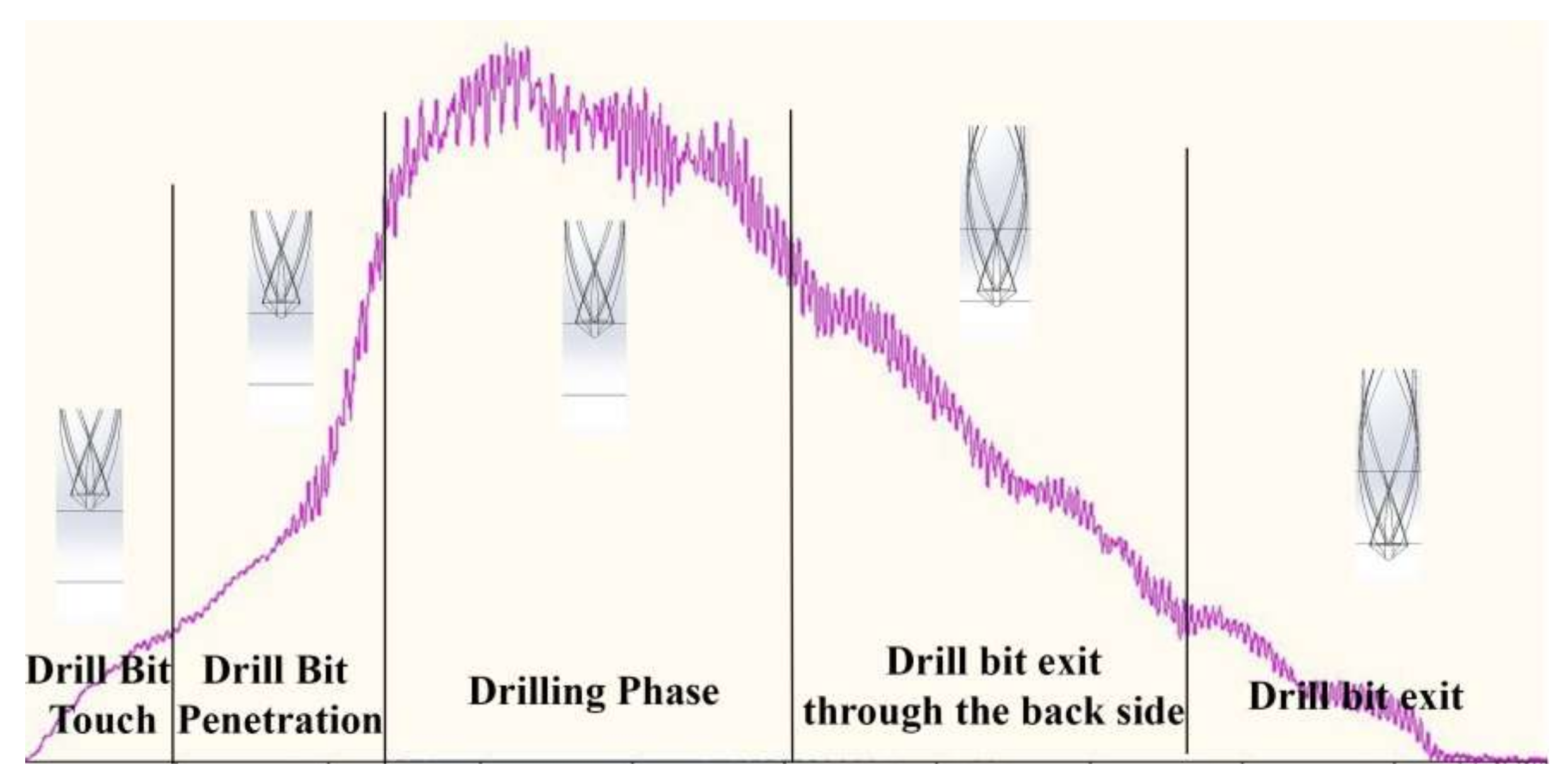
Figure 4.
Surface Roughness profile drilled with Brad Spur drill bit at 5000 rpm and at 0.05 mm/rev.
Figure 4.
Surface Roughness profile drilled with Brad Spur drill bit at 5000 rpm and at 0.05 mm/rev.

Figure 5.
Delamination factor.

Figure 6.
Artificial neural network (ANN) architecture for predict model.
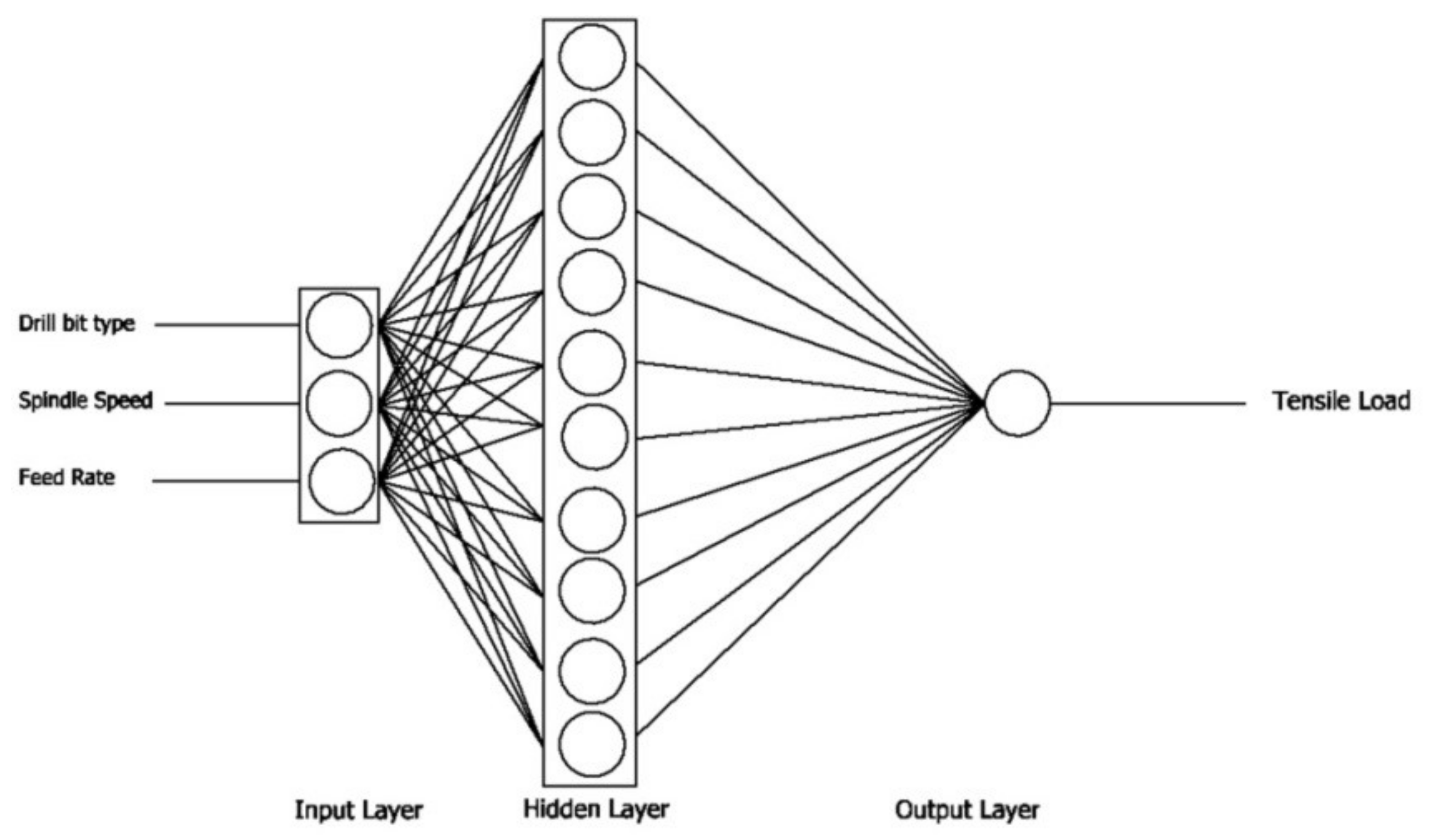
Figure 7.
Variation of drilling parameters on thrust force: (a) 0.05 mm/rev; (b) 0.10 mm/rev; (c) 0.15 mm/rev.
Figure 7.
Variation of drilling parameters on thrust force: (a) 0.05 mm/rev; (b) 0.10 mm/rev; (c) 0.15 mm/rev.

Figure 8.
Variation of drilling parameters on surface roughness: (a) 0.05 mm/rev; (b) 0.10 mm/rev; (c) 0.15 mm/rev.
Figure 8.
Variation of drilling parameters on surface roughness: (a) 0.05 mm/rev; (b) 0.10 mm/rev; (c) 0.15 mm/rev.

Figure 9.
Variation of drilling parameters on delamination: (a) 0.05 mm/rev; (b) 0.10 mm/rev; (c) 0.15 mm/rev.
Figure 9.
Variation of drilling parameters on delamination: (a) 0.05 mm/rev; (b) 0.10 mm/rev; (c) 0.15 mm/rev.

Figure 10.
Variation of delamination factor on tensile load: (a) 1000 rev/min; (b) 3000 rev/min; (c) 5000 rev/min.
Figure 10.
Variation of delamination factor on tensile load: (a) 1000 rev/min; (b) 3000 rev/min; (c) 5000 rev/min.


Figure 11.
The relationship between the measured and predicted tensile loads of carbon fiber reinforced plastics (CFRP).
Figure 11.
The relationship between the measured and predicted tensile loads of carbon fiber reinforced plastics (CFRP).
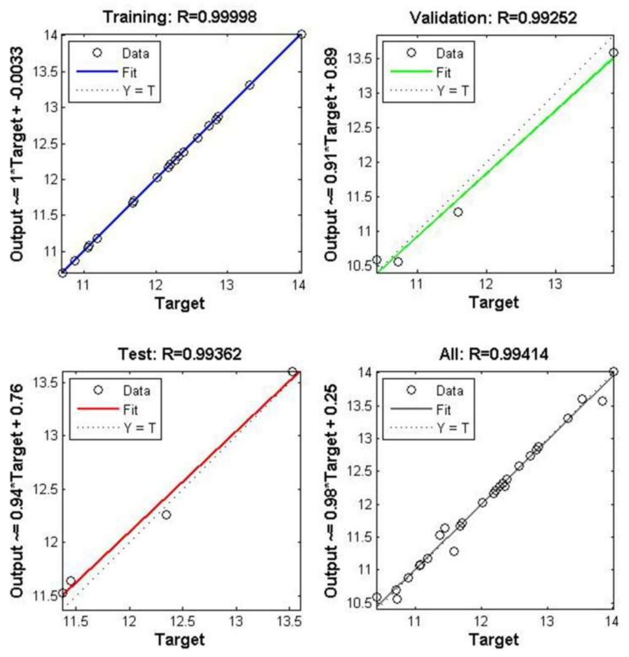
Figure 12.
Comparison of experimental and predicted tensile loads of CFRP.


Table 1.
The features of composites.
| Properties. | Fiber | Resin |
|---|---|---|
| Type | Carbon | Polyester |
| Volume Rate (%) | 55 | 45 |
| Tensile Strength (Mpa) | 66.47 | |
| Number of Layers | 11 | |
| Ply Thickness (mm) | 0.545 | |
| Fiber Orientation | (+45/−45) | |
Table 2.
The properties of drill bits.
| Properties | High Speed Steel | Brad Spur | Tungsten Carbide |
|---|---|---|---|
| Drill Bit Type | Twist | Twist | Twist |
| Point Angle (°) | 118 | - | 140 |
| Helix Angle (°) | 30 | 30 | 30 |
| Material | High Speed Steel | Tungsten Carbide | |
Table 3.
Drilling parameters.
| Level | Feed Rate(mm/rev) | Spindle Speed (rev/min) |
|---|---|---|
| 1 | 0.05 | 1000 |
| 2 | 0.10 | 3000 |
| 3 | 0.15 | 5000 |
Table 4.
The Delamination images of samples.
| Drill Bit | Rpm | 0.05 mm/rev | 0.10 mm/rev | 0.15 mm/rev | |||
|---|---|---|---|---|---|---|---|
| Entrance | Exit | Entrance | Exit | Entrance | Exit | ||
| Brad Spur | 1000 |  |  |  |  |  |  |
| 3000 |  |  |  |  |  |  | |
| 5000 |  |  |  |  |  |  | |
| HSS | 1000 |  |  |  |  |  |  |
| 3000 |  |  |  |  |  |  | |
| 5000 |  |  |  |  |  |  | |
| WC | 1000 |  |  |  |  |  |  |
| 3000 |  |  |  |  |  |  | |
| 5000 |  |  |  |  |  |  | |
© 2018 by the authors. Licensee MDPI, Basel, Switzerland. This article is an open access article distributed under the terms and conditions of the Creative Commons Attribution (CC BY) license (http://creativecommons.org/licenses/by/4.0/).
Share and Cite
MDPI and ACS Style
Yenigun, B.; Kilickap, E. Prediction of the Tensile Load of Drilled CFRP by Artificial Neural Network. Appl. Sci. 2018, 8, 549. https://doi.org/10.3390/app8040549
AMA Style
Yenigun B, Kilickap E. Prediction of the Tensile Load of Drilled CFRP by Artificial Neural Network. Applied Sciences. 2018; 8(4):549. https://doi.org/10.3390/app8040549
Chicago/Turabian StyleYenigun, Burak, and Erol Kilickap. 2018. "Prediction of the Tensile Load of Drilled CFRP by Artificial Neural Network" Applied Sciences 8, no. 4: 549. https://doi.org/10.3390/app8040549
Note that from the first issue of 2016, this journal uses article numbers instead of page numbers. See further details here.