Reverberation-Ray Matrix Analysis and Interpretation of Bending Waves in Bi-Coupled Periodic Multi-Component Beams


School of Civil Engineering and Mechanics, Lanzhou University, and Key Laboratory of Mechanics on Disaster and Environment in Western China, Ministry of Education, Lanzhou 730000, China
*
Author to whom correspondence should be addressed.
Appl. Sci. 2018, 8(4), 531; https://doi.org/10.3390/app8040531
Submission received: 15 January 2018
/
Revised: 22 March 2018
/
Accepted: 28 March 2018
/
Published: 30 March 2018
(This article belongs to the Section Acoustics and Vibrations)
Abstract
:Featured Application
The method of reverberation-ray matrix (MRRM) and the interpretation of bending waves proposed in this paper provide respectively analysis method and profound knowledge for bending waves in bi-coupled periodic multi-component beams. These achievements will push forward the applications of bi-coupled periodic multi-component beams in wave filtering and vibration isolation.
Abstract
Most existing research on periodic beams concerns bending waves in mono-coupled and bi-coupled periodic mono-component beams with the unit cell containing only one beam segment, and very few works on bi-coupled periodic multi-component beams with the unit cell containing more than one beam segments study the bending waves in structures with only binary unit cells. This paper presents the method of reverberation-ray matrix (MRRM) as an alternative theoretical method for analyzing the dispersion characteristics of bending waves with the wavelength greater than the size of the cross-sections of all components in bi-coupled periodic multi-component beams. The formulation of MRRM is proposed in detail with its numerically well-conditioned property being emphasized, which is validated through comparison of the results obtained with the counterpart results by other methods for exemplified bi-coupled periodic beams. Numerical examples are also provided to illustrate the comprehensive dispersion curves represented as the relations between any two among three in frequency, wavenumber (wavelength) and phase-velocity for summarizing the general features of the dispersion characteristics of bending waves in bi-coupled periodic multi-component beams. The effects of the geometrical and material parameters of constituent beams and the unit-cell configuration on the band structures are also demonstrated by numerical examples. The most innovative finding indicated from the dispersion curves is that the frequencies corresponding to the Brillouin zone boundary may not be the demarcation between the pass-band and stop-band for bending waves in bi-coupled periodic multi-component beams.
1. Introduction
A periodic structure consists of repeated unit cells which are joined together end-to-end/side-by-side [1]. The most important property determined by this constructional feature is that the frequency domain of the waves falls into pass-bands and stop-bands that correspond respectively to those frequencies at which waves propagate without attenuation and to others at which waves attenuate with no propagation [1,2,3]. Consequently, periodic structures may have wide applications in various fields requiring wave filtering or vibration isolation, which drives the investigations of wave propagation in periodic structures in various scientific fields such as solid-state physics, electrical engineering and mechanical engineering, that are concerned with electron waves, electromagnetic waves, and electric current and elastic waves [2,3].
As one of the most important periodic structures, a periodic beam consists of beam segments possessing frequency bands of bending waves. Since the beam structure is a basic component in engineering and the bending wave is one of the main vibration forms and noise origins in engineering structures [4], the study of bending waves in periodic beams hence provides a method for vibration control and noise reduction in engineering structures, e.g., railway trains and tracks. Using the elastically point-supported, flexibly interconnected periodic beam and Timoshenko beam theory (TBT) or Euler–Bernoulli beam theory (EBT) to model railway train, Sakuma et al. [5] analyzed the harmonic and time-history responses of high-speed trains and train-like articulated systems travelling in confined fluid. Adopting the elastically point-supported periodic beam and based on the TBT, EBT or extended beam theory to model the railway track, Gry and Gontier [6] and Hosking and Milinazzo [7] studied bending-wave propagation together with the forced responses of railway tracks and floating ladder tracks, respectively. Sheng et al. [8] derived the propagation constant equations and used them for ballasted track to study the harmonic responses to steadily moving or static loads [8] and to discuss the propagation and resonance properties [9]. Using the Green’s function approach, Mazilu [10] predicted the interaction between a simple moving vehicle and the infinite periodic Timoshenko tract beam. Employing the elastically point-supported periodic Euler–Bernoulli beam to model the direct fixation track and the periodic beam with a unit cell consisting of a double beam on an elastic foundation to model the floating slab track, Gupta and Degrande [11] computed the transfer functions of the coupled track–tunnel–soil system and the dynamic forces accounting for the interaction between the moving vehicle and the periodic track. Although in recent years active periodic beams with smart components have been proposed on the basis of initially presented passive periodic beams made of only elastic materials in order for the bending-wave bands to be adjusted intelligently for controlling vibration and reducing noise in a more effective way, in this paper we still exclusively consider passive periodic beams in which only the construction of unit cell affects the band properties and the dispersion characteristics remain after the unit cell is determined. This is because there are still pending problems on this research objective, as will be summarized after an extensive literature review.
Passive periodic elastic beams may fall into two categories according to the minimum number of coupling coordinates between the structural beams, i.e., mono-coupled and bi-coupled periodic beams that have one and two minimum coupling coordinates, respectively [1,12]. For example, as the flexible interconnection of the articulated train system in Reference [5] transfers one or two generalized forces, the analysis models are mono-coupled and bi-coupled periodic beams, respectively. Mono-coupled periodic beams are mainly introduced in the form of periodic multi-span beams. There already exist extensive investigations on the bending waves in mono-coupled periodic beams, and without exception periodic multi-span beams [1,4,12,13,14,15,16,17,18,19,20], have led to the very wide applications of these structures in engineering practice, such as periodically supported bridges for instance. Thus, here we focus on bi-coupled periodic beams in this paper. Note that there are five kinds of bi-coupled periodic beams that have been presented so far: (1) a periodic beam composed of a uniform beam periodically attached with elastic supports with/without lumped masses; (2) a periodic beam composed of a uniform beam periodically attached with mass-spring systems (together with lumped masses and/or elastic supports); (3) a periodic beam made of periodically arranged two or more beam segments of different material/geometrical properties; (4) a periodic beam formed by combining the third and the first concepts; (5) a periodic beam formed by combining the third and the second concepts. It should be pointed out that periodic beams formed by combining the first and the second concepts belong to the second kind itself. It should also be emphasized that the second and the fifth kinds of bi-coupled periodic beams introduce a locally resonant mechanism [2] other than the Bragg scattering mechanism [2,3] into the formation of band gaps, so that low-frequency band gaps may possibly provide a new way in controlling low-frequency waves/vibrations without using unrealistically large structures. Note further that the first two kinds of periodic beams all have unit cells containing only one beam segment with attachments, and these structures are referred here to as bi-coupled periodic mono-component beams. In contrast, the last three kinds of periodic beams all have unit cells containing more than one beam segments without or with attachments, which are referred to here as bi-coupled periodic multi-component beams. Up until now, the bending waves in all the five types of bi-coupled periodic beams have been of concern.
First, the bending waves in the first kind of periodic beams have gained attention since the 1960s. Some literature considered the bending wave/vibration properties of infinite/finite periodic beams. For the periodic beams supported by translational/rotational springs: Lin [21] pioneered the analysis of the natural frequencies and modes of finite beams; then, Mead [16] derived the dispersion equation of characteristic bending waves in the infinite beams and discussed the interaction between characteristic bending waves and the alternating pressure field using the receptance method (RM); Zhu and Cheng [22] constructed the mutual variational principle of bending wave propagation in periodic structures, which provided the theoretical basis for the corresponding h-type finite element method (FEM). With the h–p hybrid FEM, Bardell et al. [17] analyzed the phase constant curves of the bending waves in infinite periodic Euler–Bernoulli beams; Romeo and Luongo [23] presented the design of periodic undamped and damped beams aimed at reducing the transmitted vibrations by referring the bi-dimensional analytical maps of the single unit free-wave propagation domains (stop, pass and complex domains) as the optimal choice of the cell properties and ordering. For periodic beams supported by translational/rotational springs with lumped masses: Wei and Petyt [18,19] introduced the extended Rayleigh–Ritz method to analyze the pass band properties and the natural properties of infinite and finite periodic structures, respectively; Brunskog [24] discussed the propagation properties of bending waves. For periodic beams with only added masses, Domadiya et al. [25] investigated numerically and experimentally the dispersion curves and the transmission loss coefficient of infinite and semi-infinite beams, respectively. Others consider the responses of infinite/finite periodic beams under external excitation: Ungar [26] discussed the propagation constants of bending waves in infinite periodic beams supported by translational springs and analyzed the steady-state response at the supported joint under harmonic loads by considering the effect of damping and fluid loads; using Fourier transform, Belotserkovskiy [27] analyzed the transient responses of infinite periodic Euler–Bernoulli beams with translational springs under a concentrated load; Cheng et al. [28,29] presented the wavenumber-harmonic method to analyze the frequency responses and sound radiations of a translational point-spring supported periodic Timoshenko beam subjected to a convected or travelling harmonic loading by considering the fluid-loading effect and discussing the influences of the spring support and the loading speed; Mead and Pujara [30] and Mead and Mallik [31] analyzed the steady-state response of infinite periodic Euler–Bernoulli beams with translational/rotational springs under alternating random loads by the space harmonic method and complex modal method, respectively; Mead [32] proposed a method to analyze the propagation constants of bending waves in infinite-period Timoshenko beams attached with translational/rotational springs and lumped-mass and their responses to an alternating harmonic pressure field; Mead and Yaman [33] analyzed the steady-state responses of infinite periodic beams with translational/rotational spring supports or lumped-mass under harmonic loads based on propagation constants.
Second, the bending waves in the second periodic beams classified above have been studied ever since 2005. The main concerns have been the band gaps and frequency responses of bending waves caused by Bragg scattering and locally resonant in infinite/finite periodic beams. For periodic beams with single DOF (degree-of-freedom) resonators: Yu et al. [34] and Liu et al. [35] analyzed the complex band structures using the transfer matrix method (TMM) based on TBT and EBT, respectively. Yu et al. [34] further analyzed the frequency response function (FRF, i.e., transmission) using the FEM and validated the results by experiments. Liu et al. [35] further analyzed the FRF using TMM, particularly concerning the influence of different local resonators, and summarized some design guidelines for this kind of structure. Xiao et al. [36] analyzed the complex band structures by the spectral element method (SEM) and examined the effects of various system parameters on band-gap behavior. The band formation mechanisms and formulas determining the transition and near-coupling conditions between local resonance and Bragg scattering were obtained. Sharma and Sun [37] studied the attenuation behavior of low-frequency waves in sandwich beams by closed form expression obtained from a phased array approach and verified the results by FEM. For periodic beams with two DOF resonators: Wang et al. [38] analyzed the band structures by TMM and the FRF by FEM, respectively, with a simplified model proposed to determine the edge frequencies of the band gaps and to enhance the understanding of the locally resonant mechanism. Pai et al. [39] calculated the dynamic behaviors by FEM and explained how the spring-mass-damper subsystem created two stopbands and negative effective mass and stiffness. For periodic beams with three DOF resonators: Wang et al. [40] studied the suppression of flexural vibration theoretically and numerically by the dispersion relation obtained using Hamilton’s principle and Bloch’s theorem. For periodic beams with more than three DOF resonators: Wang et al. [41] analyzed the band structures and characteristic modes of infinite periodic beams using the lumped mass method (LMM) and calculated the FRF of finite periodic beams using the FEM, based on three-node triangular plane stress elements. The theoretical FRF was validated by experimental measurements on a finite periodic beam specimen. For bending waves in a uniform beam attached with both translational/rotational spring supports and mass-spring resonators and with/without lumped mass: Lin and McDaniel [42] analyzed the FRF of a finite periodic beam by TMM based on EBT; based on Winkler’s foundation model and EBT, Yu et al. [43] studied the complex band structures and FRF of periodic beams on elastic foundations attached also with a locally-resonant mass-spring system; Raghavan and Phani [44] derived by RM the closed-form expressions for the location and width of sub-Bragg bandgaps, obtained the rigid body modes of the unit cell setting the bounding frequencies for local resonance bandgaps, and validated these results by experiments.
Third, the above-classified third kind of periodic beams have also received much attention. The main concern was the flexural wave/vibration in and frequency response of infinite/finite period beams. For periodic binary beams with two kind of materials: Lee et al. [45] proposed a basis theory of bending wave propagation; Han et al. [46] and Ni et al. [47] introduced a modified transfer matrix method (MTM) by transforming the state parameters of TMM into four initial parameters based on EBT and TBT, respectively; Tao and Liao [48] investigated the effects of the clamped boundary condition and disturbance on the flexural wave propagation using the method of multiple reflections; de Miranda and Dos Santos [49] investigated theoretically using FEM, SEM, the wave finite element method (WFEM), the wave spectral element method (WSEM), the conventional and improved plane wave expansion (PWE) method and experimentally the forced response and band structure based on EBT. Cheng et al. [50] investigated complex dispersion relations and the evanescent wave modes by their developed extended differential quadrature element method (EDQEM). For periodic binary beams with two kinds of cross-sections: Díaz-de-Anda et al. [51] analyzed the normal-mode frequencies and amplitudes of finite beams using TMM based on TBT, which were compared with the results based on EBT and were verified by experimental results from electromagnetic acoustic transducer (EMAT) measurements; Domadiya et al. [25] investigated numerically and experimentally the dispersion curves of periodic beams and the transmission loss coefficient of semi-periodic beams, respectively; Gao et al. [52] used TMM to explore the natural frequencies and the band-gap properties of the periodic beams based on the EBT and TBT, and verified the results by FEM and an experiment, with attention on the influences of the cross-section ratios and the length ratios on the dynamic properties. For periodic binary beams with two kind of materials of different cross-sections: Wen et al. [53,54] calculated the band structures of an infinite periodic beam with the PWE and the vibration attenuation spectra of a corresponding finite sample by FEM. The theoretical results were validated by vibration experiment, and a vibration isolation structure was designed based on these investigations. Xiang and Shi [55] proposed the differential quadrature method (DQM) for the analysis of band structures and properties with comparing the effects of TBT and EBT on the results. The influences of geometrical parameters and material parameters on the band-gap properties were discussed. For periodic beams with continuously changed parameters, Ying and Ni [56] proposed a double-expansion method for the frequency response of finite-length beams under harmonic excitation. For practical engineering applications of periodic binary beams: Richards and Pines [57] analyzed the propagation parameters and the frequency spectra based on EBT using SEM aiming at the reduction of the gear mesh flexural vibration using a periodic drive shaft. The influences of added inertia, boundary conditions and structural configuration were also considered. The analytical results were verified by experimental data, which indicated the real attenuation efficiency. Asiri et al. [58] designed periodic binary beams for supporting the ocean platform to reduce the propagation of the ocean noise to the platform, analyzed with a method based on EBT and TMM the band structure and the frequency response of the infinite and finite periodic binary beams, respectively, and verified the results by comparing them with an experiment of the scaled model of the ocean platform.
Fourth, bending waves in periodic beams of the above-classified fourth kind have been investigated since the 1980s. All the unit cells in the numerical examples considered up to now were binary. As the attachments are lumped, McDaniel and Carroll [20] analyzed the band structure of infinite periodic beams supported by translational springs and discussed the free vibration properties based on the EBT and the TMM. As the attachments are distributed, Tassilly [59] analyzed the band structures of periodic beams with spring and viscously-damped supports based on EBT and Floquet theory. Gei et al. [60] studied the band structures of prestressed periodic perfect and defected beams on an elastic foundation based on EBT, with special attention on the effects of prestress on the position/width of the band-gaps. The band-gap localized modes and effective negative mass effects of periodic perfect beams on an elastic foundation with an additional mass were also discussed using a Green’s function formulation. Xiang and Shi [61] analyzed the band gaps and the dynamic responses of periodic and quasi-periodic beams on a Pasternak foundation based on TBT and using the DQM. Yu et al. [43] studied the complex band structures and FRF of periodic beams on elastic Winkler foundations based on EBT. Also based on EBT, Zhang et al. [62,63] analyzed the vibration band gaps of periodic beams on Winkler and two-parameter foundations by the proposed MTM and by the TMM, respectively. Liu et al. [64] developed the EDQEM to study the effect of initial stress on the attenuation zones and attenuation coefficients of periodic Timoshenko beams resting on a two-parameter elastic foundation.
Fifth, the fifth periodic beams classified above have been devised since 2006. In all the unit cells considered, actually the beam itself was homogenous along the whole structure. In the case of attached two DOF resonators, Yu et al. [65] analyzed the band structures of infinite periodic beams using the TMM based on EBT. The FRF and the characteristic modes of a finite periodic beam were calculated by the FEM. Theoretical results were validated by experimentally measured FRF on a finite periodic beam specimen, with special attention on the material damping in the rubber. Zuo et al. [66] investigated the band gaps by TMM with the results validated by FEM, and observed the effects of band-gap coupling, the intervals, and oscillator parameters. In the case of attached resonators with more finite DOF, Xiao et al. [67] extended the PWE method to study the complex band structures of locally resonant beams attached with multiple periodic arrays of spring-mass resonators based on EBT, which were validated by the FRF obtained with commercial FEM software. Zhu et al. [68] suggested a chiral lattice-based elastic metamaterial beam with multiple embedded local resonators to achieve broadband vibration suppression without sacrificing its load-bearing capacity. In the case of attached resonators with infinite DOF, Wang and Wang [69] investigated the frequency band structure by TMM based on EBT, and showed richer dispersion properties in their proposed periodic beam with distributed DOF than those with the conventional force-only resonators.
Reviewing the above literature, we can summarize the current status of research on bending wave propagation in bi-coupled periodic beams:
- (1)
- There is plenty of literature on bi-coupled periodic mono-component beams with the unit cell containing only one beam segment. The works on bi-coupled periodic multi-component beams so far mainly have concerned bi-coupled periodic beams with the unit cell containing only two beam segments, particularly in the numerical examples, although most literature has presented the analysis on a unit cell model consisting of an arbitrary number of components. To the best of the authors’ knowledge, only Yan et al. [70] studied the complex band structures, the localization factors, and the characteristic modes of bending waves in periodic fourfold (quaternary) beams by TMM based on EBT. Nevertheless, as revealed by Liu and Hussein [71], the types/properties of periodicity have clear influence on bending wave characteristics. Hence, deducing the properties of bending waves in bi-coupled periodic multi-component beams from those of the adequate studies on similar structures may not be feasible, unless the similarities and differences between them have been obtained.
- (2)
- Although many methods have been proposed or used in analyzing the bending waves in bi-coupled periodic multi-component beams, such as PWE, TMM, SEM, DQM among the analytical ones and FEM among the numerical ones, effectively analyzing the bending waves at a relatively high frequency range is still challenging due to the essential deficiency in some of the existing methods. For example, the PWE method and the FEM are too computationally inefficient (expensive) for providing satisfactory results at a high frequency range. The TMM suffers from numerical weakness in cases of high frequency and a long transfer path [72].
- (3)
- The dispersion of bending waves in bi-coupled infinite periodic beams has been monotonously represented by the band structures, i.e., the frequency-wavenumber dispersion curves, in all previous research. There is very little knowledge on the properties of the wavelength and phase velocity of the characteristic bending waves in bi-coupled periodic beams. In particular, the general dispersion characteristics of bending waves in bi-coupled periodic multi-component beams have not been revealed so far.
Considering the pending problems in the aforementioned three aspects, this paper takes bi-coupled periodic multi-component beams with unit cells composed of arbitrary beam segments of different materials and cross-sections. Various periodic binary, ternary and quaternary beams are analyzed in the numerical examples, with special emphasis on the effect of unit-cell configuration on the dispersion curves and properties. The method of reverberation-ray matrix (MRRM) [73,74,75] is introduced as an alternative method for analyzing bending wave propagation in bi-coupled periodic multi-component beams. Note that MRRM compromises somewhat the computational efficiency as compared to the very efficient transfer matrix method (TMM). This is because the global scattering matrix in MRRM is formed by grouping all the element-related scattering matrices as compared to the global transfer matrix in TMM which is formed by the multiplication of all element transfer matrices, and thus the dimension of the system equation in MRRM is four times the element number as compared to the dimension of the system equation in TMM always being four regardless of the element number. However, by avoiding the matrix multiplications in the MRRM formulation, a numerical well-condition is achieved, as will be validated in Section 3.2. The comprehensive dispersion curves have been presented to illustrate the general dispersion characteristics of bending waves in bi-coupled periodic multi-component beams; in particular, the wavelength-related and phase velocity related dispersion curves are newly introduced to represent the dispersion of waves from all viewpoints. The influences of various construction factors in the unit cell, especially the beam component number, on the band structures are studied. We hope that the proposed method and interpretation will push forward better design and optimization of bi-coupled periodic multi-component beams for controlling bending waves and vibration isolation in engineering practice, such as for aircraft/automobile engines [57] and ocean platforms [58]. The outline of the paper is as follows. In Section 2 we derive the formulation of MRRM. The theoretical derivation and the computer program are verified by numerical examples in Section 3, where the advantages of the proposed MRRM as compared to TMM, the general dispersion characteristics, and the influence of various construction factors of the unit cell on the band structures, are discussed. Some conclusions are drawn in Section 4.
2. The Method of Reverberation-Ray Matrix (MRRM) for the Analysis of Bending Waves in Bi-Coupled Periodic Beams
Consider the bending waves in an infinite periodic structure whose unit cell of length containing beams and () joints are depicted in Figure 1. Each constituent beam in the unit cell is rigidly connected to its adjacent beam and is a carrier member of bending waves including the coupled flexural and thickness-shear modes. Thus, each joint in the unit cell has two coupling coordinates, at which the bending waves scatter. Therefore, the structure considered is a bi-coupled periodic beam [1]. Because the infinite periodic structures satisfy the Floquet–Bloch principle [1,2,3], the unit cell model in Figure 1 is adequate for determining the dispersion characteristics of bending waves in the infinite bi-coupled periodic beam as considered.
In the unit cell, any constituent beam is assumed to have a straight axis, homogenous material and uniform cross-section, and is deemed as one structural member. If it does not satisfy this assumption, the beam can always be further re-divided into more members to meet this requirement. In this case, the model in Figure 1 also applies but with enlarged , in which the geometrical parameters , and are the area, moment of inertia and shear coefficient of the cross-section, respectively, and the material parameters , and are the mass density, Young’s modulus and shear modulus, respectively. These geometrical and material parameters are all constant for each member. In addition, the cross-sectional dimensions of each constituent beam are comparatively smaller than the length, so that beam theories such as the Timoshenko or Euler–Bernoulli theory can be adopted to model the bending waves in the member. Thus, the deflection , rotation , shear force and bending moment should be the variables to describe the dynamic state of the member. The amplitudes and of the respective backward (arriving) and forward (departing) waves of flexural () or thickness-shear () mode are used to represent the bending wave motion in the member. All members from left to right are denoted in turn by numbers to with their lengths signified by to . In the unit cell, the end joints connecting the current unit cell to its neighbors and the intermediate joints linking the contiguous members are referred to as the exterior joints and the interior joints, respectively. All joints from left to right are signified in sequence as 1 to (), which include exterior joints 1, and interior joints through .
For an arbitrary member with left joint and right joint , a pair of dual local coordinate systems and of right-handed type are introduced, as shown in Figure 2a, to describe the cross-section and physical variables of this member within the framework of MRRM, and the variables of member in respective coordinates are described by superscripts and , as shown in Figure 2b–d. By this means, the axial coordinate of any one end cross-section in the local coordinate system with its origin on this cross-section is always zero. Accordingly, the joint coupling equations can be represented in a simple form without exponential functions, and the waves propagating in the same and opposite directions are naturally divided into groups, as indicated in Figure 2d. These advantages of introducing dual local coordinates will be indicated in the following derivations. For all joints, the global right-handed coordinate system , as shown in Figure 2a, is set up to describe the physical variables, and the joint label is served as superscript to indicate their affiliation except for the exterior joints. For example, and in Figure 2b are the translational and rotational displacements of a typical interior joint , respectively, which combine the generalized displacements. No external generalized forces arise at any interior joint since only free bending waves are considered here. The coupling variables including the translational and rotational displacements at the left (right) exterior joint are denoted by and , respectively. Meanwhile, the corresponding force and moment are and , respectively. These quantities at exterior joint represent the interactions between the left (right) neighbor and the current unit cells. The translational displacements and the forces of joints and of members are deemed positive in the forward coordinate direction, and the rotational displacements and the moments are deemed positive around the counter clockwise, as clearly indicated in Figure 2b,c.
2.1. Wave-Based Modeling of Structural Members
For any structural member described in either of its local right-handed coordinates, the governing equations based on the Timoshenko beam theory [76] are:
Assuming time harmonic variation to the generalized displacements with the circular frequency, Equation (1) can be reduced to the wave equations as:
where and are the velocities of quasi-longitudinal and quasi-transverse waves in the structural beam, respectively; and an over caret signifies the quantities in the frequency domain.
Equation (2) can be solved by virtue of the theory of ordinary differential equations to give the solutions to the generalized displacements as:
where is the imaginary unit. The terms in the former and latter parenthesis of Equation (3), as combined with , signify backward (arriving) and forward (departing) traveling waves. The wavenumbers of flexural () and thickness-shear () modes are related to by:
where is always purely-real indicating the propagation property of the flexural mode all along the frequency domain, and is first purely-imaginary below and then purely-real above manifesting the first attenuation and then propagation property of the thickness-shear mode. is the cut-off frequency. Note that in order to guarantee the numerically well condition of our formulation, should be adopted as . It is indicated from Equation (3) that the flexural and the thickness-shear waves are coupled to each other, since the solutions to the generalized displacements contain contributions from both waves. representing the contribution of the flexural () or thickness-shear () wave on rotation displacement, is called the influence coefficient of rotation displacement, as the influence coefficients of transverse displacement are both unit. It can also be deduced from Equation (4) that the velocities of flexural and thickness-shear waves are frequency dependent. This indicates that the flexural and thickness-shear waves are dispersive.
Substituting Equation (3) into the spectral constitutive relations based on the Timoshenko beam theory as follows: , [76], the solutions to the generalized forces are:
where and are the influence coefficients of shear force and bending moment corresponding to wave mode, respectively.
2.2. Wave-Based Modeling of Joints: Scattering Relations
2.2.1. Coupling Conditions between the Beam Elements and Scattering Relations at the Interior Joints
At any interior joint () where two adjacent structural members in the current unit cell are rigidly connected, the spectral equations of compatibility of displacements and equilibrium of forces should be:
Substitute the solutions to the generalized displacements and forces of the members, as given respectively in Equations (3) and (5), into Equation (6), and one obtains the local scattering relation of interior joint as:
where and are the arriving and departing wave vectors of interior joint , respectively, with the superscript signifying the transpose of a vector or a matrix here and after. The corresponding coefficient matrices are:
where and (, ) are the influence coefficients of rotation, shear force and bending moment for members and associated with wave mode, respectively.
2.2.2. Periodic Conditions between the Unit Cells and Scattering Relations at Exterior Joints
At the exterior joint pair and where the current unit cell is rigidly connected to the left and right adjacent unit cells, periodic conditions exist between the generalized displacements (forces) of joint pairs due to the Floquet–Bloch principle [1,2,3]. Further considering the coupling conditions between the generalized displacements (forces) of the exterior joint and the corresponding generalized displacements (forces) of the correlated end member at the section of the joint, the spectral periodic conditions between the unit cells [77,78] are written as:
where is the wavenumber of the characteristic wave in the periodic beam, and is the length of the unit cell. is known as the complex propagation constant, with its imaginary part and real part are the well-known phase constant and attenuation constant, respectively.
Introduction of the solutions to the generalized displacements and forces of members provided respectively in Equations (3) and (5) into Equation (9) leads to the local scattering relations of joint pairs and . These scattering relations are written as:
where () and () are the arriving and departing wave vectors of exterior joint (), respectively, and the corresponding partitions of the coefficient matrices are:
with and (, ) denoting the influence coefficients of rotation, shear force and bending moment for members and associated with wave mode, respectively.
2.2.3. Global Scattering Relation
Grouping the scattering relations of all joints as provided typically in Equations (7) and (10) in order of the joint label, one obtains the global scattering relation:
where and are, respectively, the global arriving and departing wave vectors composed of:
and the corresponding square coefficient matrices and are formed as:
It should be emphasized that the exponential functions in the solutions to generalized displacements and forces of members as shown in Equations (3) and (5) do not appear in the local and global scattering relations, as can be inferred from Equations (8) and (11), because the axial coordinate of the end cross-section of every correlated structural member at any joint is always zero in the utilized local coordinate system. This is one of the main advantages of introducing the dual local coordinates in the MRRM for structural members.
2.3. Spectral System Equation and Dispersion Relation
The global scattering relation (12) gives altogether equations for the unknown arriving wave amplitudes and the unknown departing wave amplitudes in vectors and , respectively. Obviously, another equations should be supplemented for solving the wave problem. Fortunately, the global phase relation exactly provides another equations for the global arriving and departing wave vectors and , whose derivation is detailed in Appendix A. Substitution of this global phase relation into the global scattering relation (12) gives the spectral system equation:
where is the system matrix. Equation (15) in fact poses a non-linear and implicit eigenproblem with the eigenvector and the eigenvalue as the frequency is specified or the eigenvalue in case of given wavenumber .
For an existing non-trivial solution to the system Equation (15), the determinant of the system matrix should vanish to give
which is a transcendental dispersion equation determining the dispersion characteristics of bending waves in the infinite bi-coupled periodic beams. In practice, except for the closed-form transcendental dispersion equation provided in Reference [74] for simply configured bi-coupled periodic beams with a binary unit cell having only two constituent beams, the concrete dispersion equation is difficult to write out in closed-form for the general bi-coupled periodic multi-component beams. This is because complicated operations of matrix multiplication and matrix determinant are involved in deriving the closed-form of Equation (16). Consequently, the dispersion equation is usually solved numerically. If any one among three in frequency , wavenumber (or wavelength ) and phase velocity is specified within a prescribed range, the other two can be determined by properly searching the root of Equation (16). The solving process and the adopted techniques are summarized as follows:
- (1)
- Initially preset a beginning value and the increment to the known quantity. In later circulation computations, add an increment to the current value of the known quantity to give it an updated value.
- (2)
- Specify two tentative values to the requested quantity. The first tentative value should be specified at the initial computation and obtained from step (6) during the later calculations. The second tentative value is obtained from the first tentative value by adding a specified increment. Based on the golden section method, the two golden points between the first and the second tentative values are calculated. Then, the wavenumbers and frequencies can be computed corresponding to the value of known quantity and the four values of requested quantity including two tentative values and two golden section values.
- (3)
- Substitute the resulting four (,) groups into the pertinent formulas and matrices to form the system matrices associated with the four values of requested quantities. Then calculate the determinants of the system matrices in these four cases.
- (4)
- According to the golden section method and referring to the determinant amplitudes of the four system matrices, decide whether there is a root to the requested quantity within the two tentative values. If there is not, directly go to step (6); If there is, search the root by virtue of the dichotomizing method through inspecting the real or imaginary parts of the determinants or finish the root searching by the golden section method by observing the amplitudes of the determinants.
- (5)
- Judge if adequate numbers of the requested quantity have been obtained or judge if the second tentative value is exceeding the required range. If so, go to step (7). If not, go to the next step.
- (6)
- Assign the second tentative value as the first one and then return to step (2).
- (7)
- Judge if adequate numbers of root have been obtained for the current value of known quantity or judge if the current value of known quantity exceeds the required range. If not, start the calculation from step (1) again. If yes, terminate the calculation.
After all the roots within the required range of the requested quantity have been obtained for all the specified values of known quantity with a given range, the dispersion spectra between the known and requested quantities in the corresponding area can be plotted. These dispersion curves represent the dispersion properties of the characteristic waves from a viewpoint.
It should be emphasized that the involved exponential functions in system Equation (15) and the dispersion Equation (16) are from the global scattering relation (12) and from the global phase relation (A3), respectively. Since the elaborately chosen has guaranteed , thus is always an exponentially decaying function. Comparatively, the other analytical methods like the well-known transfer matrix method (TMM) contain both and in its formulation, and thus inevitably both exponentially decaying and growing functions are involved, which will lead to a numerically ill-condition problem as discussed in Ref. [79]. Our MRRM formulation, however, should be numerically well-conditioned as long as satisfies or is not too big. These conditions are relatively easy to guarantee since in the wave problem studied here the eigenvalue is symmetrical with respect to , i.e., the characteristic waves in opposite directions should give the same dispersion property. Thus, our proposed MRRM is applicable for accurate calculation of the dispersion curves until a relatively high frequency where the Timoshenko beam theory still holds for modeling structural members. With regard to the aforementioned numerically well-conditioned property, the advantage of our MRRM as compared to TMM will be illustrated by numerical examples in Section 3.2.
It should also be pointed out that our proposed MRRM formulation based on the Timoshenko beam theory in this section can actually be degenerated to a counterpart formulation for the bi-coupled periodic Euler–Bernoulli beam structures, as long as , , , , and are adopted [76] in all the above related formulas. Again, the MRRM formulation in this case is valid as long as the Euler–Bernoulli beam theory is effective.
3. Numerical Examples
Bi-coupled periodic multi-component beams with five kinds of unit cell, including two binary, two ternary and one quaternary unit cells, have been considered in all the numerical examples to validate our proposed MRRM, to illustrate the advantages of our MRRM compared to TMM, to demonstrate the general dispersion characteristics of bending waves in bi-coupled periodic multi-component beams, and to study the influences of various construction factors of the unit cell on the band structures. The configurations of these five kinds of unit cells are listed in Table 1, with the parameters of all the four involved materials provided in Table 2. In all the following calculations, the Timoshenko beam theory and the shear coefficient are used for all of the constituent beams in the unit cells. Nevertheless, in Section 3.1 the Euler–Bernoulli beam theory is also exploited to model the structural member for the sake of observing the effect of beam theories on the dispersion curves. Except for the different geometric parameters of the exemplified periodic beams in Section 3.2 and Section 3.4.1, the cross-sectional area and the cross-sectional inertia moment of all constituent beams in the unit cell are given as and for the exemplified periodic beams in all the other sections of this part.
Adopting the aforementioned parameters, the comprehensive dispersion curves of the five exemplified bi-coupled periodic multi-component beams are calculated by our proposed MRRM, containing the frequency-attenuation constant, the frequency-phase constant, the frequency-wavelength, the frequency-phase velocity dispersion curves that are in group called as the frequency-related spectra and the phase velocity-phase constant, the phase velocity-wavelength, and the phase velocity-frequency dispersion curves that are called the phase velocity-related dispersion curves in group. For the convenience of plotting these dispersion curves and also for the ease of discussing the corresponding dispersion characteristics, the engineering frequency , the dimensionless wavenumber (phase/attenuation constant) , the dimensionless wavelength and the dimensionless phase velocity are used with as the wave speed of longitudinal mode in the referred constituent beam. If the unit cell of the considered periodic beam contains a concrete beam member, then it is taken as the referred beam. Otherwise, the aluminum beam is deemed as the referred beam.
3.1. Validation of the Proposed MRRM
Consider the bi-coupled periodic beam with Binary-I unit cell. The first several phase-constant spectra below obtained by proposed MRRM based on the Timoshenko beam theory (TBT) are shown in the right half-part of Figure 3. Also provided are the counterpart results by TMM obtained by ourselves and by DQM in Ref. [55]. The comparison of the boundary frequencies of the first four band gaps obtained by the aforementioned three methods are also listed in Figure 3. In order to also validate the proposed MRRM based on the EBT and for the sake of illustrating the effects of rotary inertia and shear deformation on the phase constant spectra and boundary frequencies of band gaps, the calculations are also conducted based on the EBT. In the left half part of Figure 3, the results by the MRRM, TMM and DQM are depicted corresponding to the right half part.
In both cases of TBT and EBT, the good agreement between the results by the MRRM, TMM and DQM validates our formulation. Moreover, the good agreement between the first spectrum by TBT and EBT indicates both EBT and TBT work well in the relatively low frequency range. But the discrepancy between the second upwards spectra and the boundary frequencies of band gaps based on TBT and EBT becomes more and more distinct with the increasing of spectra order, which indicates that the rotary inertia and shear deformation have more and more obvious influences on the phase constant spectra and boundary frequencies of band gaps with the increasing frequency. EBT, which neglects the effects of rotary inertia and shear deformation, ceases to be effective in a somewhat high-frequency range above the second pass-bands.
3.2. The Advantages of the Proposed MRRM as Compared to the Transfer Matrix Method (TMM)
Consider the bi-coupled periodic beams with one Binary-II as the unit cell and three Binary-IIs as the super cell. The cross-sectional area and the cross-sectional inertia moment of all constituent beams are and in the respective unit/super cell of the above two exemplified periodic beams. The phase and attenuation constant spectra of these two periodic beams are computed by the proposed MRRM and the well-known TMM. These band structures of the periodic beam with one Binary-II as the unit cell are given and compared in 0–700 Hz, while those of the periodic beam with three Binary-IIs as the super cell are provided and contrasted in Figure 4 within 0–100 Hz.
Figure 4 and Figure 5 indicates that the classical TMM formulation is ill-conditioned, as the frequency is above and for the exemplified periodic beam with one Binary-II as the unit cell and the periodic beam with three Binary-IIs as the super cell under consideration, respectively. The comparison between Figure 4 and Figure 5 demonstrate that the increasing of transfer path will reduce the critical frequency above which the TMM will be ill-conditioned. These findings illustrate the possible ill-condition problem of the TMM in cases of relatively high frequency and long transfer path. However, our proposed MRRM formulation is always well-conditioned for both exemplified periodic beams within the respectively considered frequency ranges. This serves as the main advantages of the MRRM as compared to TMM.
3.3. The General Dispersion Characteristics of Bending Waves in Bi-Coupled Periodic Multi-Component Beams
Among all kinds of dispersion curves, the corresponding ones of bending waves in the five exemplified bi-coupled periodic multi-component beams illustrate qualitatively identical features although they show quantitatively different shapes and positions. As a representative, the first several frequency-related dispersion curves and the first several phase velocity-related dispersion curves of the bending waves in a bi-coupled periodic beam with Ternary-I unit cell are exhibited respectively in Figure 6 and Figure 7. Figure 8 depicts those frequency-related dispersion curves within the frequency range 500–505 kHz of bending waves in the same bi-coupled periodic ternary beam, which again indicates that the present MRRM formulation is well-conditioned within the considered high frequency range.
The comparison of the corresponding subfigures in Figure 6 and Figure 8 verifies that the frequency related dispersion curves illustrate similar features at low and relatively high frequency ranges. In addition, when the bending-wave dispersion curves in Figure 6, Figure 7 and Figure 8 are compared to the counterpart longitudinal-wave dispersion curves in a periodic multi-component rod [75], a typical mono-coupled periodic structure, features that are alike and unlike may be sought out.
The features that are alike include: (1) among the diversified dispersion curves representing the propagation characteristics, only those frequency-related dispersion curves reflect the band property; (2) in the frequency-wavenumber spectra, the phase and the attenuation constant spectra are both symmetrical about , since and denoting a pair of characteristic waves in opposite directions should have the same propagation property. Within each pass-band, the phase constant spectrum is periodic about wavenumber with the minimum positive period being . Within each stop-band, the attenuation constant spectrum is a closed loop and non-periodic about the wavenumber; (3) in the frequency-wavelength spectra, the wavelength associated with a given frequency in pass-band is multi-valued. As we take as the dividing line, the spectra below it become more and more intensive with the decrease of dimensionless wavelength, while those above it are sparse. The frequency-wavelength spectra within the second and higher pass-bands take the bounding frequencies with phase as their asymptotes as the wavelength tends to infinity. This means that near all the unit cells are displaced in the same direction without phase delay, thus the periodic structure displaces as a whole; (4) in the frequency-phase velocity spectra, the phase velocity associated with a given frequency in pass-band are also multi-valued. There is not any cut-off value for phase velocity in the second and higher order pass-bands. The spectra become more and more intensive as the phase velocity decreases. By contrast with the frequency-wavelength spectra, the frequency-velocity spectra do not have clear division between the intensive and sparse regions. The frequency-velocity spectra also take the bounding frequencies with phase as their asymptotes as the phase velocity tends to infinity; (5) the phase velocity-related dispersion curves show the dispersion properties of the frequency-related dispersion curves in different viewpoints. As observed from the phase-velocity related dispersion curves, the spectrum in the first pass-band has cut-off phase velocity, but does not have cut-off wavelength, as noted in Figure 6c.
The special features of bending-wave dispersion curves in bi-coupled periodic multi-component beams, as compared to the longitudinal-wave dispersion-curves in a mono-coupled periodic multi-component rod, include: (A) the frequency-related dispersion curves in some pass-bands may not be entirely constrained between the bounding frequencies corresponding to and , which means that the frequencies corresponding to the Brillouin zone boundary may not be the demarcation between pass-band and stop-band. This should be the most innovative dispersion feature for bending waves in bi-coupled periodic multi-component beams, which never exist in mono-coupled periodic structures; (B) the pass-bands and stop-bands no longer appear alternately due to the existence of two kinds of characteristic bending waves. There may be frequency regions that are pass-bands/stop-bands for both characteristic modes, because in these regions the phase/attenuation constant spectra associated with different characteristic modes may overlap. There are regions that have neither phase constant spectra nor attenuation constant spectra, in which the wavenumbers are neither purely real nor purely imaginary, but are complex; (C) since the attenuation spectra in some stop-bands are concave, more than one forms of attenuations at a given frequency occur in this case; (D) the cut-off phase velocity should be obtained by setting , which is different from the determination of the cut-off phase velocity in the mono-coupled periodic multi-component rods by setting ().
3.4. Influences of Various Construction Factors of the Unit Cell on the Band Structures
In what follows, the effects of various construction factors of the unit cell (with fixed length ) on the band structures, including the geometrical and material parameters of the constituent beams and the unit-cell configuration, are studied on the bi-coupled periodic beams with the Ternary-I unit cell. The referred geometrical parameters to all the constituent beams are and . During the research on the influences of geometrical and material parameters, only the considered parameters of the concrete beam in the Ternary-I unit cell are altered, while the other parameters of this beam and all parameters of the other constituent beams remain unchanged. The degree of alteration is represented by the ratio of these parameters defined by the updated value of the varied beam divided by the original value of the previous beam. These ratios are specified during our study. Except for the shape and position of the band structures, particularly emphasized are the effects of the geometrical and material parameters on the newly found novel dispersion property, i.e., the frequencies corresponding to the Brillouin zone boundaries may not be the demarcation between pass-bands and stop-bands for bending waves in bi-coupled periodic multi-component beams.
3.4.1. Effect of the Geometrical Parameters of Constituent Beams on the Band Structures
The involved geometrical parameters of the constituent beams are the cross-sectional area and the cross-sectional inertia moment. The cross-sectional area or the cross-sectional inertia moment of the altered beam is changing independently on each other. The ratio of cross-sectional area has been specified as three values , and . Similarly, the ratio of cross-sectional inertia moment are specified as the same three values , and . Figure 9 and Figure 10 depict respectively the phase/attenuation constant spectra of the resulting periodic beams with Ternary-I unit cell as the cross-sectional area and the cross-sectional inertia moment change independently.
Figure 9 and Figure 10 indicate that both the phase and the attenuation constant spectra are sensitive to the variation of the cross-sectional area and the cross-sectional inertia moment. From Figure 9, it can be noticed that the band structures generally move to the lower frequency side with the increase of the cross-sectional area. As the cross-sectional inertia moment decreases, Figure 10 shows the same phenomena. The highlighted regions of phase constant spectra in Figure 9 and Figure 10 indicate that with the alterations of or , the novel dispersion property, i.e., the feature that the frequencies corresponding to the Brillouin zone boundaries may not be the demarcation between pass-bands and stop-bands, will probably disappear or re-occur. It seems that there is not a general rule for this phenomenon.
3.4.2. Effect of the Material Parameters of Constituent Beams on the Band Structures
The material parameters involved include the Young’s modulus, the shear modulus and the mass density. The Young’s modulus and the shear modulus are not independent, and are related by the Poisson’s ratio. To inspect the effect of the modulus, we fixed the Poisson’s ratio and let both the Young’s modulus and the shear modulus change synchronously. The specified ratios are , and , and the band structures of the corresponding periodic beams are depicted in Figure 11. To observe the effects of the Poisson’s ratio, the Young’s modulus remains fixed and the shear modulus changes, because the variation of the Poisson’s ratio is equivalent to changing the shear modulus as the Young’s modulus fixes. Three cases of the shear modulus are considered, i.e., , and , with the corresponding band structures provided in Figure 12. For the sake of investigating the effect of mass density on the band structures, the ratio of mass density is assumed as , and with the corresponding band structures shown in Figure 13.
In general, Figure 11, Figure 12 and Figure 13 indicate that the decreasing of modulus, the decreasing of Poisson’s ratio and the increasing of density have similar effects on the variation of band structures of bending waves in bi-coupled periodic multi-component beams, which are also similar to the increasing of cross-sectional area and the decreasing of cross-sectional inertia moment as these figures are compared to Figure 9 and Figure 10. In the cases of these changes, the first pass-bands all appear at higher frequency and the phase spectra all become sparser in a specified frequency range. From the attenuation constant spectra, it is indicated that not only the central frequencies and widths of the stop-bands but also the attenuation values in the stop-bands are influenced by these changes.
3.4.3. Effect of the Unit-Cell Configuration on the Band Properties
Just as the comparisons of the results in Section 3.3 have indicated, the five bi-coupled periodic beams have quantitatively and slightly different dispersion curves and band properties, which exactly reflect the influence of the unit-cell configuration. Table 3 lists the bounding frequencies of the first 10 pass-bands, and the bounding frequencies of the first 10 stop-bands can be easily written out accordingly. Figure 14 shows the contrast of the central frequencies and the bandwidths of these pass-bands as the unit-cell configuration is the observing factor.
Figure 14 infers that the minimum bandwidth appears at the sixth pass-band for all the five periodic beams. From Table 3 and Figure 14, we see that the number and arrangement of constituent beams in the unit cell can be used to adjust the quantitative properties of the frequency bands, which provides an effective way for designing and optimizing bi-coupled periodic multi-component beams according to specific wave-controlling requirements in engineering practice.
4. Conclusions
The method of reverberation-ray matrix (MRRM) is formulated based on analytical beam theory and matrix operation for analyzing the dispersion characteristics of bending waves (coupled flexural and thickness-shear waves) in bi-coupled periodic multi-component beams. It entails a numerically well-condition so as to be an accurate and uniform method, especially applicable for relatively high frequency analysis, where the wavelength is still larger than the size of beam cross-section and where other methods often cease to be effective. Through plentiful numerical examples on the dispersion curves and band properties of bending waves in exemplified periodic multi-component beams, the proposed MRRM formulation has been validated and its advantages as compared to the classical transfer matrix method have been illustrated. Special attention is paid to the comprehensive dispersion characteristics represented as the relationship between any two among three in frequency, wavenumber (or wavelength) and phase velocity. The dependence of band structures (properties) on the geometrical and material parameters of the constituent beams and the unit-cell configuration are studied as well. The investigation in this paper leads to the following conclusions:
- (1)
- MRRM is an analytical method based on a distributed-parameter model and yields a unified formulation possessing a numerically well condition. It provides an alternative accurate method for analyzing bending waves in bi-coupled periodic multi-component beams. The method is effective as long as the adopted beam theory, such as the Timoshenko or Euler–Bernoulli beam theory, is valid for modeling the structural members. The advantages of MRRM as compared to TMM should be the consistently well-condition of MRRM, even in cases of relatively high frequency and long unit cell where TMM is ill-conditioned and may fail to give reasonable results.
- (2)
- Being different from the dispersion curves of longitudinal waves in periodic multi-component rods, essentially a kind of mono-coupled periodic structure, the dispersion curves of the bending waves in bi-coupled periodic multi-component beams no longer show alternately distributed pass-bands and stop-bands due to the existence of two characteristic wave modes. Pass-bands and stop-bands for both characteristic wave modes may arise due to the overlaps of the dispersion curves of different wave modes in the same regions. The wavenumber of the characteristic waves may be complex in some frequency ranges other than purely real or purely imaginary in other ranges. In some stop-bands, the attenuation constants may be multi-valued. The most innovative finding is that the bounding frequencies corresponding to the Brillouin zone boundary are not always the demarcations between the pass-band and stop-band. The cut-off phase velocity should be obtained by setting rather than (or ).
- (3)
- The cross-sectional area and the cross-sectional inertia moment as involved in the geometrical parameters, the modulus, the Poisson’s ratio and the density as involved on the material parameters, as well as the unit-cell configuration, all affect both the central frequencies and the widths of the frequency bands. In particular, the increasing (decreasing) of the cross-sectional area and the density have similar effects on the variation of band structures with the decreasing (increasing) of the cross-sectional inertia moment, the modulus and the Poisson’s ratio, which all push the band structures toward the lower frequency side and vice versa. The unit cell configuration does have an effect on the band structures and properties, but there seems not to be any general influence rule. All these findings can guide the adjustment of bending wave propagation/attenuation characteristics.
In summary, we believe the presented MRRM and the deep understanding of bending-wave dispersion curves in this paper will push forward the quantitative design and optimization of bi-coupled periodic multi-component beams for wave filtering and vibration isolation applications.
Acknowledgments
The authors appreciate the financial support for this work by the National Natural Science Foundation of China (No. 11372119). The authors also wish to thank the anonymous reviewers for their constructive comments.
Author Contributions
Yongqiang Guo conceived the main ideas, derived the theoretical formulation and wrote the computer code. Liangteng Guo and Zhe Guo conducted the numerical examples. All authors contributed in writing the manuscript.
Conflicts of Interest
The authors declare no conflict of interest. The funding sponsors had no role in the design of the study; in the collection, analyses, or interpretation of data; in the writing of the manuscript; and in the decision to publish the results.
Abbreviations
The following abbreviations are used in this manuscript:
| MRRM | Method of reverberation-ray matrix |
| MTM | Modified transfer matrix method |
| TMM | Transfer matrix method |
| FEM | Finite element method |
| WFEM | Wave finite element method |
| RM | Receptance method |
| SEM | Spectral element method |
| WSEM | Wave spectral element method |
| LMM | Lumped mass method |
| PWE | Plane wave expansion |
| DQM | Differential quadrature method |
| EDQEM | Extended differential quadrature element method |
| TBT | Timoshenko beam theory |
| EBT | Euler–Bernoulli beam theory |
| DOF | Degree of freedom |
| FRF | Frequency response function |
| EMAT | Electromagnetic acoustic transducer |
Appendix A. The Global Phase Relation between a and d
For a typical member [], the compatibility conditions between the generalized displacements/forces of the member in dual local coordinates and () are written as:
Substituting the solutions to the generalized displacements (forces) as provided in Equation (3) [Equation (5)] into the former (latter) two formulas of Equation (A1) and noticing the functions and are independent of each other, one obtains the local phase relation of member :
where and are the arriving and departing wave vectors of member , respectively; has the same components but arranged in different sequence as . They are related by , where is an orthogonal permutation matrix of member with the identity matrix of second order. In Equation (A2), is the phase matrix of member with here and after denoting the (block) diagonal matrix. Note that Equation (A2) can also be written out directly according to the wave propagation concept and the sign convention of the wave amplitudes, as indicated in Figure 2d. The resulting equations are , . It should be noted that the chosen wavenumbers in Section 2.1 can always guarantee . Thus, no exponentially growing function appears in Equation (A2), which results in the numerically well condition of our matrix formulation.
Grouping the local phase relations of all members in sequence of member label , we have the global phase relation as follows:
where and are the global arriving and departing wave vectors that are essentially identical to those provided in Equation (13), and is a variant of that relating to by . and are the global permutation and phase matrices.
References
- Mead, D.J. Wave propagation in continuous periodic structures: Research contributions from Southampton, 1964–1995. J. Sound Vib. 1996, 190, 495–524. [Google Scholar] [CrossRef]
- Hussein, M.I.; Leamy, M.J.; Ruzzene, M. Dynamics of phononic materials and structures: Historical origins, recent progress, and future outlook. ASME Appl. Mech. Rev. 2014, 66, 040802. [Google Scholar] [CrossRef]
- Brillouin, L. Wave Propagation in Periodic Structures: Electric Filters and Crystal Lattices, 2nd ed.; Dover Publications: New York, NY, USA, 1953; ISBN 0-486-49556-6. [Google Scholar]
- Cremer, L.; Heckl, M.; Petersson, B.A.T. Structure-Borne Sound: Structural Vibrations and Sound Radiation at Audio Frequencies, 3rd ed.; Springer: Berlin, Germany, 2005; pp. 49, 385–391. ISBN 3-540-22696-6. [Google Scholar]
- Sakuma, Y.; Paidoussis, M.P.; Price, S.J. Dynamics of trains and train-like articulated systems travelling in confined fluid—Part 2: Wave propagation and flow-excited vibration. J. Fluid Struct. 2008, 24, 954–976. [Google Scholar] [CrossRef]
- Gry, L.; Gontier, C. Dynamic modelling of railway track: A periodic model based on a generalized beam formulation. J. Sound Vib. 1997, 199, 531–558. [Google Scholar] [CrossRef]
- Hosking, R.J.; Milinazzo, F. Floating ladder track response to a steadily moving load. Math. Method Appl. Sci. 2007, 30, 1823–1841. [Google Scholar] [CrossRef]
- Sheng, X.; Jones, C.J.C.; Thompson, D.J. Responses of infinite periodic structures to moving or stationary harmonic loads. J. Sound Vib. 2005, 282, 125–149. [Google Scholar] [CrossRef]
- Sheng, X.; Li, M.H. Propagation constants of railway tracks as a periodic structure. J. Sound Vib. 2007, 299, 1114–1123. [Google Scholar] [CrossRef]
- Mazilu, T. Prediction of the interaction between a simple moving vehicle and an infinite periodically supported rail—Green’s functions approach. Veh. Syst. Dyn. 2010, 48, 1021–1042. [Google Scholar] [CrossRef]
- Gupta, S.; Degrande, G. Modelling of continuous and discontinuous floating slab tracks in a tunnel using a periodic approach. J. Sound Vib. 2010, 329, 1101–1125. [Google Scholar] [CrossRef]
- Mead, D.J. Wave propagation and natural modes in periodic systems: I. Mono-coupled systems. J. Sound Vib. 1975, 40, 1–18. [Google Scholar] [CrossRef]
- Mead, D.J. Vibration response and wave propagation in periodic structures. ASME J. Eng. Ind. 1971, 93, 783–792. [Google Scholar] [CrossRef]
- Sen Gupta, G. Natural frequencies of periodic skin-stringer structures using a wave approach. J. Sound Vib. 1971, 16, 567–580. [Google Scholar] [CrossRef]
- Sen Gupta, G. Vibration of periodic structures. Shock Vib. Dig. 1980, 12, 17–31. [Google Scholar] [CrossRef]
- Mead, D.J. Free wave propagation in periodically supported, infinite beams. J. Sound Vib. 1970, 11, 181–197. [Google Scholar] [CrossRef]
- Bardell, N.S.; Langley, R.S.; Dunsdon, J.M.; Klein, T. The effect of period asymmetry on wave propagation in periodic beams. J. Sound Vib. 1996, 197, 427–445. [Google Scholar] [CrossRef]
- Wei, J.; Petyt, M. A method of analyzing finite periodic structures, Part 1: Theory and examples. J. Sound Vib. 1997, 202, 555–569. [Google Scholar] [CrossRef]
- Wei, J.; Petyt, M. A method of analyzing finite periodic structures, Part 2: Comparison with infinite periodic structure theory. J. Sound Vib. 1997, 202, 571–583. [Google Scholar] [CrossRef]
- McDaniel, T.J.; Carroll, M.J. Dynamics of bi-periodic structures. J. Sound Vib. 1982, 81, 311–335. [Google Scholar] [CrossRef]
- Lin, Y.K. Free vibrations of a continuous beam on elastic supports. Int. J. Mech. Sci. 1962, 4, 409–423. [Google Scholar] [CrossRef]
- Zhu, D.C.; Cheng, W. The mutual variational principle of free wave propagation in periodic structures. Acta Mech. Sin. 1993, 9, 149–155. [Google Scholar]
- Romeo, F.; Luongo, A. Vibration reduction in piecewise bi-coupled periodic structures. J. Sound Vib. 2003, 268, 601–615. [Google Scholar] [CrossRef]
- Brunskog, J. A wave approach to structural transmission loss in periodic structures: Thin beam case. Acta Acust. United Acust. 2005, 91, 91–102. [Google Scholar]
- Domadiya, P.G.; Manconi, E.; Vanali, M.; Andersen, L.V.; Ricci, A. Evaluation of stop bands in periodic and semi-periodic structures by experimental and numerical approaches. In Topics in Modal Analysis II; Allemang, R., Ed.; Springer: New York, NY, USA, 2014; Volume 8, pp. 171–178. ISBN 978-3-319-04774-4. [Google Scholar]
- Ungar, E.E. Steady-state responses of one-dimensional periodic flexural systems. J. Acoust. Soc. Am. 1966, 39, 887–894. [Google Scholar] [CrossRef]
- Belotserkovskiy, P.M. On the oscillations of infinite periodic beams subjected to a moving concentrated force. J. Sound Vib. 1996, 193, 705–712. [Google Scholar] [CrossRef]
- Cheng, C.-C.; Kuo, C.-P.; Yang, J.-W. Wavenumber-harmonic analysis of a periodically supported beam under the action of a convected loading. ASME J. Vib. Acoust. 2000, 122, 272–280. [Google Scholar] [CrossRef]
- Cheng, C.-C.; Kuo, C.-P.; Yang, J.-W. A note on the vibro-acoustic response of a periodically supported beam subjected to a travelling, time-harmonic loading. J. Sound Vib. 2001, 239, 531–544. [Google Scholar] [CrossRef]
- Mead, D.J.; Pujara, K.K. Space-harmonic analysis of periodically supported beams: Response to convected random loading. J. Sound Vib. 1971, 14, 525–541. [Google Scholar] [CrossRef]
- Mead, D.J.; Mallik, A.K. An approximate method of predicting the response of periodically supported beams subjected to random convected loading. J. Sound Vib. 1976, 47, 457–471. [Google Scholar] [CrossRef]
- Mead, D.J. A new method of analyzing wave propagation in periodic structures: Application to periodic Timoshenko beams and stiffened plates. J. Sound Vib. 1986, 104, 9–27. [Google Scholar] [CrossRef]
- Mead, D.J.; Yaman, Y. The response of infinite periodic beams to point harmonic forces: A flexural wave analysis. J. Sound Vib. 1991, 144, 507–530. [Google Scholar] [CrossRef]
- Yu, D.L.; Liu, Y.Z.; Wang, G.; Zhao, H.G.; Qiu, J. Flexural vibration band gaps in Timoshenko beams with locally resonant structures. J. Appl. Phys. 2006, 100, 124901. [Google Scholar] [CrossRef]
- Liu, Y.Z.; Yu, D.L.; Li, L.; Zhao, H.G.; Wen, J.H.; Wen, X.S. Design guidelines for flexural wave attenuation of slender beams with local resonators. Phys. Lett. A 2007, 362, 344–347. [Google Scholar] [CrossRef]
- Xiao, Y.; Wen, J.H.; Yu, D.L.; Wen, X.S. Flexural wave propagation in beams with periodically attached vibration absorbers: Band-gap behavior and band formation mechanisms. J. Sound Vib. 2013, 332, 867–893. [Google Scholar] [CrossRef]
- Sharma, B.; Sun, C.T. Local resonance and Bragg bandgaps in sandwich beams containing periodically inserted resonators. J. Sound Vib. 2016, 364, 133–146. [Google Scholar] [CrossRef]
- Wang, Z.Y.; Zhang, P.; Zhang, Y.Q. Locally resonant band gaps in flexural vibrations of a Timoshenko beam with periodically attached multioscillators. Math. Probl. Eng. 2013, 146975. [Google Scholar] [CrossRef]
- Pai, P.F.; Peng, H.; Jiang, S.Y. Acoustic metamaterial beams based on multi-frequency vibration absorbers. Int. J. Mech. Sci. 2014, 79, 195–205. [Google Scholar] [CrossRef]
- Wang, T.; Sheng, M.P.; Qin, Q.H. Multi-flexural band gaps in an Euler–Bernoulli beam with lateral local resonators. Phys. Lett. A 2016, 380, 525–529. [Google Scholar] [CrossRef]
- Wang, G.; Wen, J.H.; Wen, X.S. Quasi-one-dimensional phononic crystals studied using the improved lumped-mass method: Application to locally resonant beams with flexural wave band gap. Phys. Rev. B 2005, 71, 104302. [Google Scholar] [CrossRef]
- Lin, Y.K.; McDaniel, T.J. Dynamics of beam-type periodic structures. ASME J. Eng. Ind. 1969, 91, 1133–1141. [Google Scholar] [CrossRef]
- Yu, D.L.; Wen, J.H.; Shen, H.J.; Xiao, Y.; Wen, X.S. Propagation of flexural wave in periodic beam on elastic foundations. Phys. Lett. A 2012, 376, 626–630. [Google Scholar] [CrossRef]
- Raghavan, L.; Phani, A.S. Local resonance bandgaps in periodic media: Theory and experiment. J. Acoust. Soc. Am. 2013, 134, 1950–1959. [Google Scholar] [CrossRef] [PubMed]
- Lee, S.Y.; Ke, H.Y.; Kao, M.J. Flexural waves in a periodic beam. ASME J. Appl. Mech. 1990, 57, 779–783. [Google Scholar] [CrossRef]
- Han, L.; Zhang, Y.; Ni, Z.Q.; Zhang, Z.M.; Jiang, L.H. A modified transfer matrix method for the study of the bending vibration band structure in phononic crystal Euler beams. Physica B 2012, 407, 4579–4583. [Google Scholar] [CrossRef]
- Ni, Z.Q.; Zhang, Y.; Jiang, L.H.; Han, L. Bending vibration band structure of phononic crystal beam by modified transfer matrix method. Int. J. Mod. Phys. B 2014, 28, 1450093. [Google Scholar] [CrossRef]
- Tao, C.; Liao, Z.P. Effects of the boundary conditions at fixed end on the flexural wave propagation in the periodic beam. Arch. Appl. Mech. 2015, 85, 191–203. [Google Scholar] [CrossRef]
- De Miranda, E.J.P., Jr.; Dos Santos, J.M.C. Flexural wave band gaps in phononic crystal Euler-Bernoulli beams using wave finite element and plane wave expansion methods. Mater. Res. 2017. [Google Scholar] [CrossRef]
- Cheng, Z.B.; Shi, Z.F.; Mo, Y.L. Complex dispersion relations and evanescent waves in periodic beams via the extended differential quadrature method. Compos. Struct. 2018, 187, 122–136. [Google Scholar] [CrossRef]
- Díaz-de-Anda, A.; Pimentel, A.; Flores, J.; Morales, A.; Gutiérrez, L.; Méndez-Sánchez, R.A. Locally periodic Timoshenko rod: Experiment and theory. J. Acoust. Soc. Am. 2005, 117, 2814–2819. [Google Scholar] [CrossRef] [PubMed]
- Gao, F.C.; Wu, Z.J.; Li, F.M.; Zhang, C.Z. Numerical and experimental analysis of the vibration and band-gap properties of elastic beams with periodically variable cross sections. Wave Random Complex Media 2018, 1–18. [Google Scholar] [CrossRef]
- Wen, J.H.; Wang, G.; Yu, D.L.; Zhao, H.G.; Liu, Y.Z. Theoretical and experimental investigation of flexural wave propagation in straight beams with periodic structures: Application to a vibration isolation structure. J. Appl. Phys. 2005, 97, 114907. [Google Scholar] [CrossRef]
- Wen, J.H.; Wang, G.; Yu, D.L.; Zhao, H.G.; Liu, Y.Z.; Wen, X.S. Study on the vibration band gap and vibration attenuation property of phononic crystals. Sci. China Ser. E Technol. Sci. 2008, 51, 85–99. [Google Scholar] [CrossRef]
- Xiang, H.-J.; Shi, Z.-F. Analysis of flexural vibration band gaps in periodic beams using differential quadrature method. Comput. Struct. 2009, 87, 1559–1566. [Google Scholar] [CrossRef]
- Ying, Z.G.; Ni, Y.Q. A double expansion method for the frequency response of finite-length beams with periodic parameters. J. Sound Vib. 2017, 391, 180–193. [Google Scholar] [CrossRef]
- Richards, D.; Pines, D.J. Passive reduction of gear mesh vibration using a periodic drive shaft. J. Sound Vib. 2003, 264, 317–342. [Google Scholar] [CrossRef]
- Asiri, S.A.; Mohammad, A.-S.; Al-Ghamdi, A.S. Dynamic response of an experimental model for offshore platforms with periodic legs. JKAU Eng. Sci. 2009, 20, 93–121. [Google Scholar] [CrossRef]
- Tassilly, E. Propagation of bending waves in a periodic beam. Int. J. Eng. Sci. 1987, 25, 85–94. [Google Scholar] [CrossRef]
- Gei, M.; Movchan, A.B.; Bigoni, D. Band-gap shift and defect-induced annihilation in prestressed elastic structures. J. Appl. Phys. 2009, 105, 063507. [Google Scholar] [CrossRef]
- Xiang, H.J.; Shi, Z.F. Vibration attenuation in periodic composite Timoshenko beams on Pasternak foundation. Struct. Eng. Mech. 2011, 40, 373–392. [Google Scholar] [CrossRef]
- Zhang, Y.; Han, L.; Jiang, L.H. Transverse vibration bandgaps in phononic-crystal Euler beams on a Winkler foundation studied by a modified transfer matrix method. Phys. Status Solidi 2013, 250, 1439–1444. [Google Scholar] [CrossRef]
- Zhang, Y.; He, J.; Jiang, L.H. Flexural vibration band gaps characteristics in phononic crystal Euler beams on two-parameter foundation. Adv. Mech. Eng. 2013, 2013, 935258. [Google Scholar] [CrossRef]
- Liu, X.N.; Shi, Z.F.; Mo, Y.L. Effect of initial stress on periodic Timoshenko beams resting on an elastic foundation. J. Vib. Control 2016, 24. [Google Scholar] [CrossRef]
- Yu, D.L.; Liu, Y.Z.; Zhao, H.G.; Wang, G.; Qiu, J. Flexural vibration band gaps in Euler-Bernoulli beams with locally resonant structures with two degrees of freedom. Phys. Rev. B 2006, 73, 064301. [Google Scholar] [CrossRef]
- Zuo, S.G.; Ni, T.X.; Wu, X.D.; Fan, J.L. Studies of band gaps in flexural vibrations of a locally resonant beam with novel multi-oscillator configuration. J. Vib. Control 2015, 23, 1663–1674. [Google Scholar] [CrossRef]
- Xiao, Y.; Wen, J.H.; Wen, X.S. Broadband locally resonant beams containing multiple periodic arrays of attached resonators. Phys. Lett. A 2012, 376, 1384–1390. [Google Scholar] [CrossRef]
- Zhu, R.; Liu, X.N.; Hu, G.K.; Sun, C.T.; Huang, G.L. A chiral elastic metamaterial beam for broadband vibration suppression. J. Sound Vib. 2014, 333, 2759–2773. [Google Scholar] [CrossRef]
- Wang, X.; Wang, M.Y. An analysis of flexural wave band gaps of locally resonant beams with continuum beam resonators. Meccanica 2016, 51, 171–178. [Google Scholar] [CrossRef]
- Yan, Z.-Z.; Zhang, C.Z.; Wang, Y.-S. Attenuation and localization of bending waves in a periodic/disordered fourfold composite beam. J. Sound Vib. 2009, 327, 109–120. [Google Scholar] [CrossRef]
- Liu, L.; Hussein, M.I. Wave motion in periodic flexural beams and characterization of the transition between Bragg scattering and local resonance. ASME J. Appl. Mech. 2012, 79, 011003. [Google Scholar] [CrossRef]
- Pestel, E.C.; Leckie, F.A. Matrix Methods in Elasto Mechanics; McGraw-Hill: New York, NY, USA, 1963; ISBN 0-070-49520-3. [Google Scholar]
- Pao, Y.-H.; Chen, W.-Q. Elastodynamic theory of framed structures and reverberation-ray matrix analysis. Acta Mech. 2009, 204, 61–79. [Google Scholar] [CrossRef]
- Guo, Y.Q.; Fang, D.N. Formation of bending-wave band structures in bicoupled beam-type phononic crystals. ASME J. Appl. Mech. 2014, 81, 011009. [Google Scholar] [CrossRef]
- Guo, Y.Q.; Fang, D.N. Analysis and interpretation of longitudinal waves in periodic multiphase rods using the method of reverberation-ray matrix combined with the Floquet-Bloch theorem. ASME J. Vib. Acoust. 2014, 136, 011006. [Google Scholar] [CrossRef]
- Doyle, J.F. Wave Propagation in Structures, 2nd ed.; Springer: New York, NY, USA, 1997; pp. 75–78, 131–137. ISBN 978-1-4684-0346-6. [Google Scholar]
- Mead, D.J. A general theory of harmonic wave propagation in linear periodic systems with multiple coupling. J. Sound Vib. 1973, 27, 235–260. [Google Scholar] [CrossRef]
- Mead, D.J. Wave propagation and natural modes in periodic systems: II. Multi-coupled systems, with and without damping. J. Sound Vib. 1975, 40, 19–39. [Google Scholar] [CrossRef]
- Lü, C.F.; Chen, W.Q. Comment on “Exact dynamic analysis of space structures using Timoshenko beam theory”. AIAA J. 2006, 44, 1372–1373. [Google Scholar] [CrossRef]
Figure 1.
The schematic of a selective unit cell of an infinite bi-coupled periodic beam.

Figure 2.
Description of the unit cell: the coordinates and the physical variables. (a) The global coordinates for joints and the local dual coordinates for structural members; (b) sign convention of the generalized displacements for joints and members; (c) sign convention of the generalized forces for joints and members; (d) convention of the wave amplitudes and wave vectors.


Figure 3.
The first several phase constant spectra and the boundary frequencies of band gaps of characteristic bending waves in the bi-coupled periodic beam with Binary-I unit cell. EBT: Euler–Bernoulli beam theory; TBT: Timoshenko beam theory; MRRM: Method of reverberation-ray matrix; TMM: Transfer matrix method; DQM: Differential quadrature method; BG: Band gap.
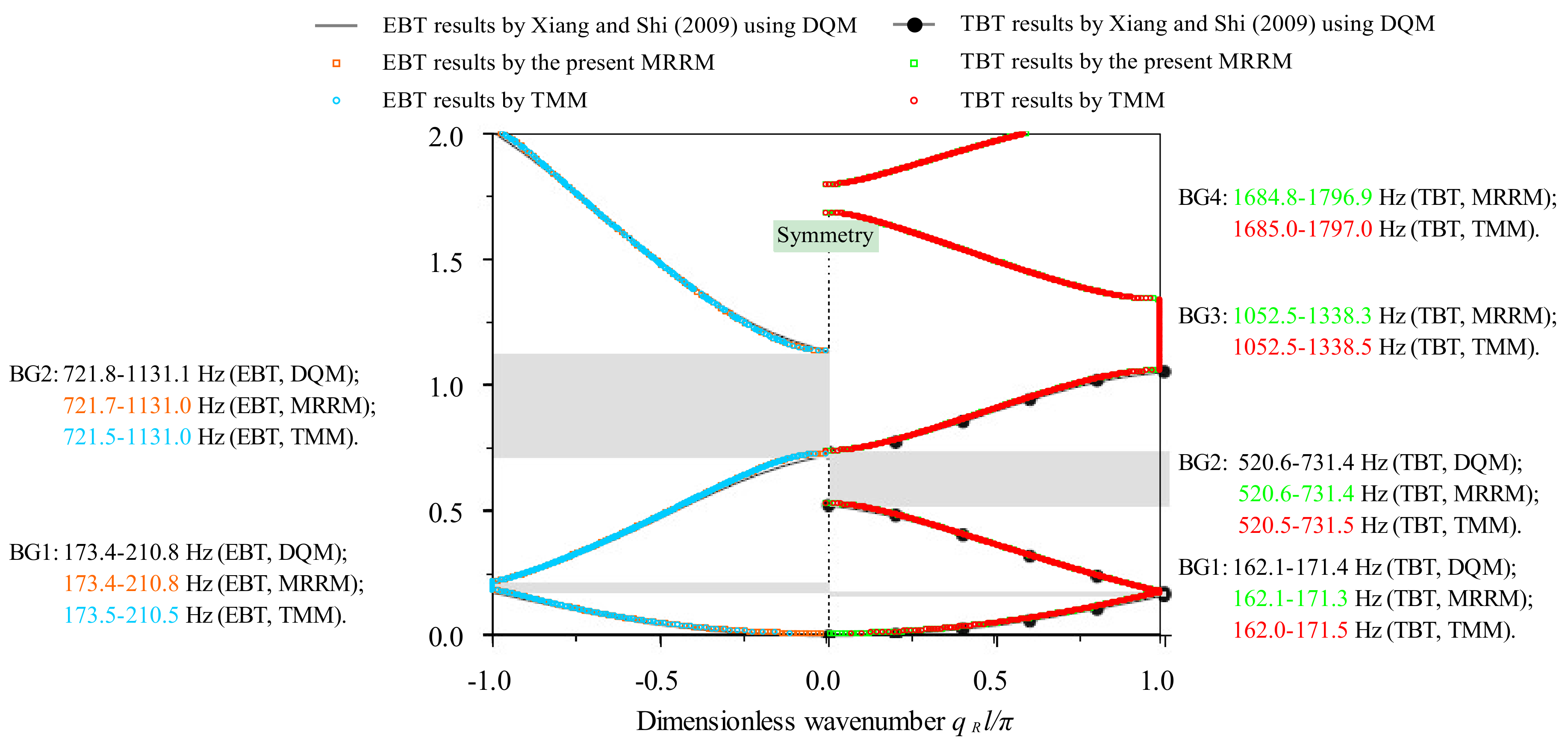
Figure 4.
Comparison of the band structures obtained by the method of reverberation-ray matrix (MRRM) and transfer matrix method (TMM) for a bi-coupled periodic beam consisting of one Binary-II as the unit cell.
Figure 4.
Comparison of the band structures obtained by the method of reverberation-ray matrix (MRRM) and transfer matrix method (TMM) for a bi-coupled periodic beam consisting of one Binary-II as the unit cell.
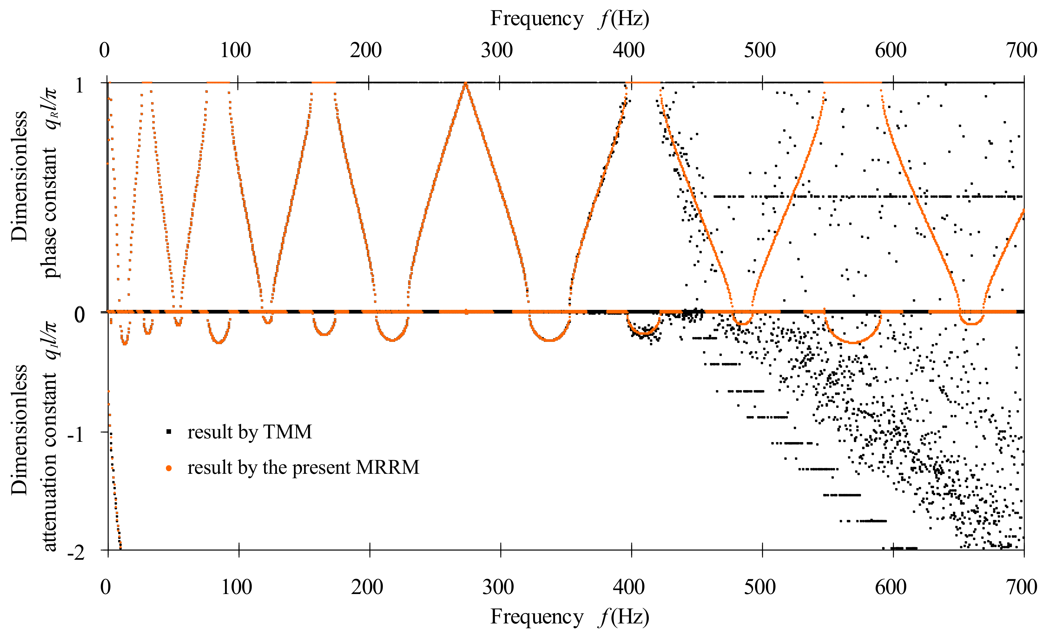
Figure 5.
Comparison of the band structures obtained by MRRM and TMM for bi-coupled periodic beam consisting of three Binary-IIs as the super cell. (MRRM: Method of reverberation-ray matrix; TMM: Transfer matrix method.)
Figure 5.
Comparison of the band structures obtained by MRRM and TMM for bi-coupled periodic beam consisting of three Binary-IIs as the super cell. (MRRM: Method of reverberation-ray matrix; TMM: Transfer matrix method.)
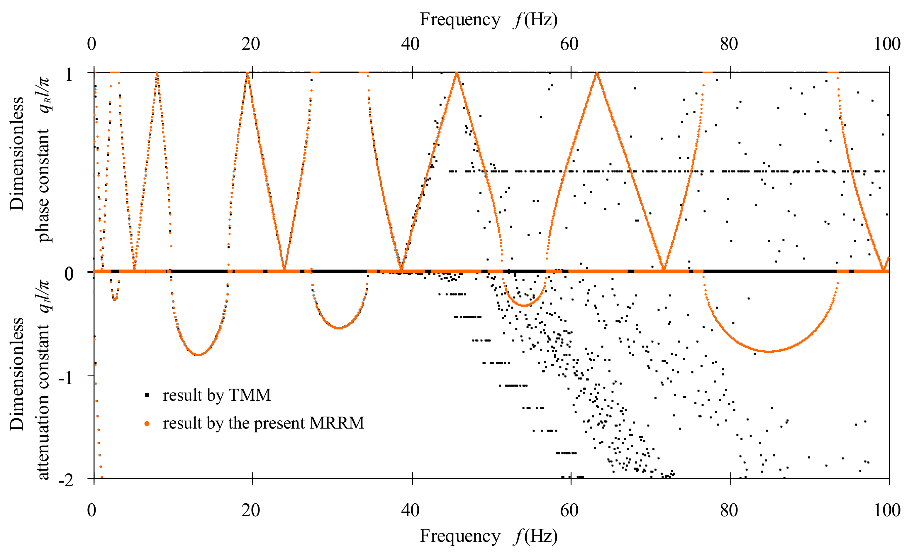
Figure 6.
Frequency-related dispersion curves of bending waves in the bi-coupled periodic beam with Ternary-I unit cell: (a) the attenuation constant spectra; (b) the phase constant spectra; (c) the wavelength spectra; (d) the phase velocity spectra.
Figure 6.
Frequency-related dispersion curves of bending waves in the bi-coupled periodic beam with Ternary-I unit cell: (a) the attenuation constant spectra; (b) the phase constant spectra; (c) the wavelength spectra; (d) the phase velocity spectra.
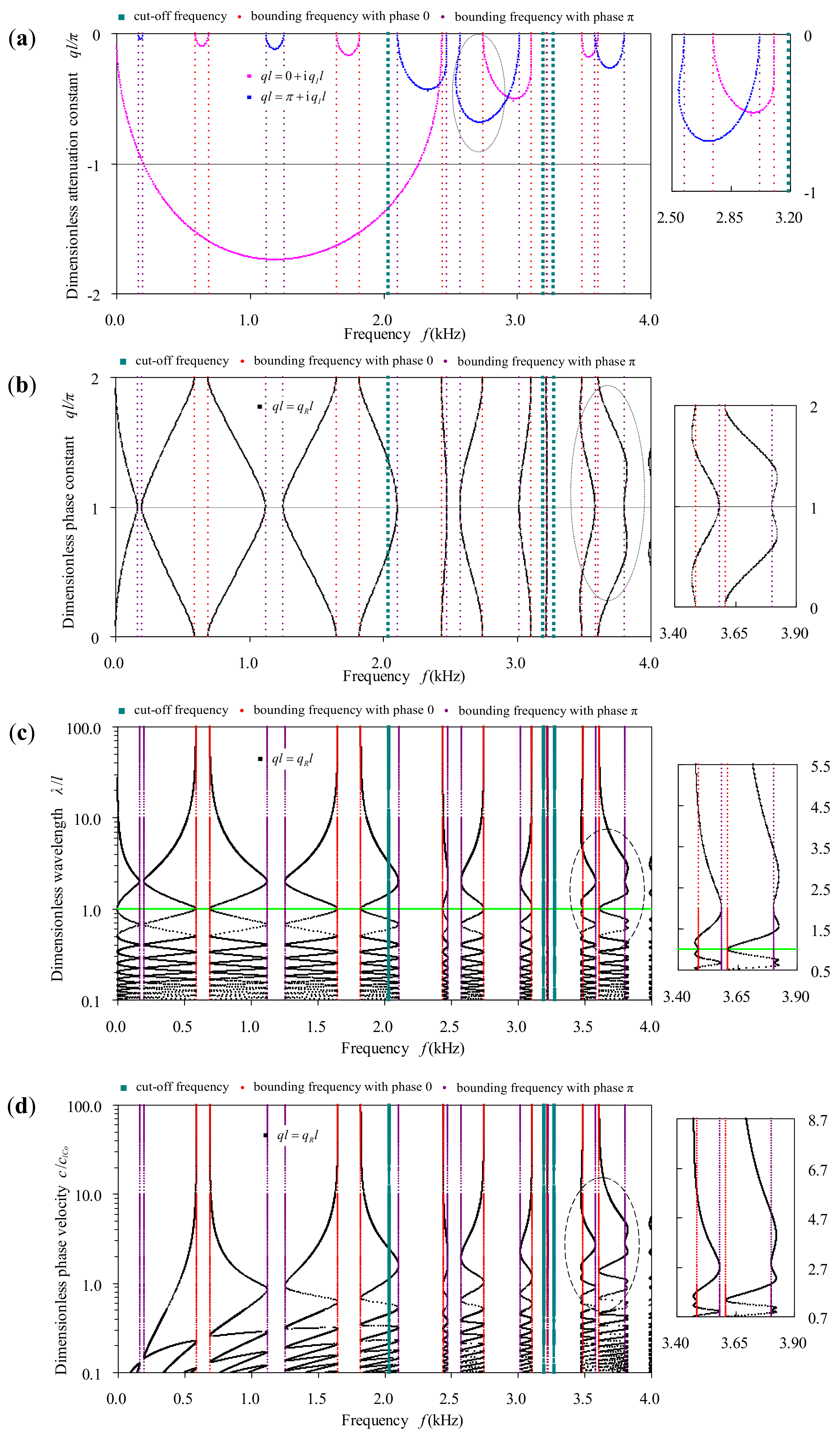
Figure 7.
Phase velocity-related dispersion curves of bending waves in the bi-coupled periodic beam with Ternary-I unit cell: (a) the phase velocity-wavenumber curves; (b) the phase velocity-wavelength curves; (c) the phase velocity-frequency curves.
Figure 7.
Phase velocity-related dispersion curves of bending waves in the bi-coupled periodic beam with Ternary-I unit cell: (a) the phase velocity-wavenumber curves; (b) the phase velocity-wavelength curves; (c) the phase velocity-frequency curves.

Figure 8.
Frequency-related dispersion curves of bending waves in the bi-coupled periodic beam with Ternary-I unit cell within frequency range 500–505 kHz: (a) the phase constant and the attenuation constant spectra; (b) the wavelength spectra; (c) the phase velocity spectra.
Figure 8.
Frequency-related dispersion curves of bending waves in the bi-coupled periodic beam with Ternary-I unit cell within frequency range 500–505 kHz: (a) the phase constant and the attenuation constant spectra; (b) the wavelength spectra; (c) the phase velocity spectra.

Figure 9.
Effect of the cross-sectional area of constituent beam on the band structures of the bi-coupled periodic beam with Ternary-I unit cell.
Figure 9.
Effect of the cross-sectional area of constituent beam on the band structures of the bi-coupled periodic beam with Ternary-I unit cell.

Figure 10.
Effect of the inertia moment of constituent beam on the band structures of the bi-coupled periodic beam with Ternary-I unit cell.
Figure 10.
Effect of the inertia moment of constituent beam on the band structures of the bi-coupled periodic beam with Ternary-I unit cell.

Figure 11.
Effect of the modulus of constituent beam as its Poisson’s ratio remains on the band structures in the bi-coupled periodic beam with Ternary-I unit cell.
Figure 11.
Effect of the modulus of constituent beam as its Poisson’s ratio remains on the band structures in the bi-coupled periodic beam with Ternary-I unit cell.
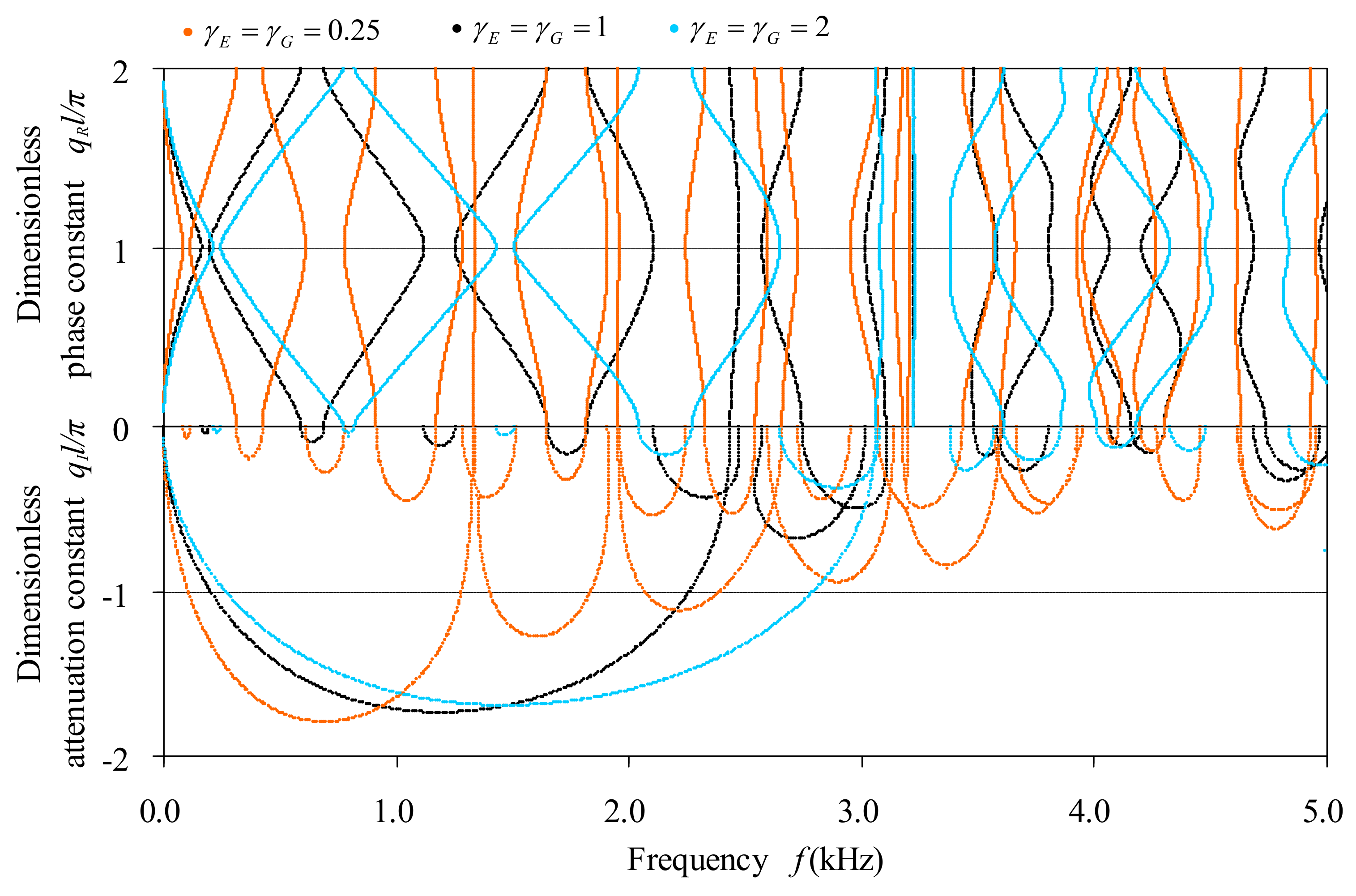
Figure 12.
Effect of the Poisson’s ratio of constituent beam as its Young’s modulus remains on the band structures in the bi-coupled periodic beam with Ternary-I unit cell.
Figure 12.
Effect of the Poisson’s ratio of constituent beam as its Young’s modulus remains on the band structures in the bi-coupled periodic beam with Ternary-I unit cell.
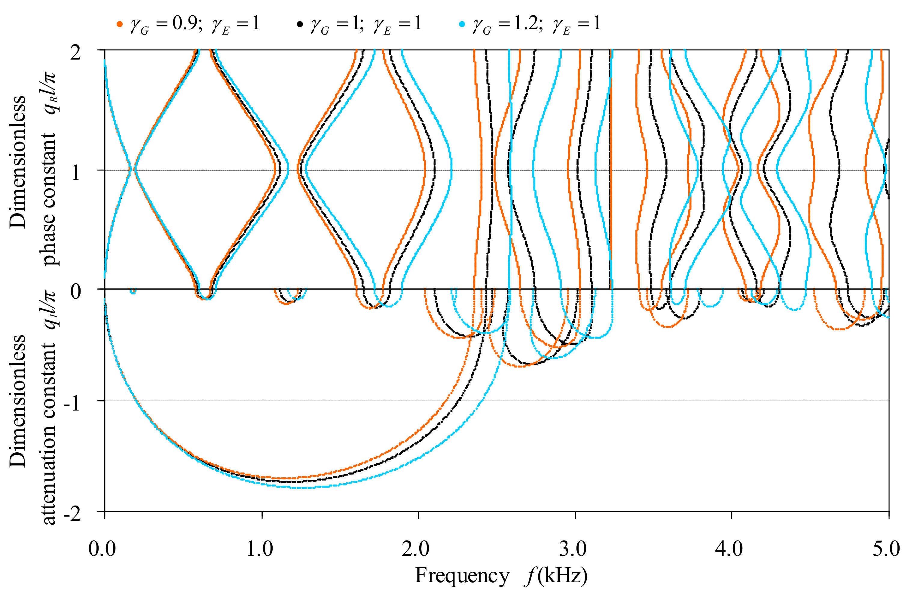
Figure 13.
Effect of the mass density of constituent beam on the band structures in the bi-coupled periodic beam with Ternary-I unit cell.
Figure 13.
Effect of the mass density of constituent beam on the band structures in the bi-coupled periodic beam with Ternary-I unit cell.

Figure 14.
The contrast of the first 10 pass-bands properties for the five exemplified bi-coupled periodic multi-component beams. (a) the central frequencies; (b) the frequency bandwidths.
Figure 14.
The contrast of the first 10 pass-bands properties for the five exemplified bi-coupled periodic multi-component beams. (a) the central frequencies; (b) the frequency bandwidths.


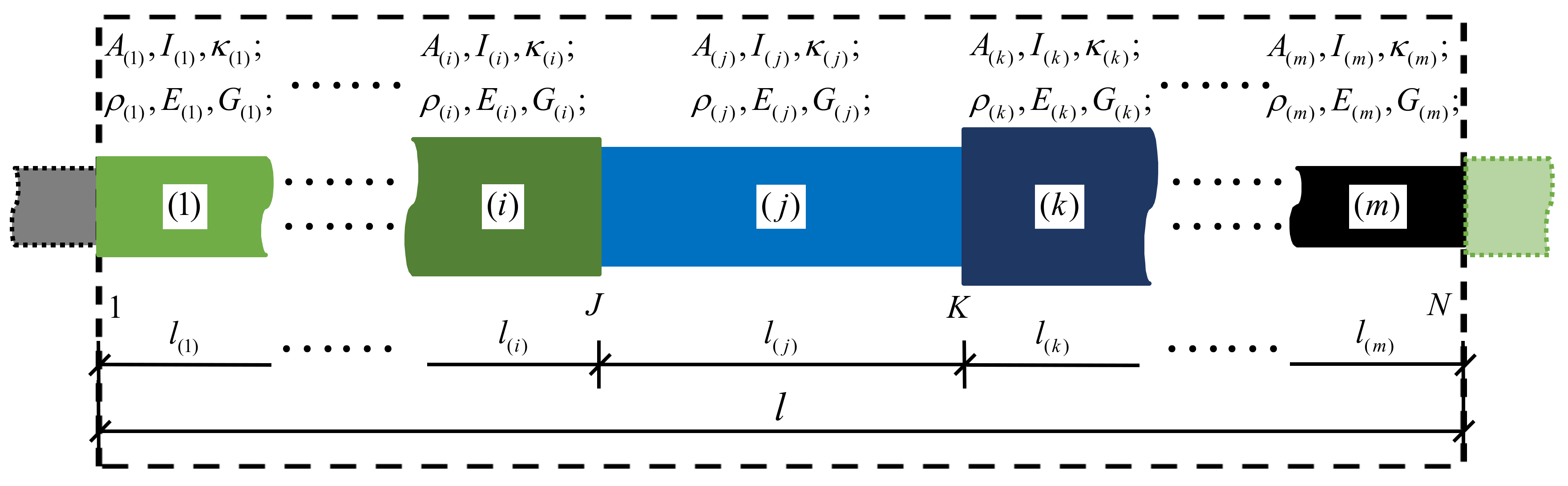
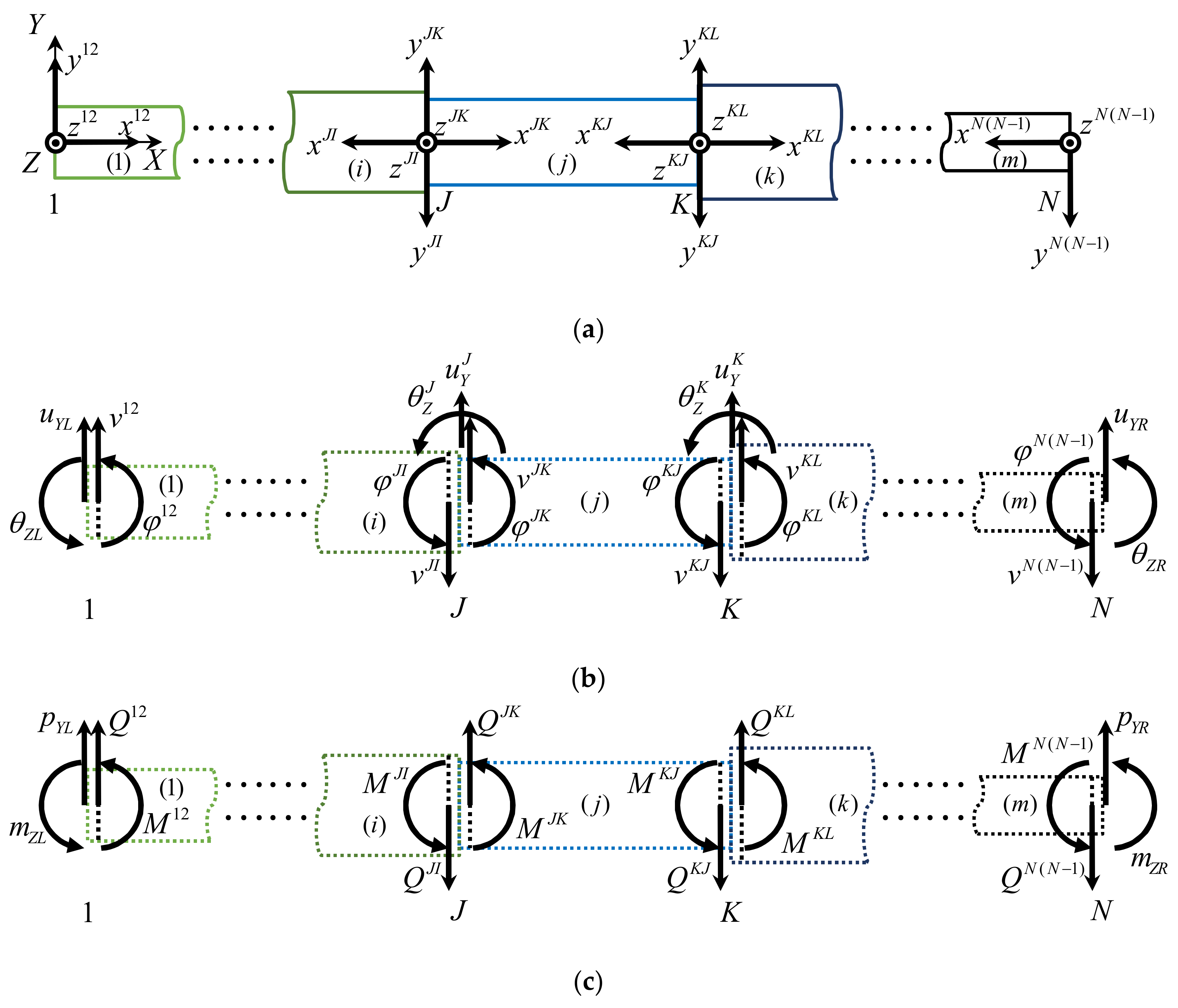
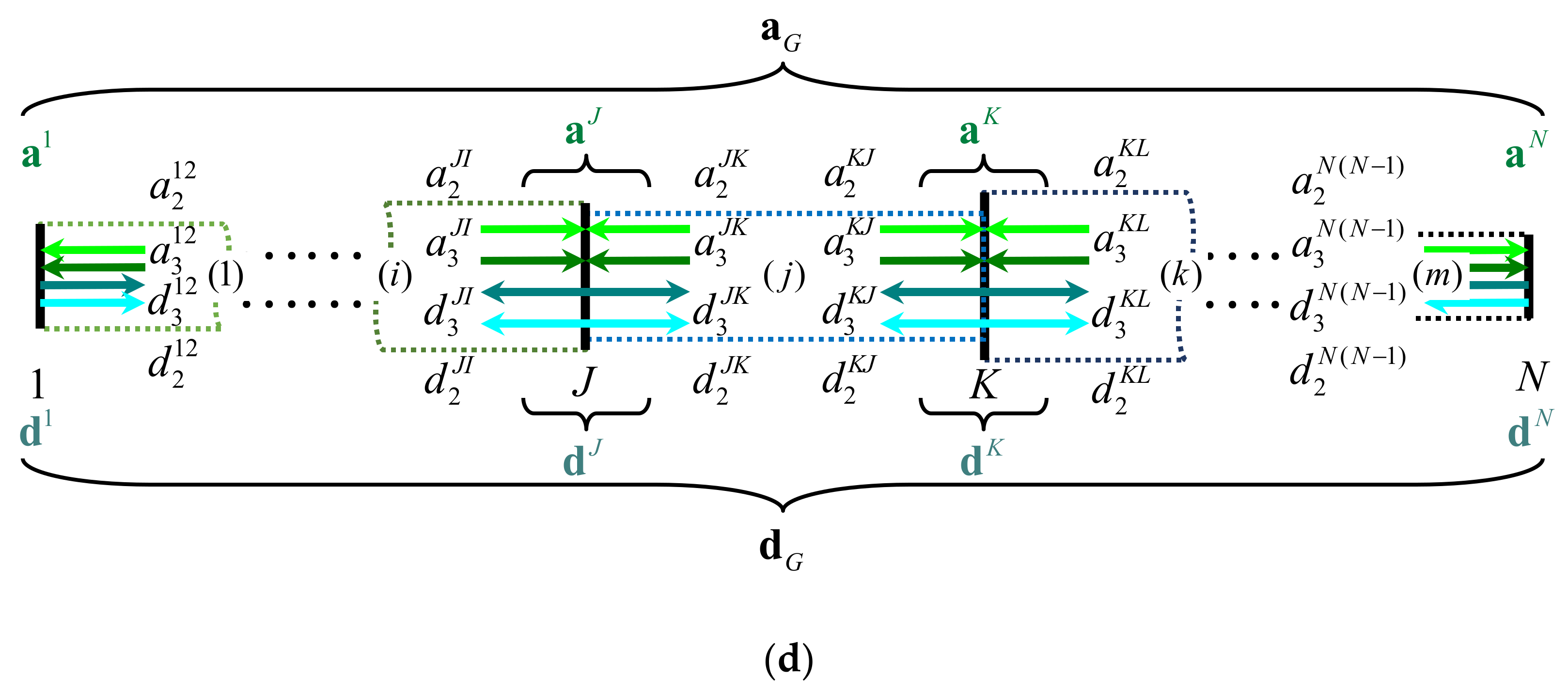
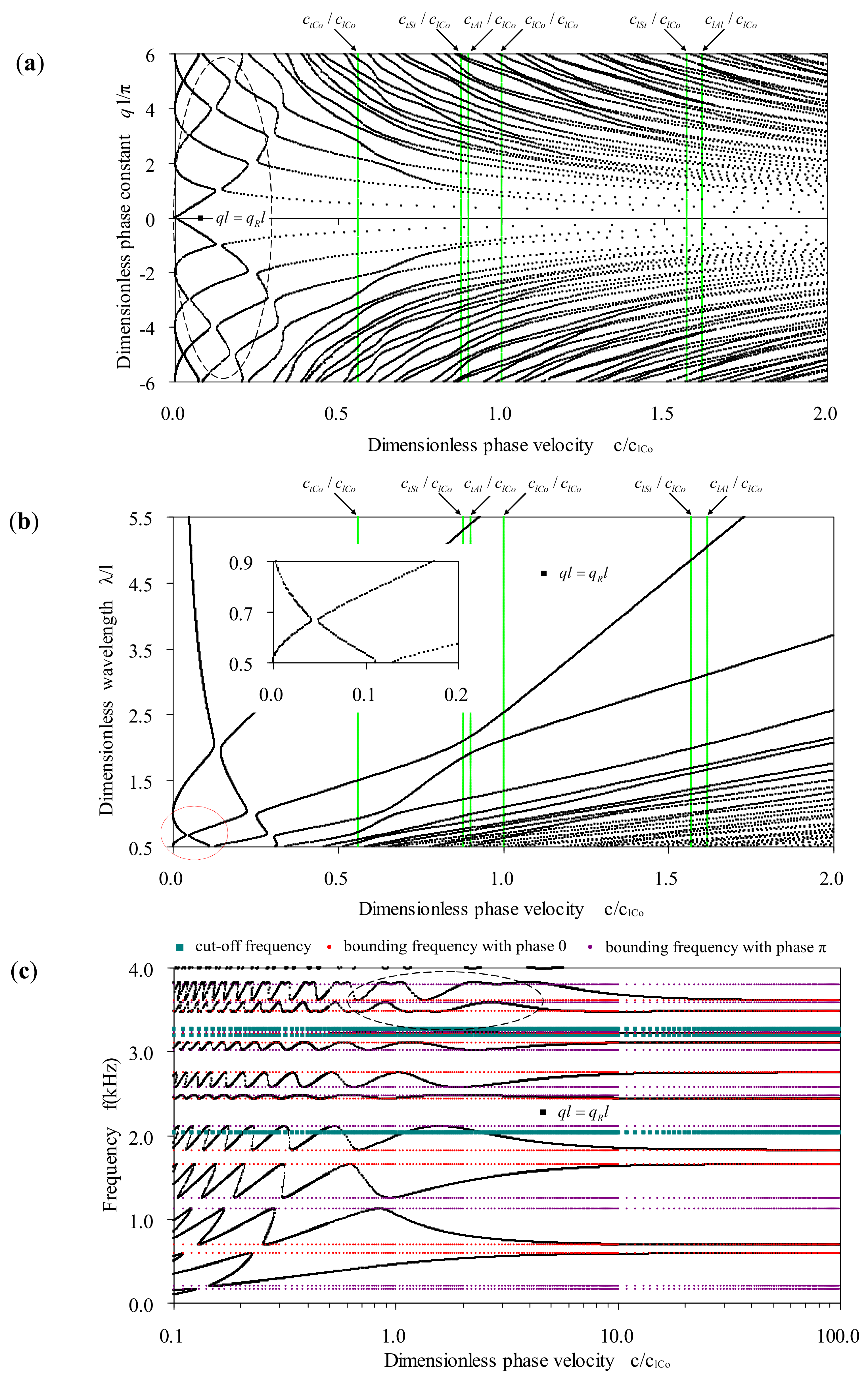
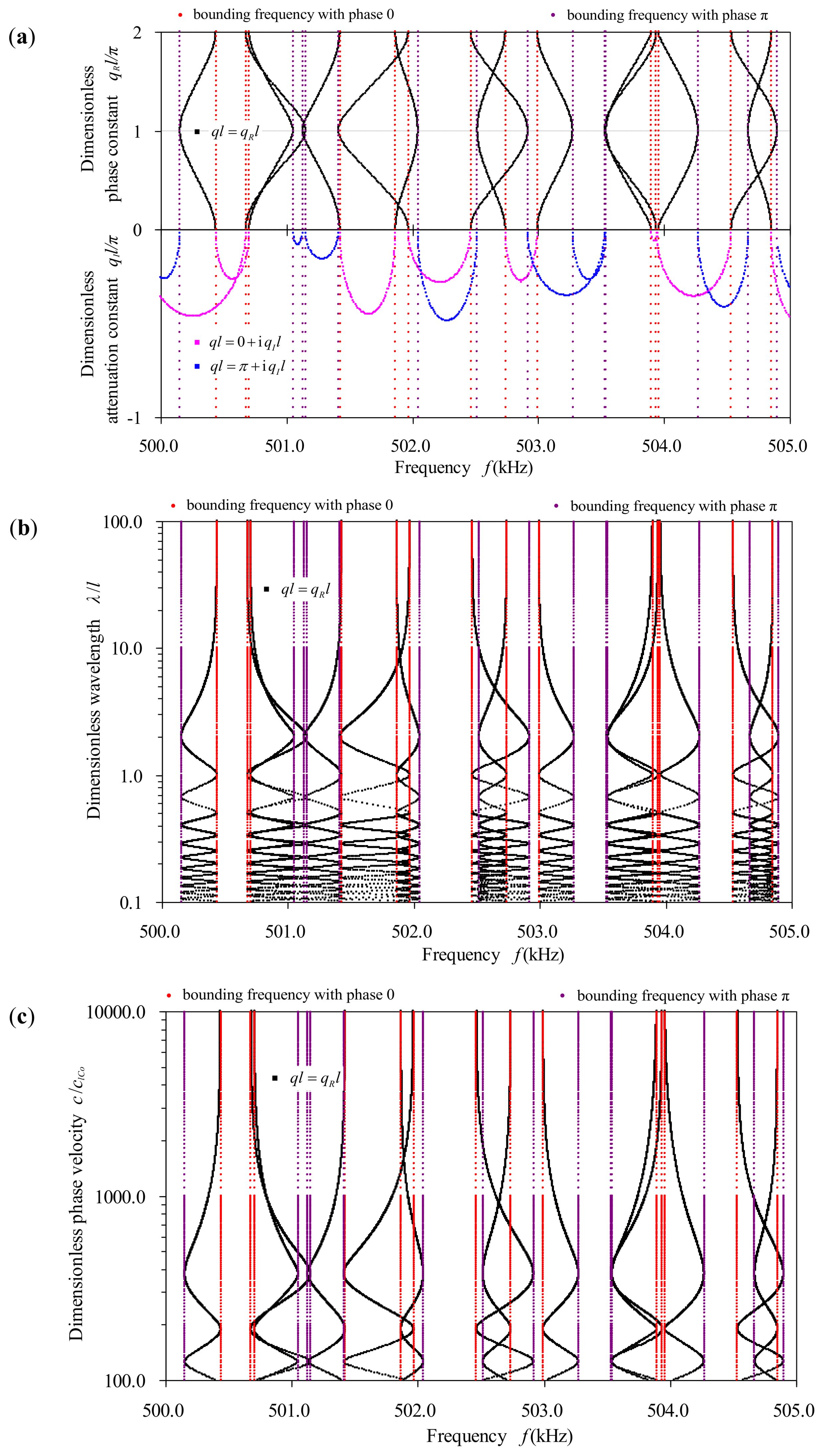
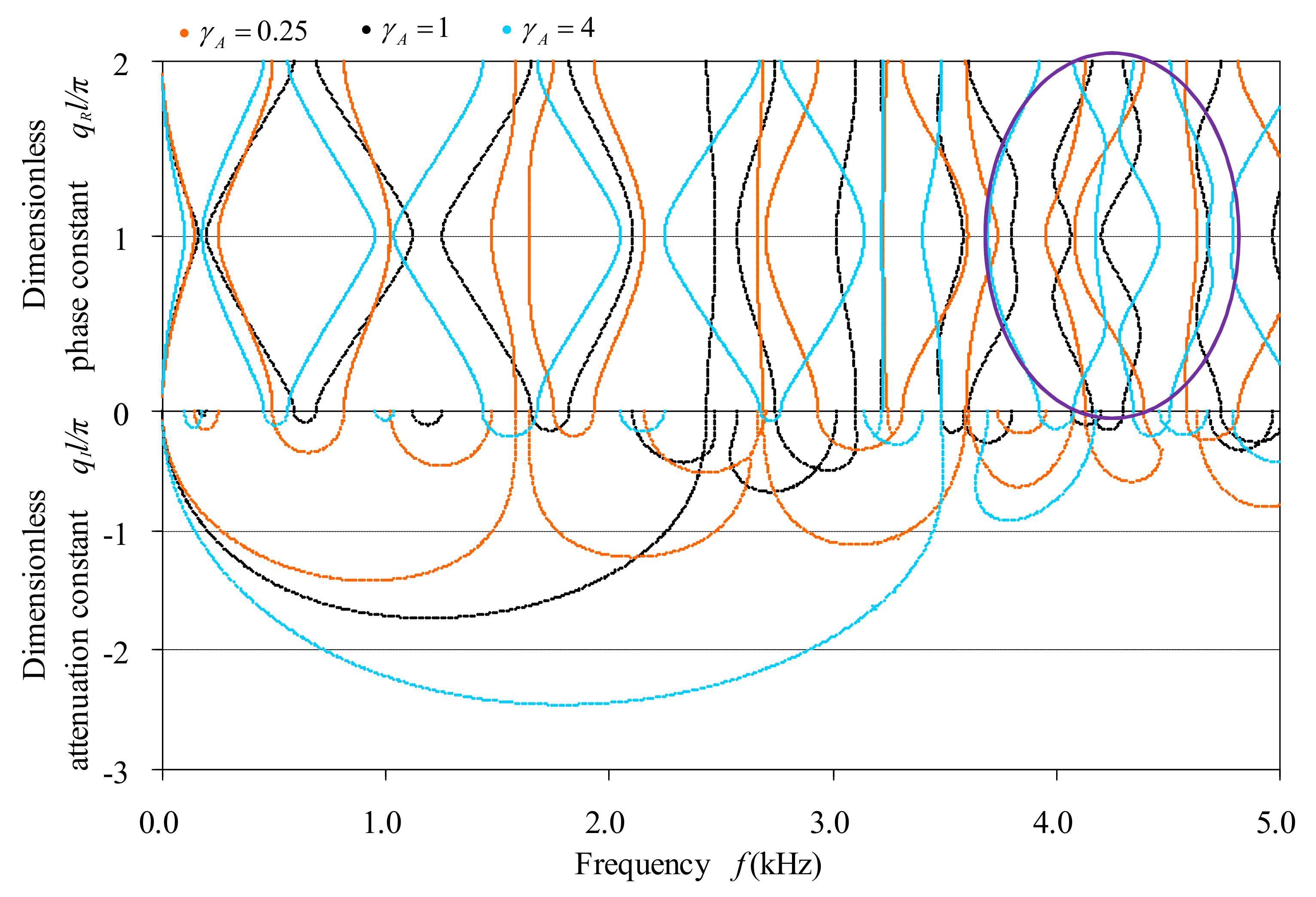
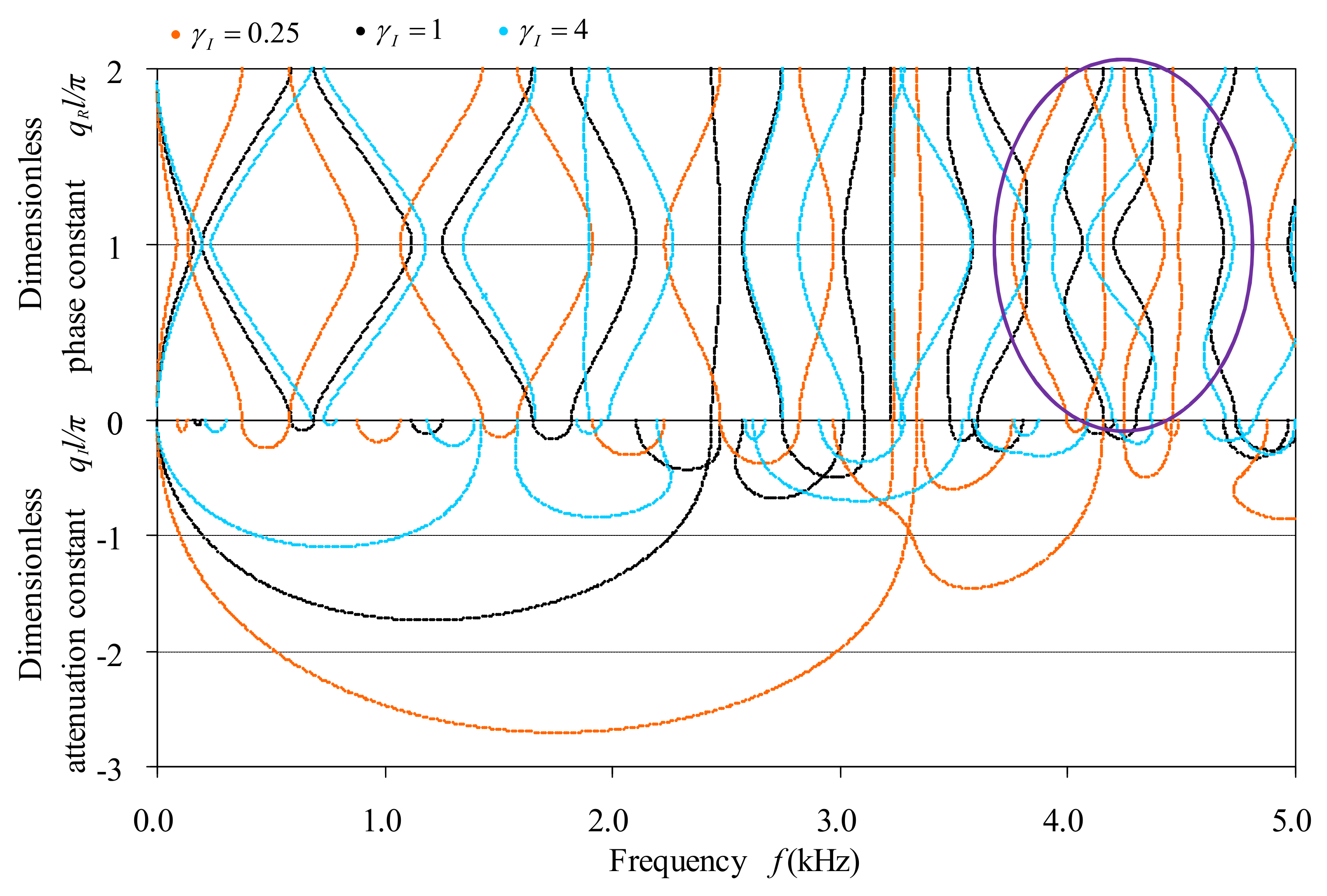
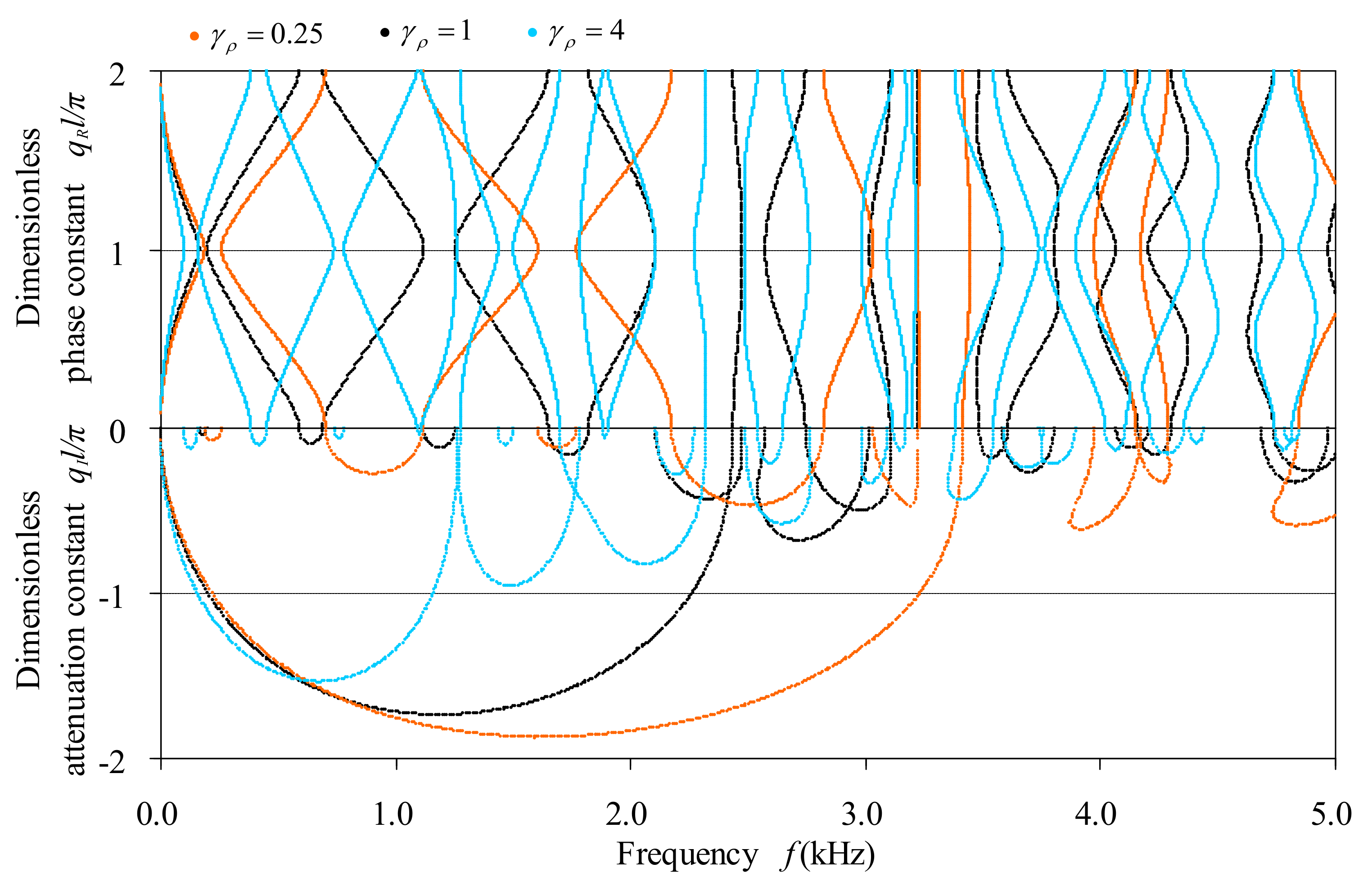
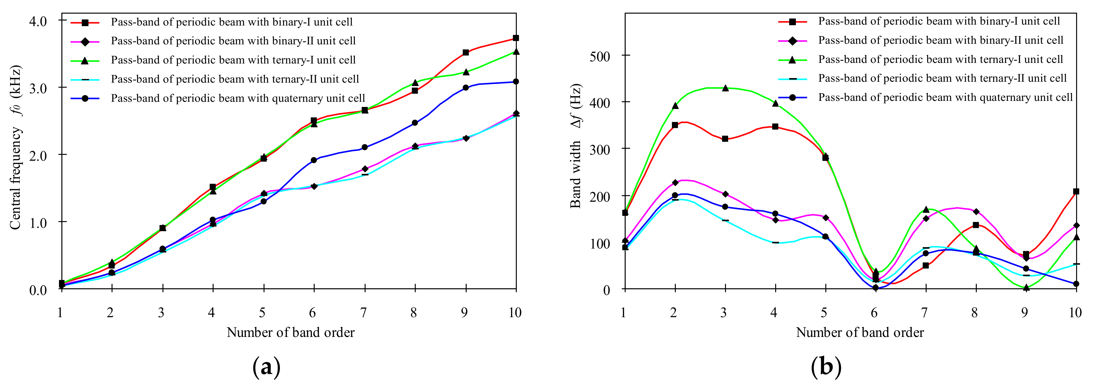
Table 1.
The configuration of five kinds of unit cell in our exemplified bi-coupled periodic beams.
| Unit Cell Type | Configuration of the Unit Cell |
|---|---|
| Binary-I | 1.0 m Concrete beam + 1.0 m Steel beam |
| Binary-II | 1.0 m Aluminum beam + 1.0 m Epoxy beam |
| Ternary-I | 0.5 m Aluminum beam + 1.0 m Concrete beam + 0.5 m Steel beam |
| Ternary-II | 0.5 m Aluminum beam + 1.0 m Epoxy beam + 0.5 m Steel beam |
| Quaternary | 0.5 m Aluminum beam + 0.5 m Concrete beam + 0.5 m Steel beam + 0.5 m Epoxy beam |
Table 2.
The material constants of the four materials involved.
| Material | Young’s Modulus E (GPa) | Shear Modulus G (GPa) | Mass Density ρ (kg·m−3) |
|---|---|---|---|
| Concrete | 25 | 9.40 | 2300 |
| Steel | 210 | 78.95 | 7850 |
| Aluminum | 77.56 | 28.87 | 2730 |
| Epoxy | 4.35 | 1.59 | 1180 |
Table 3.
The bounding frequencies of the first 10 pass-bands of bending waves in the five exemplified bi-coupled periodic multi-component beams.
Table 3.
The bounding frequencies of the first 10 pass-bands of bending waves in the five exemplified bi-coupled periodic multi-component beams.
| Pass-Bands | Periodic Binary Beams | Periodic Ternary Beams | Periodic Quaternary Beam | |||
|---|---|---|---|---|---|---|
| Order | Bounding Frequencies (Hz) | Binary-I | Binary-II | Ternary-I | Ternary-II | Quaternary |
| First | Lower | 0.00 | 0.00 | 0.00 | 0.00 | 0.00 |
| Upper | 162.13 | 102.88 | 165.24 | 83.63 | 88.54 | |
| Second | Lower | 171.35 | 126.66 | 196.46 | 107.72 | 141.59 |
| Upper | 520.61 | 353.47 | 589.39 | 296.93 | 340.82 | |
| Third | Lower | 731.37 | 484.77 | 690.65 | 472.36 | 497.86 |
| Upper | 1052.51 | 686.77 | 1120.80 | 617.87 | 673.13 | |
| Fourth | Lower | 1338.31 | 893.94 | 1253.65 | 885.74 | 937.24 |
| Upper | 1684.79 | 1040.70 | 1650.56 | 984.39 | 1096.64 | |
| Fifth | Lower | 1796.83 | 1348.76 | 1822.11 | 1335.82 | 1238.31 |
| Upper | 2075.91 | 1500.30 | 2105.90 | 1443.82 | 1349.03 | |
| Sixth | Lower | 2479.84 | 1515.88 | 2437.78 | 1525.62 | 1909.45 |
| Upper | 2506.23 | 1535.84 | 2475.43 | 1541.03 | 1910.74 | |
| Seventh | Lower | 2638.36 | 1713.27 | 2574.76 | 1648.44 | 2063.38 |
| Upper | 2687.30 | 1863.85 | 2745.19 | 1735.87 | 2139.10 | |
| Eighth | Lower | 2869.99 | 2038.70 | 3018.43 | 2038.54 | 2422.14 |
| Upper | 3005.43 | 2203.39 | 3105.16 | 2110.07 | 2498.37 | |
| Ninth | Lower | 3468.91 | 2203.39 | 3221.10 | 2234.20 | 2968.38 |
| Upper | 3542.20 | 2268.12 | 3224.44 | 2262.24 | 3010.78 | |
| Tenth | Lower | 3622.93 | 2540.88 | 3473.08 | 2545.36 | 3068.38 |
| Upper | 3830.39 | 2677.25 | 3584.17 | 2597.76 | 3077.64 | |
© 2018 by the authors. Licensee MDPI, Basel, Switzerland. This article is an open access article distributed under the terms and conditions of the Creative Commons Attribution (CC BY) license (http://creativecommons.org/licenses/by/4.0/).
Share and Cite
MDPI and ACS Style
Guo, Y.; Guo, L.; Guo, Z. Reverberation-Ray Matrix Analysis and Interpretation of Bending Waves in Bi-Coupled Periodic Multi-Component Beams. Appl. Sci. 2018, 8, 531. https://doi.org/10.3390/app8040531
AMA Style
Guo Y, Guo L, Guo Z. Reverberation-Ray Matrix Analysis and Interpretation of Bending Waves in Bi-Coupled Periodic Multi-Component Beams. Applied Sciences. 2018; 8(4):531. https://doi.org/10.3390/app8040531
Chicago/Turabian StyleGuo, Yongqiang, Liangteng Guo, and Zhe Guo. 2018. "Reverberation-Ray Matrix Analysis and Interpretation of Bending Waves in Bi-Coupled Periodic Multi-Component Beams" Applied Sciences 8, no. 4: 531. https://doi.org/10.3390/app8040531
Note that from the first issue of 2016, this journal uses article numbers instead of page numbers. See further details here.