Aerodynamic Analysis and Noise-Reducing Design of an Outside Rear View Mirror

1
Electric Powertrain R&D Center, Korea Automotive Technology Institute, 201 Gwahakseo-ro, Guji-myon, Dalseong-gum, Daegu 43011, Korea
2
Department of Mechanical Engineering, Sogang University, 35 Baekbeom-ro, Mapo-gu, Seoul 04107, Korea
*
Author to whom correspondence should be addressed.
Appl. Sci. 2018, 8(4), 519; https://doi.org/10.3390/app8040519
Submission received: 18 February 2018
/
Revised: 16 March 2018
/
Accepted: 23 March 2018
/
Published: 29 March 2018
(This article belongs to the Section Mechanical Engineering)
Abstract
:The outside rear view mirror (OSRVM) is installed on the exterior of vehicles to secure the side and rear views of the vehicle, but its extruded design causes unwanted aerodynamic noise and vibration during driving. In this study, additional line holes (inner dents) are made on the inner and outer edges of the mirror housing without a reduction in size in order to enhance the aerodynamic flow and noise around the mirror. Based on computational fluid dynamics (CFD) analysis, this study compares the aerodynamic characteristics of the original and modified mirror models. The comparative analyses verify that the proposed OSRVM model with the inner ducts dramatically improves the velocity profiles and sound pressure levels.
1. Introduction
Since noise, vibration and harshness (NVH) are now significant in passenger vehicles, automotive industries are interested in levels of NVH as a component of the development of comfortable vehicles. In particular, aerodynamic sound is the predominant component of interior vehicle noise at speeds above 100 kph [1]. Various design technologies have been developed in order to reduce the aerodynamic noises induced by high-speed driving.
The design modification of the mechanical components interacting with airflow is needed for the reduction of aerodynamic noise. The outside rear view (or side view) mirror (OSRVM) is installed on the exterior of vehicles to help the driver see the areas behind and to the sides of the vehicle. During driving, the bluff body of the mirror interacts with high-speed airflow, causing flow separation, recirculation, and an irregular vortex. The protruding mirror generates strong pressure fluctuation on the door panels and windows, and the unsteady air pressure then propagates into the vehicle interior as noise [2]. In general, the side view mirror is also known to increase the total amount of drag by 2~7% [3].
Reports from recent decades indicate that the OSVRM generates intrinsic acoustic noise. Lounsberry et al. has reported that a whistle-like mirror noise radiates from the mirror housing. They showed that when the transition to a turbulent boundary layer over the housing of the mirror was not complete, pressure fluctuations near the trailing edges of the mirror housing rapidly changed flow patterns, resulting in the whistle noise [3]. Other researchers also demonstrated that whistle noise is attributed to the considerable change in the A-pillar vortex and increase in turbulent intensity [4,5].
Kim et al. has studied the velocity vector fields of the wake and pressure distribution over the mirror skin in order to investigate the wake structure and the vortex body frame interaction near the OSRVM. They measured the surface of the mirror by use of hot-wire anemometry and the pressure scanning system [6,7]. Ask et al. has investigated the flow field and the acoustic sources of the OSRVM by evaluating different advection schemes, turbulence models, and three levels of grid resolution. The paper showed that a match between the measured and computed results is found using several static pressure sensors located at the OSRVM [8]. Moreover, various experimental and simulation studies have been investigated to identify aeroacoustics sources and noise generation of the side mirror [9,10,11,12,13].
A design modification of the protruding mirror is needed in order to reduce the aerodynamic noise. Some typical strategies have been observed to reduce the traditional problems of the side mirror, such as noise and mirror surface vibration. The earlier studies have suggested aerodynamic optimization techniques in order to reduce the strength of the intrinsic shedding vortex and suppress the generation of aerodynamic noise by changing the geometric shape of the mirror, such as its bracket height, the housing height and size, the bezel shape, the elimination of sharp edges on all of the corners, and the tube-type extension of the mirror housing [2,3,10]. However, there are limitations to reducing the geometry of the side mirror for aerodynamic noise, because it also satisfies the size constraint to secure its visual angle.
Very little study has been undertaken to reduce the aerodynamic sound of the side view mirror with additional dents while keeping its size, although some studies in the aerospace industry have reduced the noise by adding additional devices such as riblets or vortex generators [14,15]. Accordingly, the object of this study is to enhance the aerodynamic flow and sound radiation by adding inner dents on the external shape design of the OSRVM. The commercial program FLUENT was used to analyze the drag coefficient variation according to the shape of the OSRVM. Based on computational fluid dynamics (CFD) analysis, this study investigates aerodynamic flow characteristics and sound pressure levels at three major points around the mirror housing.
2. Design and Analysis
2.1. 3D Modeling and Geometry of OSRVM
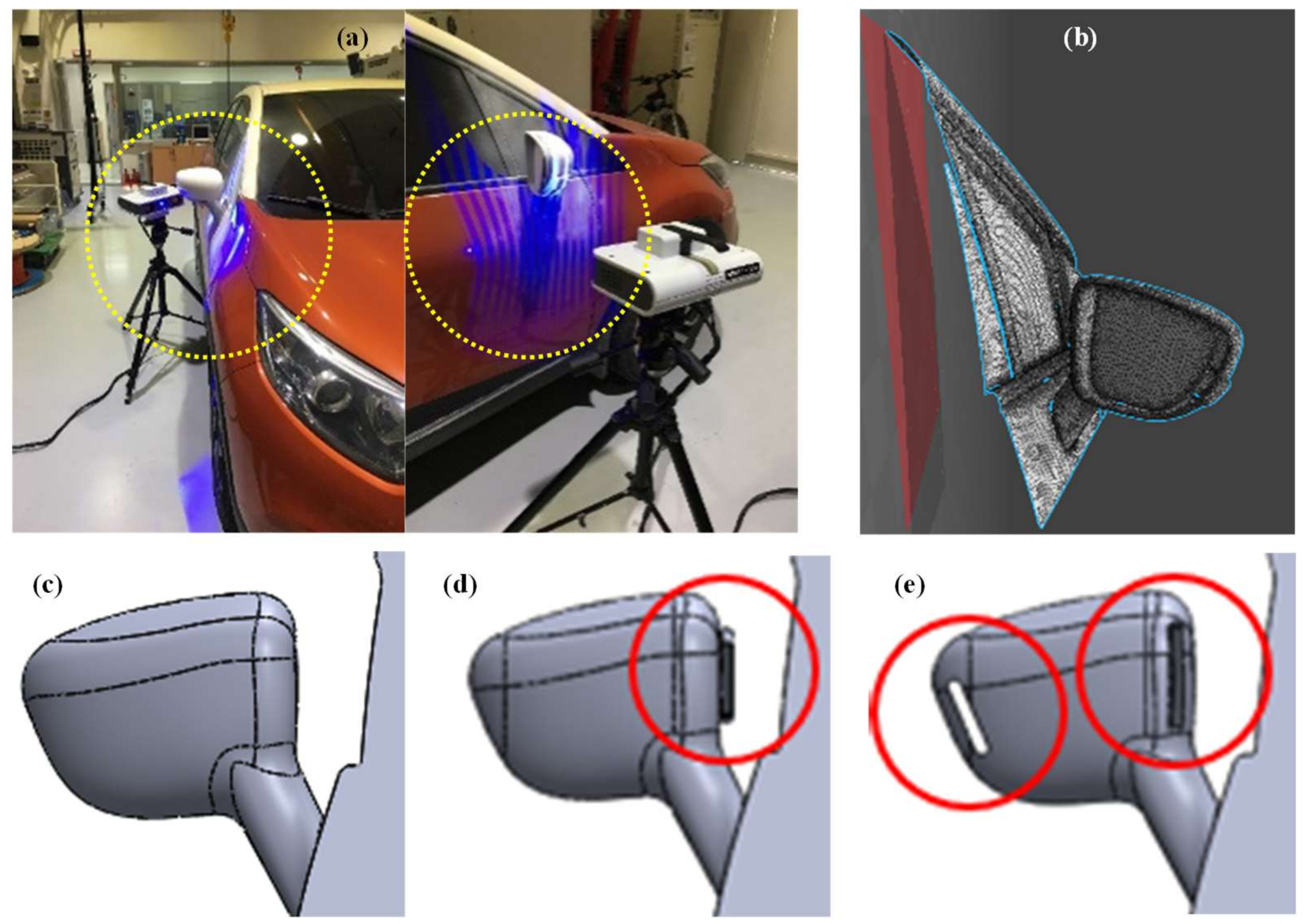
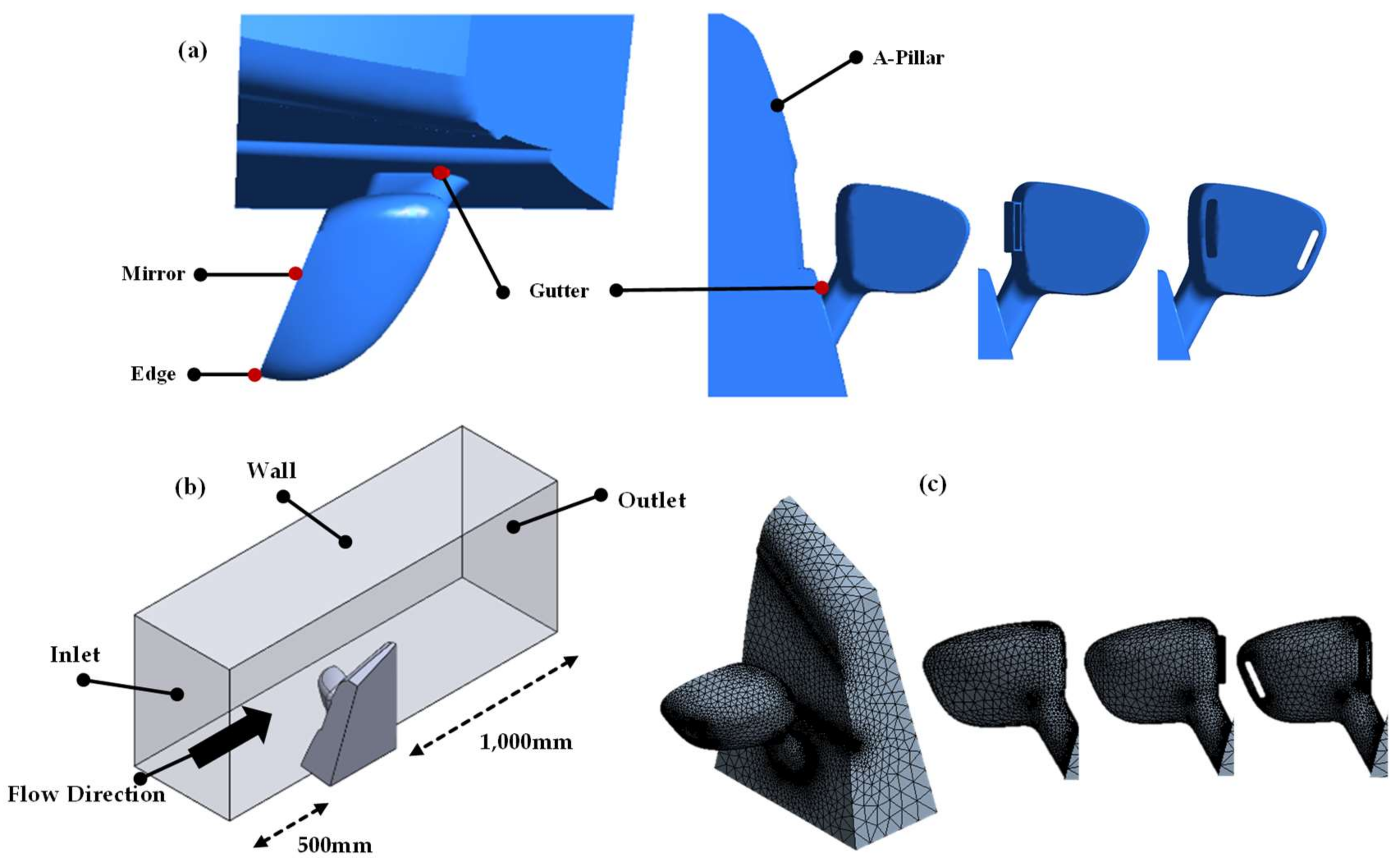
In order to improve the aerodynamic flow around the side mirror, we calculate the aerodynamic noise radiation through a direct solution of commercial CFD code FLUENT. In this study, we consider three types of OSRVM models to compare shape-dependent aerodynamic effects. The first model is the reference mirror, which is obtained by three-dimensional (3D) scanning the OSRVM of the R company (Ussac, France)’s C-segment CUV, as shown in Figure 1a. Figure 1b shows the side mirror geometry extracted from the scanned data of an A-pillar and the side mirror. In addition, the OSRVM was reversed by using a commercial software Geomagic Design X, which is based on the gathering scan data, and the layout shape of the reference OSRVM is shown in Figure 1c.
The second OSRVM model is designed by adding a duct outside the mirror housing, as shown in Figure 1d, which is normally used in commercial vehicles for improving the aerodynamic flow. The duct is located between the OSRVM and the gutter. The last model is designed by inserting two inner ducts (line holes) on the inner and outer edges of the mirror housing, as shown in Figure 1e. Airflow passes from the leading edge to the trailing edge of the mirror housing through the line holes. Since the aerodynamic flow distributes by the inner ducts, airflow rate become stable and reduce the vorticity around edges, gutter, and the mirror surface. Two modified OSRVM models are designed to maintain the continuity of the existing mirror shape without the size reduction of the original mirror.
In this paper, the CFD analysis is performed for the modified mirror models, based on the variation of the drag coefficient or the rate of change of the air contact area. Any vehicles moving through a fluid experience drag force in the direction of flow due to pressure and shear forces acting on the surface of the object. The drag coefficient can be expressed by
Here, is the drag force, is the fluid density, A is the characteristic frontal area of the mirror, and is the flow velocity. The drag coefficient is a function of several parameters, such as the mirror shape and size. In general, it is possible to predict changes in sound pressure levels through the drag force and pressure variations that are applied to the OSRVM’s housing and the surface of the mirror. The gradient of the flow rate, such as velocity and vorticity around the OSRVM, causes the pressure gradient. Then the variations in the pressure gradient affect the aerodynamic performance, allowing for the increase or decrease in aerodynamic radiation noise to be predicted. In addition, for the design considering the aerodynamic performance of the OSRVM, it is necessary to determine the pressure gradient formed around the OSRVM through the CFD solution.
2.2. Boundary Conditions and Analysis
In general, the extruding components in the vehicle exterior such as the OSRVM, a rear wing, a radio antenna and the exterior accessories, cause the aerodynamic noise radiation while driving. In this study, we analyze the aerodynamic flow to generate aerodynamic noise. In the CFD simulation, the aerodynamic performances of the three mirror models are compared by quantifying the flow velocity, the sound pressure levels and the vorticity at three points (the gutter, the edge and the center of the mirror surface) around the OSRVM, as shown in Figure 2a.
A cuboid computational domain was used to obtain the CFD solution in this approach, as illustrated in Figure 2b. It considers airflow rate and field, and the size of the computational domain is 580 mm × 800 mm × 2000 mm. The gutter, which is a small part of the A-pillar, is included in the computational domain to minimize the aerodynamic effect from the surrounding features during driving, since the vehicle body is placed in front of and to the rear of the OSRVM. The gaps on the gutter between the side mirror and A-pillar often provide flow separations. In addition, the mirror was mounted about 1000 mm downstream of the elliptically-shaped leading edge of the side plate, as illustrated in Figure 2b. In general, the main source of aerodynamic noise was the vortex and turbulent flow of the rear side, rather than the front side, of the mirror. Therefore, the computational domain was also set to the rear side of the OSRVM. This computational domain was based on the geometry considered by Olsson [16] and Wang et al. [17], which have studied the aerodynamic experiments of the side mirror and the feasibility of the aerodynamic simulation.
In the simulation, homogeneous velocity was applied at the inlet in the vehicle-driving direction. In addition, homogeneous pressure was applied at the outlet as a boundary condition considering the flow field. A stationary wall (no-slip) condition was applied to the surfaces of the objects and the computational domain. The computational fluid dynamic analysis using FLUENT was conducted using the environmental conditions of the vehicle speed, relative humidity and temperature of the inlet. The environmental conditions summarized in Table 1 are based on Murad et al. [10], where the free stream velocity of 38.9 m/s is equivalent to the vehicle speed of 140 km/h.
The speed regulation of city is 60 km per hour (kph), and the highway’s regulation is from 80 kph to 100 kph. The freeway’s regulation is about 110 kph. Therefore, the vehicle’s speed was grouped by road environment and speed regulation. The reference of temperature was decided by an ordinary temperature between 18 and 25 degrees Celsius. Relative humidity was grouped by weather conditions (clear, wet, and rainy) between 30% and 70%.
In order to identify the aerodynamic noise sources, the steady-state flow analysis was performed to guarantee an appropriate resolution of the vortex structure of the flow field. In general, the Reynolds number is an important parameter for describing the aerodynamic flow. If the Reynolds number increases as the velocity increases, then the transition position moves forward. With an adverse pressure gradient, the turbulent boundary layer keeps the flow attached longer before it separates. Moreover, the standard k-epsilon turbulence model was applied for the steady-state analysis. The k-epsilon model is the simple complete model of turbulence; its computational costs are lower than that of other methods, such as large eddy simulation. The k-epsilon model is a semi-empirical model based on model transport equations for the turbulence kinetic energy and its dissipation rate.
A broadband noise source model was applied for aeroacoustic analysis. Unlike the direct method and the Ffeowcs-Williams & Hawkings (FW-H) integral method, the broadband noise source model does not require transient solutions to any governing equations of fluid dynamics, but it requires the least computational resources [18]. The layout of finite element meshes for the inner duct OSRVM model is shown in Figure 2c. In this study, a hybrid mesh with an outer hex mesh and an inner box surrounding the mirror were generated by the automatic mesh function in the commercial CFD code., Moreover, the sound pressure levels (dB) were analyzed for different cases of temperature, relative humidity and driving speed as shown in Table 1.
3. Simulation Results
3.1. Aerodynamic Simulation of the Reference OSRVM Model
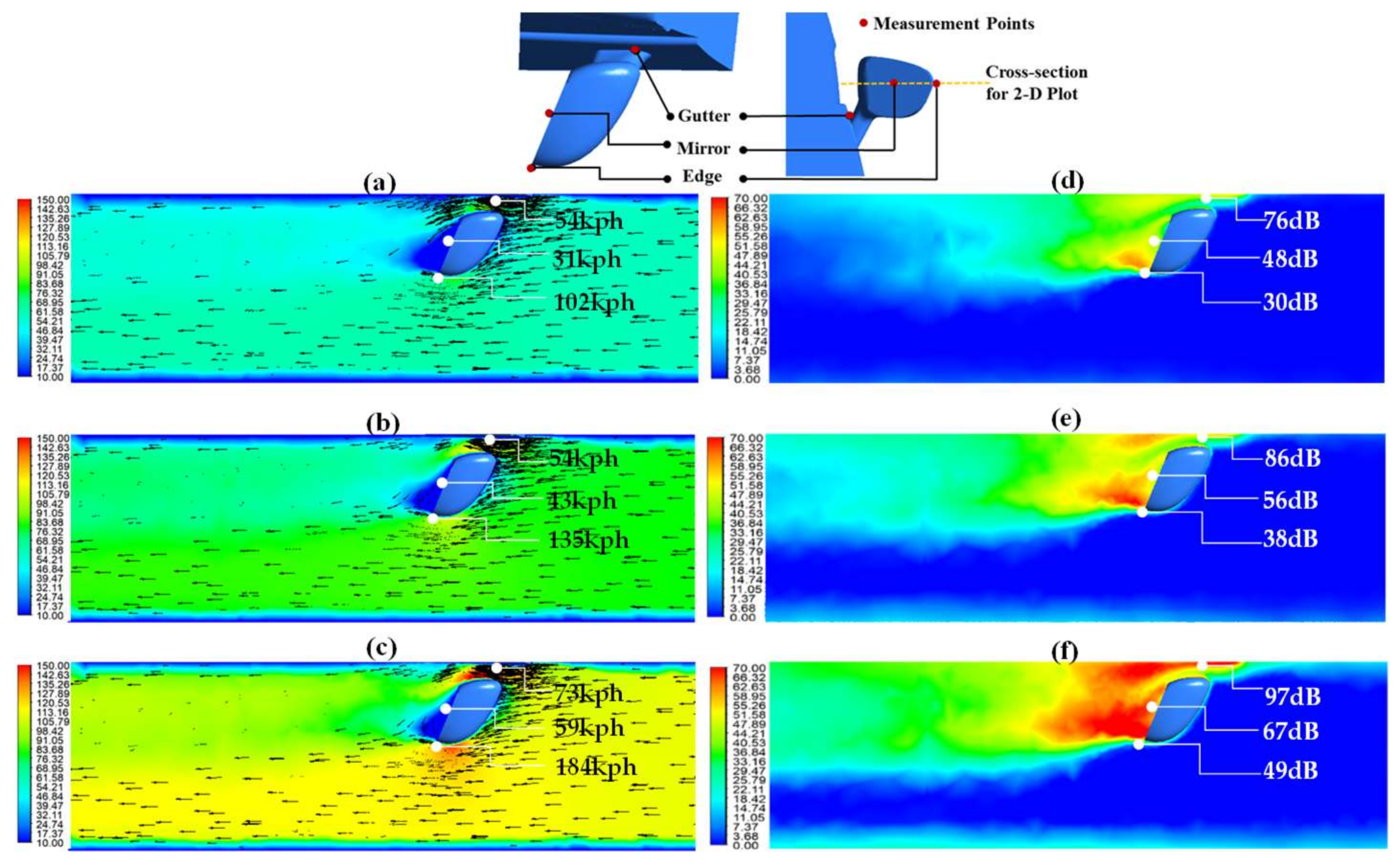
In general, the tonal noise occurs from the interaction of vortices with the gutter and edges of the side mirror. High levels of aerodynamic noises are generated in the gutter and edges during driving. Figure 3a–f show the CFD analysis results of the airflow velocity and the sound pressure levels (dB) around the reference OSRVM for three vehicle speed cases of 60 kph, 80 kph, and 110 kph at 23 °C temperatures and 50% humidity conditions. The value and region of aerodynamic flow rate and sound pressure level rapidly increase while the driving speed changes from 60 kph to 110 kph.
Figure 3a–c show flow the velocity vector and contour in the cross-sectional plane of the reference mirror. The values of flow velocities at the gutter, mirror surface, and outside edge are displayed in the graphs. Vortexes are formed underneath the trailing edge of the mirror, and the gradual decrease of vortex length occurs for increasing speed. Strong vorticity (the curl of the flow velocity) appears at the gutter or behind the trailing edge of the mirror surface when the airflow rotates.
Figure 3d–f shows the aerodynamic sound radiation around the reference side mirror. At higher driving speeds, the sound pressure level dramatically increases at the gutter and the mirror surface. The graphs indicate that the sound pressure level becomes the largest around the gutter at all of the speeds. The noise level at the gutter at the vehicle speed of 110 kph is 97 dB. The aerodynamic noise radiation is mainly due to pressure fluctuations by the changes of the flow velocity and the air density, which are induced from the difference of vorticities around the gutter or the trailing edge of the mirror surface. This result agrees well on previous studies reporting that the intrinsic mirror noise sounds like a whistle, radiating from the pressure fluctuations near the trailing edges of the mirror housing [4] and considerable change in the A-pillar vortex [5]. A higher sound level at the mirror surface compared to that of the outside edge agreed with the previous result [3], which showed that the maximum magnitude of the fluctuating pressure appeared at the central bottom region on the mirror surface.
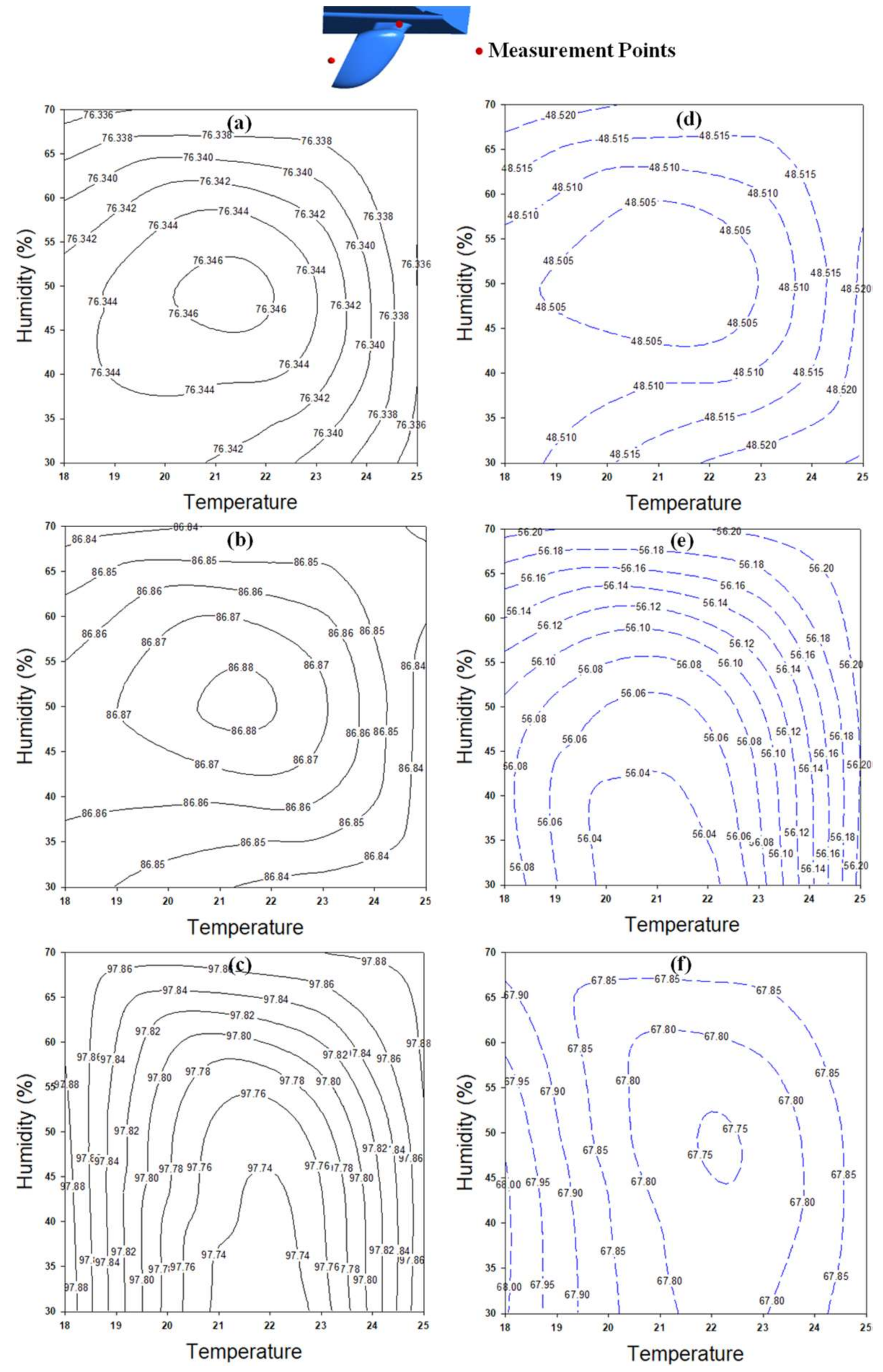
In order to investigate the effects of driving speed, temperature, and relative humidity on the sound pressure levels around the mirror, a comparative analysis was performed for 27 cases using the conditions of Table 1. Figure 4 shows the graph charts of the sound pressure levels of the reference OSRVM model for various cases. Figure 4a–c are measured at the gutter, and Figure 4d–f are measured at the surface of the mirror. These results indicate that the sound pressure level of the reference OSRVM is mainly affected by vehicle velocity, but relatively less changed by temperature or relative humidity variation.
3.2. Analysis of the Second Model with Outer Duct
The second OSRVM model has an additional duct outside the mirror housing in the direction of the A-pillar, as shown in Figure 1d. In general, the main role of the outer ducts is to guide airflow via external or internal obstacles in mechanical devices such as the heat pump and braking system. This extruded duct is sometimes used in commercial vehicles for improving the aerodynamic flow.
Figure 5a–c shows the wind velocity of the second OSRVM model for three speed cases of 60 kph, 80 kph, and 110 kph at 23 °C temperature and 50% humidity conditions. The airflow velocity increases around the gutter and edge compared to the reference model. Especially, the airflow velocity dramatically increases at the edge to 214 kph at the vehicle speed of 110 kph. The low-velocity region (blue-colored area) behind the trailing edge of the mirror, where cavitation occurs, becomes larger than that of the reference model. However, this leads to a high vorticity difference between the gutter (or edge) and the mirror, keeping turbulence tails behind the mirror and flow separation at the trailing edge. Moreover, the flow separation becomes strong at the gutter between the A-pillar and the mirror by dense velocity vectors.
Figure 5d–f shows the sound pressure levels of the outer duct model for the three driving speeds. Aerodynamic noise radiation rapidly increases around the gutter, and it has the maximum value (261 dB), even at the low speed (60 kph). In this model, the magnitude of aerodynamic noise grows as the driving speed increases to 110 kph at the mirror surface and the edge. This dramatic increase of aerodynamic noise radiation of the outer duct model is due to high pressure fluctuation at the gutter. Meanwhile, the short vortex tails and turbulences around the surface of the mirror affect the sound radiation. Moreover, high pressure fluctuation around the mirror housing propagates vibration on the window for high driving speeds.
3.3. Analysis of the Third Model with Inner Duct
The third OSRVM model has two inner ducts (line holes) in the mirror housing in order to improve the aerodynamic flow and noise. The role of the inner ducts is like a brake cooling system. It guides to control the rate of air via an internal airflow pass. Figure 6a–c shows the flow velocity of the third mirror model for the three driving speeds of 60 kph, 80 kph, and 110 kph at 23 °C temperature and 50% humidity conditions. The simulation results show the inner duct model has the lowest flow velocity at all of the points (gutter, mirror surface, and edge). The aerodynamic flow disperses along the internal ducts, so that the maximum flow rate is dramatically reduced around the gutter and the trailing edge of the mirror surface. Moreover, the inner duct model has the shortest vortex tail and flow separation at the trailing edge of the mirror surface among the three OSRVM models.
Figure 6d–f indicates the sound pressure levels (dB) of the inner duct model for the three driving speeds. The aerodynamic noise radiations that were generated around the gutter and the trailing edge of the mirror rapidly decreased. The magnitude of aerodynamic noise grew rapidly as the driving speed increased. For the driving speed of 110 kph, the high sound pressure regions of the gutter and the edge did not cross each other by the additional inside ducts. The behavior of airflow and noise radiation are dramatically improved by the internal ducts on the mirror housing.
3.4. Result Comparisons and Discussions
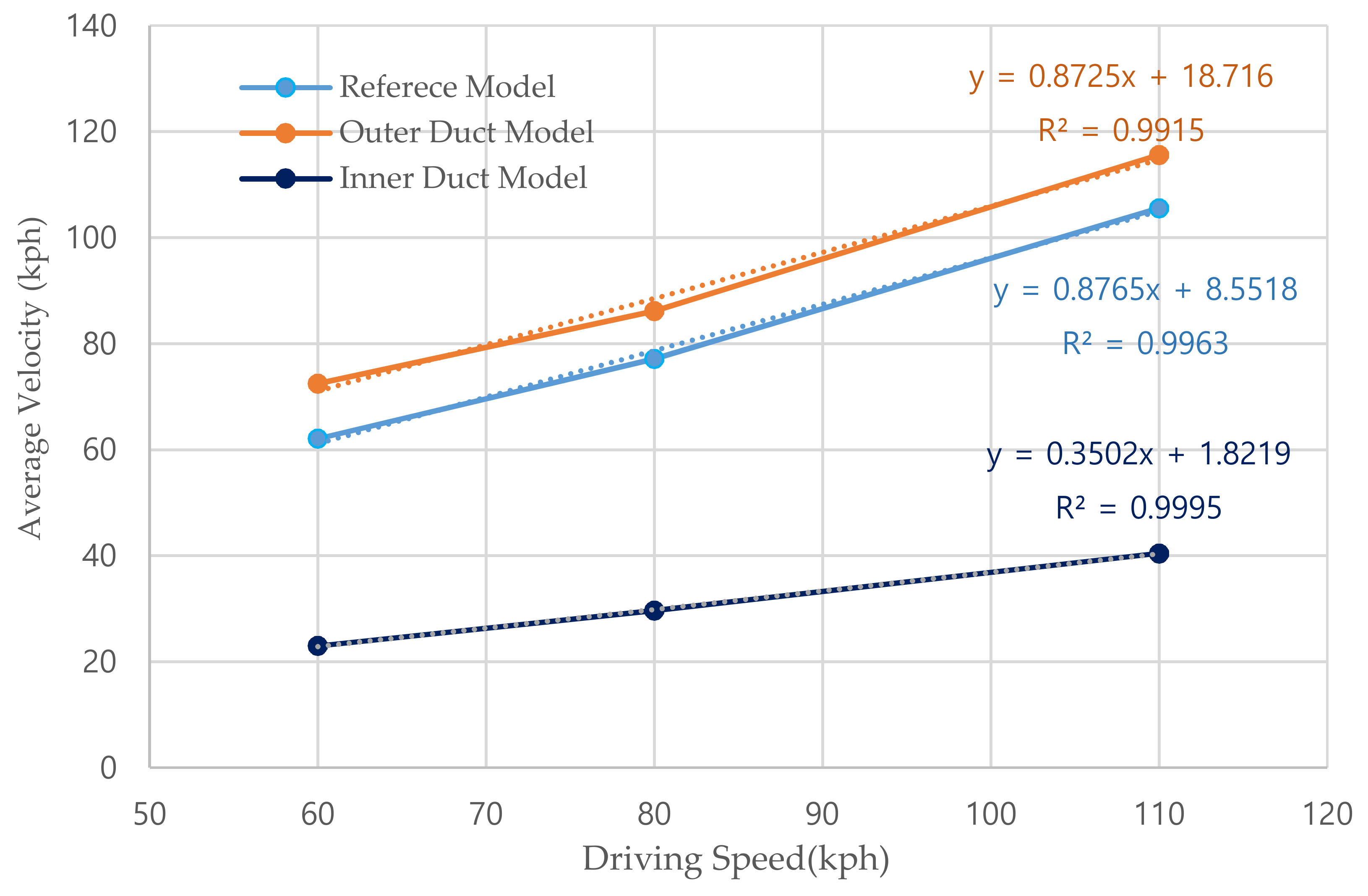
Table 2 summarizes the airflow velocities at the gutter, the mirror surface, and the outer edge of the three mirror models. At high driving speeds, the average velocity increased for the reference and outer duct models. However, the inner duct model dramatically reduced the airflow velocity at all of the points. The velocity especially decreased at the outer edge of the inner duct model, which was quite large compared to the other cases. The additional inner dent on the mirror housing distributed the high-speed airflow that passed through the outer edge and enhance velocity profiles around the mirror housing. Accordingly, the velocity difference between the edge and gutter of the inner-duct OSRVM was quite small compared to the other mirror models. At the mirror surface of the inner duct model, the airflow velocity was less than 25 kph for all of the vehicle speeds.
Figure 7 shows the average flow velocity of the three points (gutter, mirror, and edge) for the vehicle speeds (60 kph, 80 kph, and 110 kph). The increasing rate (slope) of the average velocity by the vehicle speed was similar for the reference and the outer duct models. However, the inner duct model shows the low rate of velocity change with the slope of 0.35. The addition of two inside ducts on the design of the mirror housing improved the homogenous airflow around the OSRVM.
Aerodynamic noise is mainly due to pressure fluctuations by the changes of the flow velocity and the air density, which are related to vorticity. Table 3 represents the magnitude and variation of vorticity at the gutter and the edge of the three OSRVM models.
High vorticity at the gutter between the A-pillar and the mirror of the reference and outer duct models resulted in dense airflow and high-pressure fluctuation. Moreover, a high vorticity difference between the gutter and the outside edge affected the flow separation and sound radiation at the trailing edge of the mirror. Unlike the cases of the reference and outer duct models, both the vorticity magnitude and the vorticity difference between the gutter and edge of the inner duct model dramatically decreased, enhancing the homogenous airflow and noise radiation around the mirror housing.
4. Conclusions
In this study, we proposed a new OSRVM model with additional inner dents on the inner and outer edges of the mirror housing in order to enhance the aerodynamic flow and noise around the mirror. Based on computational fluid dynamics (CFD) analysis, the aerodynamic flow characteristics and sound pressure levels of the proposed model were compared with the original and outer duct mirror models for three vehicle speeds (60 kph, 80 kph, and 110 kph). The comparative studies at three major points (the gutter, the center of the mirror surface, and the outside edge) of the mirror housing showed that the velocity/vorticity profiles and sound pressure levels of the proposed OSRVM model with the inner ducts were dramatically improved.
This proposed OSRVM model with inner dents provides a new design methodology for the enhancement of the aerodynamic flow and noise characteristics, while satisfying the size constraint to secure its visual angle without a reduction in size and additional installation.
Acknowledgments
This research was supported by C0541063 of Academic-Industrial Project of Ministry of SMEs and Startups (Development of Spherical involute bevel gear design and precision forging process for vehicle limited-slip differential) and 2015M2B2A9031556 of the National Research Foundation of Korea funded by Ministry of Science ICT.
Author Contributions
Yong-Ju Chu designed and optimized the OSRVM. Yong-Sang Shin contributed the assisted Computational Fluid Dynamics analysis. Seung-Yop Lee contributed the theoretical analysis.
Conflicts of Interest
The authors declare no conflict of interest.
References
- Cerrato, G. Automotive sound quality—Powertrain, road and wind noise. Sound Vib. 2007, 43, 16–24. [Google Scholar]
- Jaitlee, R.; Alam, F.; Watkins, S. Pressure Fluctuations on Automotive Rear View Mirrors; SAE Paper 2007-01-0899, SP-2066; Society of Automotive Engineers: Warrendale, PA, USA, 2007. [Google Scholar]
- Alam, F.; Jaitlee, R.; Watkins, S. Aerodynamic Effects on an Automotive Rear Side View Mirror. In Proceedings of the 16th Australasian Fluid Mechanics Conference, Gold Coast, Australia, 3–7 December 2007; pp. 762–765. [Google Scholar]
- Lounsberry, T.H.; Gleason, M.E.; Puskarz, M.M. Laminar Flow Whistle on a Vehicle Side Mirror; SAE Paper, 2007-01-1549; Society of Automotive Engineers: Warrendale, PA, USA, 2007. [Google Scholar]
- Watkins, S.; Oswald, G. The flow field of automobile add-ons-with particular reference to the vibration of external mirrors. J. Wind Eng. Ind. Aerodyn. 1999, 82, 541–554. [Google Scholar] [CrossRef]
- Kim, J.-H.; Han, Y.O.; Lee, M.H.; Hwang, I.H.; Jung, U.H. Surface flow and wake structure of a rear view mirror of the passenger car. In Proceedings of the Bluff Bodies Aerodynamics & Applications (BBAA) VI, Milan, Italy, 20–24 July 2008. [Google Scholar]
- Kim, J.-H.; Han, Y.O. Experimental investigation of wake structure around an external rear view mirror of a passenger car. J. Wind Eng. Ind. Aerodyn. 2011, 99, 1197–1206. [Google Scholar] [CrossRef]
- Ask, J.; Davidson, L. A numerical investigation of the flow past a generic side mirror and its impact on sound generation. J. Fluids Eng. 2009, 131, 061102. [Google Scholar] [CrossRef]
- Ono, K.; Himeno, R.; Fukushima, T. Prediction of wind noise radiated from passenger cars and its evaluation based on auralization. J. Wind Eng. Ind. Aerodyn. 1999, 81, 403–419. [Google Scholar] [CrossRef]
- Murad, N.; Nase, J.; Alam, F.; Watkins, S. Computational fluid dynamics study of vehicle A-pillar aero-acoustics. Appl. Acoust. 2013, 74, 882–896. [Google Scholar] [CrossRef]
- Frank, H.M.; Munz, C.-D. Direct aeroacoustics simulation of acoustic feedback phenomena on a side-view mirror. J. Sound Vib. 2016, 371, 132–149. [Google Scholar] [CrossRef]
- Werner, M.J.; Wurz, W.; Kramer, E. Experimental investigation of an aeroacoustics feedback mechanism on a two-dimensional side mirror model. J. Sound Vib. 2017, 387, 79–95. [Google Scholar] [CrossRef]
- Grahs, T.; Othmer, C. Evaluation of Aerodynamic Noise Generation: Rarameter Study of a Generic Side Mirror Evaluating the Aeroacoustic Source Strength. In Proceedings of the European Conference on Computational Fluid Dynamics, Egmond aan Zee, The Netherlands, 5–8 September 2006. [Google Scholar]
- Viswanath, P.R. Aircraft viscous drag reduction using riblets. Prog. Aerosp. Sci. 2002, 38, 571–600. [Google Scholar] [CrossRef]
- Zastawny, M. Numerical simulation of wing vortex generators—Methodologies and validation. Aeronaut. J. 2016, 120, 627–650. [Google Scholar] [CrossRef]
- Olsson, M. Designing and Optimizing Side-View Mirrors; Dept. of Applied Mechanics, Chalmers University of Technology: Gothenburg, Sweden, 2011. [Google Scholar]
- Wang, Y.; Gu, A.; Li, W.; Lin, L. Evaluation of aerodynamic noise generation by a generic side mirror. Int. J. Mech. Aerosp. Ind. Mechatron. Manuf. Eng. 2010, 4, 120–127. [Google Scholar]
- ANSYS, INC. ANSYS Fluent User’s Guide; ANSYS, INC.: Canonsburg, PA, USA, 2016. [Google Scholar]
Figure 1.
Three-dimensional (3D) scanning process to gather a 3D computer-aided design (CAD) model and three types of OSRVM models: (a) 3D scanning apparatus; (b) Extraction of the mirror shape from the scanned data; (c) Reference model; (d) Outer duct model; (e) Inner duct model.
Figure 1.
Three-dimensional (3D) scanning process to gather a 3D computer-aided design (CAD) model and three types of OSRVM models: (a) 3D scanning apparatus; (b) Extraction of the mirror shape from the scanned data; (c) Reference model; (d) Outer duct model; (e) Inner duct model.

Figure 2.
(a) The location of gutter, edge, and mirror of the outside rear view mirror (OSRVM) models; (b) Computational domain around the side mirror; (c) Mesh data of the inner duct OSRVM models.
Figure 2.
(a) The location of gutter, edge, and mirror of the outside rear view mirror (OSRVM) models; (b) Computational domain around the side mirror; (c) Mesh data of the inner duct OSRVM models.

Figure 3.
Flow velocity contour with vector field (a–c) and maximum sound pressure level (d–f) around the reference outside rear view mirror (OSRVM) model at 23 °C and 50% humidity conditions for three vehicle speeds: (a,d) 60 kph, (b,e) 80 kph, and (c,f) 110 kph.
Figure 3.
Flow velocity contour with vector field (a–c) and maximum sound pressure level (d–f) around the reference outside rear view mirror (OSRVM) model at 23 °C and 50% humidity conditions for three vehicle speeds: (a,d) 60 kph, (b,e) 80 kph, and (c,f) 110 kph.

Figure 4.
The graph chart of the sound pressure level of the reference OSRVM model for various relative humidities and temperatures: the gutter from (a–c) and the surface of the mirror from (d–f) for three speed cases of 60 kph, 80 kph, and 110 kph.
Figure 4.
The graph chart of the sound pressure level of the reference OSRVM model for various relative humidities and temperatures: the gutter from (a–c) and the surface of the mirror from (d–f) for three speed cases of 60 kph, 80 kph, and 110 kph.

Figure 5.
Flow velocity contour with vector field (a–c) and maximum sound pressure level (d–f) of the second OSRVM model with two inner ducts at 23 °C and 50% humidity conditions for three vehicle speeds: (a,d) 60 kph, (b,e) 80 kph, and (c,f) 110 kph.
Figure 5.
Flow velocity contour with vector field (a–c) and maximum sound pressure level (d–f) of the second OSRVM model with two inner ducts at 23 °C and 50% humidity conditions for three vehicle speeds: (a,d) 60 kph, (b,e) 80 kph, and (c,f) 110 kph.
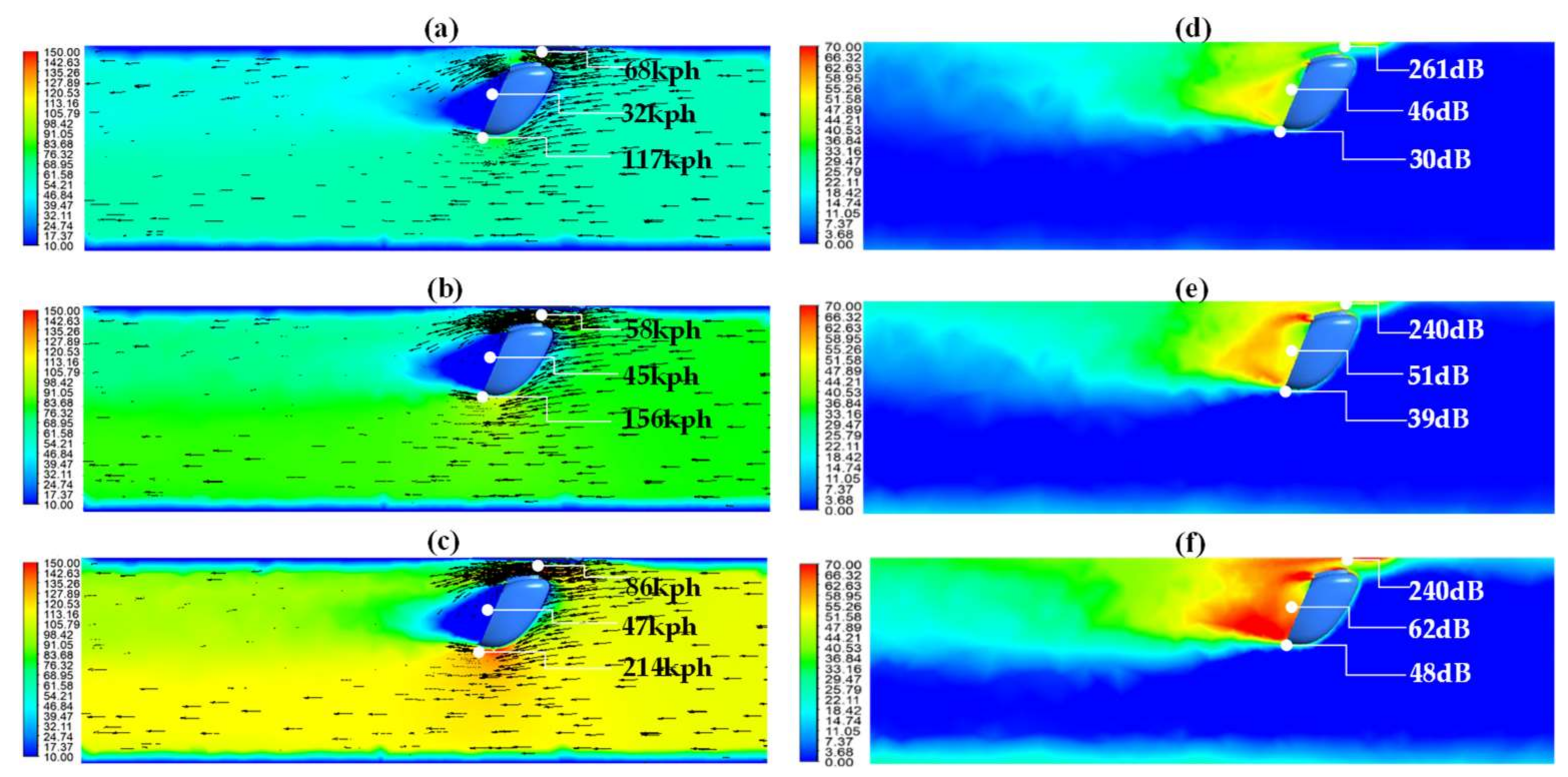
Figure 6.
Flow velocity contour with vector field (a–c) and maximum sound pressure level (d–f) of the third OSRVM model with two inner ducts at 23 °C and 50% humidity condition for three vehicle speeds: (a,d) 60 kph, (b,e) 80 kph, and (c,f) 110 kph.
Figure 6.
Flow velocity contour with vector field (a–c) and maximum sound pressure level (d–f) of the third OSRVM model with two inner ducts at 23 °C and 50% humidity condition for three vehicle speeds: (a,d) 60 kph, (b,e) 80 kph, and (c,f) 110 kph.
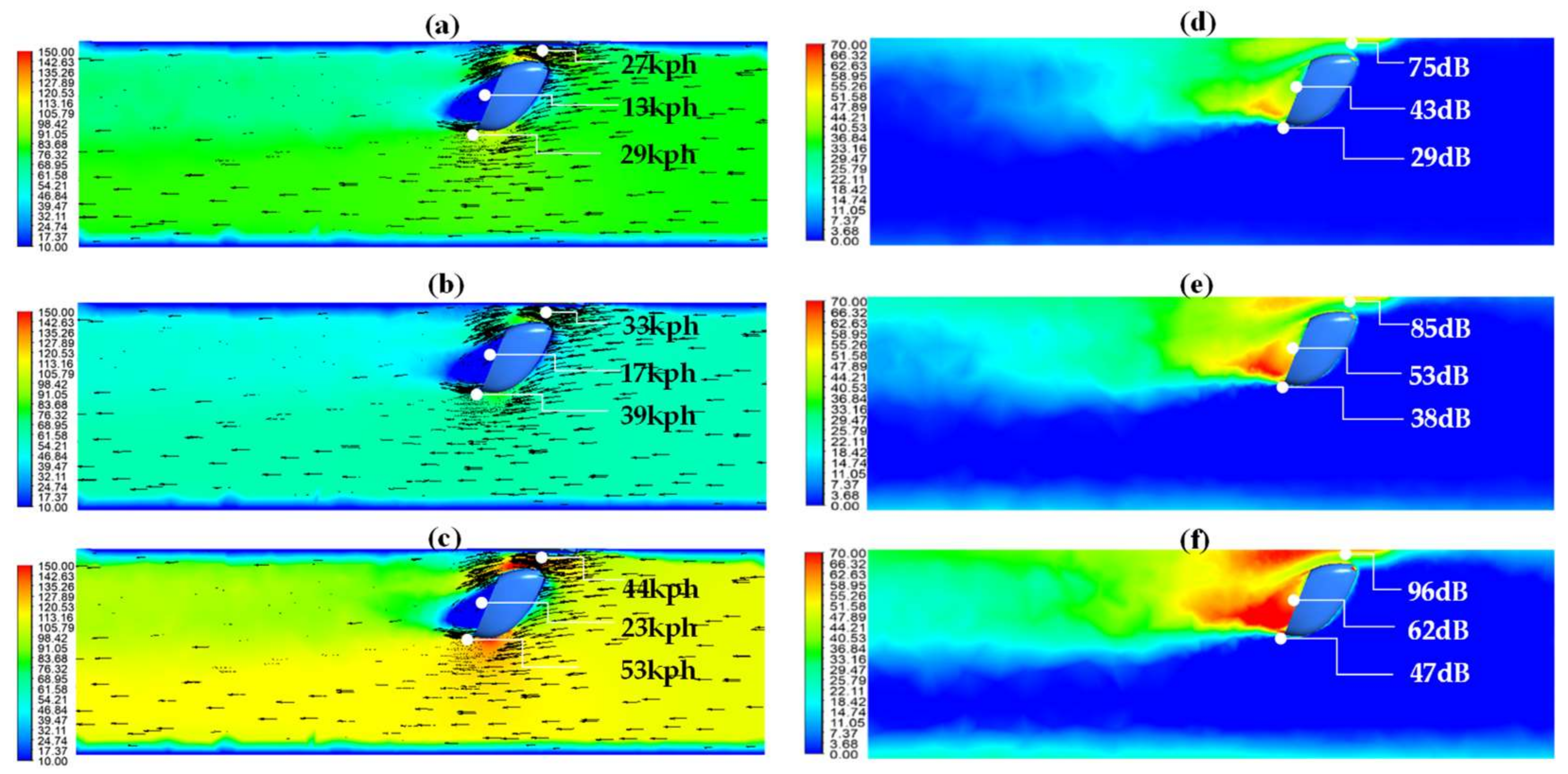
Figure 7.
Comparisons of the average velocity and the increasing rate of the three OSRVM models for the three driving speeds.
Figure 7.
Comparisons of the average velocity and the increasing rate of the three OSRVM models for the three driving speeds.

Table 1.
The inlet conditions of vehicle velocities, temperatures and relative humidity in computational fluid dynamics (CFD) simulation.
Table 1.
The inlet conditions of vehicle velocities, temperatures and relative humidity in computational fluid dynamics (CFD) simulation.
| Vehicle Speed (kph) | 60 (Urban or City) | 80 (Highway) | 110 (Freeway) |
| Temperature (°C) | 18 | 23 | 25 |
| Relative Humidity (%) | 30 | 50 | 70 |
Table 2.
Simulation results of velocities according to vehicle driving speed at the gutter, the mirror surface, and the edge of the three OSRVM models.
Table 2.
Simulation results of velocities according to vehicle driving speed at the gutter, the mirror surface, and the edge of the three OSRVM models.
| Type | Vehicle Speed (kph) | Measure Points | Average (kph) | Difference (Edge − Gutter) | ||
|---|---|---|---|---|---|---|
| Gutter (kph) | Mirror (kph) | Edge (kph) | ||||
| Reference Model | 60 | 54 | 31 | 102 | 62.3 | 48 |
| 80 | 54 | 43 | 135 | 77.3 | 81 | |
| 110 | 73 | 59 | 184 | 105.3 | 111 | |
| Outer Duct Model | 60 | 68 | 32 | 117 | 72.3 | 49 |
| 80 | 58 | 45 | 156 | 86.3 | 98 | |
| 110 | 86 | 47 | 214 | 115.7 | 128 | |
| Inner Duct Model | 60 | 27 | 13 | 29 | 23.0 | 2 |
| 80 | 33 | 17 | 39 | 29.7 | 6 | |
| 110 | 44 | 23 | 53 | 40.0 | 9 | |
Table 3.
Simulation results of vorticities according to vehicle driving speed between the gutter and the outside edge of the three OSRVM models.
Table 3.
Simulation results of vorticities according to vehicle driving speed between the gutter and the outside edge of the three OSRVM models.
| Type | Vehicle Speed (kph) | Vorticity: Measure Points | (A − B)/A (%) | ||
|---|---|---|---|---|---|
| A: Gutter (1/s) | B: Edge (1/s) | A − B | |||
| Reference Model | 60 | 689 | 241 | 448 | 65.0 |
| 80 | 664 | 242 | 422 | 63.6 | |
| 110 | 906 | 326 | 579 | 64.0 | |
| Outer Duct Model | 60 | 629 | 274 | 355 | 56.4 |
| 80 | 472 | 207 | 264 | 56.1 | |
| 110 | 784 | 343 | 440 | 56.3 | |
| Inner Duct Model | 60 | 251 | 287 | −37 | −14.3 |
| 80 | 347 | 375 | −28 | −8.1 | |
| 110 | 454 | 553 | −99 | −21.8 | |
© 2018 by the authors. Licensee MDPI, Basel, Switzerland. This article is an open access article distributed under the terms and conditions of the Creative Commons Attribution (CC BY) license (http://creativecommons.org/licenses/by/4.0/).
Share and Cite
MDPI and ACS Style
Chu, Y.-J.; Shin, Y.-S.; Lee, S.-Y. Aerodynamic Analysis and Noise-Reducing Design of an Outside Rear View Mirror. Appl. Sci. 2018, 8, 519. https://doi.org/10.3390/app8040519
AMA Style
Chu Y-J, Shin Y-S, Lee S-Y. Aerodynamic Analysis and Noise-Reducing Design of an Outside Rear View Mirror. Applied Sciences. 2018; 8(4):519. https://doi.org/10.3390/app8040519
Chicago/Turabian StyleChu, Yong-Ju, Yong-Sang Shin, and Seung-Yop Lee. 2018. "Aerodynamic Analysis and Noise-Reducing Design of an Outside Rear View Mirror" Applied Sciences 8, no. 4: 519. https://doi.org/10.3390/app8040519
Note that from the first issue of 2016, this journal uses article numbers instead of page numbers. See further details here.