Novel Automatic Idle Speed Control System with Hydraulic Accumulator and Control Strategy for Construction Machinery

College of Mechanical Engineering and Automation, Huaqiao University, Xiamen 361021, China
*
Author to whom correspondence should be addressed.
Appl. Sci. 2018, 8(4), 496; https://doi.org/10.3390/app8040496
Submission received: 23 January 2018
/
Revised: 6 March 2018
/
Accepted: 19 March 2018
/
Published: 26 March 2018
(This article belongs to the Special Issue Power Transmission and Control in Power and Vehicle Machineries)
Abstract
:To reduce the energy consumption and emissions of the hydraulic excavator, a two-level idle speed control system with a hydraulic accumulator for the construction machinery is proposed to reduce the energy consumption and improve the control performance of the actuator when the idle mode is cancelled. The structure and working principle are analyzed. The hydraulic accumulator (HA) is used to store the energy, which can provide backup pressured fluid when the idle mode is cancelled. Then, a method of how to set the pressure differential between the hydraulic accumulator and the load is proposed and the control law is discussed. The test rig is built. The experimental result shows that the idle speed can be switched among the first idle speed, the second idle speed and the normal speed automatically. Though the idle speed in the novel system can be reduced more than that in the conventional automatic idle speed control system (AISCS), the proposed system can still build the actuator pressure more quickly when the idle mode is cancelled. When compared to the system without the idle speed control, the energy saving of the proposed system is about 67%. The proposed two-level idle speed control system with a HA can achieve a high energy efficiency and a good control performance.
1. Introduction
Energy saving and environment friendly become the primary demands for the construction machinery under the environment of stringent emission regulations. Currently, there are several energy saving methods for construction machinery, for example, positive and negative flow control system [1,2], load sensing control [3,4], hybrid power system [5,6,7,8], energy regeneration [9,10,11,12] and automatic idle speed control system (AISCS) [13], are proposed and utilized in some models. Whether it is positive and negative flow control system or load sensing control, the purpose of them is to balance the output of the pump and the requirement of the load to reduce the energy loss. They do reduce the throttle loss and improve the efficiency of the machine. In hybrid power systems, the engine works at an optimal power consumption area to reduce fuel consumption and emissions via more than one power train [6,7,8]. Because there is more than one power train, the structure is complex and the cost is high, which limits its wide application. However, the above energy saving technologies mainly concentrate on the working time of the construction machinery. In fact, construction machines consume about 30% of the total energy in the idle state. AISCS is used to reduce the fuel consumption and emissions in the idle time. Commonly, the traditional AISCS is utilized to adjust the engine speed switching between the first idle speed, sometimes there is second idle speed and the normal working speed.
A lot of researches have been reported in the field of AISCS of automobiles. He et al. investigated a CNG engine and reduced the idle speed from original 800 rpm to 700 rpm [14]. Li et al. set the desired idle speed to 611 rpm instead of the normal (production) idle speed of 740 rpm, and used the sliding mode control to AISCS [15]. Though a low idle speed could reduce the fuel consumption, the cost was to increase the risk of missing fire or even stalling. That is to say, the transition to and from idle speed should be smooth and well controlled [16]. Many research devoted themselves to solving the AISCS problems with different control strategies [17,18,19,20,21].
Though some useful results have been achieved on the AISCS of automobiles and the technology is relatively mature, only a few research on the AISCS have been developed for construction machinery. Due to the different working conditions, the AISCS used in automobiles cannot be adopted to construction machinery directly. Xiong et al. analyzed the working principle and the implementation method of the AISCS in a rotary drilling rig [22]. They tested the fuel consumption under different speed and found that the speed when the minimum fuel consumption achieved was the preset idle speed. Liu designed an AISCS according to the working conditions, speed sensing, and engine power matching. The adjusting time of the engine from idle speed to the rated speed was about 2 s [23]. Hao optimized the duty ratio of the PWM, minimum ramping time, and idle speed through adapting the adaptive control method and achieved a better energy saving effect [24]. Those researches were still based on the traditional engine and the idle speed cannot be too low to avoid the misfire. Meantime, the hydraulic system still utilized the traditional pumps system. Therefore, the adjusting time of the transition from the idle speed to the normal speed of the engine cannot be very short and the pumps cannot build the pressure quickly to drive the actuator when the idle mode is cancelled. This leads to the instability of the actuator movement and a slow response to the working signal. Hydraulic accumulator (HA) is widely used in the hydraulic systems because it can be used as an auxiliary power source to supply pressured oil in a short time. When the pump cannot supply enough oil to the actuator at the moment that the AISCS is cancelled, HA is a best choice to supply the oil that the actuator needed, despite its short supply time. Though the engine using the AISCS can consume less fuel and reduce emissions, there are still emissions, especially when the idle speed cannot be set too low. While the electric motor (EM) is true zero emissions and it has a high efficiency within a wider speed range. Therefore, if the EM and HA are used in the AISCS of the construction machinery, the above problems may be avoided. This paper is to verify the feasibility of this idea.
In this research, a prototype of a two-ton hydraulic excavator that is (HE) driven by the EM for experiment has been built. The key object of this research is the novel AISCS with the HA for a two-ton HE. The remainder of this paper is organized as follows: Section 2 gives the structure and working principle of the AISCS with HAs. The control strategy of the proposed AISCS is discussed in detail in Section 3. Then, the experiment results are analyzed in Section 4. Conclusions are presented in Section 5.
2. Structure and Working Principle of the Novel AISCS
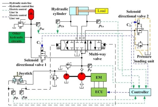
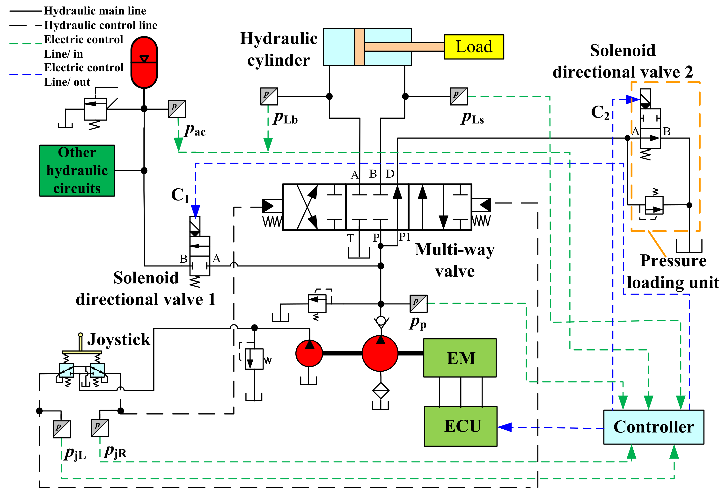
Figure 1 and Figure 2 show the configuration of the traditional and the proposed AISCS, respectively. The multi-way valves that are used in Figure 1 and Figure 2 are controlled by the pilot pressure produced by the joystick and the valve stroke is proportional to the pilot pressure. The working principle of the traditional AISCS is when the joystick returns to the middle position, the multi-way valve works at the middle position too. The output of the pump flows to the tank through the multi-way valve. When the controller detects the time that the joystick stays at the middle position is larger than a set value, the engine speed drops to a low value to reduce the fuel consumption. When the joystick leaves the middle position, the multi-way valve moves to the corresponding position and the engine accelerates to the normal speed. There is a delay when the actuator starts to move and due to the low pressure in the working chamber of the actuator, the movement of the actuator is unstable. When compared to the traditional AISCS, the proposed AISCS has the following advantages:
- A HA is connected to the outlet of the pump via a solenoid directional valve 1. The HA is used to store energy during the first level idle mode, which can be serve as an auxiliary energy source to drive the actuator when the idle mode is cancelled.
- There is a pressure loading unit at the bypass way of the multi-way valve. When the multi-way valve is at middle working position and the solenoid directional valve 2 is powered off, it can separate the pump from the tank by the solenoid directional valve 2 and charge the HA.
- The EM has a faster response than the traditional engine and a high efficiency within a wider speed range. Thanks to the utilization of the EM, there is no pollution at all.
Therefore, the pressure in the working chamber of the actuator can be built quickly to drive the load with the assistance of the HA. Meanwhile, the idle speed can be set to a low value to obtain good energy saving and decrease noise, even if the response of the EM cannot be guaranteed.
3. Control Strategy
There are two goals of the control strategy. One is to make EM speed be as low as possible to reduce energy consumption. However, the low speed should not be at the cost of control performance and pump suction capacity. As the pump suction capacity cannot be improved easily, the other goal of control strategy is to guarantee the control performance when the idle mode is cancelled, which creates a sense of the hydraulic cylinder moving at the same speed as the target velocity, which is decided by the joystick. In other words, the input pressure pp of the multi-way valve should be built up as quickly as possible. However, the EM speed cannot be increased rapidly from the idle speed to its normal speed, especially when the idle speed is low.
3.1. Optimization of Pressure Differential Δp between the HA and the Maximum Load Pressure
One case should be considered: as long as the EM starts to run, the joystick returns to its maximum position in an instant and the EM speed cannot reach to its target speed as quickly as possible. Hence, the flow rate of the pump will be too low to drive the load in time and the velocity of the load cannot be guaranteed. Meanwhile, when the HE works in a crane mode and pilot-oil discloses the multi-way valve, the output pressure of the pump is at a rather low level and the pressure in the hydraulic cylinder will drop suddenly with a big oscillation, especially in the case that the load is heavy and the load had not been lowered to the ground. As a matter of fact, one of the disadvantage of the HA is that only when the pressure of the HA is larger than the load pressure can it release the oil to drive the load. If the pressure differential Δp between the HA and the maximum load pressure is too high, though the actuator will start immediately, excess loss will be produced across the hydraulic control valve. While if the pressure differential Δp between the HA and the maximum load pressure is too low, it cannot build up the pressure quickly to drive the load. Therefore, the pressure differential Δp between the HA and the maximum load pressure should be optimized to ensure the control performance and the energy saving.
The maximum load pressure pLmax is determined from the expression
where, pLb is the non-rod side chamber of the hydraulic cylinder, MPa. pLs is the rod side chamber of the hydraulic cylinder, MPa.
The target velocity of the actuator is given by
where, k is the proportionality coefficient between the target velocity and the joystick pressure.
The actual velocity of the load is calculated as
where, qp is the displacement of the pump, m3/rad. np is the speed of the pump, rad/s. Cip and Cep are the internal and external leakage coefficient of the pump, respectively, m3/(Pa∙s). pp is the output port pressure of the pump, Pa. Qbp is the bypass flow rate of the pump, m3/s. Qac is the flow rate of the HA, and m3/s. AL is the effective area of driving chamber of the cylinder, m2.
The Boyle’s law expression for this case is
where, pa0 is the pre-charge pressure of the HA, MPa. V0 is the gas volume under the pressure pa0, m3. pax is the pressure of the HA, MPa. ΔV is the volume change of the HA, m3. n is the polytrophic exponent, in this research, and n can be set at 1.4 because the time for releasing the flow to the multi-way valve is short, which is less than 5 s. When the HA is charged, the minus sign is chosen in Equation (4).
The flow rate of the HA can be achieved by differentiating the Equation (4) with respect to time, as follows:
When the idle mode is cancelled, the HA is the main power device to drive the load in the initial stage, namely,
When considering that the pressures of HA satisfies,
where pa1 and pa2 are the minimum and maximum working pressure of HA, respectively.
0.25pa2 < pa0 < 0.9pa1
Then, the pressure change rate of the HA in Equation (5) can be obtained by
When the polytrophic exponent n is 1.4, the pressure change rate of the HA can be rewritten as,
Seen from Figure 2, the pressure differential Δp between the HA and the load is equal to the sum of the pressure change of the HA and the pressure drop across the solenoid directional valve 1, multi-way valve, and oil pipes. Then, the pressure differential Δp between the HA and the load is developed as
where pL is the load pressure, MPa. Δpvalve is pressure drop across the solenoid directional valve 1, multi-way valve, and oil pipes, MPa. However, the actual velocity of the load, which is decided by the joystick and the load on the next working cycle is uncertain. Hence, the maximum target velocity of the actuator is used to substitute the actual velocity. Therefore, the pressure differential Δp between the HA and the load is developed as
where vtmax is the maximum target velocity of the actuator, m/s.
According to Equation (11), the pressure differential Δp can be divided into two parts: the first part is the drop pressure in directional valve 1, multi-way valve, and oil pipes. It can be considered as a constant. The second part is the pressure change of the HA. It can be deduced that the pressure change of the HA depends on the rated volume V0 of the HA, the pre-charge pressure pa0 of the HA, and the maximum velocity vtmax of the actuator.
3.2. Control Law
The overall control process of the AISCS of Figure 2 is illustrated in Figure 3. When the joystick returns to the middle position, the controller detects that the pressure differential of the joystick is under the preset small positive value and sends the pilot control oil to the multi-way valve to make it work at the middle position. The proposed AISCS is to control EM speed to be switched between the different values, including the switch from the normal working speed to the first idle speed, the second idle speed, and that from the two idle speeds to its normal working speed. When reducing EM speed, the main consideration is the energy saving of the system. While the set value of the idle speed is the primary factor that influences the energy consumption. When the idle mode is cancelled, the control performance is the main consideration. Therefore, the time for building up the pressure of the pump should be smooth and short. Taking the self-suction capacity of the pump into account, the first level idle speed is set to 800 rpm and the second level idle speed is set to 500 rpm, because the HA can help the pump to build up the pressure quickly. During the different process, the control strategy changes accordingly. The control strategy is based on the following principles.
- ●
- Mode 1: First level idle mode
When the time of the joystick backs to the middle position is longer than time T1, the controller makes the EM speed reduce to the first level idle speed n1 to reduce the energy loss. Meanwhile, the maximum load pressure pLmax is adopted to decide to charge the HA by the pump or not. When the pressure differential between the maximum load pressure and the HA is larger than the preset value ∆pac, then the solenoid directional valves 1 and 2 are powered on. Then the pump charges the HA via solenoid directional valve 1. After the pressure of the HA increases to the upper limited value, the solenoid directional valves 1 and 2 are powered off. The pump is connected to the tank through solenoid directional valve 2 and is unloaded.
- ●
- Mode 2: Second level idle mode
With an HA in AISCS, the HA had store a certain amount of energy in the first level idle mode. When the time of the joystick backs to middle position is longer than time T1 + T2 and the pressure of HA is under the threshold values, then the controller makes the EM work at the second level idle speed n2, which is lower than the first level idle speed n1 to further reduce the energy consumption.
- ●
- Mode 3: Idle mode is cancelled
When the joystick leaves its middle position, the AISCS is cancelled. In a HE, the joysticks are the most common interfaces between the drivers and the hydraulic manipulators. The target velocity of the actuator is characterized by the status of the joystick. The joystick signal gives a pressure differential. The target velocity of the actuator is the control object, which is compared with the joystick command through a conversion gain, as shown in Equation (2). When considering the dynamic response of EM, it cannot quickly reach to the normal speed which is usually about 1800 rpm. That is to say, the pump cannot build up the pressure quickly to drive the actuator. Hence, the actuator should be driven by the pump and the HA. In this case, both the solenoid directional valves 1 and 2 are powered on. The stored oil in the HA is released through solenoid directional valve 1 to the inlet of the multi-way valve to help the pump build up the pressure quickly to drive the actuator. The pressure of HA decreases with the discharging process and the load pressure changing, according to the pressure of HA. When the pump pressure is larger than the HA pressure, the solenoid directional valve 1 is powered off, and the actuator is driven by the pump only. The proportion of the flow rate supplied by the HA and the pump is scheduled to achieve a smooth and quick movement of the actuator.
During this control process, the HA pressure is the control object, which is achieved by controlling the on or off of the solenoid directional valves 1 and 2. Further, when the AISCS is cancelled, the pressure differential Δp between the HA and the load is detected and controlled by the sensor signals shown in Figure 2. Due to the pressure, the differential is proportional to the target velocity of the actuator, which is characterized by the status of the joystick shown in Equation (2), therefore, the pressures of the joysticks are the key to monitor.
4. Experiment Research
4.1. Test Rig
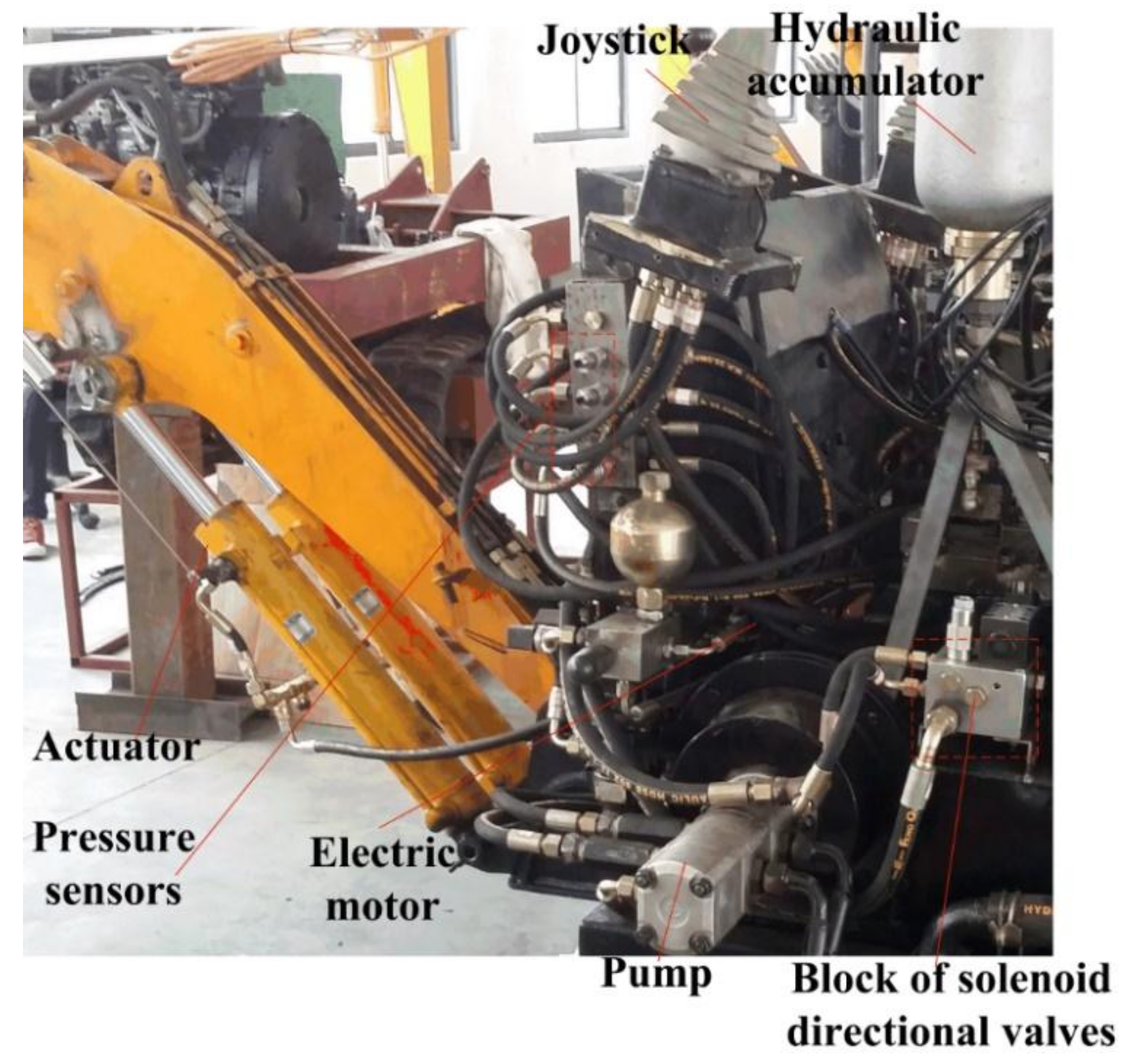
To investigate the effects of the control strategy of AISCS, a test rig was developed, which is shown in Figure 4. The EM consists of two coaxial motors. The pump is a triple pump, including the main pump and the pilot pump. The hydraulic cylinder of the arm is chosen as the actuator to control. A 1.6 L HA is installed and the solenoid directional valves are integrated into one block. The sensors are installed to detect the status of the key pressures. The basic parameters of the test rig are listed in Table 1. To compare and analyse conveniently, the control signal of the joystick is the same and the boom cylinder has the same start/end points and displacements when the same type experiment is carried out. Because the idle speed period and the performance when the idle speed is cancelled are the main considerations of this research, the working period of the construction machinery, including digging, swing, and other performance, which is the same to the traditional construction machinery, is not discussed. The following part discusses the period when the joystick backs to the middle position and the system works in the idle mode.
4.2. Control Performance
The control performance is used to evaluate the responsiveness of the pressure of the actuator’s cylinder to follow the signal that is produced by the joystick. If the pressure of the actuator cylinder can reach its target value quickly and smoothly, it is considered as a good control performance.
Figure 5 shows the EM speed of the AISCS and joystick pressure according to the state of the joystick. It can be seen that the EM speed changes according to the state of the joystick. The joystick backs to the middle position and the actuator stops to work at time 7 s. When the controller detects the joystick staying at middle position for 8 s, which means that the actuator stops working for 8 s, and then the controller makes the EM work at the first level idle speed (800 rpm) from time 15 s. After 20 s and if the joystick is still at the middle position, then the controller makes the EM work at the second level idle speed (500 rpm) from time 35 s to further reduce the energy consumption. When the controller detects the joystick leaves the middle position, it makes the EM accelerate to its normal working speed (1800 rpm). Hence, the EM can switch the speed among the normal speed (1800 rpm), first level idle speed (800 rpm), and the second level idle speed (500 rpm), judging by the control strategy.
Figure 6 describes the pressures of the HA, pump, joystick, and load during the proposed AISCS process. When the joystick backs to the middle position at time 7 s, the actuator stops, therefore, the velocity and the pressure of the actuator are close to zero and the pump is unloading. When the system works at the first level idle mode at time 15 s, the actuator still does not work, while the pump supplies the oil to the HA and both the pressures of the HA and pump rise until the pressure of the HA reaches the upper limited value. Then, the pump is unloading through the solenoid directional valve 2. When the joystick leaves the middle position at time 40 s, both the HA and the pump supply the oil to the actuator to make it work quickly. As the EM speed cannot reach its target speed as quickly as possible, the outlet pressure of the pump is less than the load pressure, while the pressure of the HA is above the load pressure. Accordingly, only the HA can drive the actuator in this working mode at the time from 40 s to 44.6 s. The pressure differential between the HA and the load pressure almost keeps constant to ensure that the HA have the capability to release the oil to the actuator. This indicates that the HA can be an auxiliary energy to build up the pressure of the actuator quickly. When the outlet pressure of the pumps reaches the pressure of the HA, the HA stops to work and only the pumps drive the actuator. Even though it takes 2–5 s for the EM’s acceleration process, the system can still build up the pressure quickly. Hence, the pressure differential control strategy can guarantee the control performance for the actuator. Both Figure 5 and Figure 6 indicate that the proposed AISCS can realize the preset goals and the control strategy works well.
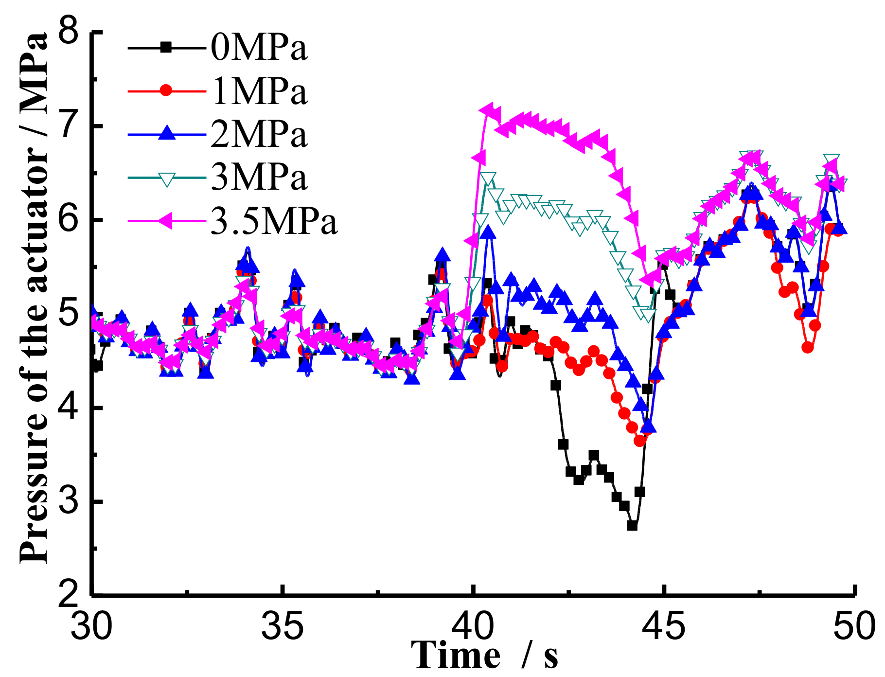
Figure 7 shows the pressures of the non-rod chamber of the actuator cylinder under different pressure differential in the proposed AISCS process. The pressure differential Δp may influence the dynamic response of the actuator movement. The larger the pressure differential, the more quickly the actuator pressure is built up. When the pressure differential is 0 MPa, the pressure of HA is not larger than the load pressure and HA cannot release oil to the actuator. The pressure is only built up by the pump, so the load pressure drops at the beginning when AISCS is cancelled. This can conclude that the proposed AISCS can build up the pressure quickly to drive the actuator with the suitable pressure differential. The release characteristics of the HA is the key factor to decide the pressure differential Δp, while the dynamic response of the EM is not rigorous in the proposed system.
4.3. Energy Saving
Energy saving is the main consideration of the modern construction machinery. It can be calculated by the energy that is consumed by the traditional construction machinery and that of the proposed construction machinery. Though the working time, which is about 20 s, is periodic, the idle time is irregular and the actual idle time depends on the driver. Hence, the idle mode for testing the energy saving in the novel automatic idle speed control system with hydraulic accumulator works only once.
The energy consumed of the system can be characterized by the output energy of the pump, as follows,
where, Ep is the output energy of the pump, J. ηc is the volumetric efficiency of the pump.
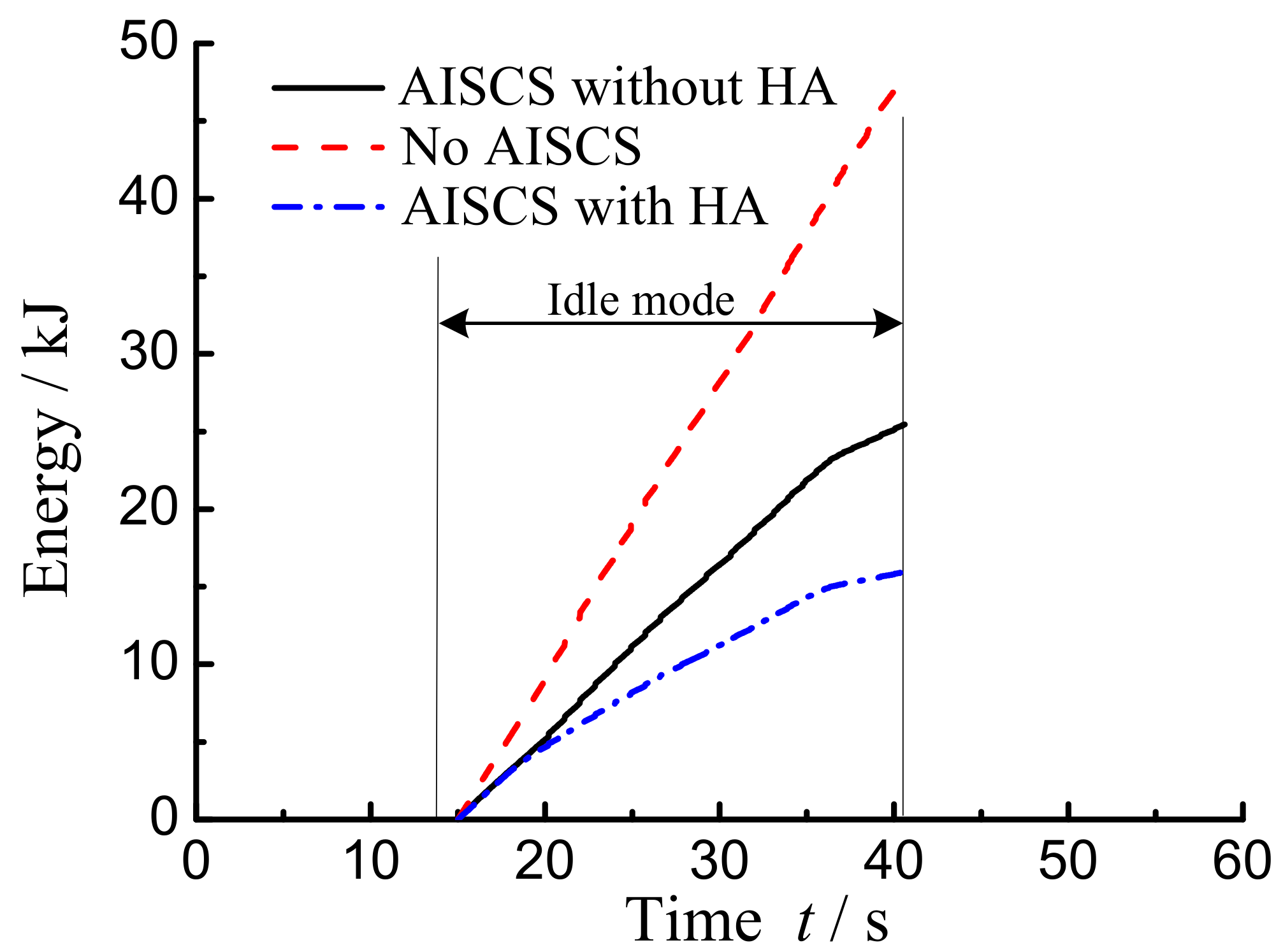
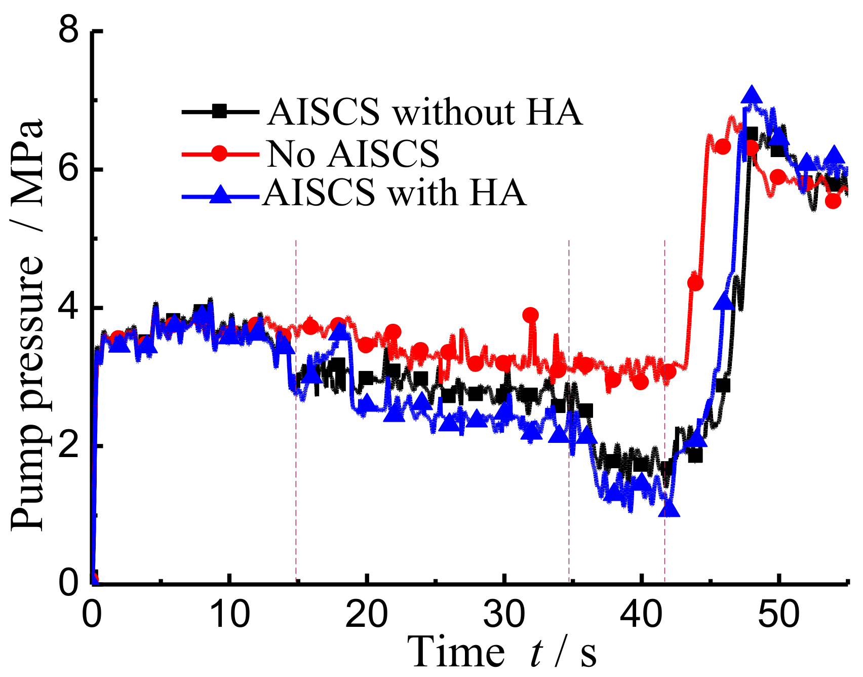
The AISCS with and without the HA has some influence on the energy consumption. Seen from Figure 8 and Figure 9, only at the time from 15 s to 17.6 s, the output pressure of the pump in AISCS with HA is more high than that in the traditional AISCS, because the pump consumes more energy to charge the HA at this process. However, both the EM speed and the output pressure of the pump in the idle time is less than the other systems, which means that the energy consumption of the pump can be reduced in the proposed system. It can be seen from Table 2 and Figure 10 that during the idle mode, including the first level and second level idle mode, the system without the AISCS consumes 48.23 kJ energy, the AISCS without the HA consumes 30.07 kJ energy, and the proposed AISCS with the HA consumes 25.46 kJ energy. When compared with the system without AISCS, the energy-saving efficiency of the system with the HA is 67% and that without the HA is 47%, which means that the proposed AISCS can both improve the energy saving and control performance than the traditional AISCS.
5. Summary and Conclusions
According to the working cycle and the characteristics of the traditional AISCS of construction machinery, a novel two-level AISCS with the HA is proposed. Some useful conclusions are obtained, as follows.
- The proposed AISCS can realize the EM speed switching among the first level idle speed, second level idle speed, and normal speed based on the control strategy. The idle speed can set to a low value, which is 500 rpm in the proposed AISCS to reduce the energy consumption.
- The proposed AISCS with the HA can build up the load pressure quickly and make the load follow the action of the joystick rapidly when the idle mode is cancelled. This can make the actuator move more stably and smoothly.
The proposed AISCS with the HA can save 67% energy than the system without AISCS and can improve the energy saving and control performance than the traditional AISCS.
Acknowledgments
The authors acknowledge the support of National Natural Science Foundation of China (51505160), China Postdoctoral Science Foundation (2017M612139), Industry Cooperation of Major Science and Technology Project (2017H6013), Natural Science Foundation of Fujian Province (2017J01087) and Open Foundation of the State Key Laboratory of Fluid Power and Mechatronic Systems (GZKF-201611).
Author Contributions
H.R. proposed the idea of the proposed AISCS. T.L. improved the schematic of the novel AISCS. S.Z. set up the model and tested the motor used in the test. W.H. did the experiment and made the control strategy. C.M. analyzed the data. T.L. and H.L. wrote the paper.
Conflicts of Interest
The authors declare no conflicts of interest.
Abbreviations
| EM | Electric motor |
| HA | Hydraulic accumulator |
| HE | Hydraulic excavator |
| AISCS | Automatic idle speed control system |
| CNG | Compressed natural gas |
| PWM | Pulse-width modulation |
Nomenclature
| AL | effective area of drive chamber of the cylinder |
| Cep | external leakage coefficient of the pump |
| Cip | internal leakage coefficient of the pump |
| k | proportionality coefficient between the target velocity and the joystick pressure |
| np | speed of the pump |
| n | polytrophic exponent |
| pa0 | pre-charge pressure of the HA |
| pa1 | minimum working pressure of HA |
| pa2 | maximum working pressure of HA |
| pau | upper limited pressure of the HA |
| pax | working pressure of the HA |
| pjL | left side output pressure of the joystick |
| pjR | right side output pressure of the joystick |
| ∆pj | pressure differential of the two sides of the joystick |
| pL | load pressure |
| pLb | non-rod chamber pressure of the actuator |
| pLs | rod chamber pressure of the actuator |
| pLmax | maximum pressure of the load |
| ∆pac | Preset pressure differential of HA |
| pp | output port pressure of the pump |
| ∆p | the pressure differential between the HA and the load |
| ∆pvalve | pressure drop across the solenoid directional valve 1, multi-way valve and oil pipes |
| Qac | flow rate of the HA |
| qp | displacement of the pump |
| t | time |
| T1 | time that the system stay at the first level idle speed |
| T2 | time that the system stay at the second level idle speed |
| V0 | gas volume under the pressure p a0 of the HA |
| ∆V | volume change of the HA |
| v | actual velocity of the load |
| vt | target velocity of the load |
| vtmax | maximum target velocity of the actuator |
| δ | a small positive value |
| ηc | volumetric efficiency of the pump |
References
- Chen, Q.; Wu, W.; Liu, W.; Zhang, X. Research on pump control signal of excavator positive control system. J. Hefei Univ. Technol. 2014, 37, 645–649. [Google Scholar]
- Cheng, M.; Xu, B.; Yang, H. Efficiency Improvement for Electrohydraulic Flow Sharing Systems. In Proceedings of the 9th International Fluid Power Conference, RWTH Aachen University, Aachen, Germany, 24–26 March 2014. [Google Scholar]
- Sugimura, K.; Murrenhoff, H. Hybrid Load Sensing—Displacement Controlled Architecture for Excavators. In Proceedings of the 14th Scandinavian International Conference on Fluid Power (SICFP'15), Tampere University of Technology, Tampere, Finland, 20–22 May 2015; pp. 20–22. [Google Scholar]
- Jackson, R.S.; Clanton, R.R.; Pfaff, J.L. Hydraulic Control Valve System with Electronic Load Sense Control, U.S. Patent 7,089,733, 15 August 2006. [Google Scholar]
- Lin, T.; Wang, Q.; Hu, B.; Gong, W. Development of hybrid powered hydraulic construction machinery. Autom. Constr. 2010, 19, 11–19. [Google Scholar] [CrossRef]
- Hippalgaonkar, R.; Ivantysynova, M.; Zimmerman, J. Fuel savings of a mini-excavator through a hydraulic hybrid displacement controlled system. In Proceedings of the 8th International Fluid Power Conference, Dresden, Germany, 26–28 March 2012; pp. 139–153. [Google Scholar]
- Montazeri-Gh, M.; Poursamad, A.; Ghalichi, B. Application of genetic algorithm for optimization of control strategy in parallel hybrid electric vehicles. J. Frankl. Inst. 2006, 343, 420–435. [Google Scholar] [CrossRef]
- Cipek, M.; Pavković, D.; Petrić, J. A control-oriented simulation model of a power-split hybrid electric vehicle. Appl. Energy 2013, 101, 121–133. [Google Scholar] [CrossRef]
- Wang, T.; Wang, Q. Optimization design of a permanent magnet synchronous generator for a potential energy recovery system. IEEE Trans. Energy Convers. 2012, 27, 856–863. [Google Scholar] [CrossRef]
- Wang, T.; Wang, Q.; Lin, T. Improvement of boom control performance for hybrid hydraulic excavator with potential energy recovery. Autom. Constr. 2013, 30, 161–169. [Google Scholar] [CrossRef]
- Minav, T.A.; Virtanen, A.; Laurila, L.; Pyrhönena, J. Storage of energy recovered from an industrial forklift. Autom. Constr. 2012, 22, 506–515. [Google Scholar] [CrossRef]
- Lin, T.; Wang, Q.; Hu, B.; Gong, W. Research on the energy regeneration systems for hybrid hydraulic excavators. Autom. Constr. 2010, 19, 1016–1026. [Google Scholar] [CrossRef]
- Cairano, S.D.; Yanakiev, D.; Bemporad, A.; Kolmanovsky, L.V.; Hrovat, D. Model predictive idle speed control: Design, analysis, and experimental evaluation. IEEE Trans. Control Syst. Technol. 2012, 20, 84–97. [Google Scholar]
- He, Y.; Ma, F.; Deng, J.; Shaoa, Y.; Jian, X. Reducing the idle speed of an SI CNG engine fueled by HCNG with high hydrogen ratio. Int. J. Hydrog. Energy 2012, 37, 8698–8703. [Google Scholar] [CrossRef]
- Li, X.; Yurkovich, S. Sliding mode control of delayed systems with application to engine idle speed control. IEEE Trans. Control Syst. Technol. 2001, 9, 802–810. [Google Scholar]
- Hrovat, D.; Sun, J. Models and control methodologies for IC engine idle speed control design. Control Eng. Pract. 1997, 5, 1093–1100. [Google Scholar] [CrossRef]
- Huang, X.; Xie, H.; Song, K. Idle speed control of FSAE racing engines based on Mid-ranging ADRC. In Proceedings of the 33rd Chinese Control Conference (CCC), Nanjing, China, 28–30 July 2014; pp. 201–206. [Google Scholar]
- Chien, T.L.; Chen, C.C.; Hsu, C.Y. Tracking control of nonlinear automobile idle-speed time-delay system via differential geometry approach. J. Frankl. Inst. 2005, 342, 760–775. [Google Scholar] [CrossRef]
- Kandler, C.; Koenings, T.; Ding, S.X.; Weinhold, N.; Schultalbers, M. Stability Investigation of an Idle Speed Control Loop for a Hybrid Electric Vehicle. IEEE Trans. Control Syst. Technol. 2015, 23, 1189–1196. [Google Scholar] [CrossRef]
- Laurain, T.; Lauber, J.; Palhares, R.M. Observer design to control individual cylinder spark advance for idle speed management of a SI engine. In Proceedings of the IEEE International Conference on Industrial Electronics and Applications (ICIEA), Auckland, New Zealand, 15–17 June 2015; pp. 262–267. [Google Scholar]
- Chen, T.; Xie, H.; Li, L.; Zhang, L.; Wang, X.; Zhao, H. Methods to achieve HCCI/CAI combustion at idle operation in a 4VVAS gasoline engine. Appl. Energy 2014, 116, 41–51. [Google Scholar] [CrossRef]
- Xiong, Y.; Zhang, P.; Guo, S. Control and experiment research of XR220D rotary drilling Rig. Equip. Manuf. Technol. 2015, 81, 240–241. [Google Scholar]
- Liu, R. Research on the power matching control system for the hydraulic excavators. Mach. Tool Hydraul. 2015, 43, 111–115. [Google Scholar]
- Hao, P.; He, Q.; Zhang, X.; Xie, S. Study on Load and Operating Mode Identification of Excavator. Hydraul. Pneum. Seals 2008, 5. Available online: http://en.cnki.com.cn/Article_en/CJFDTotal-YYQD200805005.htm (accessed on 23 March 2018).
Figure 1.
Schematic of the traditional automatic idle speed control system (AISCS).
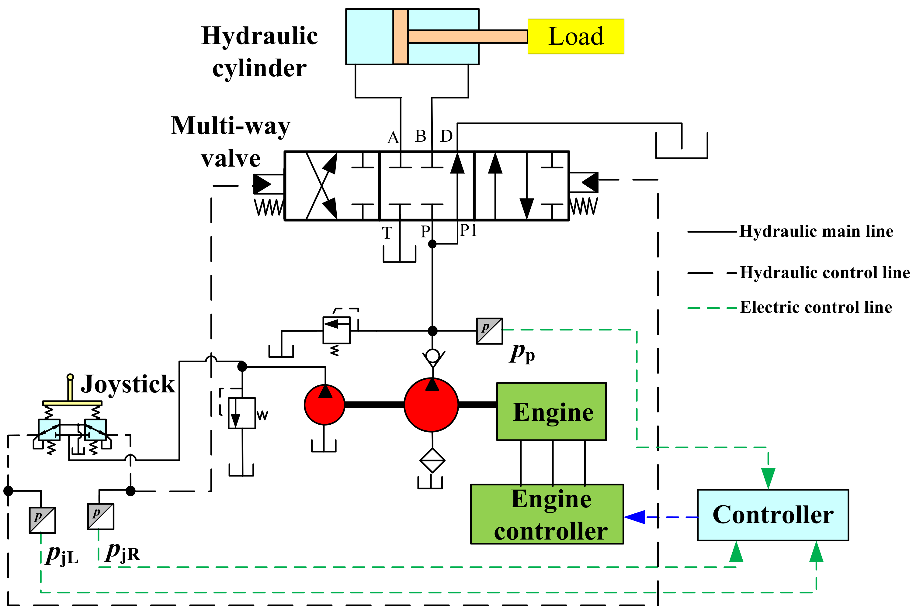
Figure 2.
Schematic of the novel AISCS.

Figure 3.
Overall control diagram of the AISCS.
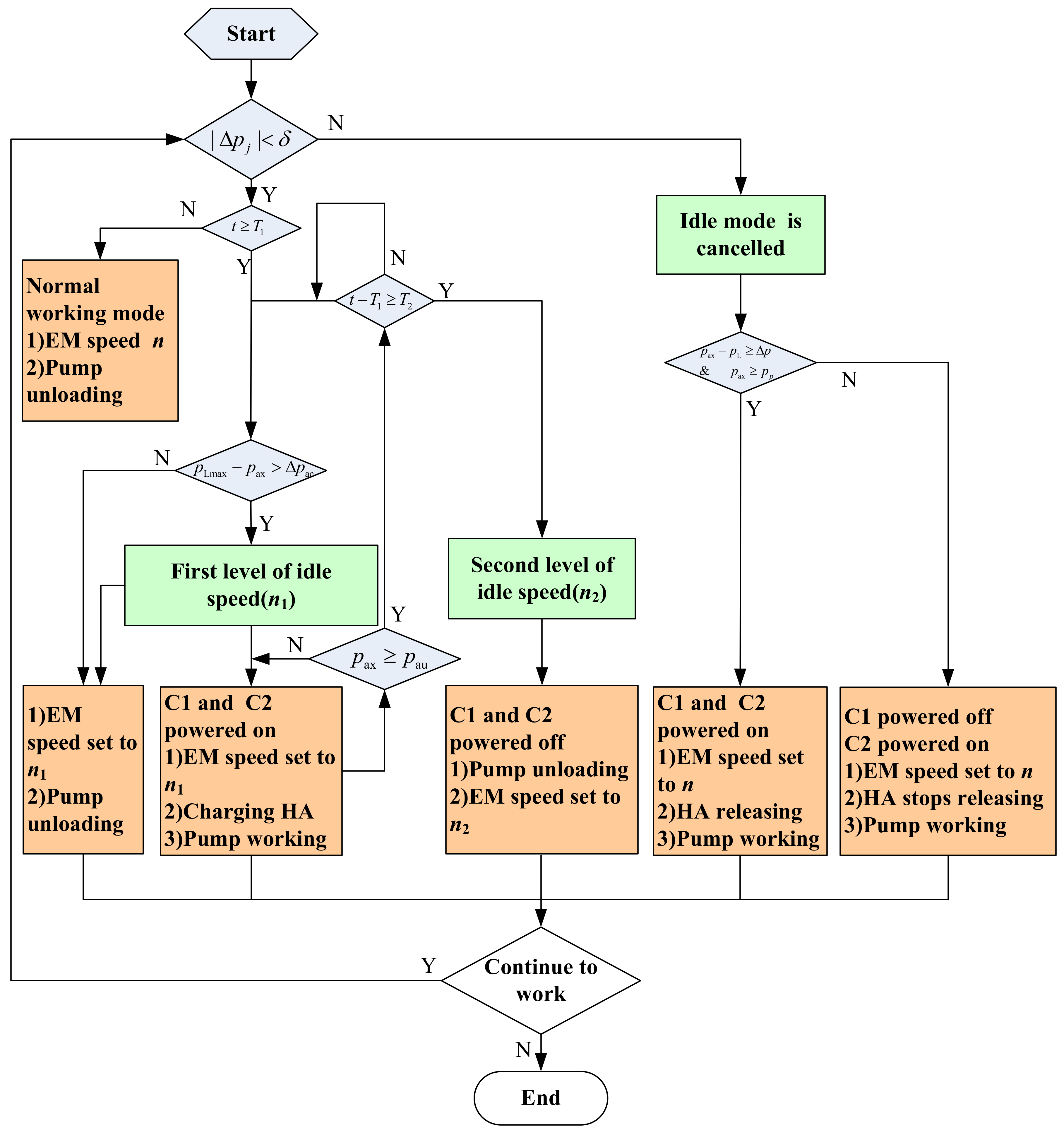
Figure 4.
Layout of the test rig.

Figure 5.
Experimental curves of the electric motor (EM) speed and joystick pressure.
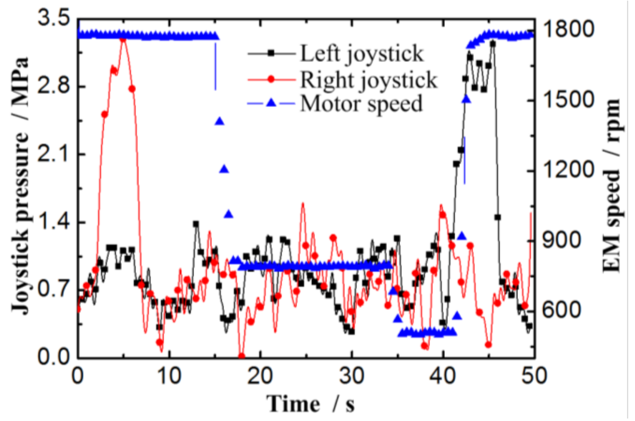
Figure 6.
Pressures during the proposed AISCS process.
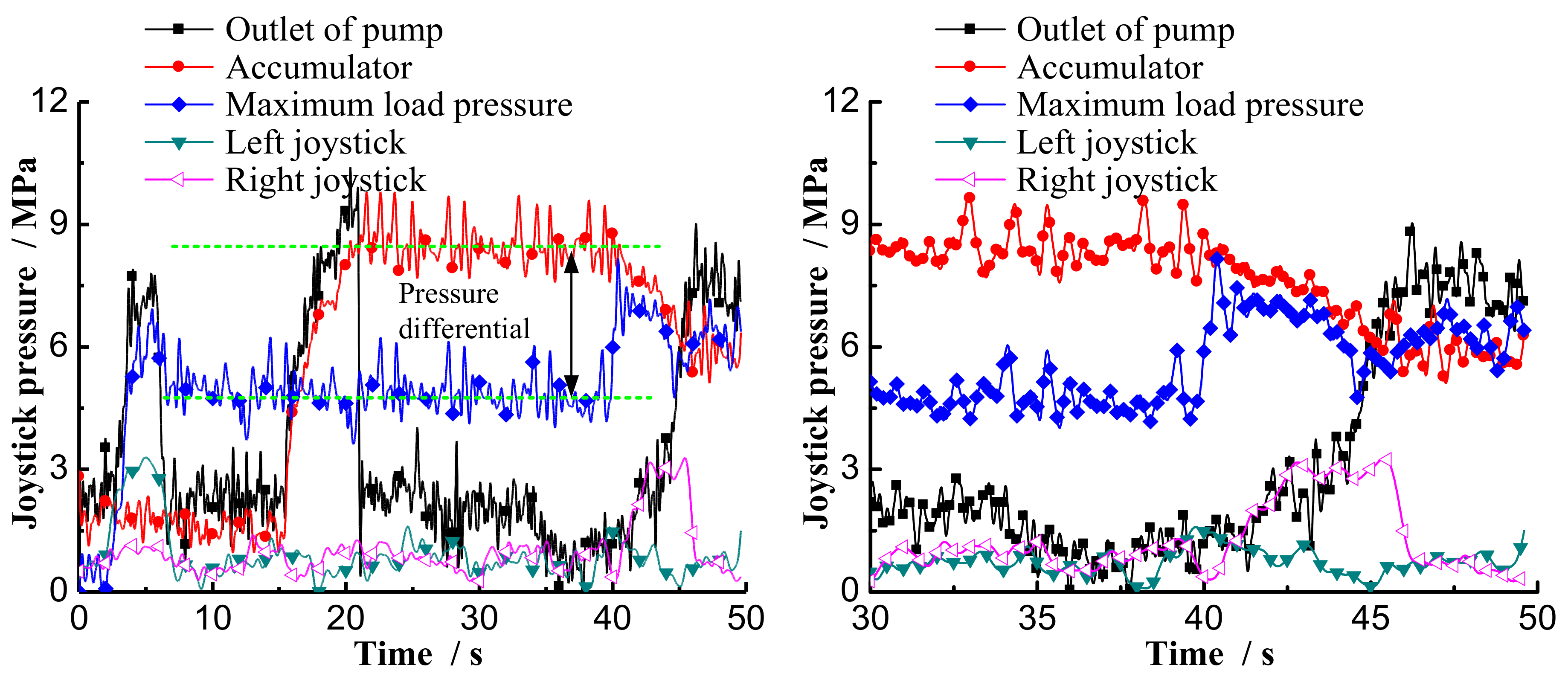
Figure 7.
Pressures of the non-rod chamber of the actuator cylinder under different pressure differential.
Figure 7.
Pressures of the non-rod chamber of the actuator cylinder under different pressure differential.

Figure 8.
EM speed comparison under different control system.
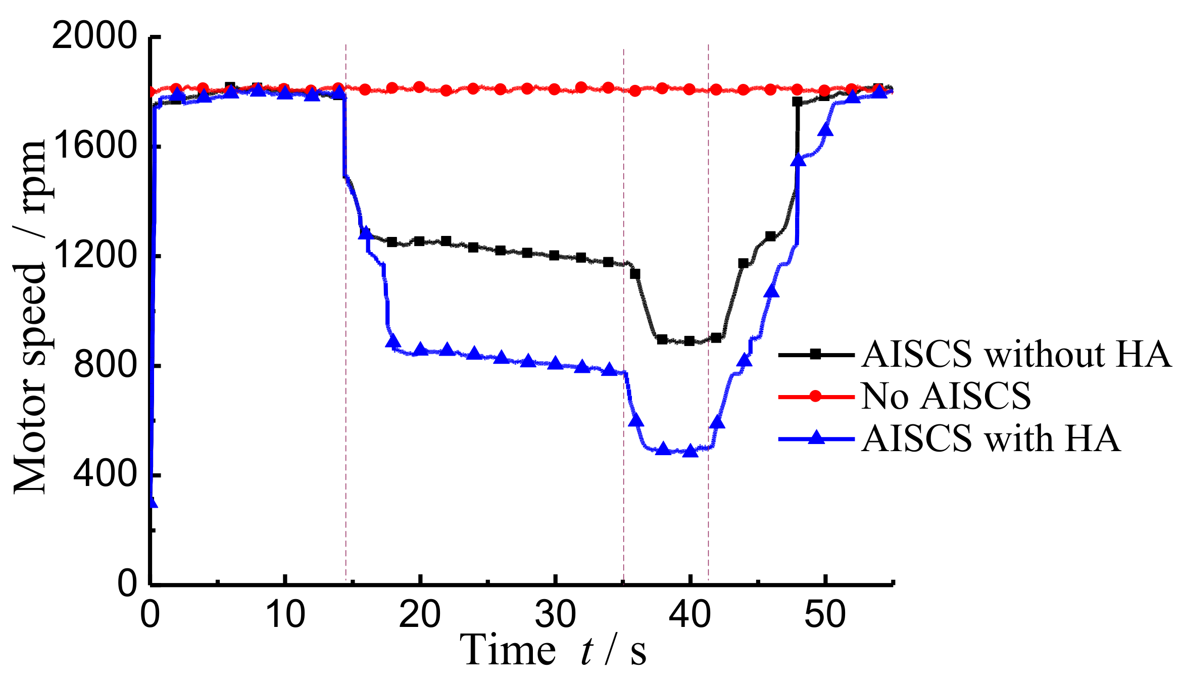
Figure 9.
Pump pressure comparison under different control system.

Figure 10.
Energy consumption comparison in idle time under different control system.

Table 1.
Key parameters used in the test rig.
| Key Components | Parameter | Value |
|---|---|---|
| Actuator | Rod diameter/mm | 35 |
| Cylinder diameter/mm | 63 | |
| Maximum stroke/mm | 100 | |
| Electric motor | Power/kW | 8 |
| Rated speed/(rpm) | 1800 | |
| Pump | Displacement/(mL·r−1) | 16 |
| Hydraulic accumulator | Volume/L | 1.6 |
| Pre-charge pressure/MPa | 2 |
Table 2.
Energy saving in different system.
| System Type | Energy Consumed | Energy Efficiency |
|---|---|---|
| No idle speed control | 48,233 J | - |
| AISCS with HA | 15,950 J | 67% |
| AISCS without HA | 25,459 J | 47% |
© 2018 by the authors. Licensee MDPI, Basel, Switzerland. This article is an open access article distributed under the terms and conditions of the Creative Commons Attribution (CC BY) license (http://creativecommons.org/licenses/by/4.0/).
Share and Cite
MDPI and ACS Style
Ren, H.; Lin, T.; Zhou, S.; Huang, W.; Miao, C. Novel Automatic Idle Speed Control System with Hydraulic Accumulator and Control Strategy for Construction Machinery. Appl. Sci. 2018, 8, 496. https://doi.org/10.3390/app8040496
AMA Style
Ren H, Lin T, Zhou S, Huang W, Miao C. Novel Automatic Idle Speed Control System with Hydraulic Accumulator and Control Strategy for Construction Machinery. Applied Sciences. 2018; 8(4):496. https://doi.org/10.3390/app8040496
Chicago/Turabian StyleRen, Haoling, Tianliang Lin, Shengyan Zhou, Weiping Huang, and Cheng Miao. 2018. "Novel Automatic Idle Speed Control System with Hydraulic Accumulator and Control Strategy for Construction Machinery" Applied Sciences 8, no. 4: 496. https://doi.org/10.3390/app8040496
Note that from the first issue of 2016, this journal uses article numbers instead of page numbers. See further details here.