Numerical Analysis to Improve the Ballistic Trajectory of an Air-Based Material Density Separator System
by
 ,
,
Haider Ali
1 ,
,
Kyung Won Kim
1,
Sung Gi Bang
2,
Hyun Bae Chae
2,
Seung Wook Shin
2 and
Cheol Woo Park
1,* 1
School of Mechanical Engineering, Kyungpook National University, 80 Daehakro, Bukgu, Daegu 41566, Korea
2
I-ENTEC Co. Ltd., 18-Gil 33, Seongseogongdanbukro, Dalseogu, Daegu 42712, Korea
*
Author to whom correspondence should be addressed.
Appl. Sci. 2018, 8(3), 359; https://doi.org/10.3390/app8030359
Submission received: 2 February 2018
/
Revised: 23 February 2018
/
Accepted: 27 February 2018
/
Published: 1 March 2018
(This article belongs to the Section Mechanical Engineering)
Abstract
:A material density separator utilizes a high velocity channel of air with a ballistic trajectory to separate materials based on their different densities and sizes. Light materials are carried with the airflow, leaving behind the separated heavy materials. A vibrating bed is then used to collect both heavy and light plastic materials for further separation and recycling processes. The effectiveness of the separation process mainly depends on the ballistic trajectory of the air stream and the slanting position of the vibrating bed. In this study, flow characteristics inside the density separation system were investigated to optimize the ballistic trajectory of air and the slanting position of the vibrating bed to improve the separation process. Various inlet air velocities, duct shapes, and the slanting angles of the mechanical separators were used to study their effects on flow properties (velocity magnitude, pressure, shear stress, and vorticity). Results show that the ballistic trajectory of air strongly depends on the diameter and shape of the duct hole, the inclination angle of the vibrating bed, and the air inlet velocity. The selection of the suitable values of these parameters is necessary to improve the plastic separation process.
1. Introduction
Plastics have become indispensable materials in modern life because of their versatility, lightweight, durability, strength, and relatively low cost. A dramatic increase in plastic production has been observed in recent years [1,2]. Regardless of high consumption, a large portion of produced plastic ends up as solid waste that can pose a serious threat to the environment. The increase in solid waste also increases the disposal problem, because the majority of this plastic waste is not biodegradable. Therefore, waste management is necessary for the handling and disposal process [3,4,5]. Plastic recycling is one of the most attractive waste management methods, because the plastic material can be melted and reprocessed without changing the physical and chemical properties. With the space available for landfills continuously reducing, plastic recycling is receiving more attention because of its cost effectiveness and its lesser effect on the environment [6,7,8]. However, prior to the recycling process, different types of plastic must be separated from each other based on chemical structure. The cross-contamination of plastics with different chemical structures at different melting points can render the reprocessed plastic unusable by affecting its quality [9,10]. Numerous separation methods have been developed previously, because of the difficulties in the separation of plastics from one another [1]. Triboelectrostatic, density-based, and forth flotation processes are several well-known separation methods utilized for the plastic recycling process. The triboelectrostatic method separates the materials based on the difference of their electrical conductivities [11,12]. This method successfully separates polyvinyl chloride (PVC) and polyethylene terephthalate (PET) but is less efficient, with low output under working conditions. The presence of labels and coating on the materials reduces the separation process, because the triboelectric probe fails to sense the material type [13,14]. The forth flotation process is another separation method that utilizes the difference in surface properties of different plastics [15,16]. This method involves two processes, i.e., the treatment of plastic materials with an alkaline solution and then the carrying out of the froth flotation process. However, the flotation method is only suitable for small PVC and PET particles (less than 10 mm). Therefore, as a preliminary step, particles size reduction and the sizing of plastic waste is required, which makes this method the most expensive and complex among all the separation processes [17,18].
Density separation is the most flexible and widely used industrial separation process because of its cost-effectiveness and high capacity for recycling plastic waste. This method is used to remove dirt, stones, and metals and to separate different types of plastics based on difference in densities. The density separation is the most widely used separation process because of its ability to separate all types of industrial material [19,20,21]. Density separation can be processed with a variety of working solutions, such as dry or air-based particles (air tables or zigzag air classifiers), water-based solutions, and suspensions (separating medias) [17,19]. The plastic material sinks or floats in a fluid; therefore, the hydrodynamics and plastic material size significantly affect the density separation process [19,22,23]. Dry or air-based separation methods reportedly require close sizing of plastic waste materials to achieve reasonable separating results [19]. Air-based separation is widely used in the dry beneficiation of coal, because wet processing requires a significant amount of water [24,25,26]. Air-based density separators use the kinetic energy of a high air stream with a ballistic trajectory to separate plastic wastes based on the difference in grain shape and size. Heavy plastic materials fall downward on the vibrating bed because of gravity, whereas lighter materials are carried away with the air stream and are delivered upward on the vibrating bed. The vibrating bed possesses a perforated structure, which further separates plastic waste that is then carried to the recycling process. The combination of the vibrating bed inclination, the adjustment of the vibration parameters, and the ballistic trajectory of air can be used to achieve high-quality separation [26,27]. However, the experimental work on air-based density separators for plastic waste recycling is limited because of the immense expenditure involved in the manufacture and operation of the equipment. Therefore, a numerical study that computes flow properties in the air-based density separator is required to optimize the ballistic trajectory of air and the slanted position of the vibrating bed [26,27].
The present study primarily addresses flow characteristics in an air-based density separator to optimize the separation process. The density separator utilizes a high-velocity air channel with a ballistic trajectory to separate PVC (vinyl) and PET (bottles) materials for recycling. In this study, a duct with different hole diameters and shapes was installed at the upper wall of the density separator to release the excessive kinetic energy and improve the air ballistic trajectory. We consider a 2D model of the density separator to optimize the air ballistic trajectory and the slanted position of the vibrating bed by computing flow properties. Various inlet air velocities, duct hole diameters and shapes, and slanting angles of the vibrating bed were used to study their effects on the velocity magnitude, pressure distribution, shear stress, and vorticity magnitude. The effects of the interaction between flow and plastic waste are outside the scope of this study and thus were not considered. The separation process in the air-based density separator was described by using the aforementioned fluid dynamic properties, and plastic waste was not considered physically [26,27].
2. Materials and Methods
Mathematical Modeling and Implementation
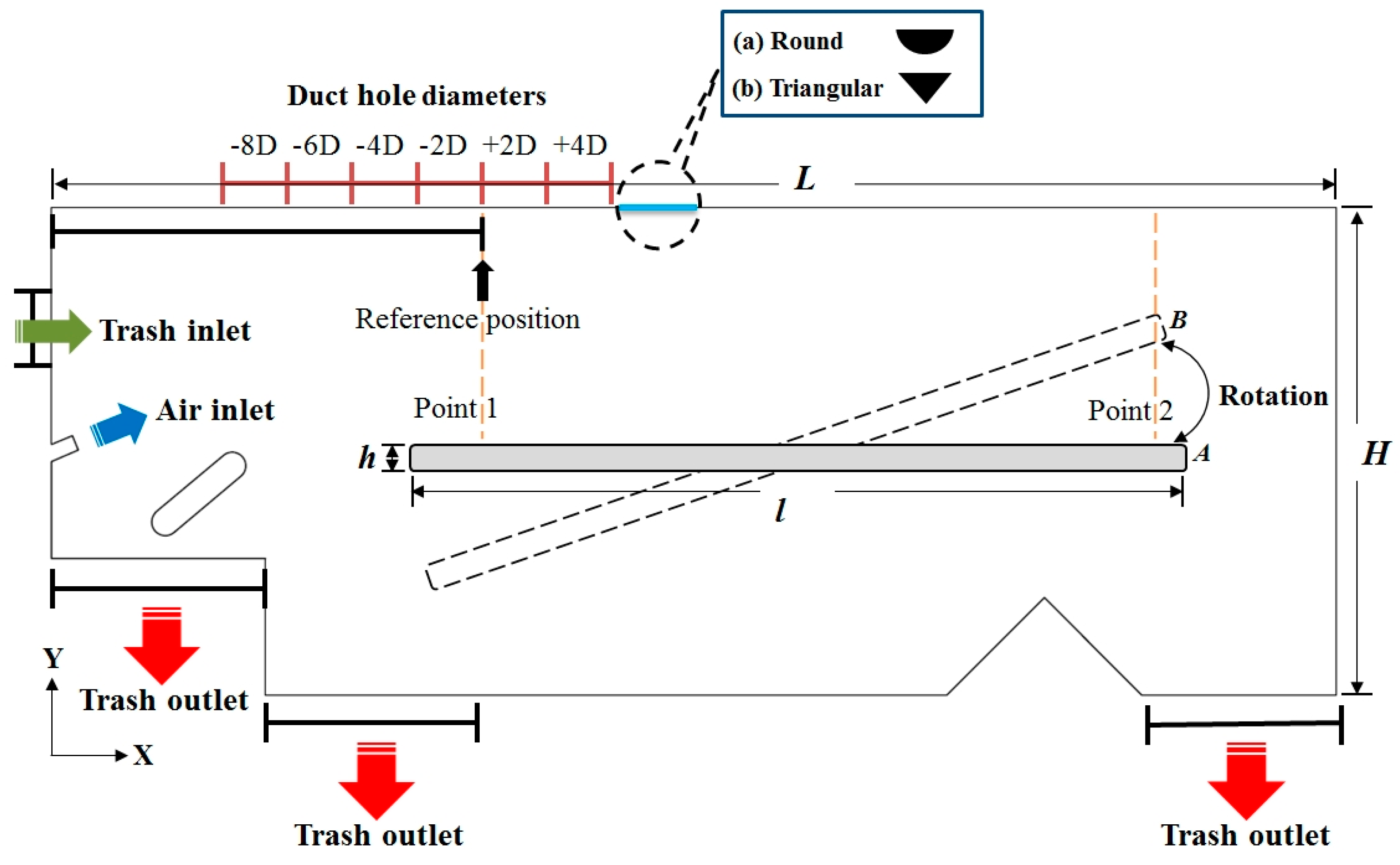
A 2D computational model of an air-based density separator with a length () of 6.6 m and a height () of 2.5 m is presented in Figure 1. The vibrating bed is 4 m in length () and 2.5 m in height (). The total angular rotation of the vibrating bed is 8° from the initial position A (θ = 0°) to the final position B (θ = 8°). This angular rotation improves the recycling process by increasing the distribution of separated plastic waste from the vibrating bed to the trash outlet. A small guide is also placed near the air inlet at an angle of 60° for directing the heavier PET materials, which fails with the air stream to the vibrating bed, to trash outlet.
The airflow in the density separator was turbulent, with a high Reynolds number of 60,100 at an inlet air velocity of 35 m/s. Turbulence was modeled by the Reynolds averaged Navier-Stokes (RANS) equations, because the description of the flow at all points in time and space is not practical. The RANS equations contain the weight of all turbulent flow vortices and denote the equations for average flow magnitudes. This representation is valuable because of its modification of every quantity in space and time once turbulence is attained by the fluid. The governing equations of RANS are as follows:
in which , represent the density (kg/m3) and kinematic viscosity (Pa·s) of air, is the average velocity (m/s), is the velocity fluctuation (m/s), and denotes pressure (Pa).
The k–ε turbulence model was used to treat turbulent flow with high Reynolds number in the density separator. This turbulence model is suitable for complex flow patterns, as the model produces reasonable and stable results with less computational time [28]. The governing equations of turbulent kinetic energy () and dissipation rate (ε) for the k–ε turbulence model are as follows:
in which and are the turbulent Prandtl number for kinetic energy and the dissipation rate, respectively, and and are the first and second experimental model constants for the dissipation rate, respectively. In the present study, we assigned the following values to the above-mentioned constants: = 1.0, = 1.3, = 1.44, = 1.92, and = 0.09. Turbulent or eddy viscosity (), which is defined by the k–ε turbulence model, is given as follows:
in which is the turbulent viscosity (Pa·s), ε is the turbulent dissipation rate (m2/s3), represents the turbulent kinetic energy (m2/s2), is the air density (kg/m3), and is the model constant.
The present study selected several parameters (air duct hole diameter, air duct hole shape, bed slanting angle, and air inlet velocities) to analyze their influence on separation process because of their significant effect on the air ballistic trajectory of the density separator [26,27]. All the geometrical dimensions (air duct hole diameter and air duct hole shape) and boundary conditions (bed slanting angle and air inlet velocities) in this study were selected based on the actual flow conditions of the air-based density separator. Moreover, this study used arbitrary values of these parameters to analyze their effect on the flow characteristics of the density separator. This approach helps to select the suitable values of these parameters to improve the air ballistic trajectory and consequently enhance the separation process. The air inlet was assigned with an initial inlet velocity of 35 m/s, and the trash outlet boundaries were maintained under atmospheric pressure conditions. A duct was installed on the upper boundary of the basic separator model to release the extra pressure and improve the ballistic trajectory of the air stream. Duct hole size or diameter was varied according to the air inlet channel diameter (). The positive and negative signs present with the duct hole diameters represent the respective location of duct hole from the reference position (Figure 1). Positive signs show the increase in duct hole diameter toward the right side of the reference position and vice versa. Furthermore, two different duct shapes (i.e., round and triangular) were used to see the effects of duct shape on ballistic trajectory for separation improvement. The vibrating bed was assigned with slanting angles (θ) from 0° to 8°. Inlet velocities were varied from 30 to 45 m/s to observe the effect on the flow characteristics in the density separator. Two points in the radial direction (point 1 and 2) were selected on the vibrating bed for the computation of flow properties (Figure 1).
A commercial code COMSOL-Multiphysics (V 5.3a) was used to optimize the separation process by computing flow properties in the air-based density separator. A steady state solver is employed to simulate the k–ε turbulence model. All computations were performed on an Intel Core i7-3370 3.90 GHz processor with a 16 GB RAM operating system. The air-based density separator models are discretized by using a free triangular mesh type with 147,547 interior elements and 1717 boundary elements (extra fine mesh), respectively.
3. Results and Discussion
3.1. Methodology Validation and Grid Refinement Study
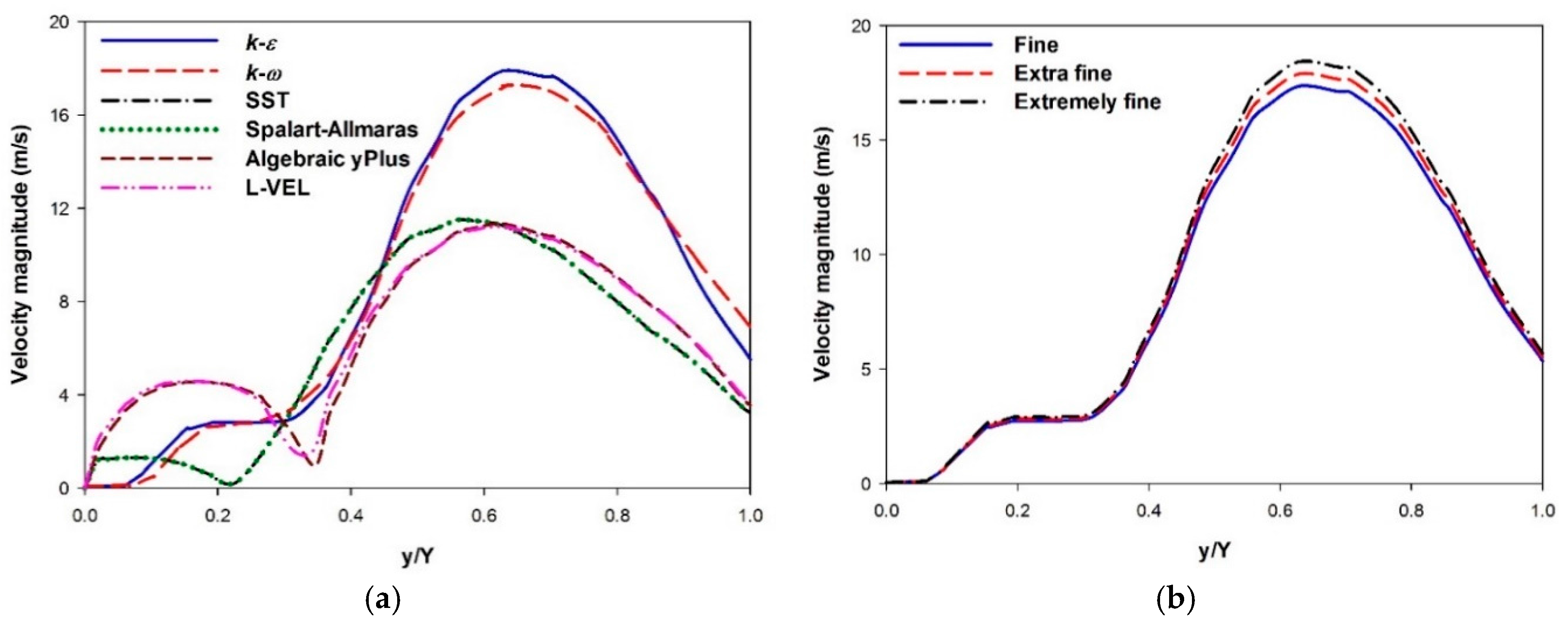
The employed turbulence analysis method (k–ε) and the results were compared and verified with the different turbulent schemes. Figure 2a illustrates the velocity magnitude in the +4D separator model for the different turbulence models. The results were computed at point 1 using an air inlet velocity of 35 m/s and bed slanting angle (θ) of 0°. The k–ε and the k–ω models resulted in higher velocity magnitudes than other turbulence models. The Spalart-Allmaras and the shear stress transport (SST) models do not use any wall functions and tend to be most accurate when solving the flow near the wall. Thus, these two models do not accurately compute flow fields away from the walls especially for the shear flow, separated flow, or decaying turbulence, and they also require high mesh resolution near the wall [29]. The algebraic yPlus and L-VEL are algebraic turbulence models based on the distance to the nearest wall. These two turbulence models are robust and computationally inexpensive but also least accurate, because they do not solve any additional transport equations. The algebraic yPlus and L-VEL models provide good approximations for internal flow with low Reynolds number. Therefore, these models failed to precisely predict the flow in the density separator because of high Reynolds number (60,100). The standard k–ε is very popular for industrial applications (complex geometries) due to its good convergence rate and relatively low memory requirements. The k–ω model has more memory requirements and is useful in many cases in which the k–ε model is not accurate. A reasonable agreement was found between the standard k–ε and the k–ω models, thus verifying the proposed turbulence method (k–ε) for the separation process in the material density separator [28].
Grid refinement study was performed to test the accuracy of the results and to ensure that the velocity magnitude did not change with mesh size (Figure 2b). The study adopted different mesh refinements by varying them with a factor of five: fine (29,509 domains and 352 boundary elements), extra fine (147,547 domains and 1717 boundary elements), and extremely fine (737,740 domains and 8585 boundary elements). The results were computed in the +4D separator model using an air inlet velocity of 35 m/s and bed slanting angle (θ) of 0°. A minimal difference was observed between the velocity magnitudes at point 1 for different mesh refinements. Thus, all the separator models were simulated using the extra fine (147,547 domains and 1717 boundary elements) mesh refinement.
3.2. Air Duct Hole Diameter
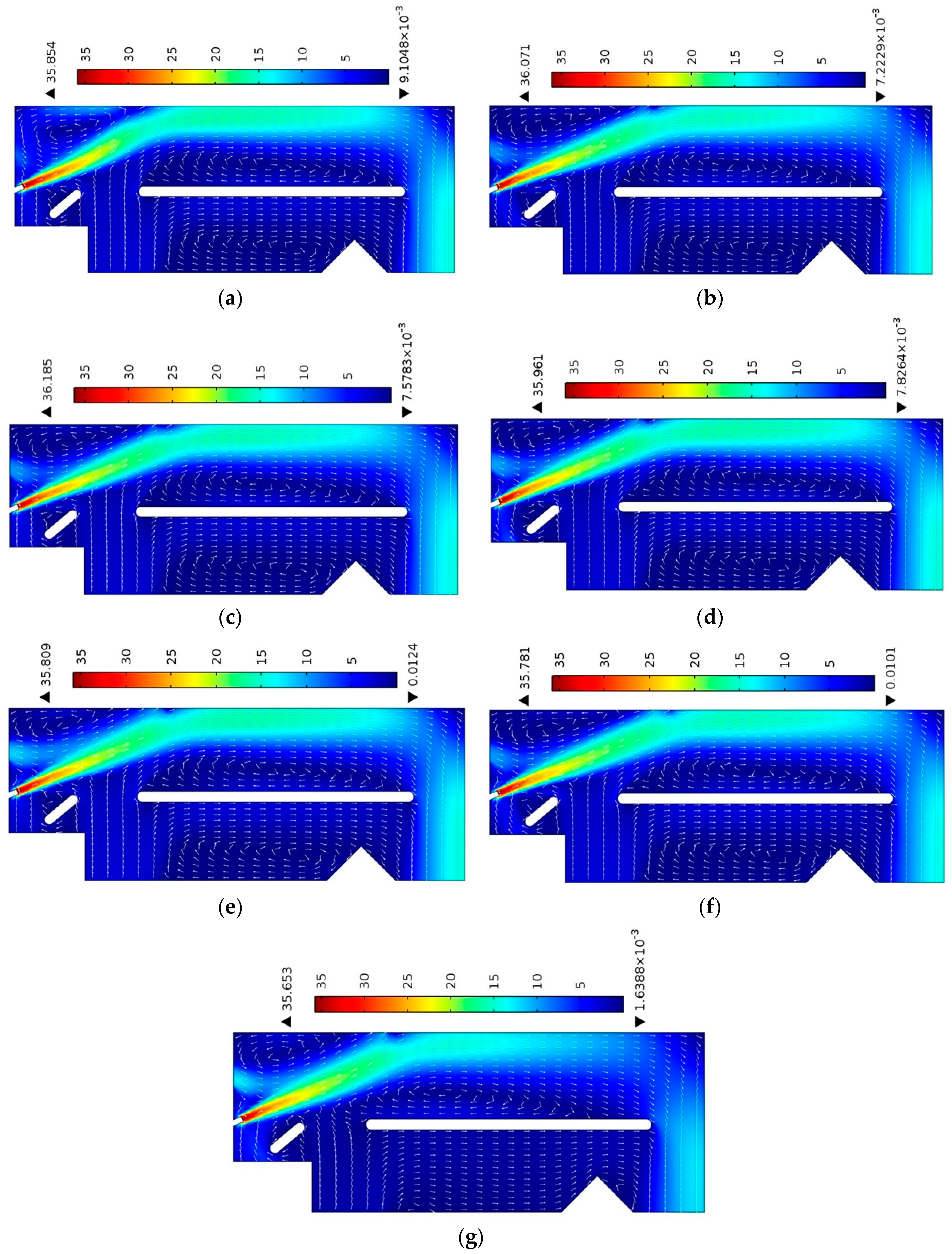
Contour and arrow plots in the air density separator were plotted to investigate the effect of the duct hole diameter on the separation process of the plastics. As Figure 3 shows, airflow particles move with a ballistic trajectory from the air inlet to the trash outlet. Recirculation zones formed on the vibrating bed, because the minimum flow is essential for the separation process, as the plastic material is collected in this region [23]. The introduction of duct hole at the upper wall of the density separator has clearly improved the ballistic trajectory of the air stream. Increasing the air duct hole diameter in the positive direction from the reference position increased the velocity magnitude. By contrast, increasing the air duct hole diameter in the negative direction reduced the velocity magnitude. Light plastic materials (PVC) are easily carried away with higher velocity magnitude and are fed upward on the vibrating bed, which in turn improves the separation process. Heavier PET materials fall on the small guide, which directs the materials to the outlet for recycling. Separation process is less effective when the air ballistic trajectory does not possess higher kinetic energy (velocity magnitude). Therefore, density separation cannot easily separate PET and PVC materials from each other. Moreover, the +4D separator model exhibited higher velocity magnitudes than other models (Figure 3c). These results show that increasing the duct hole diameter in the positive direction enhanced separation. Moreover, the results indicate that the +4D separator model is more suitable for separating the PET and PVC material because of the higher velocity magnitude.
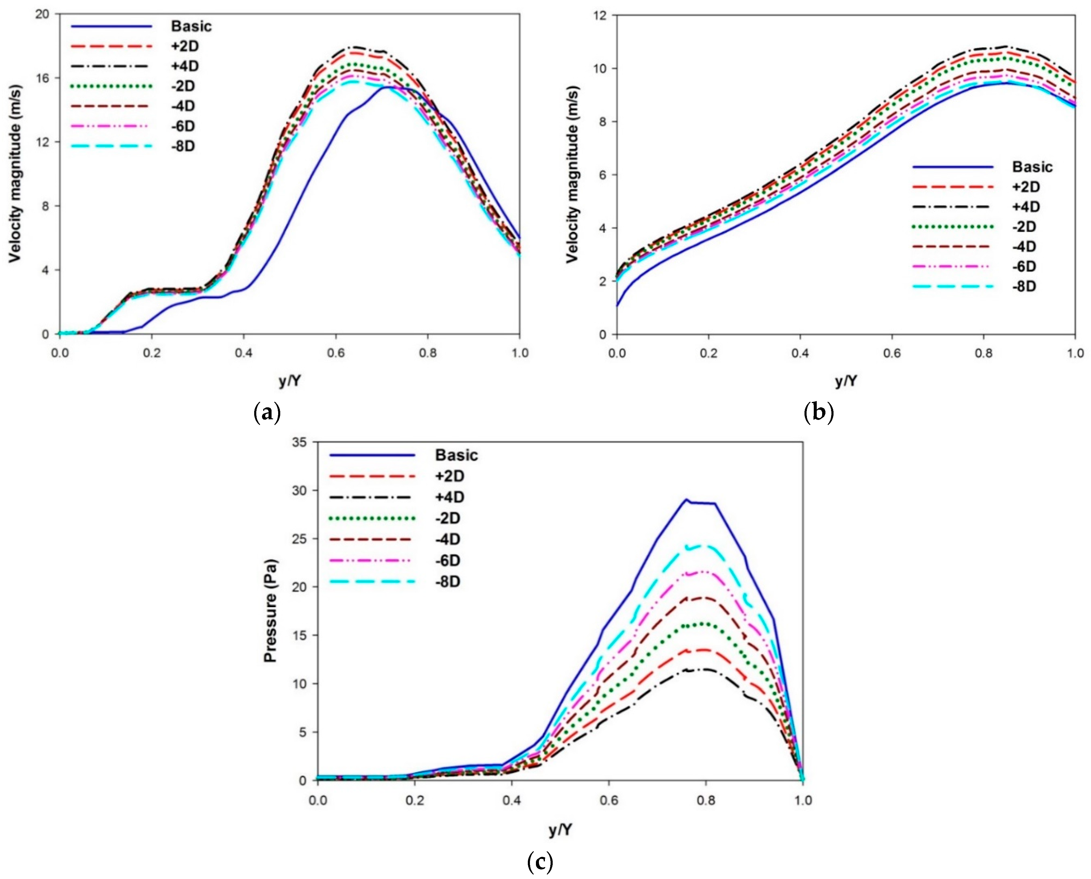
The kinetic energy (velocity magnitude) of the ballistic trajectory significantly varies at the leading and trailing edges of the vibrating bed (Figure 3). Therefore, two points have been selected at the vibrating bed to estimate flow properties. The effect of air duct hole diameter was further investigated by computing the velocity and pressure magnitudes at points 1 and 2 (Figure 4). Velocity magnitude significantly increased with the installation of the air duct, which in turn enhances the separation process (Figure 4a). The velocity magnitude shows a minimum value near the vibrating bed and a maximum near the air duct hole. The minimum value near the vibrating bed indicates that the plastic materials are gathered on the bed. The +4D separator model shows the maximum velocity magnitude among all models. Increasing the duct hole diameter in the positive direction increases velocity magnitude. Velocity magnitude dropped remarkably when the duct hole diameter was increased in negative direction. Similar velocity magnitude results were obtained in the case of point 2, as duct holes with positive diameters show higher values of velocity (Figure 4b). This result implies that the +4D separator model enhances the separation process, because the model uses the kinetic energy of the ballistic trajectory more effectively in comparison with other models. The effect of various duct hole diameters on pressure distributions was observed by calculation at point 1 (Figure 4c). The basic model resulted in the highest pressure magnitude, whereas the +4D separator model produced the lowest. An inverse relation was found between pressure and the plastic separation process. Higher pressure reduces the screening process by decreasing the velocity magnitude of the ballistic trajectory. Therefore, separation increases in the +4D separator model because of the ballistic trajectory with strong kinetic energy and low pressure.
3.3. Air Duct Hole Shape
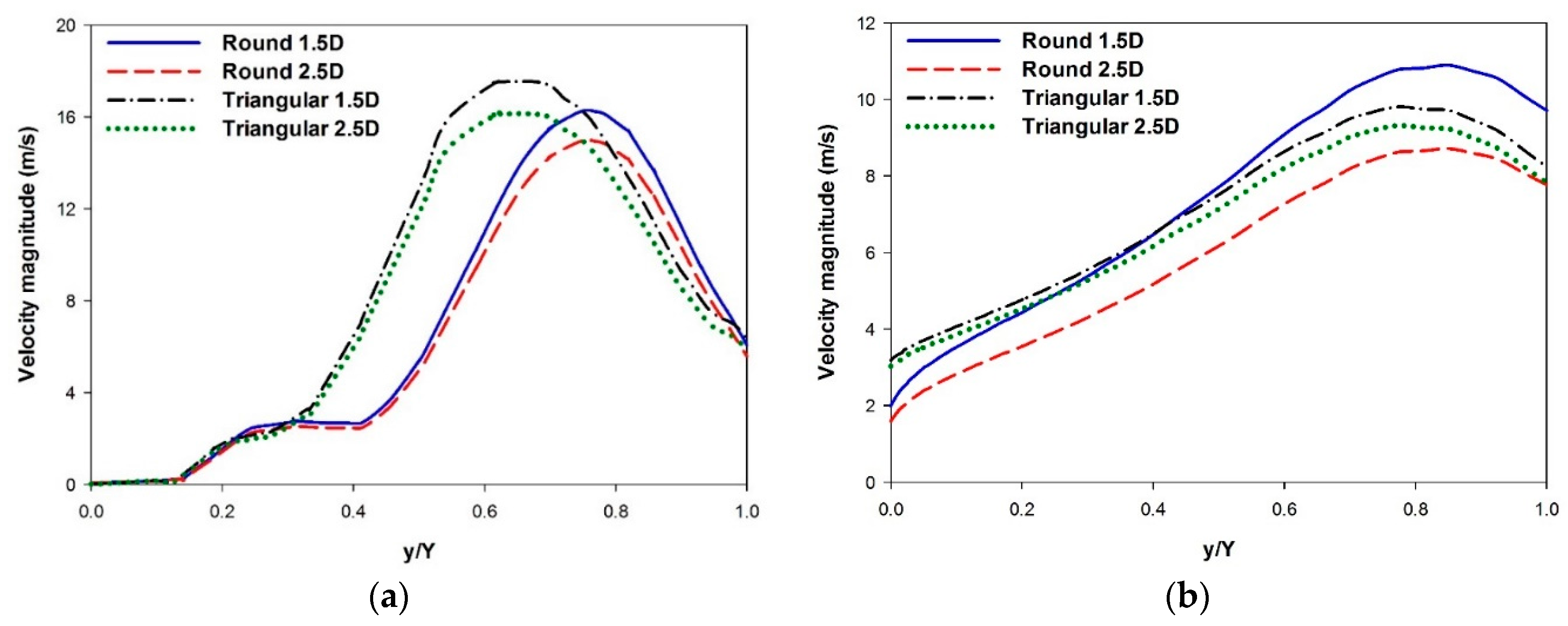
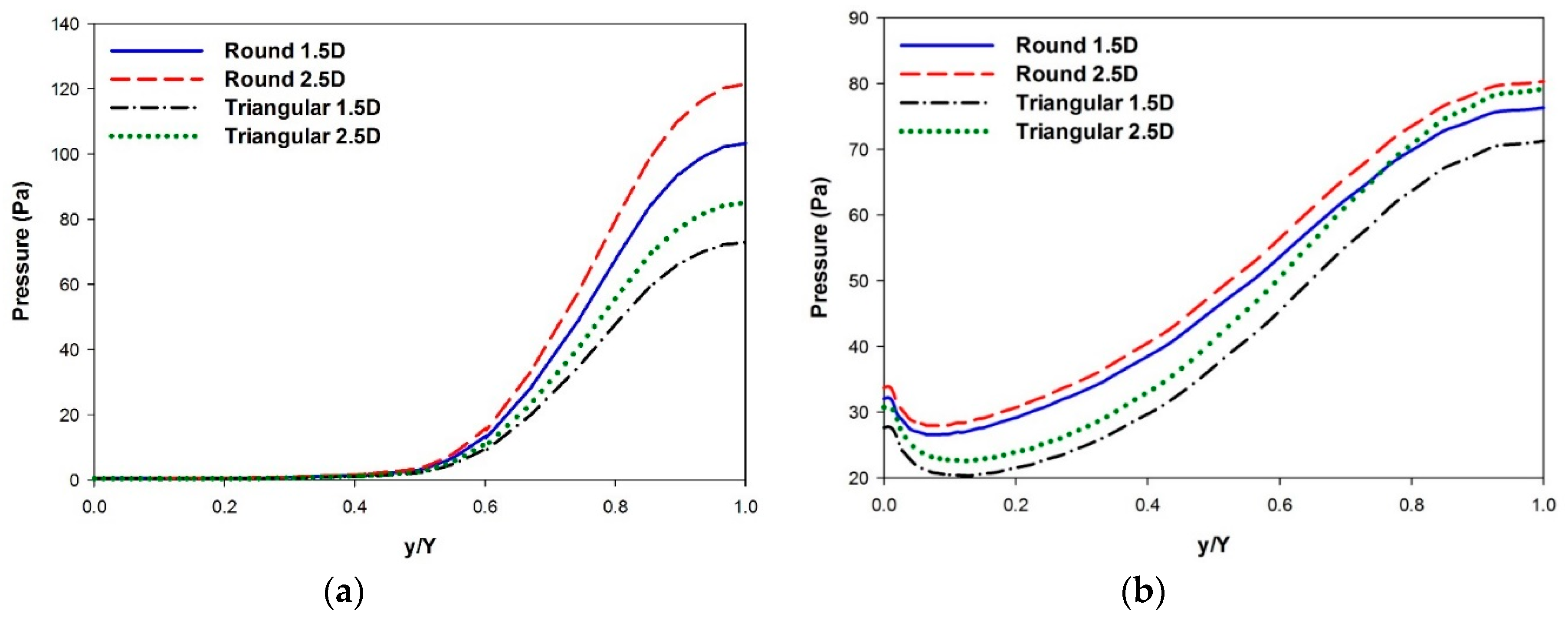
Different air duct hole shapes were introduced in the +4D separator model, as separation is superior in this model. The effect of duct hole shapes on velocity magnitude at points 1 and 2 is presented in Figure 5. The triangular-shaped duct hole resulted in higher velocity magnitude because of its sharp corner [23]. The start of the graph shows that the recirculation zone on the vibrating bed increased, which in turn increased the collection of waste materials (Figure 5a). The increase in diameter of the triangular- or round-shaped duct hole reduces the velocity magnitude, resulting in low separation of PET and PVC materials. However, the round-shaped duct hole with a diameter of 1.5D showed higher value of velocity magnitude at point 2 because of the smooth shape (Figure 5b). Thus, the kinetic energy of the ballistic trajectory is not significantly reduced [23]. The triangular-shaped duct hole with a diameter of 1.5D increased separation by increasing the velocity magnitude of the ballistic trajectory. The effect of duct hole shape was also investigated by estimating the pressure distributions in the density separator models (Figure 6). The minimum pressure value is situated near the vibrating bed, whereas the maximum is near the duct hole (Figure 6a). The round-shaped duct hole showed the highest pressure distribution values. The duct hole with a diameter of 2.5D resulted in the highest pressure and lowest velocity magnitudes at point 1. These results suggest that the triangular duct hole with a diameter of 1.5D results in an enhanced separation process, as the shape decreases the pressure distribution. Similarly, the pressure magnitude is high for the round duct hole shape as compared with the triangular shape in point 2 (Figure 6b). The increase in the size of the triangular or round duct hole also increased the pressure magnitudes. This finding implies that duct hole shapes with higher diameters are not suitable for the density separator, because the large duct holes reduce the velocity magnitude of the ballistic trajectory and increase the pressure in the separator model.
3.4. Bed Slanting Angles
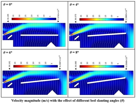
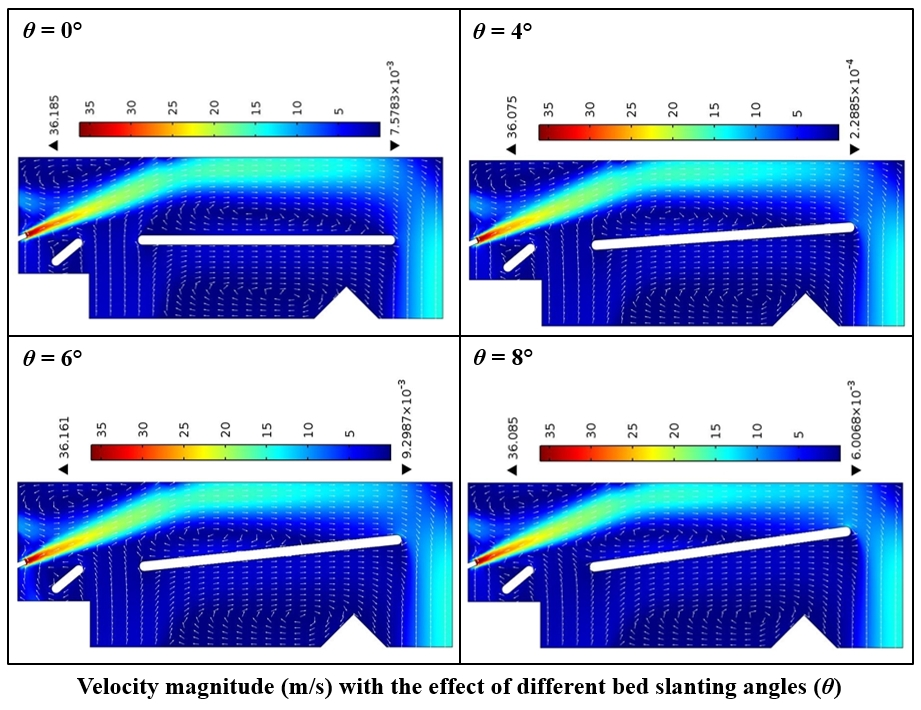
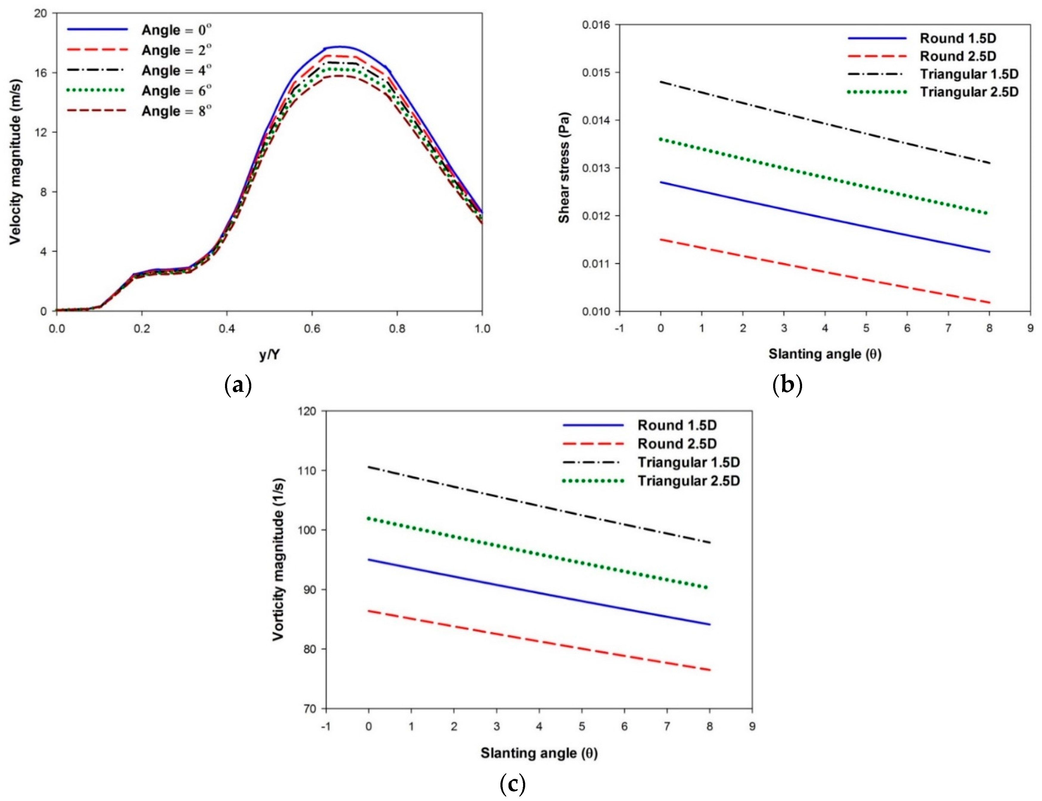
The velocity field in the +4D separator model was plotted to investigate the effect of bed slanting angles on the separation of PET and PVC plastics (Figure 7). The figure shows that the recirculation zones on the vibrating bed decrease with an increase in slanting angle. The reduction in the recirculation zone causes the majority of the plastic material to accumulate near the leading edge of the vibrating bed, which consequently affects the efficiency of the separation process [26]. The increase in slanting angles also decreases the maximum velocity magnitude of the separator model. These velocity contours suggest that the vibrating bed must not be inclined at larger angles, because the plastic materials may not undergo appropriate separation process, thereby affecting the recycling process [25,26]. The effect of bed slanting on the separation process was also investigated by computing the velocity magnitude at point 1 in the +4D separator model (Figure 8a). The graph shows that the velocity magnitude increases with the increase in bed slanting angles. The separator model with the vibrating bed inclined at higher angles results in better ballistic trajectory because of higher kinetic energy. However, higher bed slanting angles reduce the recirculation zones. Therefore, an optimized value of bed slanting angle must be selected to maintain the separation process by achieving effective ballistic trajectory [26,27].
Shear stress, a linear function of fluid velocity, is helpful in determining friction that is produced against the air ballistic trajectory. Therefore, shear stress should be estimated to completely analyze the effect of bed slanting angles with different duct hole shapes on the +4D separator model [23,30]. The maximum shear stress value is obtained when the vibrating bed is at the minimum point (θ = 0°). Increasing the bed slanting angles reduces the mean velocity magnitude of the separator model, which consequently reduces shear stress (Figure 8b). The separation of PET and PVC materials is low at larger bed inclination angles, because more friction will be applied to the airflow. The high friction will thus decrease the kinetic energy of the ballistic trajectory. The triangular duct hole with 1.5D resulted in the highest value of shear stress, which suggests that this duct shape offers greater friction to the airflow during separation process. Higher fluid friction reduces the movement of plastic materials from inlet to the vibrating bed. The intensity of turbulence in the separator model was further investigated by computing the vorticity magnitude with the effect of bed slanting angles and different duct hole shapes on the +4D separator model (Figure 8c). The vorticity magnitude shows similar patterns as shear stress because of the correlation of these two parameters [31]. Increasing bed slanting angles also decreased the vorticity magnitude in the separator model. The triangular duct hole with 1.5D resulted in the highest value of the vorticity magnitude. Higher bed slanting angles increase the kinetic energy by offering lower fluid friction. However, the recirculation zone on the vibrating bed is reduced at higher bed slanting angles. Therefore, a suitable bed slanting angle must be selected to enhance the separation process without decreasing the recirculation zone on vibrating bed.
3.5. Air Inlet Velocities
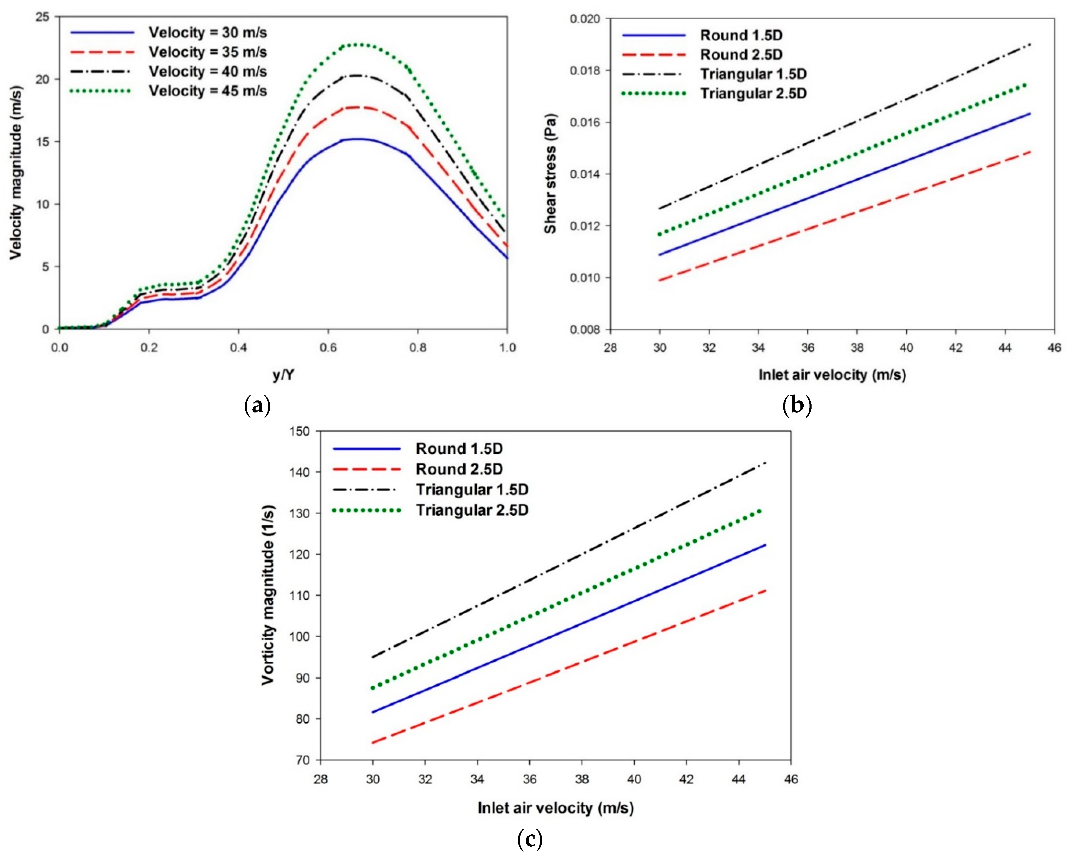
The effect of various air inlet velocities on ballistic trajectory was observed by computing the velocity magnitude at point 1 in the +4D separator model (Figure 9a). An increase in air inlet velocity also increases the kinetic energy of the ballistic trajectory, which then improves plastic separation, and vice versa. However, increasing the inlet velocity also increases shear stress, thus applying more friction to the ballistic trajectory. Shear stress is directly related to inlet fluid velocity and increases with flow velocity [30]. Shear stress increases with an increase in air inlet velocity for all duct shape models (Figure 9b). The triangular duct hole with 1.5D showed the highest value of shear stress at different inlet velocities. Similarly, the vorticity magnitude increased with an increase in air inlet velocity (Figure 9c). Again, the triangular duct hole with 1.5D showed the highest shear stress value at different inlet velocities. These results suggest that increasing the air inlet velocity improves the kinetic energy of the ballistic trajectory but increases fluid friction and turbulence in the separator model. In addition, the triangular duct hole with 1.5D showed better results with the increase in the air inlet velocity as compared with other duct shapes. Therefore, a suitable air inlet velocity must be selected to increase the separation of PET and PVC materials without increasing the fluid friction in the separator model [30].
4. Conclusions
The present study numerically investigates the flow characteristics in the air-based density separator to optimize the separation process. The study proposes a new density separator design by installing air duct holes with different diameters and shapes to improve the ballistic trajectory of the airflow. The present study considers a 2D model of the density separator to optimize the air ballistic trajectory and the inclination angles of the vibrating bed by computing the flow properties in the separator model. Various inlet air velocities, duct hole diameters and shapes, and slanting angles of the vibrating bed are employed to determine the effects of the parameters on velocity magnitude, pressure distribution, shear stress, and vorticity magnitude.
The air duct hole installed at the upper wall of the density separator improves the ballistic trajectory of the air stream. The recirculation zone formed on the vibrating bed is necessary for the collection of separated plastic material. Increasing the air duct hole diameter in a positive direction from the reference position increases the kinetic energy of the airflow. An increase in the fluid pressure negatively affects the plastic separation process. The +4D separator model increased the separation of PET and PVC material due to higher velocity and less pressure magnitudes. The introduction of triangular or round-shaped duct holes increased the kinetic energy of the ballistic trajectory. The increase in the slanting angles of the vibrating bed improves the ballistic trajectory but reduces the efficiency of the separation process by decreasing the recirculation zone on the vibrating bed. Shear stress and vorticity also increase with an increase in the bed inclination angles. The increasing air inlet velocity also increases the kinetic energy of the ballistic trajectory. An optimized value of the bed slanting angle and air inlet velocity must be selected to increase the plastic separation process. The separation process increases with the air duct hole diameter of +4D, the triangular duct hole shape (diameter of 1.5D), the low bed slanting angles (less than 4°), and the inlet air velocity of 35 m/s. Consideration of the plastic is recommended in future studies to address the real physical phenomenon in the density separator. Therefore, a numerical study is proposed to examine the effects of the interaction between air flow and plastic waste to increase the separation process.
Acknowledgments
This work was supported by a National Research Foundation of Korea (NRF) grant funded by the Korea government (MSIP) (No. 2017R1A2B2005515) and a grant from the Priority Research Centers Program through the NRF, as funded by MEST (No. 2010-0020089).
Author Contributions
Haider Ali conceived and designed the simulations and paper structure; Haider Ali performed the simulations; Kyung Won Kim designed the model and analyzed the results; Sung Gi Bang, Hyun Bae Chae and Seung Wook Shin provided the data; Cheol Woo Park gave suggestions and made corrections in the paper; Haider Ali wrote the paper.
Conflicts of Interest
The authors declare no conflict of interest.
References
- Wang, C.; Wang, H.; Fu, J.; Zhang, L.; Luo, C.; Liu, Y. Flotation separation of polyvinyl chloride and polyethylene terephthalate plastics combined with surface modification for recycling. Waste Manag. 2015, 45, 112–117. [Google Scholar] [CrossRef] [PubMed]
- Wang, C.; Wang, H.; Fu, J.; Liu, Y. Flotation separation of waste plastics for recycling—A review. Waste Manag. 2015, 41, 28–38. [Google Scholar] [CrossRef] [PubMed]
- Siddiqui, M.N. Conversion of hazardous plastic wastes into useful chemical products. J. Hazard. Mater. 2009, 167, 728–735. [Google Scholar] [CrossRef] [PubMed]
- Asokan, P.; Osmani, M.; Price, A.D.F. Assessing the recycling potential of glass fibre reinforced plastic waste in concrete and cement composites. J. Clean. Prod. 2009, 17, 821–829. [Google Scholar] [CrossRef]
- Duval, D.; MacLean, H.L. The role of product information in automotive plastics recycling: A financial and life cycle assessment. J. Clean. Prod. 2007, 15, 1158–1168. [Google Scholar] [CrossRef]
- Hopewell, J.; Dvorak, R.; Kosior, E. Plastics recycling: Challenges and opportunities. Philos. Trans. R. Soc. Lond. B Biol. Sci. 2009, 364, 2115–2126. [Google Scholar] [CrossRef] [PubMed]
- Zhang, D.Q.; Tan, S.K.; Gersberg, R.M. Municipal solid waste management in China: Status, problems and challenges. J. Environ. Manag. 2010, 91, 1623–1633. [Google Scholar] [CrossRef] [PubMed]
- Al-Salem, S.; Lettieri, P.; Baeyens, J. Recycling and recovery routes of plastic solid waste (PSW): A review. Waste Manag. 2009, 29, 2625–2643. [Google Scholar] [CrossRef] [PubMed]
- Andričić, B.; Kovačić, T.; Klarić, I. Properties of recycled material containing poly(vinyl chloride), polypropylene, and calcium carbonate nanofiller. Polym. Eng. Sci. 2008, 48, 572–577. [Google Scholar] [CrossRef]
- Braun, D. Recycling of PVC. Prog. Polym. Sci. 2002, 27, 2171–2195. [Google Scholar] [CrossRef]
- Hearn, G. May the force be with you. IEE Rev. 1997, 43, 147–151. [Google Scholar] [CrossRef]
- Davies, D.K. Charge generation on dielectric surfaces. J. Phys. D Appl. Phys. 1969, 2, 1533. [Google Scholar] [CrossRef]
- Park, C.-H.; Jeon, H.-S.; Park, J.-K. PVC removal from mixed plastics by triboelectrostatic separation. J. Hazard. Mater. 2007, 144, 470–476. [Google Scholar] [CrossRef] [PubMed]
- Hearn, G.L.; Ballard, J.R. The use of electrostatic techniques for the identification and sorting of waste packaging materials. Resour. Conserv. Recycl. 2005, 44, 91–98. [Google Scholar] [CrossRef]
- Alter, H. The recovery of plastics from waste with reference to froth flotation. Resour. Conserv. Recycl. 2005, 43, 119–132. [Google Scholar] [CrossRef]
- Shent, H.; Pugh, R.J.; Forssberg, E. A review of plastics waste recycling and the flotation of plastics. Resour. Conserv. Recycl. 1999, 25, 85–109. [Google Scholar] [CrossRef]
- Gent, M.R.; Menendez, M.; Toraño, J.; Diego, I. Recycling of plastic waste by density separation: Prospects for optimization. Waste Manag. Res. 2009, 27, 175–187. [Google Scholar] [CrossRef] [PubMed]
- Drelich, J.; Payne, T.; Kim, J.H.; Miller, J.D.; Kobler, R.; Christiansen, S. Selective froth flotation of PVC from PVC/PET mixtures for the plastics recycling industry. Polym. Eng. Sci. 1998, 38, 1378–1386. [Google Scholar] [CrossRef]
- Gent, M.R.; Menendez, M.; Toraño, J.; Torno, S. Optimization of the recovery of plastics for recycling by density media separation cyclones. Resour. Conserv. Recycl. 2011, 55, 472–482. [Google Scholar]
- Tsunekawa, M.; Naoi, B.; Ogawa, S.; Hori, K.; Hiroyoshi, N.; Ito, M.; Hirajima, T. Jig separation of plastics from scrapped copy machines. Int. J. Miner. Process. 2005, 76, 67–74. [Google Scholar] [CrossRef]
- Venkoba Rao, B.; Kapur, P.C.; Konnur, R. Modeling the size–density partition surface of dense-medium separators. Int. J. Miner. Process. 2003, 72, 443–453. [Google Scholar] [CrossRef]
- Ferrara, G.; Bevilacqua, P.; De Lorenzi, L.; Zanin, M. The influence of particle shape on the dynamic dense medium separation of plastics. Int. J. Miner. Process. 2000, 59, 225–235. [Google Scholar] [CrossRef]
- Çengel, Y.A.; Cimbala, J. Fluid Mechanics: Fundamentals and Applications, 7th ed.; McGraw-Hill Higher Education: Boston, MA, USA, 2006; ISBN 0071257640. [Google Scholar]
- He, Y. Density distribution in coal dry separation with air dense medium fluidized bed. Fuel Energy Abstr. 2002, 43, 236. [Google Scholar] [CrossRef]
- Luo, Z.-F.; Zhu, J.-F.; Fan, M.-M.; Zhao, Y.-M.; Tao, X.-X. Low Density Dry Coal Beneficiation Using an Air Dense Medium Fluidized Bed. J. China Univ. Min. Technol. 2007, 17, 306–309. [Google Scholar] [CrossRef]
- Mohanta, S.; Rao, C.S.; Daram, A.B.; Chakraborty, S.; Meikap, B.C. Air Dense Medium Fluidized Bed for Dry Beneficiation of Coal: Technological Challenges for Future. Part. Sci. Technol. 2013, 31, 16–27. [Google Scholar] [CrossRef]
- Firdaus, M.; O’Shea, J.-P.; Oshitani, J.; Franks, G.V. Beneficiation of Coarse Coal Ore in an Air-Fluidized Bed Dry Dense-Medium Separator. Int. J. Coal Prep. Util. 2012, 32, 276–289. [Google Scholar] [CrossRef]
- Hafez, K.A.; Elsamni, O.A.; Zakaria, K.Y. Numerical investigation of the fully developed turbulent flow over a moving wavy wall using k–ε turbulence model. Alexandria Eng. J. 2011, 50, 145–162. [Google Scholar] [CrossRef]
- Menter, F.R. Two-equation eddy-viscosity turbulence models for engineering applications. AIAA J. 1994, 32, 1598–1605. [Google Scholar] [CrossRef]
- Keirsbulck, L.; Labraga, L.; Gad-El-Hak, M. Statistical properties of wall shear stress fluctuations in turbulent channel flows. Int. J. Heat Fluid Flow 2012, 37, 1–8. [Google Scholar] [CrossRef]
- Kravchenko, A.G.; Choi, H.; Moin, P. On the relation of near-wall streamwise vortices to wall skin friction in turbulent boundary layers. Phys. Fluids A Fluid Dyn. 1993, 5, 3307–3309. [Google Scholar] [CrossRef]
Figure 1.
Computational model set-up of the air-based density separator system.

Figure 2.
Comparisons of velocity magnitudes at point 1 for different (a) turbulence models and (b) mesh sizes at an air inlet velocity of 35 m/s and bed slanting angle (θ) of 0°.
Figure 2.
Comparisons of velocity magnitudes at point 1 for different (a) turbulence models and (b) mesh sizes at an air inlet velocity of 35 m/s and bed slanting angle (θ) of 0°.

Figure 3.
Contour and vector plots of velocity magnitude inside (a) basic, (b) +2D, (c) +4D, (d) −2D, (e) −4D, (f) −6D, and (g) −8D separator models at an air inlet velocity of 35 m/s and bed slanting angle (θ) of 0°.
Figure 3.
Contour and vector plots of velocity magnitude inside (a) basic, (b) +2D, (c) +4D, (d) −2D, (e) −4D, (f) −6D, and (g) −8D separator models at an air inlet velocity of 35 m/s and bed slanting angle (θ) of 0°.

Figure 4.
Effect of various duct hole diameters on (a) velocity magnitudes at point 1, (b) velocity magnitudes at point 2 and (c) pressure distributions at point 1 at an air inlet velocity of 35 m/s and bed slanting angle (θ) of 0°.
Figure 4.
Effect of various duct hole diameters on (a) velocity magnitudes at point 1, (b) velocity magnitudes at point 2 and (c) pressure distributions at point 1 at an air inlet velocity of 35 m/s and bed slanting angle (θ) of 0°.

Figure 5.
Effect of various duct hole shapes on velocity magnitude at (a) point 1 and (b) point 2 at an air inlet velocity of 35 m/s and bed slanting angle (θ) of 0°.
Figure 5.
Effect of various duct hole shapes on velocity magnitude at (a) point 1 and (b) point 2 at an air inlet velocity of 35 m/s and bed slanting angle (θ) of 0°.

Figure 6.
Effect of various duct hole shapes on the pressure distributions at (a) point 1 and (b) point 2 at an air inlet velocity of 35 m/s and bed slanting angle (θ) of 0°.
Figure 6.
Effect of various duct hole shapes on the pressure distributions at (a) point 1 and (b) point 2 at an air inlet velocity of 35 m/s and bed slanting angle (θ) of 0°.

Figure 7.
Effect of bed slanting angles (θ): (a) θ = 0°, (b) θ = 2°, (c) θ = 4°, (d) θ = 6° and (e) θ = 8° on the contour and vector plots of velocity magnitude inside the separator model (duct hole diameter = +4D) at an air inlet velocity of 35 m/s.
Figure 7.
Effect of bed slanting angles (θ): (a) θ = 0°, (b) θ = 2°, (c) θ = 4°, (d) θ = 6° and (e) θ = 8° on the contour and vector plots of velocity magnitude inside the separator model (duct hole diameter = +4D) at an air inlet velocity of 35 m/s.
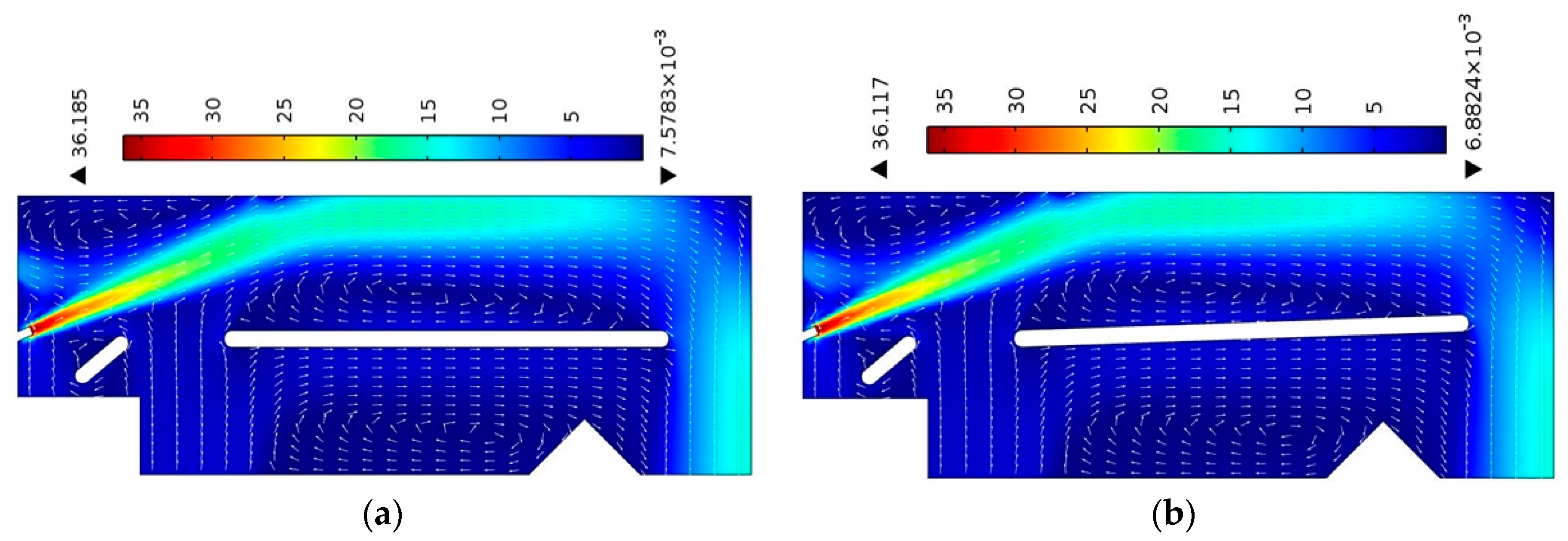
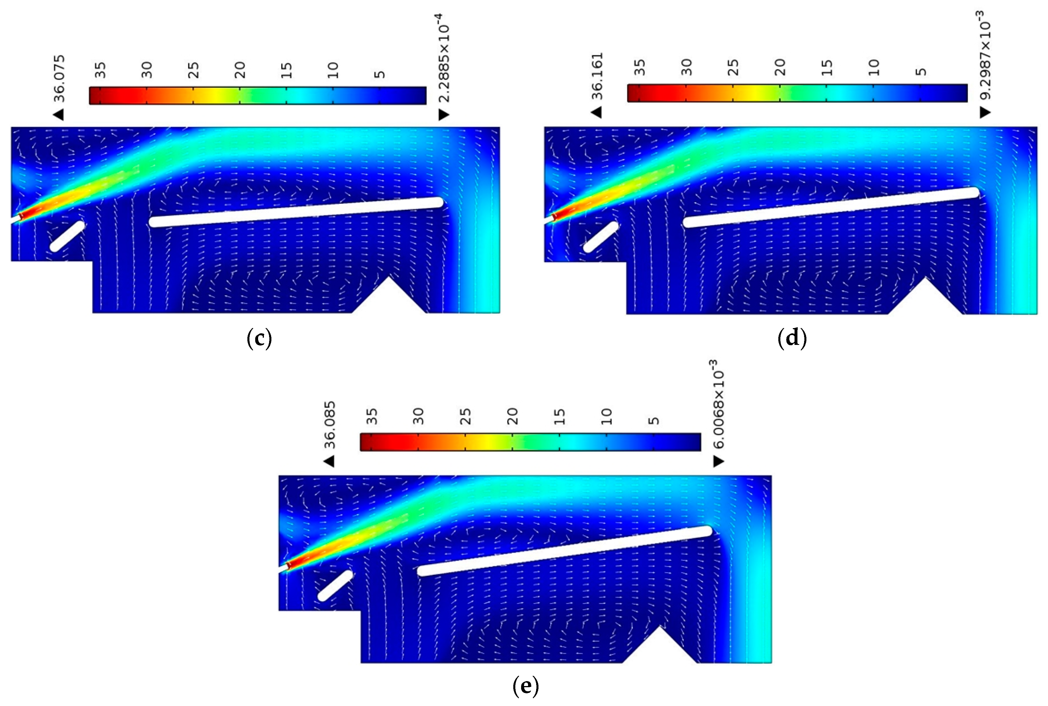
Figure 8.
Effect of bed slanting angles (θ) on the (a) velocity magnitude of +4D duct hole diameter at point 1, (b) shear stress with different duct hole shapes and (c) vorticity magnitude with different duct hole shapes at an air inlet velocity of 35 m/s.
Figure 8.
Effect of bed slanting angles (θ) on the (a) velocity magnitude of +4D duct hole diameter at point 1, (b) shear stress with different duct hole shapes and (c) vorticity magnitude with different duct hole shapes at an air inlet velocity of 35 m/s.

Figure 9.
Effect of air inlet velocity on the (a) velocity magnitude of +4D duct hole diameter at point 1, (b) shear stress with different duct hole shapes and (c) vorticity magnitude with different duct hole shapes at a bed slanting angle (θ) of 0°.
Figure 9.
Effect of air inlet velocity on the (a) velocity magnitude of +4D duct hole diameter at point 1, (b) shear stress with different duct hole shapes and (c) vorticity magnitude with different duct hole shapes at a bed slanting angle (θ) of 0°.
© 2018 by the authors. Licensee MDPI, Basel, Switzerland. This article is an open access article distributed under the terms and conditions of the Creative Commons Attribution (CC BY) license (http://creativecommons.org/licenses/by/4.0/).
Share and Cite
MDPI and ACS Style
Ali, H.; Kim, K.W.; Bang, S.G.; Chae, H.B.; Shin, S.W.; Park, C.W. Numerical Analysis to Improve the Ballistic Trajectory of an Air-Based Material Density Separator System. Appl. Sci. 2018, 8, 359. https://doi.org/10.3390/app8030359
AMA Style
Ali H, Kim KW, Bang SG, Chae HB, Shin SW, Park CW. Numerical Analysis to Improve the Ballistic Trajectory of an Air-Based Material Density Separator System. Applied Sciences. 2018; 8(3):359. https://doi.org/10.3390/app8030359
Chicago/Turabian StyleAli, Haider, Kyung Won Kim, Sung Gi Bang, Hyun Bae Chae, Seung Wook Shin, and Cheol Woo Park. 2018. "Numerical Analysis to Improve the Ballistic Trajectory of an Air-Based Material Density Separator System" Applied Sciences 8, no. 3: 359. https://doi.org/10.3390/app8030359
Note that from the first issue of 2016, this journal uses article numbers instead of page numbers. See further details here.