Effect of Stiff Hangers on the Longitudinal Structural Behavior of Tied-Arch Bridges

Civil Engineering Department, Universidad Politécnica de Cartagena (UPCT), 30203 Cartagena, Spain
*
Author to whom correspondence should be addressed.
Appl. Sci. 2018, 8(2), 258; https://doi.org/10.3390/app8020258
Submission received: 5 January 2018
/
Revised: 30 January 2018
/
Accepted: 6 February 2018
/
Published: 9 February 2018
(This article belongs to the Section Mechanical Engineering)
Abstract
:Featured Application
The conclusions of this paper could be useful for practicing structural Engineers, mainly in early stages of the design of arch bridges.
Abstract
In the design process of an arch bridge, the designer may decide to stiffen the hangers linking the arch and the deck, usually in order to reduce the internal forces or the deflections. In this paper, the effect of stiffened hangers on the longitudinal in-plane structural behavior of arch bridges is studied. Then, the effect of the stiffness of the hangers and the relevance of the arch–deck relative stiffness are shown. The paper also describes how stiff hangers with a hinge—either at the bottom or the top—combine very high structural efficiency and ease of execution. Once the advantages of stiff hangers are described and a possible drawback is highlighted. The problem may arise for stiffened hangers, as the bending moments near the ends of the deck might become more adverse for symmetrical load cases than for asymmetrical load distributions, as this usually occurs in arch bridges. To address this problem, this paper suggests a novel solution by designing a combination of fixed and pinned hangers, which can be as efficient as a configuration where all the hangers are fixed, while simultaneously reducing the bending moment at the end zones of the deck.
1. Introduction
An arch bridge is mainly composed of two elements: the deck, which provides a surface for traffic, and the arch, which is the supporting element. The arch can be over the deck or under it. Regardless, its location at the end points of the arch with respect to the deck, known as springings, tend to separate when the deck is loaded. It is very important to highlight that, to behave as an arch, the horizontal movement of the springings must be restrained, for example, by the foundations located at two hillsides. Thus, when the springing points are efficiently restrained, the arch is compressed, which is the main way the arch supports loads (See, for example, Lacidogna et al. [1]). The arch is fully compressed only when the arch thrust-line is entirely contained into the middle-third of the arch section. Otherwise, tensile stresses must be taken into account (see Accornero et al. [2] or Block et al. [3]). In the so-called ‘tied-arch’ bridge, studied in this paper, the arch is over the deck, which ties the springing points into each other. Thus, the horizontal movements of the springing are restrained by the deck. Therefore, in a tied-arch bridge the arch is compressed whereas the deck is tensioned. A general description of the behavior of an arch structure can be found in Karnowsky [4].
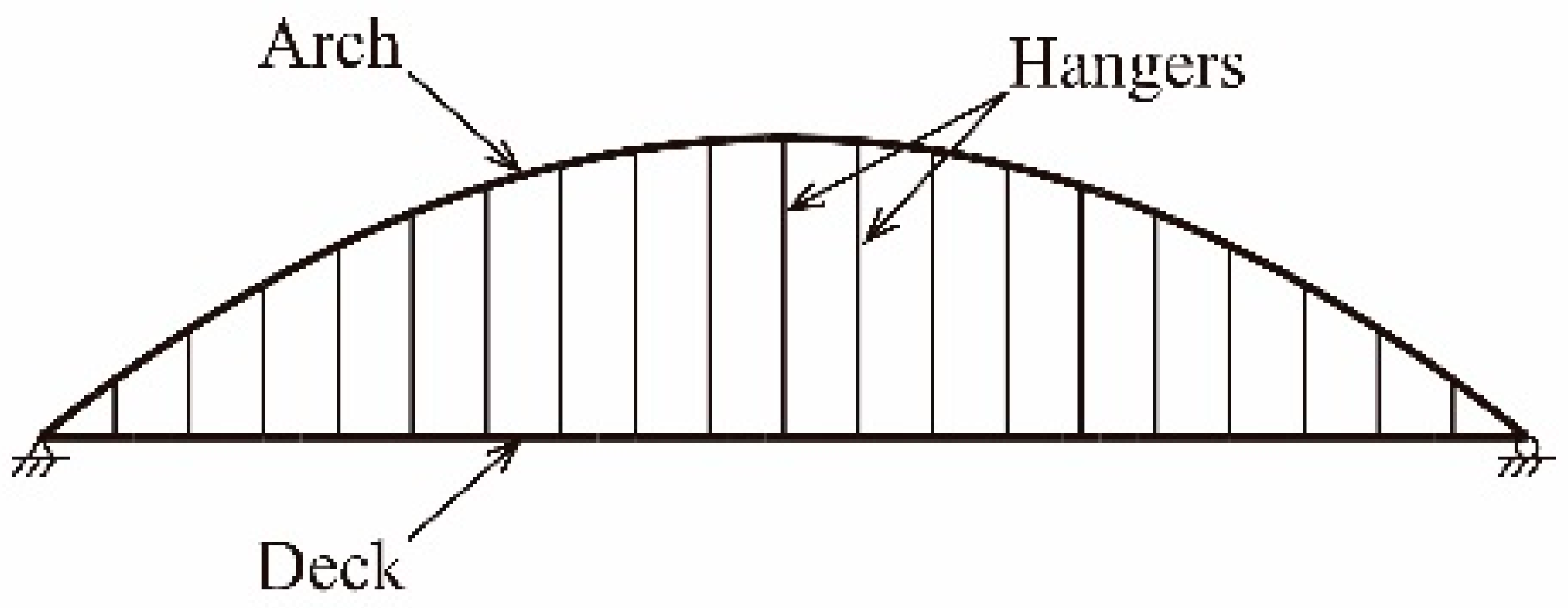
The main elements of a tied-arch bridge are shown in Figure 1. The arch and the deck are linked by a set of elements called hangers. The hangers are usually composed by steel cables, which are anchored at both ends, at the arch and at the deck (see, for example the catalogue [5] to find examples of these cables, or EC-3 [6]). An example of a tied-arch bridge, among thousands, is the bridge for the Autobahn A 42 over the Rhine–Herne Canal, shown in Figure 2.
In the early steps of the design process of an arch bridge, the most adverse load combination is usually a live load acting upon half the deck, which causes bending moments both in the arch and the deck. It will be seen that when the hangers are pinned at both ends, it can be accurately assumed that the amount of bending supported by the arch is proportional to the ratio EIA/(EIA + EID), i.e., to the ratio between the flexural stiffness of the cross-section of the arch with respect to the flexural stiffness of the arch and the deck (where E is the Young’s modulus of steel, and IA and ID are, respectively, the second moments of the area of the arch and the deck). Therefore, during the design process, it may happen that the dimensions of the cross-sections cannot prevent the failure of the bridge. Similarly, it may happen that the deflection of the deck are beyond allowable values. At this point, the designer usually decides to redesign either the cross-section of the arch, the deck, or both, according to their professional experience. However, and as an alternative, the designer may decide to stiffen the hangers linking the arch and the deck, usually in order to reduce the internal forces or the deflections; such a decision is the object of this paper.
In this paper, the effect of stiffened hangers on the longitudinal in-plane structural behavior of arch bridges is described. The study has been carried out for a reference bridge, taken as being representative of typical tied-arch bridges. Then, the effect of the stiffness of the hangers and the relevance of the arch–deck relative stiffness are shown. The paper also describes how stiff hangers with a hinge, either at the bottom or the top, combine very high structural efficiency and ease of execution. Since in-plane buckling is seldom the reason for the failure of arch bridges as described in Palkowski [8]; its effect is not considered in this study.
One of the most relevant contribution of this paper is to highlight a possible drawback of stiff hangers. The problem arises because, for stiffened hangers, the bending moments near the ends of the deck might be more adverse for symmetrical load cases than for asymmetrical loads distributions, as it usually happens in arch bridges. To address this problem, this paper suggests a novel solution by designing a combination of fixed and pinned hangers, which can be practically as efficient as a configuration where all the hangers are fixed, and simultaneously reduces the bending moment at the end zones of the deck. Thus, this solution combines structural efficiency and ease of execution.
2. Reference Bridge and Load Cases
All the bridges shown in this paper are based on a given configuration, the so-called reference bridge, shown in Figure 3. Since the study is mainly qualitative, the reference bridge is taken as being representative of typical tied-arch bridges. This reference model is composed of a straight deck supported by a vertical planar arch. The bridge belongs to the typology known as “tied-arch” bridge, since the springing points of the arch are tied by a tensioned deck. The arch and the deck are linked by a set of vertical hangers attached to the deck centerline. In the reference model, the hangers are composed of cables and are pinned at both ends. This paper focuses on the effects of stiffening these hangers.
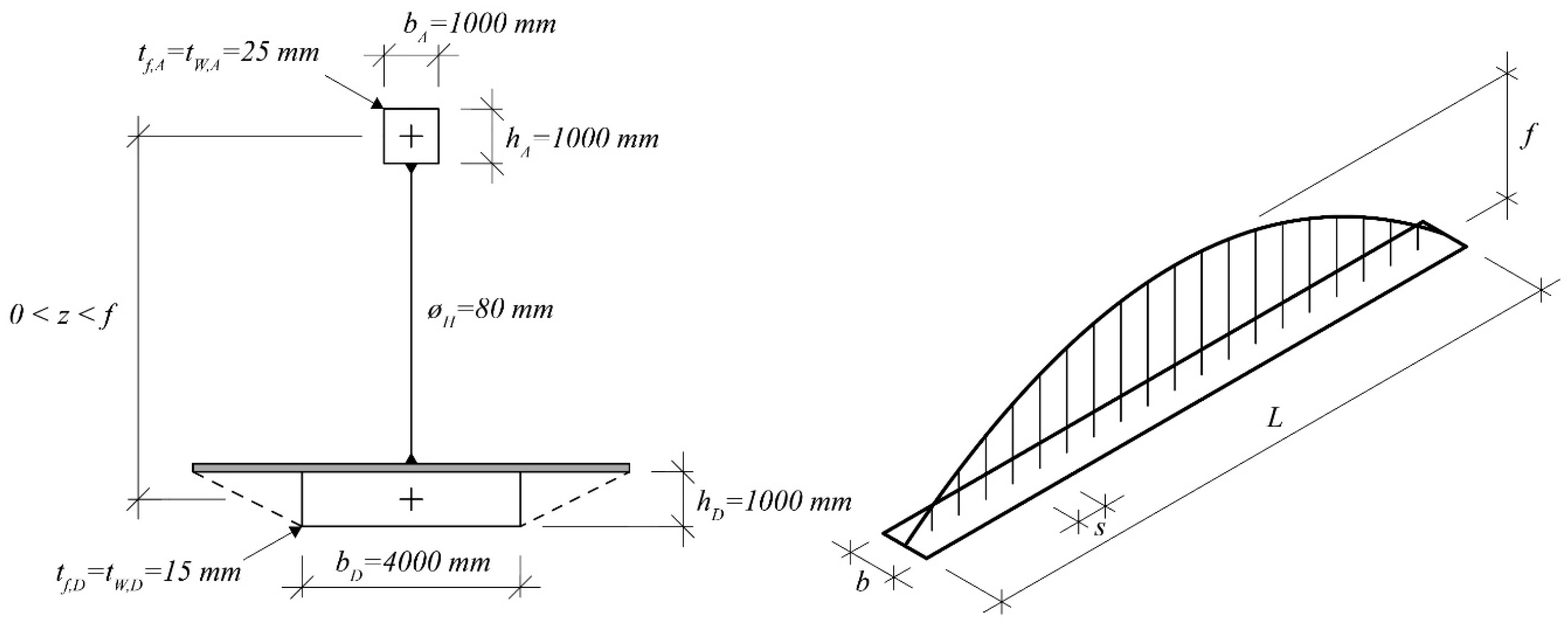
The reference model is a 100-m span (L, Figure 3) bridge. The deck spacing (s) between successive anchorages of hangers is 5.0 m. The rise of the arch (f) is 20.0 m. The loaded width of the deck, b, is 8.0 m. These dimensions have been inspired by real arch bridges, and are relatively common (see for example Leonhart [9], or Lebet [10]). All the bridges have been designed according to EC-3-2 [11].
The dimensions of the structural elements of the bridge, which are also relatively normal in bridge designs, are shown in Table 1.
Only static loads have been considered. For dynamic loads, Jong-Dar [12] and Roeder et al. [13] can be consulted. The load cases that are listed below have been considered:
- The self-weight (g), is evaluated for a specific weigh of 78.5 kN/m3, plus the dead load (gDL) on the deck (3 kN/m2). The value of the dead load corresponds to a concrete slab with 12 cm of thickness.
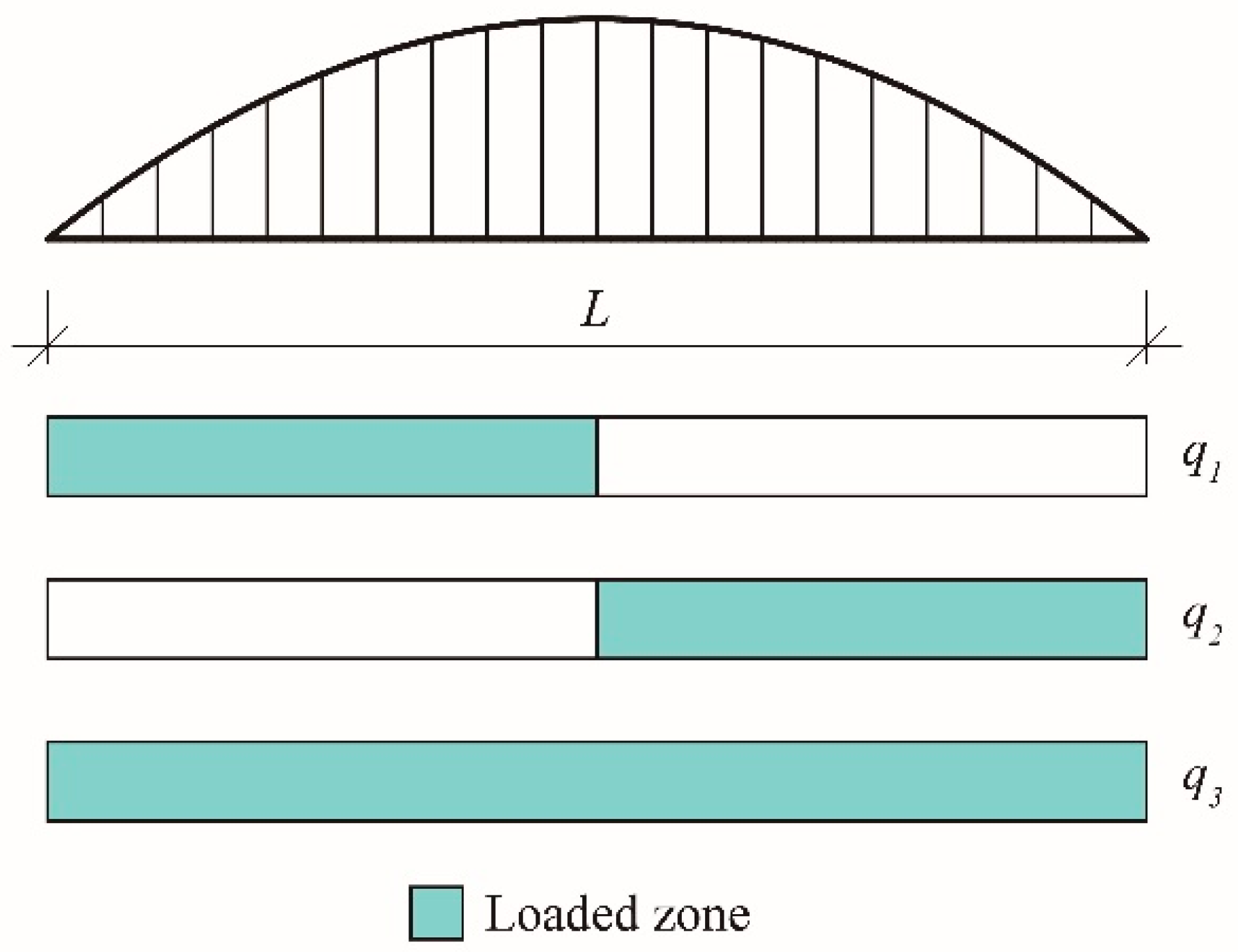
- Regarding the objective of this research, it is not necessary to consider all the possible live load cases than may appear in bridge design. Therefore, only pedestrian loads distributions will be considered, since they illustrate accurately enough the effect on the longitudinal structural behavior when the hangers are stiffened. Thus, three live loads distributions (q1, q2, q3), shown in Figure 4, have been considered, where the shadowed area is loaded with a vertical uniformly distributed load qi of 5 kN/m2 acting downwards, which corresponds to the pedestrian load defined in IAP [14] and EC-1 [15].
3. Stiff Hangers
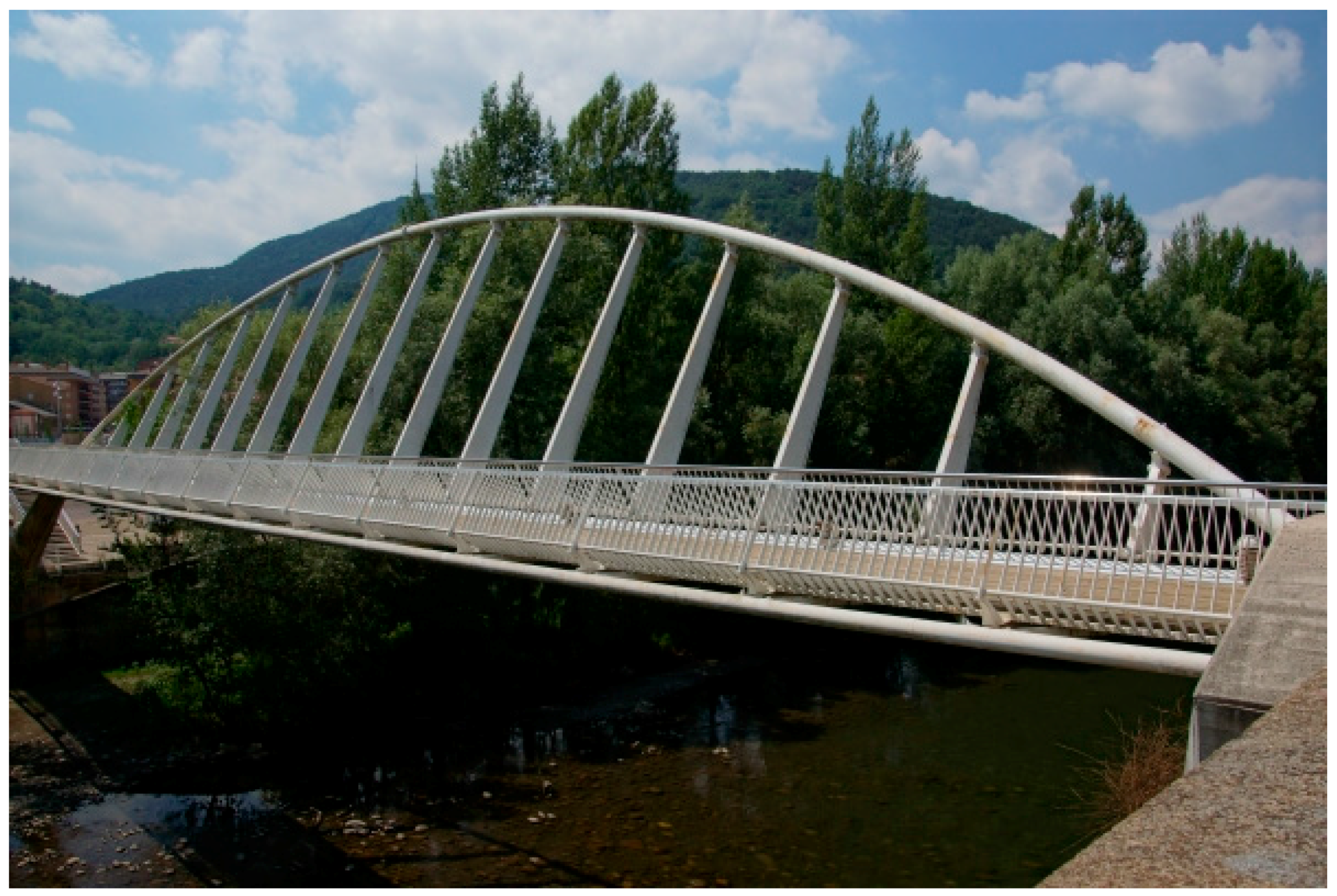
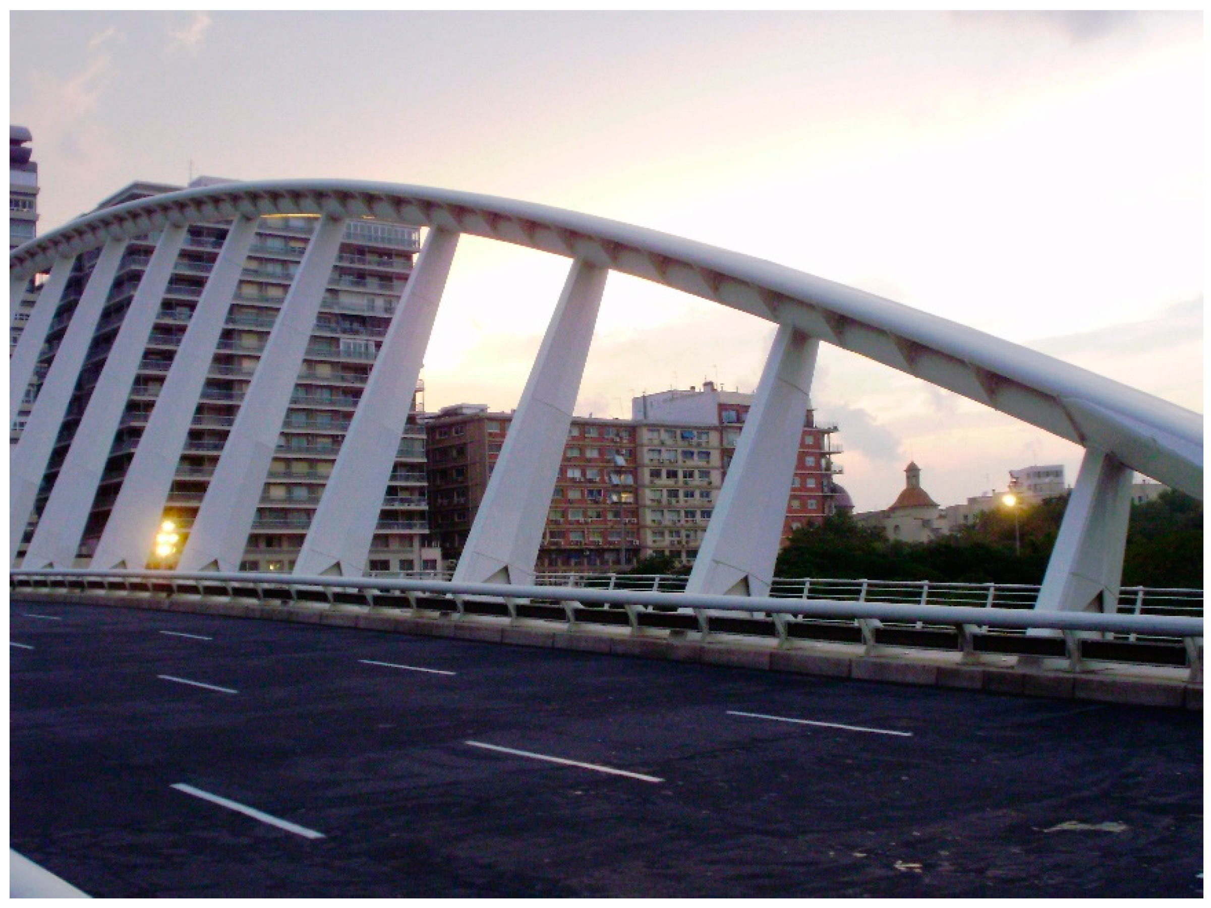
In some cases, mainly because of structural reasons, the hangers are stiffened. In these cases, the cables are substituted by H or hollow box-sections. In H-sections, the orientation of the hanger determines the bending direction where the effect of the hanger is more relevant. Two examples of Calatrava [16] illustrate this fact. In the first bridge, the Devesa footbridge (Figure 5) built in Ripoll, in northern Spain, the orientation of its H-shaped hangers is defined to provide stiffness in order to support out-of-plane bending. In the Alameda Bridge in Valencia, the hangers are fully fixed at the arch (Figure 6), which provides longitudinal in-plane stiffness.
When hangers are stiffened, the structural behavior of both the arch and the deck is modified, since they introduce concentrated bending moments at their ends. These partially counteract both the bending moments that appear in the arch and the deck of a bridge with pinned hangers. Since the bending moments are reduced, the deflection at the arch decrease accordingly. The structural behavior would be similar to that of a Vierendeel truss, i.e., a frame with no diagonal elements, employing rectangular voids. Unlike the conventional truss, it must resist significant bending forces.
In Figure 7, the Town Centre Link Bridge, in Stratford near London (UK) is shown, which is an example of a bridge where the Vierendeel truss is the main structural system. In this bridge, the upper chord is straight, as usually happens in Vierendeel trusses, whereas in an arch bridge the upper chord is curved as it is shown in Figure 5 and Figure 6.
Therefore, since stiff hangers are an efficient way to reduce internal forces and deflections both in the arch and in the deck, they can be considered as a tool for the designer, who can decide to use them within a more general design process.
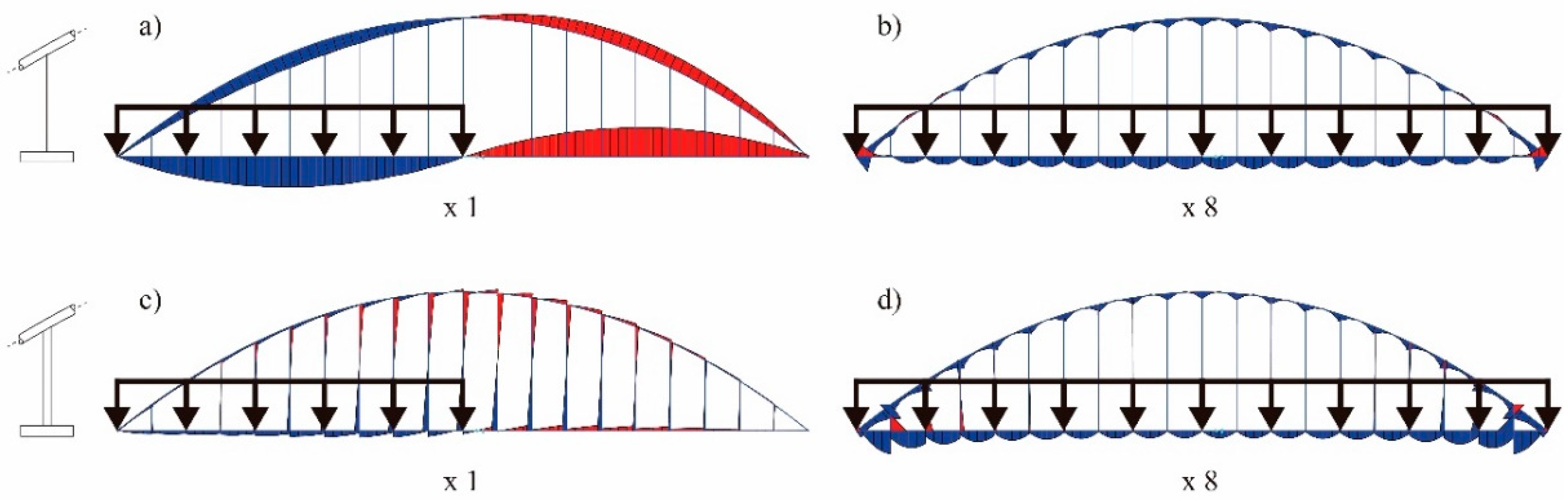
In Figure 8, the effect of stiffening the hangers in the reference bridge is shown, both for loads distributions upon half (q1) and the whole deck (q3). Regardless of the load case, it can be seen how the bending moments are always smaller for the bridge with stiff hangers. All the internal forces and deflections diagrams shown in this paper have been obtained with SAP2000 (see Computers and Structures, Inc. [20]).
3.1. Pinned vs. Stiff Hangers
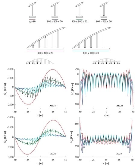
In some cases, it not strictly necessary for stiff hangers to be fully fixed at both ends. The rotation either at the bottom or the top end can be released—a decision made by the designer as a step of the design process. Figure 9 compares four configurations: for fully fixed stiff hangers, hangers pinned at the top end, the bottom end or at both ends (and composed of cables). The cross-section considered for the stiff hangers is an all-steel rectangular hollow box, 800 × 800 × 20 mm.
For the most adverse load combination (q1), it can be easily seen that when half of the deck is loaded, the bending moments both at the arch and at the deck can be reduced by stiffening the hangers. In fact, the minimum bending moments are always achieved for hangers fixed at both ends. Hangers with only one pinned end are not as efficient as fully fixed hangers. For example, when the hangers are pinned at the arch end it can be seen that the bending moment diagram is smooth for the arch, whereas it has a saw-teeth form for the deck, and vice versa. This is due to the introduction of concentrated bending moments at the fixed end (the one at the bottom) of the hangers.
However, for the live load q3 acting on the whole deck, the positive bending moments near the springings are higher for the fully fixed hangers. This effect can be explained because of the structural behavior of Vierendeel trusses. This is a possible drawback of stiff hangers, and the process of design of the structure must consider this fact.
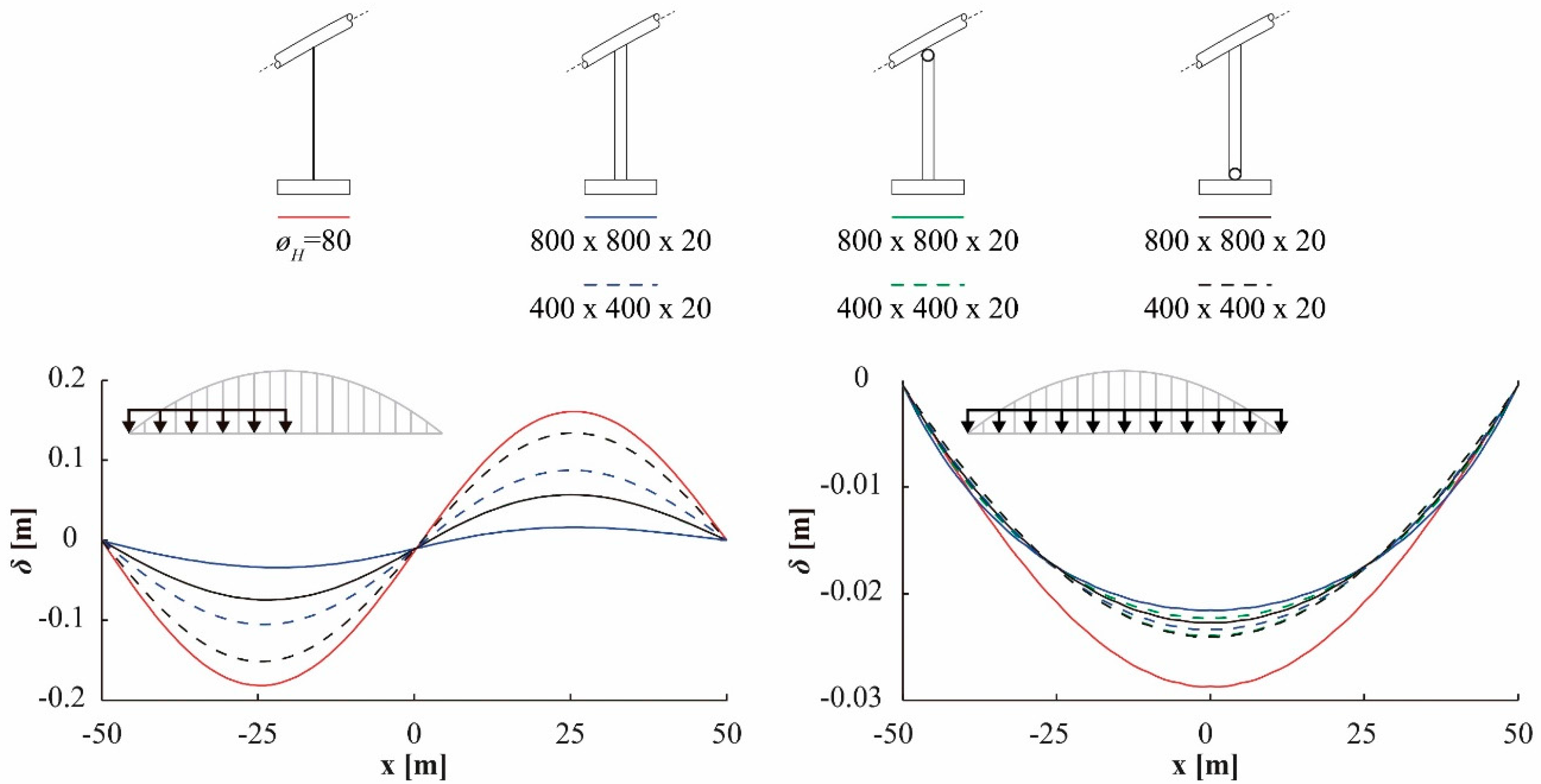
The stiff hangers are also a very efficient way to reduce the deck deflections. Figure 10 shows the effect of the hanger stiffness on the deflections of the deck under q1 and q3. The maximum reduction is always achieved for hangers fixed at both ends. Besides, for the same hanger configuration (i.e., for hinges located either at the top or at the bottom), an 800 × 800 × 20 hanger, with higher flexural stiffness, is more efficient when reducing the deflections than a 400 × 400 × 20 hanger, with lower flexural stiffness.
3.2. Effect of Hanger Stiffness.
The stiffness of the hangers is the most relevant factor governing their effectiveness in terms of reducing internal forces and deflections. In Figure 11, the bending moments both for the arch and the deck are drawn for two cross-sections of the hangers: the first one is a RHS of 800 × 800 × 20, and the second one is a RHS of 400 × 400 × 20 mm.
It can be seen how the stiffer cross-section is always more efficient. In the case shown in this example, the 400 × 400 cross-section is less efficient than the 800 × 800 section, even when it is fully fixed and has only one hinge.
However, the internal forces in the hangers increases as they become more effective. Figure 12 shows the internal forces for the two cross-sections of the hangers and for the two load cases considered. It can be seen how the 800 × 800 is the most effective cross-section, although at the expense of supporting higher bending moments for every load case.
3.3. Effect of Hanger and Deck Stiffness
In an arch bridge, the relative stiffness between the arch and the deck, (i.e., the contribution of the arch or the deck to the global flexural stiffness) is a factor of major importance when determining the structural response. In conceptual design of arch bridges, the Equations (1)–(3) (that can found, for example at Menn [21] and Manterola [22]) are considered to be accurate enough when estimating the bending moments at the arch, and at the deck, respectively MA and MD, in a bridge similar to the reference bridge:
where M represents the global bending moment and the ratio CA represents the contribution of the arch to global flexural stiffness of the arch–deck structural system.
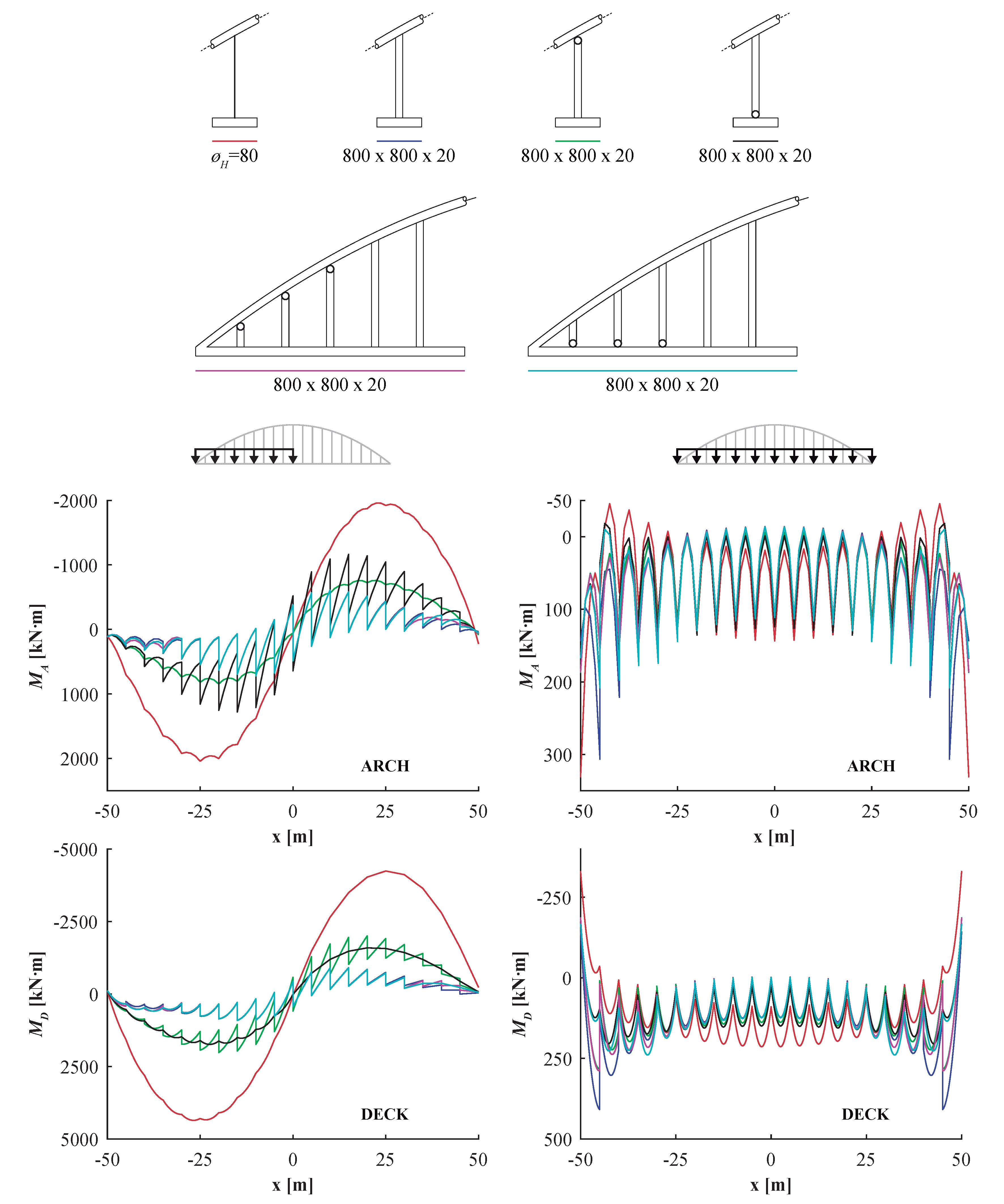
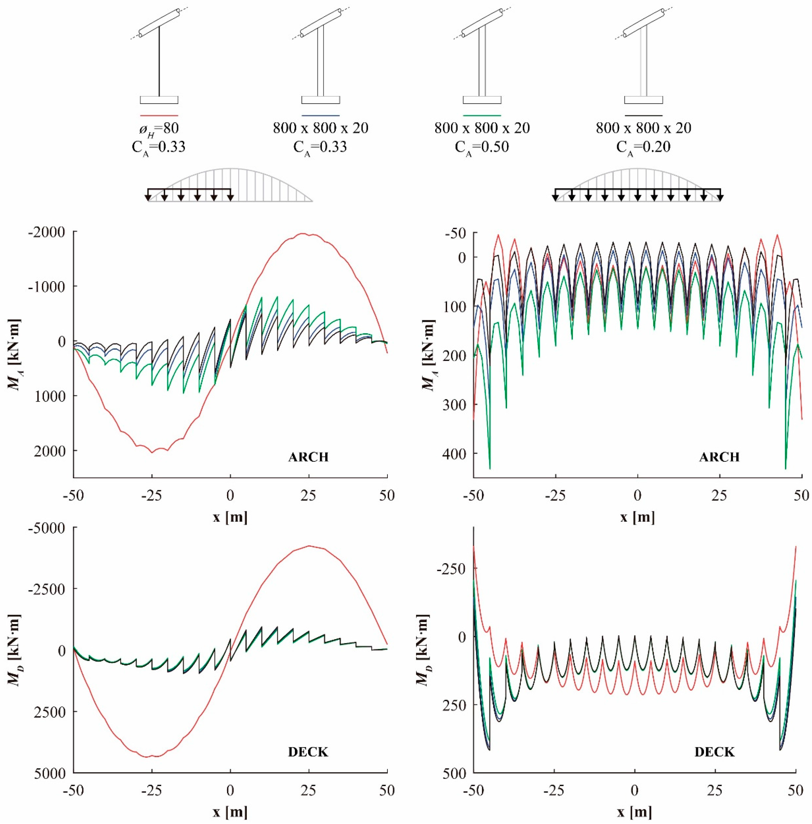
Therefore, the flexural stiffness of the hangers must be carefully studied, according to the global stiffness of the arch–deck structural system and their relative stiffness, in order to maximize its efficiency. Figure 13 shows how the bending moments distributions are modified by the effect of stiff hangers for different values of CA = 0.20, 0.33 (reference bridge) and 0.50.
4. Combination of Pinned and Stiff Hangers
In Section 3.1, it was shown that the live load acting on the whole deck, i.e., for symmetrical loads, the maximum positive bending moments near the springings appear for stiff hangers fixed in both ends. In certain cases, these bending moments could become the most adverse load combination in this zone and, therefore, determine the dimensions of this cross-section near the springings. To tackle this drawback of fixed stiff hangers, the bending moment distribution can be optimized at these zones by stiffening the central hangers only. Obviously, the exact number of hangers where the rotations are released and the location of the hinges must be specifically studied for a particular bridge. With this typological solution, the bending moment for q5 can be reduced at the deck ends (Figure 14).
In Figure 14, it can be seen how the proposed configuration, where pinned and fixed hangers are combined in the same bridge, is almost as efficient as the configuration in which all the hangers are fixed at both ends. The bending moments are very similar. In addition, the bending moments decrease at the zone near the deck ends for symmetrical loads distributions, as it was intended. Besides, the effect of releasing rotation both at the top and the bottom of the hangers is shown.
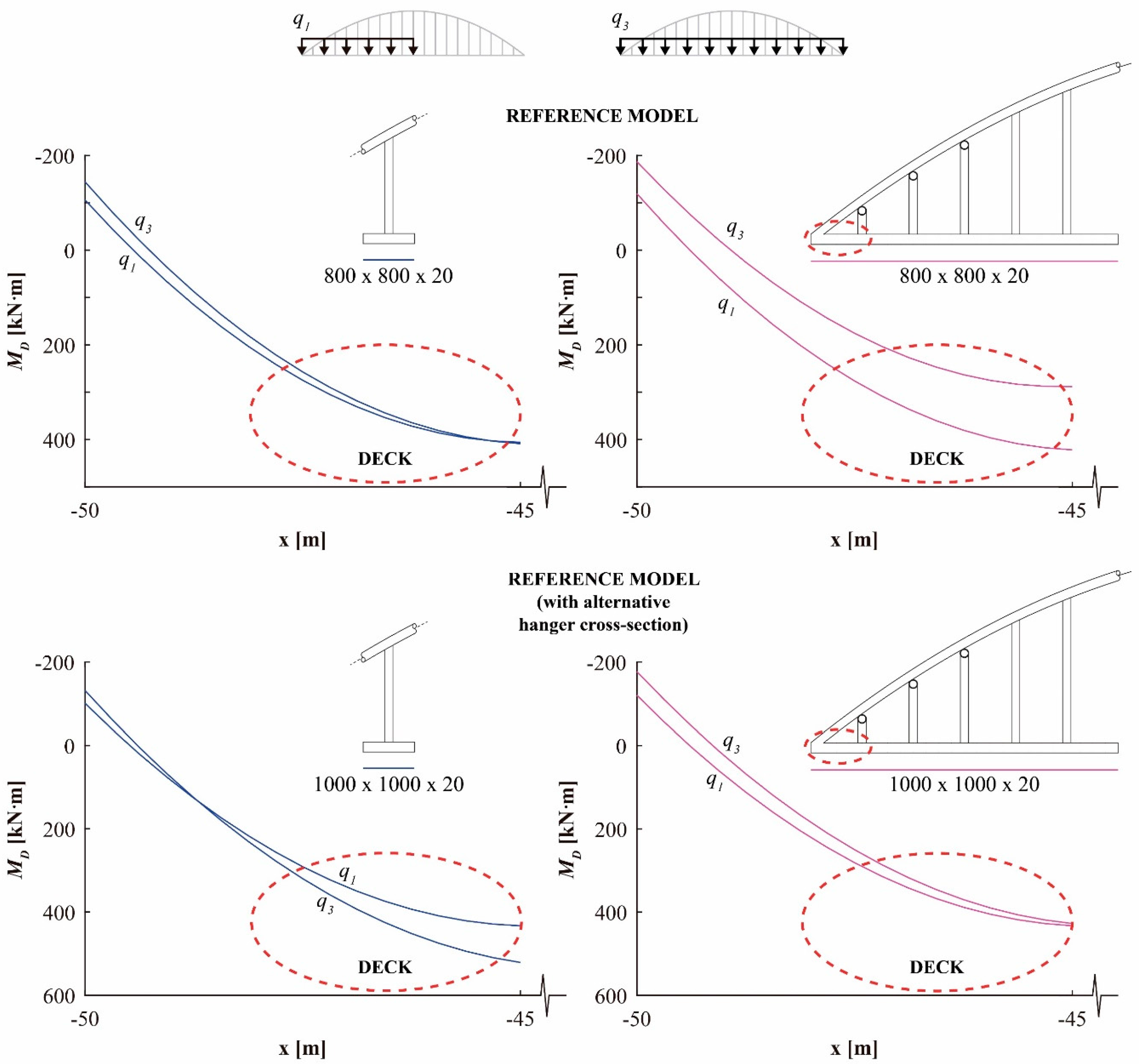
Figure 15 shows how for the reference model, the bending moments near the deck end (encircled in a dotted line) are lower under q3 than under q1 when all the hangers are fixed. This fact does not change when the three last hangers at the deck end are pinned, and q1 continues to be the most adverse load case, as it is the usual in arch bridge design. On the contrary, when an alternative 1000 × 1000 × 20 cross-section for the hangers is used, q3 becomes the most adverse load combination for that zone. In this case, a combination of pinned and fully fixed hangers can be used to correct this fact.
5. Conclusions
The main conclusions of this paper can be listed as follows:
- In this paper, the effect of stiffening hangers on the structural longitudinal in-plane behavior of arch bridges has been studied. The effect of the stiffness of the hangers, the relevance of the stiffness of arch and deck, and the consequences of hinges at the top or end or the hangers has been shown.
- Generally, stiff hangers are an efficient way to reduce the bending moments both at the arch and the deck, and to reduce deflection under live loads.
- The stiffness of the hanger is the most relevant factor governing its efficiency.
- Pinned hangers at one of their ends offer an intermediate efficiency compared to hangers fixed at both ends. In some cases, they can be an advantageous alternative, since the arch-hanger or deck-hanger connection may be simpler when no bending moment has to be transferred.
- In order to maximize its efficiency, the stiffness of the hangers must be carefully studied according to the relative stiffness of the arch and the deck, and according to the global flexural stiffness of the bridge.
- The most adverse load combination usually happens in arch bridges when half the deck is loaded. However, when the hangers are fixed and for symmetrical load cases, the values of the bending moments near the ends of the deck might be more adverse than asymmetrical load distributions. To solve this problem, this paper proposes a combination of fixed and pinned hangers, carefully studied for a given bridge, which could be almost as efficient as a configuration wherein all the hangers are fixed.
Acknowledgments
The authors wish to thank the Universidad Politécnica de Cartagena (UPCT, Spain) for the funding provided, through the research project 2007_2420, directed by the second author. In addition, the authors wish to thank the Seneca Foundation (Murcia Region, Spain), for the funding of the first author’s research scholarship (FPI).
Author Contributions
Both authors have contributed equally to this work.
Conflicts of Interest
The authors declare no conflict of interest. The founding sponsors had no role in the design of the study; in the collection, analyses, or interpretation of data; in the writing of the manuscript, and in the decision to publish the results.
References
- Lacidogna, G.; Accornero, F. Elastic, plastic, fracture analysis of masonry arches: A multi-span bridge case study. Curved Layered Struct. 2018, 5, 1–9. [Google Scholar] [CrossRef]
- Accornero, F.; Lacidogna, G.; Carpinteri, A. Evolutionary fracture analysis of masonry arches: Effects of shallowness ratio and size scale. Comptes Rendus Mécanique 2016, 344, 623–630. [Google Scholar] [CrossRef]
- Block, P.; De Jong, M.J.; Ochsendorf, J.A. As hangs the flexible line: Equilibrium of masonry arches. Nexus Netw. J. 2006, 8, 9–19. [Google Scholar] [CrossRef]
- Karnowsky, I. Theory of Arched Structures; Springer: Berlin/Heidelberg, Germany, 2012. [Google Scholar]
- Pfeifer Tension Members. Available online: https://www.pfeifer.de/emag/PFEIFER-Zugglieder/index (accessed on 2 November 2017).
- European Committee for Standardization (CEN). Eurocode 3: Design of Steel Structures—Part 1–11: Design of Structures with Tension Components; CEN: Brussels, Belgium, 2006. [Google Scholar]
- Structurae, International Database and Gallery of Structures. Available online: https://structurae.net/ (accessed on 14 November 2017).
- Palkowski, S. Buckling of parabolic arches with hangers and tie. Eng. Struct. 2012, 44, 128–132. [Google Scholar] [CrossRef]
- Leonhardt, F. Bridges [Brücken]; The Architectural Press: London, UK, 1982; pp. 38–43. ISBN 0851397646. [Google Scholar]
- Lebet, J.P.; Hirt, M.A. Steel Bridges; EPFL Press: Lausanne, Switzerland, 2013; pp. 461–488. ISBN 9781466572973. [Google Scholar]
- European Committee for Standardization (CEN). Eurocode 3: Design of Steel Structures—Part 2: Steel Bridges; CEN: Brussels, Belgium, 2006. [Google Scholar]
- Jong-Dar, Y. Vibration of parabolic tied-arch beams due to moving loads. Int. J. Struct. Stab. Dyn. 2006, 6, 193–214. [Google Scholar]
- Roeder, C.W.; MacRae, G.; Crocker, P.; Arima, K.; Wong, S. Dynamic Response and Fatigue of Steel Tied-Arch Bridge. J. Bridge Eng. 2000, 5, 14–21. [Google Scholar] [CrossRef]
- Ministerio de Fomento. Instrucción Sobre las Acciones a Considerar en el Proyecto de Puentes de Carretera, (IAP-11); Ministerio de Fomento: Madrid, Spain, 2011. (In Spanish)
- European Committee for Standardization (CEN). Eurocode 1: Actions on Structures—Part 2: Traffic Loads on Bridges; CEN: Brussels, Belgium, 2003. [Google Scholar]
- Santiago Calatrava, Architects and Engineers. Available online: https://calatrava.com/ (accessed on 6 November 2017).
- Tzonis, A. Santiago Calatrava: Obra Completa; Ediciones Polígrafa: Barcelona, Spain, 2007; ISBN 8434311518. [Google Scholar]
- Jorquera-Lucerga, J.J. Understanding Calatrava’s bridges: A conceptual approach to the ‘La Devesa-type’ footbridges. Eng. Struct. 2013, 56, 2083–2097. [Google Scholar] [CrossRef]
- Jodidio, P. Santiago Calatrava; Taschen: Cologne, Germany, 1998; pp. 36–53. ISBN 3822878839. [Google Scholar]
- Computers and Structures, Inc. Analysis Reference Manual for SAP2000® v 16; CSI: Berkeley, CA, USA, 2013. [Google Scholar]
- Menn, C. Prestressed Concrete Bridges; Birkhäuser Verlag: Vienna, Austria, 1989; pp. 382–394. ISBN 9783034899208. [Google Scholar]
- Manterola Armisén, J. Puntes (Bridge Engineering); Colegio de Ingenieros de Caminos, Canales y Puertos: Madrid, Spain, 2006; pp. 897–988. ISBN 9788438003220. (In Spanish) [Google Scholar]
Figure 1.
Structural elements of a tied-arch bridge.

Figure 2.
Bridge for the Autobahn A-42. Rhine–Herne Canal. Photo: N. Janberg (reproduced with permission from Structurae [7], 2008).
Figure 2.
Bridge for the Autobahn A-42. Rhine–Herne Canal. Photo: N. Janberg (reproduced with permission from Structurae [7], 2008).
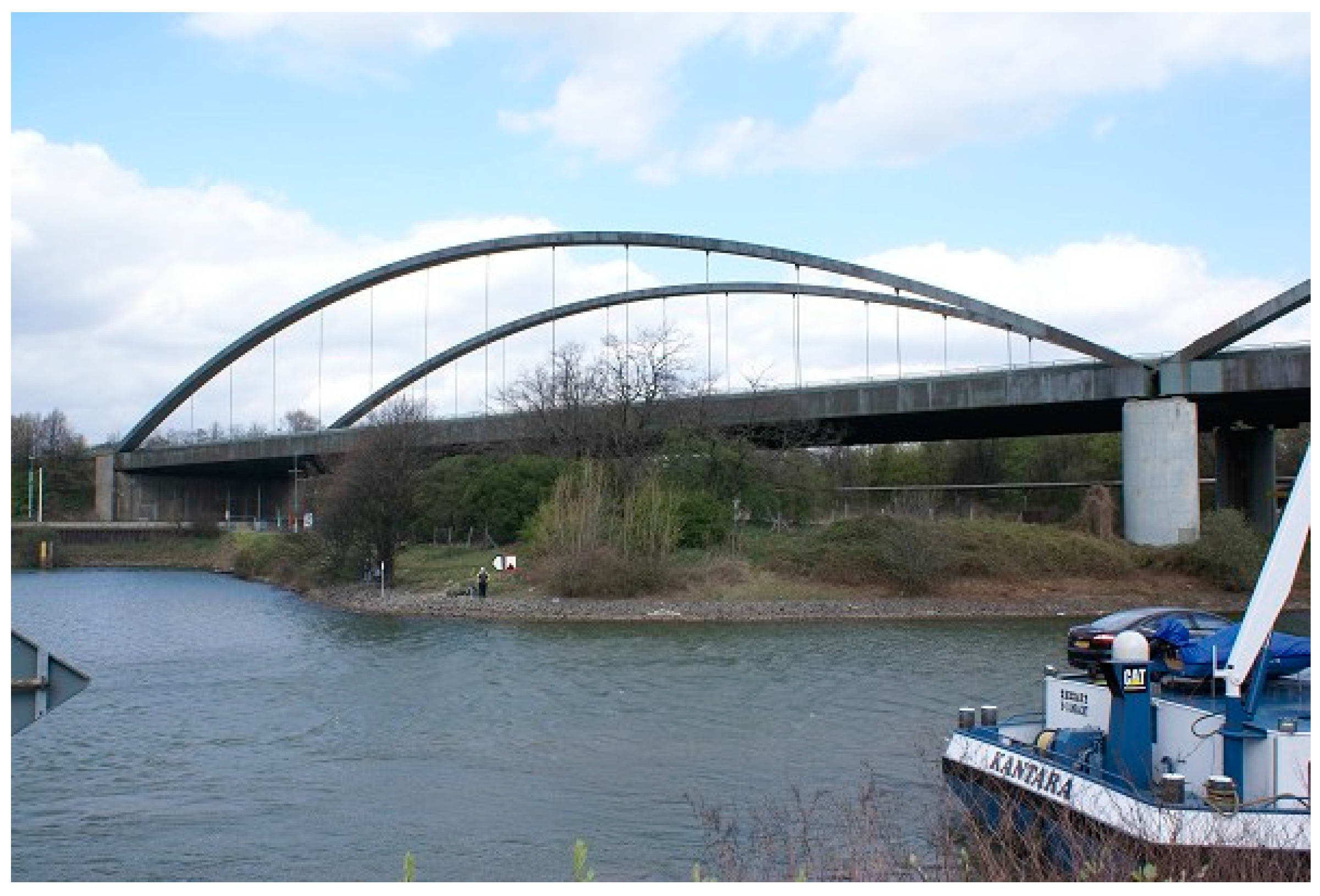
Figure 3.
Geometrical definition of the reference arch bridge (see Table 1).
Figure 3.
Geometrical definition of the reference arch bridge (see Table 1).


Figure 5.
La Devesa footbridge (See Tzonis ([17] and Jorquera-Lucerga [18]) Photo: N, Janberg (reproduced with permission from Structurae [7], 2011).

Figure 6.
La Alameda bridge. (See Tzonis [17], Jorquera-Lucerga [18] and Jodidio [19]). Photo: J.J. Jorquera-Lucerga.

Figure 7.
Town Centre Link Bridge at Stratford (UK). Photo: N. Janberg (reproduced with permission from Structurae [7], 2011).
Figure 7.
Town Centre Link Bridge at Stratford (UK). Photo: N. Janberg (reproduced with permission from Structurae [7], 2011).
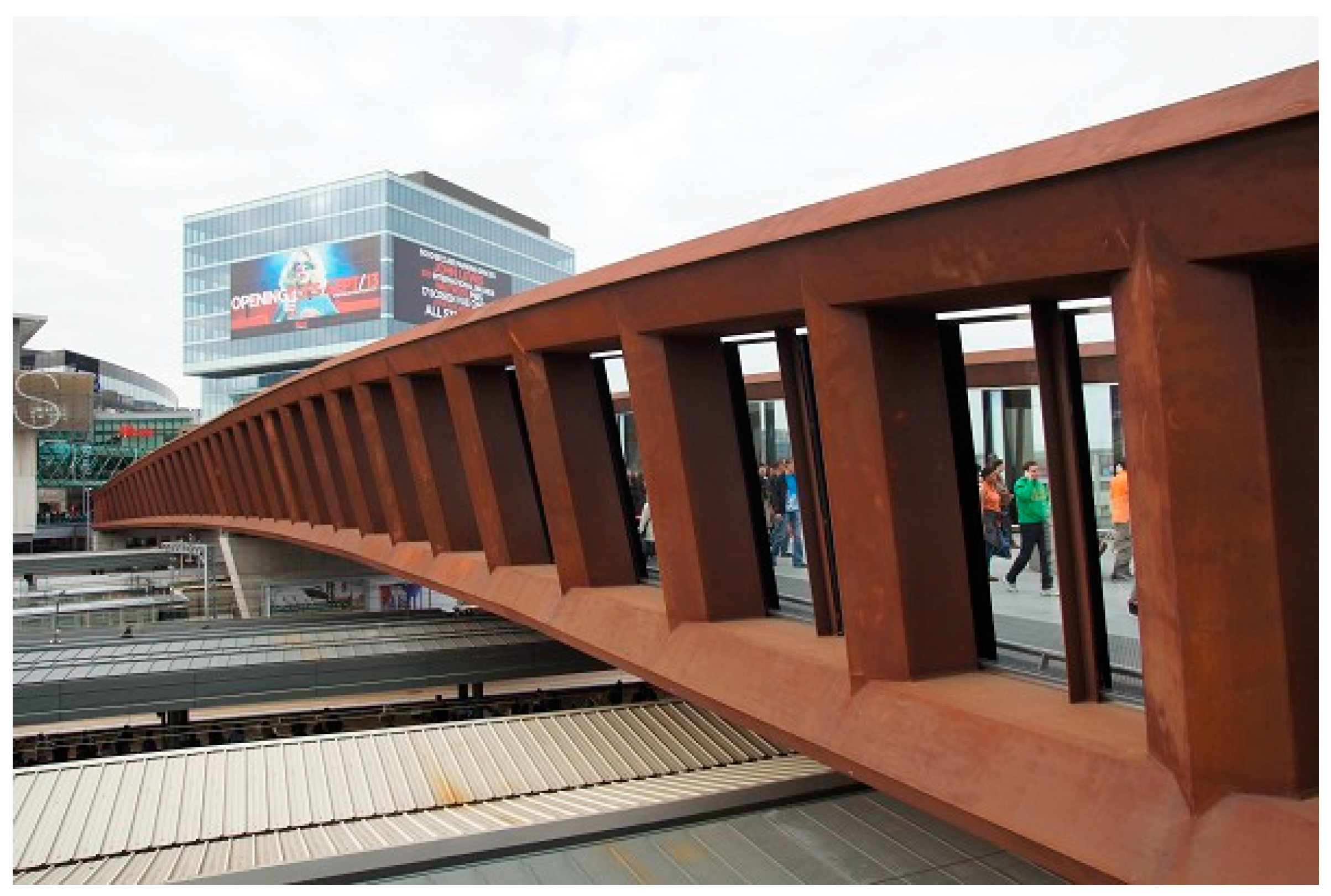
Figure 8.
Bending moment diagrams for pinned and fixed stiff hangers (800 × 800 × 20 mm). Live load distributed on half deck, q1 (a,c), and the whole deck, q3 (c,d), both for cables (a,b) and stiff hangers (c,d).
Figure 8.
Bending moment diagrams for pinned and fixed stiff hangers (800 × 800 × 20 mm). Live load distributed on half deck, q1 (a,c), and the whole deck, q3 (c,d), both for cables (a,b) and stiff hangers (c,d).

Figure 9.
Pinned and stiff hangers comparison: Bending moments at the arch and the deck.
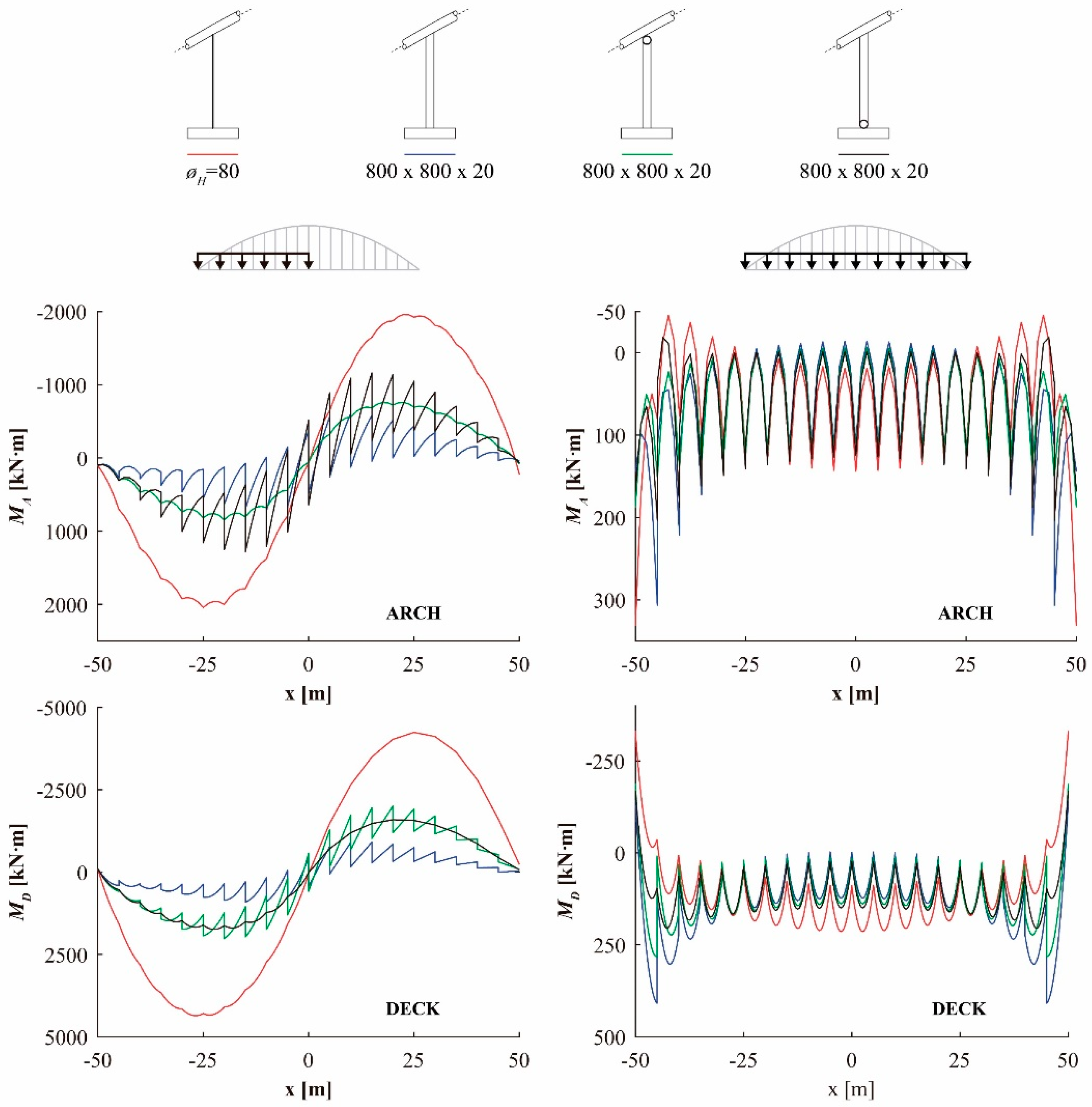
Figure 10.
Deflections for stiff hangers.

Figure 11.
Effect of the hanger stiffness: bending moment distribution at the arch and deck.
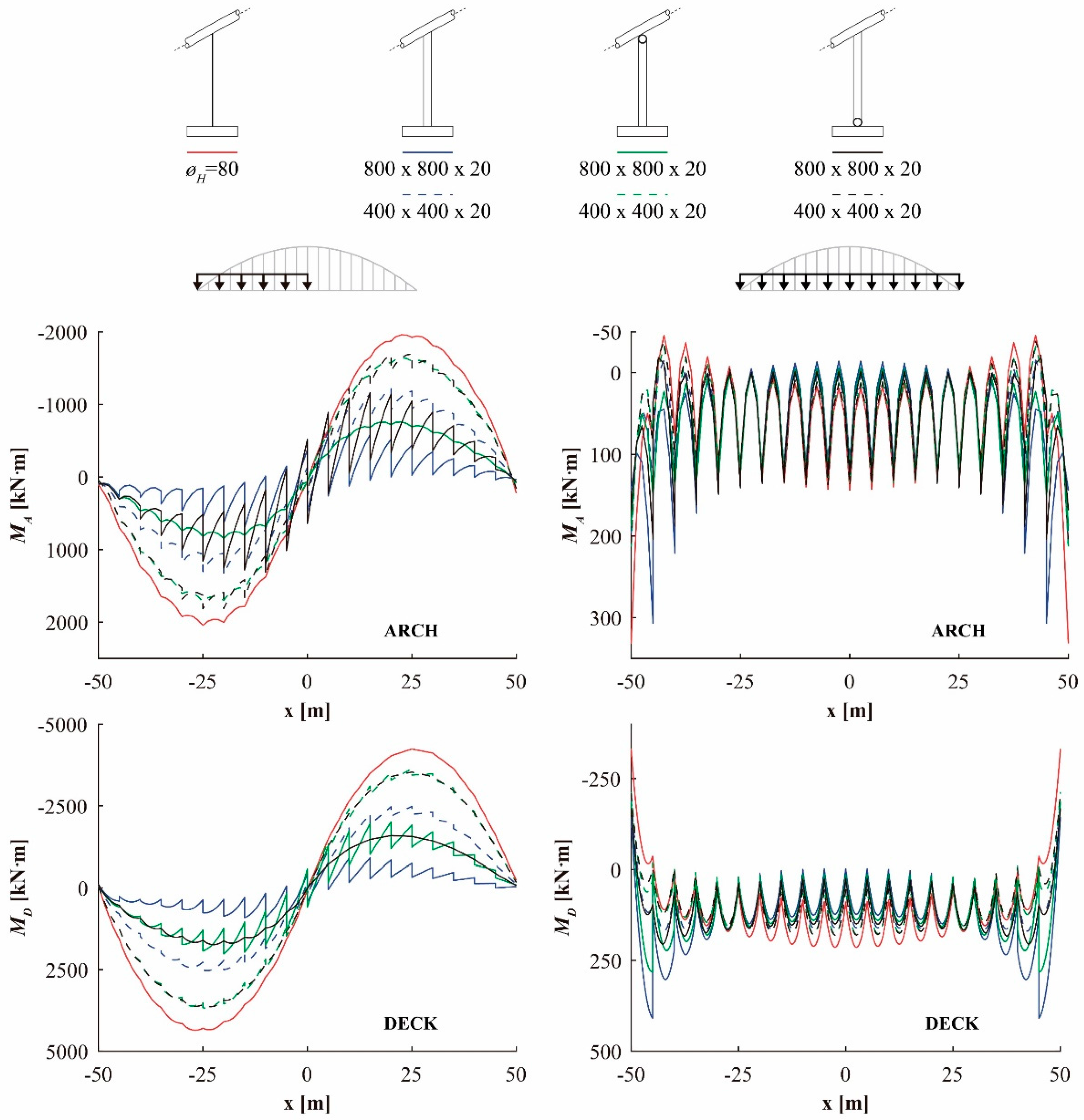
Figure 12.
Pinned and stiff hangers comparison: bending moment distribution at a hanger.
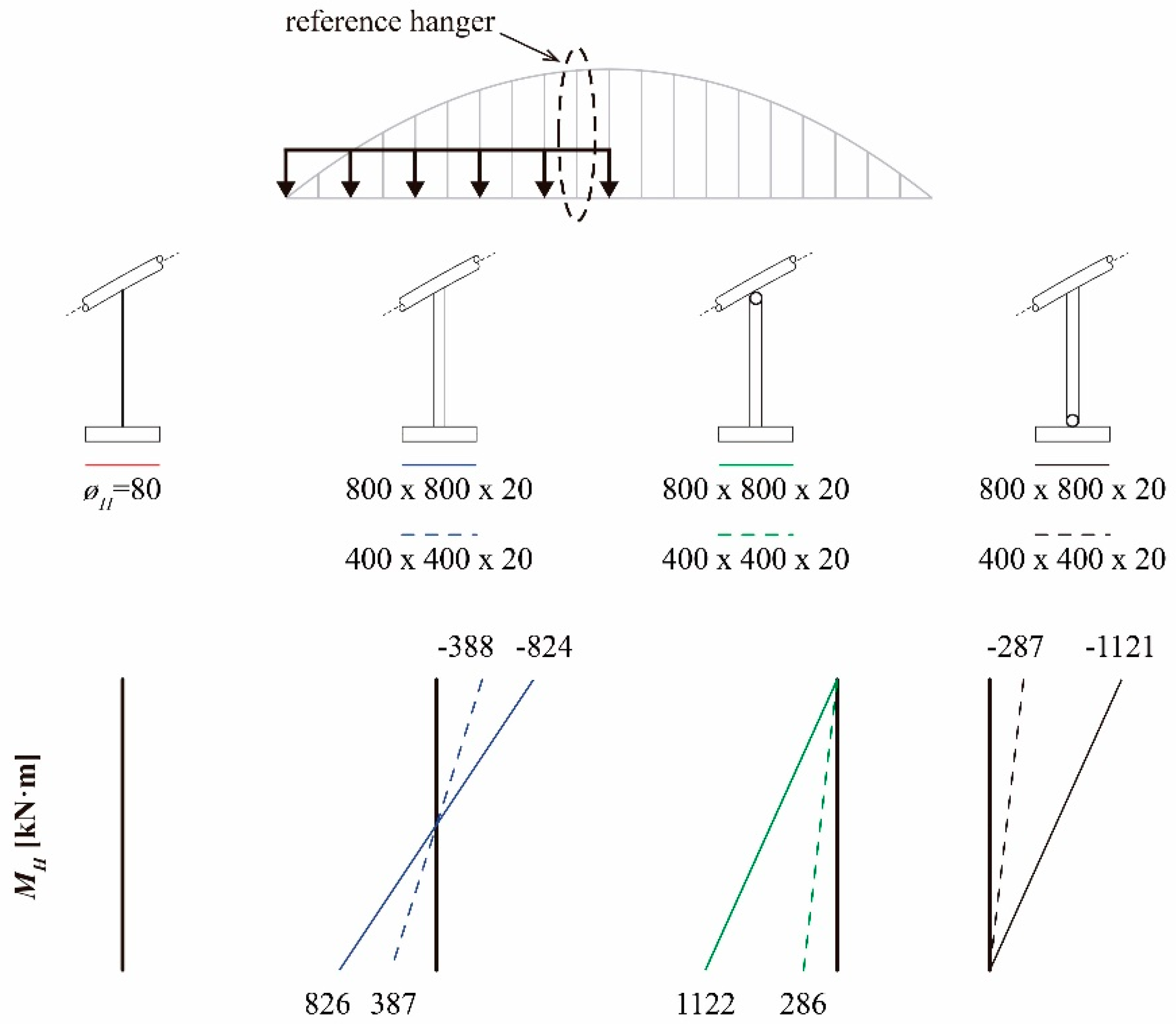
Figure 13.
Effect of a Rectangular Hollow Section (RHS) 800 × 800 × 20 mm, for CA = 0.20, 0.33 (reference bridge) and 0.50.
Figure 13.
Effect of a Rectangular Hollow Section (RHS) 800 × 800 × 20 mm, for CA = 0.20, 0.33 (reference bridge) and 0.50.

Figure 14.
Bending moments for stiff and pinned hanger distribution.
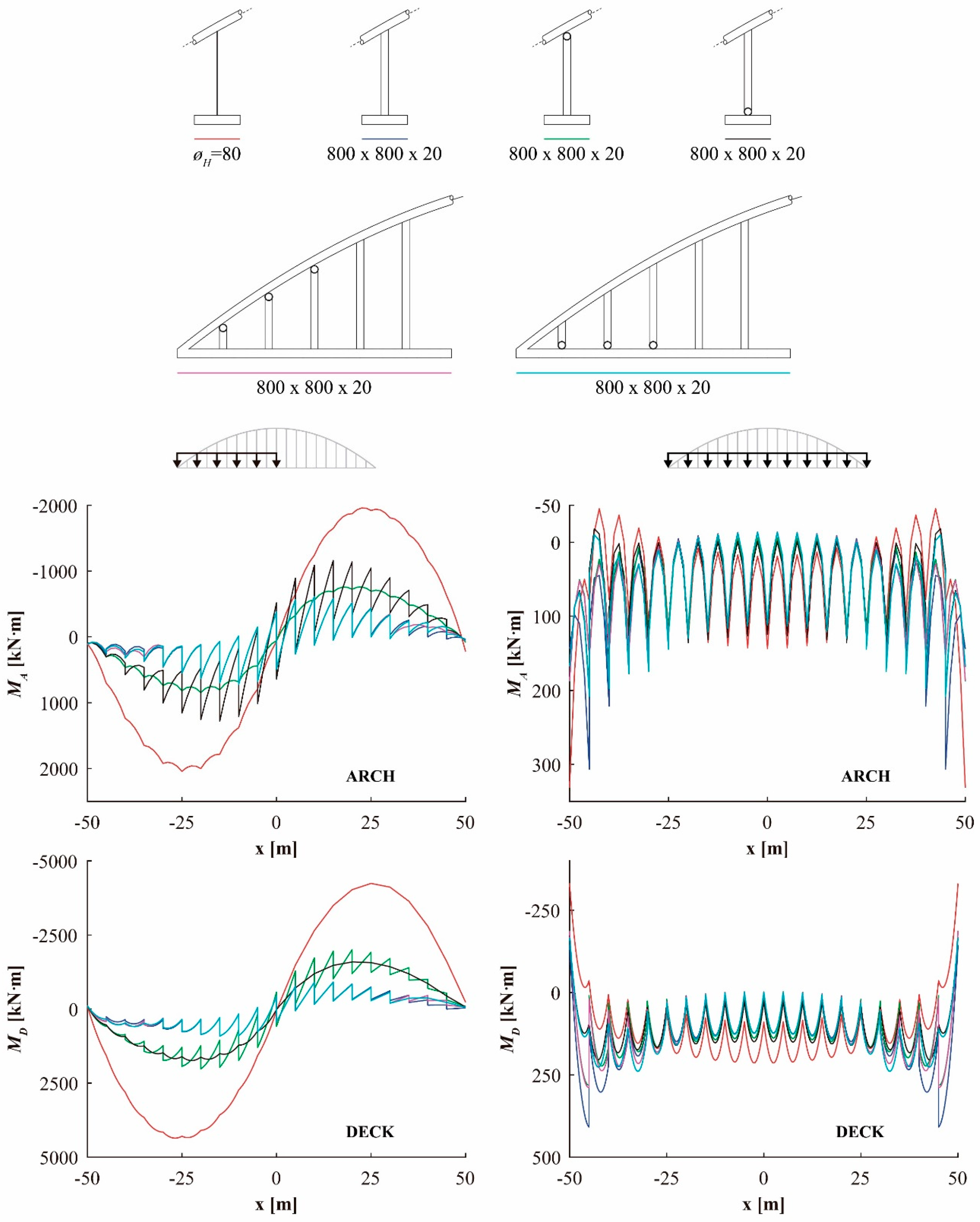
Figure 15.
Effect of mixed fixed-pinned hangers on the reduction of bending moments under q3.


Table 1.
Materials and dimensions of the structural components of the reference arch bridge.
| Element | Cross-Section | Dimensions | Young’s Modulus E (kN/m2) |
|---|---|---|---|
| Arch | Square box hollow section (SHS) | 1000 × 1000 mm, tf,A = tw,A = 25 mm | 2.0 × 10⁵ |
| Hangers | Circular solid section | ø 80 mm | 1.6 × 10⁵ |
| Deck | Rectangular hollow section (RHS) | 4000 × 1000 mm, tf,D = tw,D = 15 mm | 2.0 × 10⁵ |
© 2018 by the authors. Licensee MDPI, Basel, Switzerland. This article is an open access article distributed under the terms and conditions of the Creative Commons Attribution (CC BY) license (http://creativecommons.org/licenses/by/4.0/).
Share and Cite
MDPI and ACS Style
García-Guerrero, J.M.; Jorquera-Lucerga, J.J. Effect of Stiff Hangers on the Longitudinal Structural Behavior of Tied-Arch Bridges. Appl. Sci. 2018, 8, 258. https://doi.org/10.3390/app8020258
AMA Style
García-Guerrero JM, Jorquera-Lucerga JJ. Effect of Stiff Hangers on the Longitudinal Structural Behavior of Tied-Arch Bridges. Applied Sciences. 2018; 8(2):258. https://doi.org/10.3390/app8020258
Chicago/Turabian StyleGarcía-Guerrero, Juan Manuel, and Juan José Jorquera-Lucerga. 2018. "Effect of Stiff Hangers on the Longitudinal Structural Behavior of Tied-Arch Bridges" Applied Sciences 8, no. 2: 258. https://doi.org/10.3390/app8020258
Note that from the first issue of 2016, this journal uses article numbers instead of page numbers. See further details here.