Effect of Thin Cement-Based Renders on the Structural Response of Masonry Wall Panels


Department of Engineering, University of Perugia, Via Duranti 93, 06125 Perugia, Italy
*
Author to whom correspondence should be addressed.
Appl. Sci. 2018, 8(1), 98; https://doi.org/10.3390/app8010098
Submission received: 19 December 2017
/
Revised: 4 January 2018
/
Accepted: 9 January 2018
/
Published: 11 January 2018
(This article belongs to the Section Materials Science and Engineering)
Abstract
:URM (Unreinforced Masonry) historic buildings can be generally arranged into three categories: adobe, brick and stone masonry. However, a common feature of URM structures is typically the low mechanical properties of the masonry material, especially in terms of shear strength. URM buildings are not amenable to seismic analysis, and the relatively low strength of stone and brickwork masonry often requires expensive and invasive retrofitting intervention. Hard, intractable stones broke artificially or naturally into random shapes were often used for construction in many parts of Europe and constitute the main material of historic buildings. Thin, cement or lime-based renders are often employed to protect masonry construction, but these are frequently ignored in analysis and design. This paper shows how standard, thin, cement-based renderings can highly enhance the lateral load-capacity and shear stiffness of wall panels. An experimental campaign was carried out on-site to assess the effect of cement-based renders. In detail, compression and shear tests were conducted on twelve full-scale wall panels up to failure, and comparisons are presented to study the effect of cement-based renders on the structural behavior of stone and brickwork masonry panels.
1. Introduction
From medieval times to the modern era, the use of stone for private, public and religious buildings and infrastructures was very common in many parts of Europe. Especially in areas where it was abundant, perfectly cut, roughly squared or irregular stone became the material of choice for important houses and other domestic buildings [1,2]. Rubble or straight cut stone, sometimes with only minimal dressing and often rendered or flush-pointed, was not only used for humbler buildings, but often for standard houses and religious buildings in many rural areas [3,4,5]. Brickwork masonry is relatively more recent in Europe: solid hand-made bricks were used with increasing diffusion and frequency from the 1600s. Initially, these artificial blocks were used for public buildings or infrastructures, but they became extremely common in the 19th century in many parts of Europe in the housing construction industry [6,7].
Today, most of these buildings belong to the cultural heritage and their conservation is often a priority for local governments and conservation bodies. However, historic masonry buildings have been designed in the past with little or no regard for the effects of the seismic action. Unreinforced masonry (URM) walls are prone to failure when subjected to out-of-plane or in-plane seismic loads [8,9,10,11,12].
Several retrofitting techniques have been studied with the aim of improving the in-plane [13,14,15,16,17] or the out-of-plane behavior [18,19]. With regard to the techniques for the in-plane reinforcement, several retrofitting methods have been proposed: grout injections [20,21], joint repointing [22], ferro-cement coatings [23], application of FRP (Fiber Reinforced materials) grids or fabrics [24,25,26,27,28,29].
In this area, a standard method to “measure” the effectiveness of a new retrofitting method is to compare the load-capacity and the overall structural behavior before and after the application of the reinforcement. Control, or un-reinforced walls, are often tested on-site or in the laboratory without the pre-existing plaster or the render. However many rubble stone walls were originally lime-rendered for essential protection, with the exception of perfectly-cut stone buildings, for which the exterior walls were often left exposed (fair-faced masonry) and would have gradually weathered. This was particularly true in the case of public buildings, where an overhanging roof provided protection, and infrastructures (bridges, stations, etc.). Rubble or pebble stone walls, which were more exposed to driving rain, were more likely to be plastered with a lime slurry.
However, starting from the 1930–1940s when the use of cement became frequent, cement-based mortars have been commonly used for rendering and replaced the pre-existing lime based soft mortars. In 1824, Joseph Aspdin, a Leeds bricklayer, patented Portland cement and by the end of 19th century, a dramatic increase in production occurred. Cement-based mortars have compressive and tensile strengths that are roughly 10–30 times higher compared to the corresponding strengths for a lime-based mortar [30]. However, this depends strongly on the ratios between the main mortar components (cement, sand, water and air).
A significant difference in mechanical properties can be also noted by comparing cement-based mortars and historic masonry material. By considering masonry as an assemblage of blocks (bricks or stones) with explicitly defined geometry and lime-based mortar, its mechanical properties are dependent on the properties of its components and are strongly governed by the weakest (usually the mortar).
Today, it is very common to find historic masonry constructions rendered with strong, high-strength cement-based mortars. When a building is under the protection of a Conservation body, the re-application of lime-based renderings for rubble or pebble stone walls is often suggested or imposed. However, the removal of a cement-based render is sometimes a difficult task, which can damage the integrity of the walls. In other cases, when the building is not protected, cement-based renders are left standing, or even applied for cost reasons, ease of application, standard practice.
As a conclusion, it is very common to find historic constructions, both listed and not, rendered using cement based renders that could be 10–30 mm thick. However, pre-existing or new renders are frequently ignored in analysis and design by structural engineers in their calculations. While in no way suggesting to consider thin cement-based renderings as a viable retrofitting method, this paper will show that the lateral and compressive capacities of brick and stone work panels may be significantly altered when a cement-based render is applied.
2. Description of the On-Site Experimental Campaign
An experimental testing program was implemented to investigate the effect of thin cement-based renders on the structural behaviour of historic wall panels. Four masonry buildings have been selected for the experimental campaign. All of them were erected in the 1900–1920s, using barely-cut stones, solid engineering bricks and a lime based mortar. Figure 1 shows the four buildings.
The buildings did not suffer extensive structural damage during recent Italian earthquakes. The locations of the wall panels to be extracted from the buildings were carefully selected to avoid areas where the masonry was damaged or cracked. The cutting locations were clearly marked, and all the cuts were made using a masonry cutting chainsaw.
2.1. Masonry Typologies and Walling Materials
The buildings have a similar masonry arrangement and are located in the countryside of Central Italy. These are public buildings. The beginning of the twentieth century was a period of great building activity in Italy, and these buildings were built using the construction method employed in Italy for hundreds of years, made of double-leaf stone walls and brickwork masonry. These masonry structures were typically designed to serve one purpose, which is clearly expressed in their siting, scale, arrangement and features [31]. Only a small proportion of these buildings is typically protected through listing by conservation bodies.
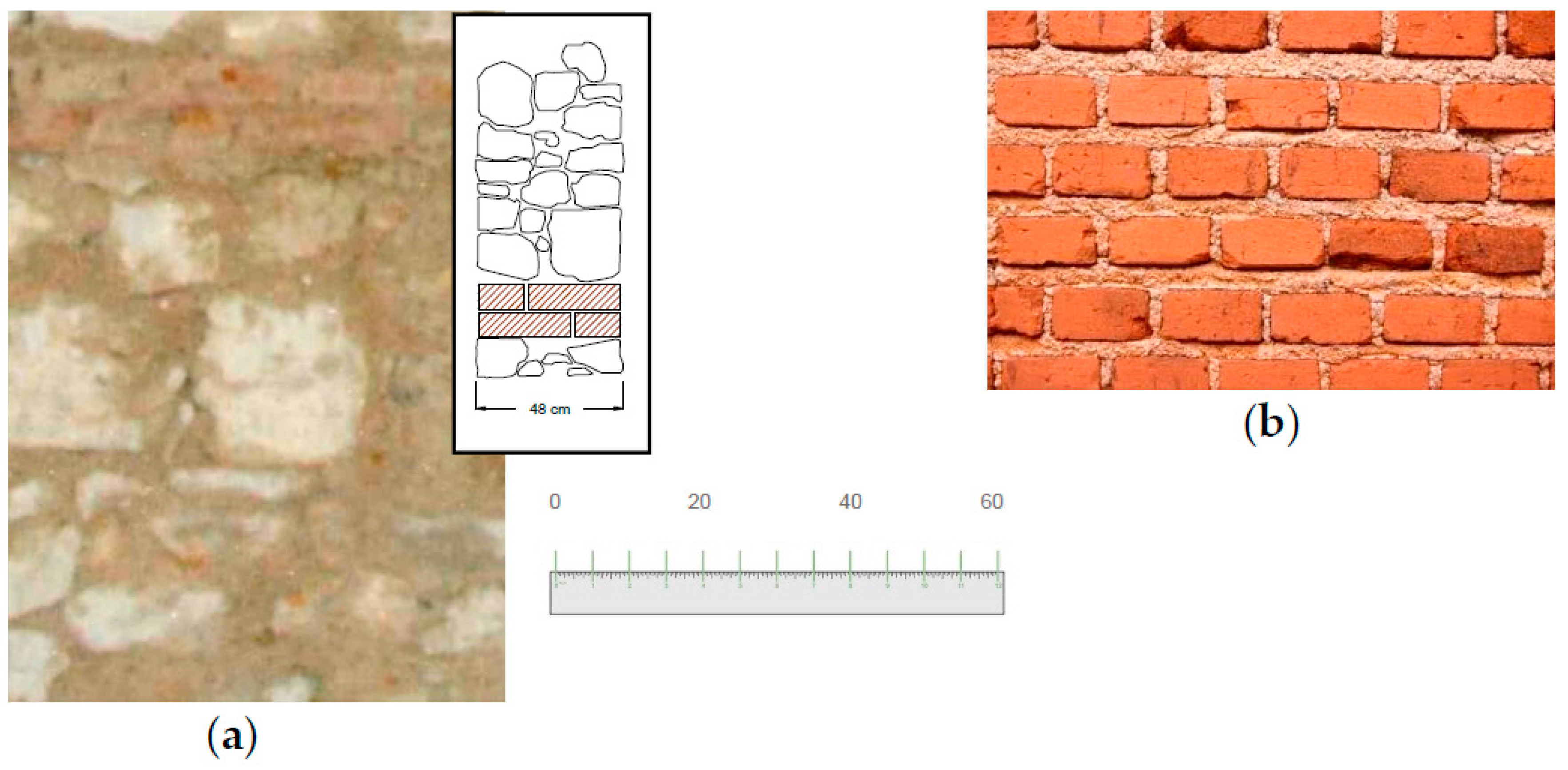
The buildings are comparatively simple functional structures built from locally available materials with a minimum of decoration. Walls were made of stones (Figure 2a, Figure 3a and Figure 4) or solid bricks (Figure 2b and Figure 3b). The stone panels, typically used for the ground floor walls, were approximately 45–70 cm thick and were made of similar barely-cut calcareous stones with a high weight density (approx. 2540 kg/m3, Coefficient of variation 14.1%). These were double-leaf walls, with no through stones between the leaves. Two courses of solid bricks were placed at regular intervals of 90–110 cm. The dimensions and the shape of the stones were also similar for the buildings: stones had a parallelepiped shape with longest dimensions of approx. 35–45 cm, placed horizontally and parallel to the plane of the wall.
Buildings Nos. 1 and 2 were also made of brickwork internal walls. Brickwork walls were made of solid hand-made bricks. The thickness was approx. 30 and 25 cm, and the bonding pattern was Header and Flemish for walls of Buildings Nos. 1 and 2, respectively. The respective compressive and bending strengths of the bricks were 28.2 and 6.85 MPa (for Building No. 1), and 24.1 and 6.19 MPa (for Building No. 2). All the interiors were made of plastered walls, and the buildings were constructed from masonry bonded with low-strength lime mortar.
2.2. The Render
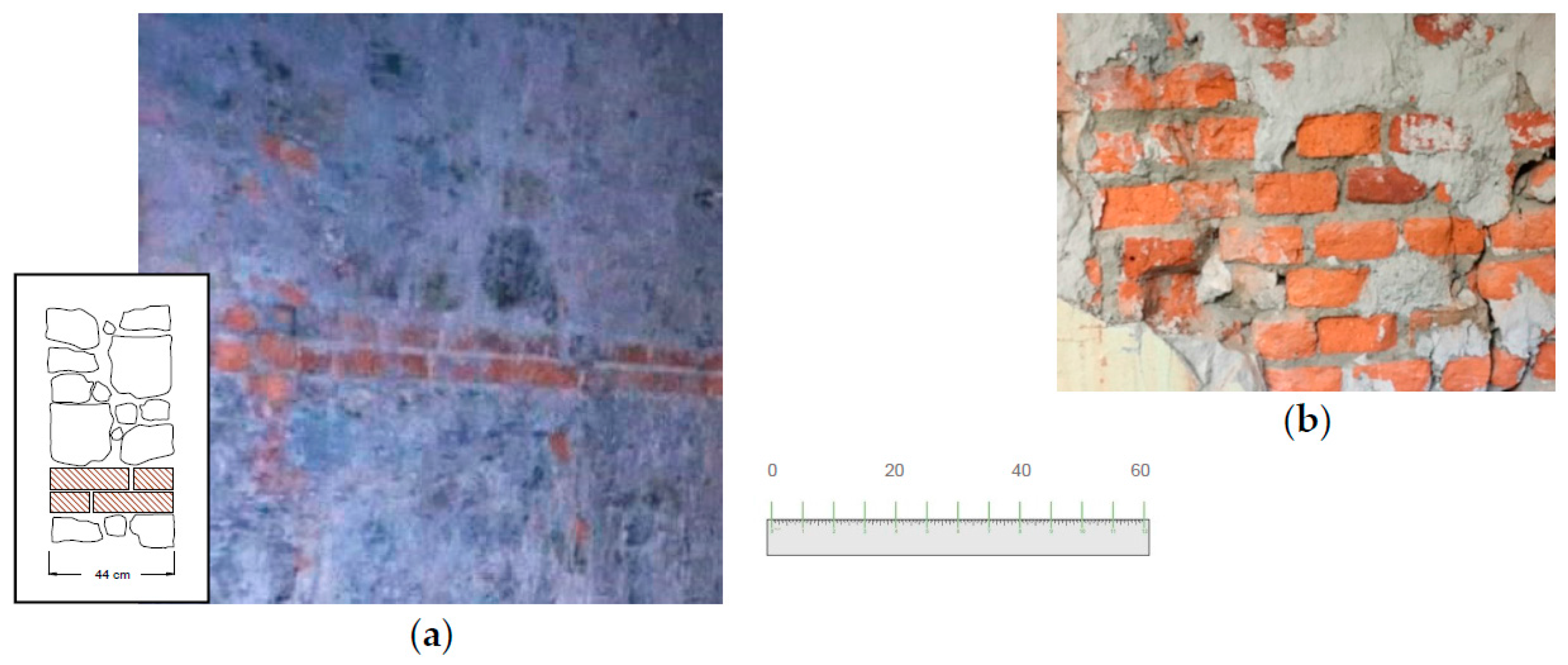
Today, the most commonly used materials for coating renders are ordinary Portland cement (OPC) with or without lime, which are mixed along with sand and water in various proportions to form a hardened adhesive material. Wall panels cut off from building No. 2 were rendered with a cement-based render. This was applied on both sides with a thickness of approx. 20 mm.
A Schmidt hammer was used to estimate the in-place strength of the mortar render. The test consisted of hitting the render with a spring-driven pin at a defined energy, and then the rebound value was measured. It is well known that the rebound depends on the surface hardness of the tested material and, by referring to conversion tables or formulas, the rebound result of the test can be used to determine its compressive strength. For a horizontal impact on a vertical surface, the probable cube strength of the material can be estimated using the conversion table of the producer (Schmidt Hammer Type N, Proceq) [32]. After discarding the highest and lowest values, results from 15 on-site tests showed an average value of the compressive strength of 18.8 MPa, with a coefficient of variation (CoV) of 23.3%. This value could be reduced to a characteristic strength fck of 150 mm diameter by 300 mm concrete cylinder of 12 MPa (strength class C12/15). The tensile strength could be finally estimated using [33]:
3. Test Layout
Full-scale wall panels were tested for compression and shear. Shear tests were carried out according to ASTM E-519 [34] and RILEM [35] standards. This standard provides a test method for the calculation of the shear strength of masonry assemblages. The test method involves the application of a diagonal compressive force at two opposite corners of the wall panel. Wall panels from the buildings were cut as close to 1800 × 900 mm and 1200 × 1200 mm as practical for compression and shear tests, respectively. All mechanical tests have been conducted on-site, given the difficulties in transporting the wall panels in an undamaged condition to a testing facility.
A total of twelve full-scale wall panels were tested. A single test was performed on each specimen. The naming convention for the tests was chosen in order to give each test a unique identity, facilitating their identification. The letter designation C and L was used for a compression and shear test, respectively. Consequently, test numbers correspond directly with the specimen numbers (from 1 to 12) and the letter designation B and S was employed for a brickwork or stone work panel, respectively. Panels from 1 to 4, from 9 to 11 and 12 were cut off from Building Nos. 1, 3 and 4, respectively (non-rendered panels) while the remaining four (from 5 to 8, cut off from Building No. 2) were tested before the removal of the render (Table 1).
3.1. Shear Tests
The shear strength τ0 was determined using the following equation [36]:
where ft is the masonry tensile strength, given by:
and Pmax is the maximum diagonal compressive load; A0 is the area of the horizontal wall section (thickness × width). The angular strain γ is given by:
where εc and εt are the compressive and tensile strains, respectively. These were recorded along the diagonals of both sides of the wall panel (side A and B), using the following:
where ΔLA,c and ΔLB,c are the shortenings of the two diagonals in compression on sides A and B, respectively, and LA,c and LB,c are the corresponding gage lengths. The letter designation “t” is used to identify elongations and gage lengths of the diagonals in traction.
The stiffness was measured using conventionally defined shear moduli. These were calculated as the slope of the secant line at Pmax and at 33% of the maximum diagonal load:
where Pi is the initial diagonal load in correspondence of zero-strain and τi is the corresponding shear stress value.
3.2. Compression Tests
A compression test was used to determine the behavior of the wall panels under crushing loads. The wall specimen was compressed and deformations at various loads were recorded and plotted as a stress-strain diagram. Compressive stress σ0 and vertical compressive strains εv were calculated using the following equations:
and
where Fmax is the maximum compression load, and A0 is the area of the horizontal cross section of the wall panel. For rendered panels, this value also included the area of the horizontal cross section of the cement-based rendering. The letter designations “A” and “B” were used to identify the two sides of a wall panel.
Young’s modulus was calculated using the following conventional formulation:
where σi is the initial normal stress in correspondence of zero-strain.
3.3. Instrumentation
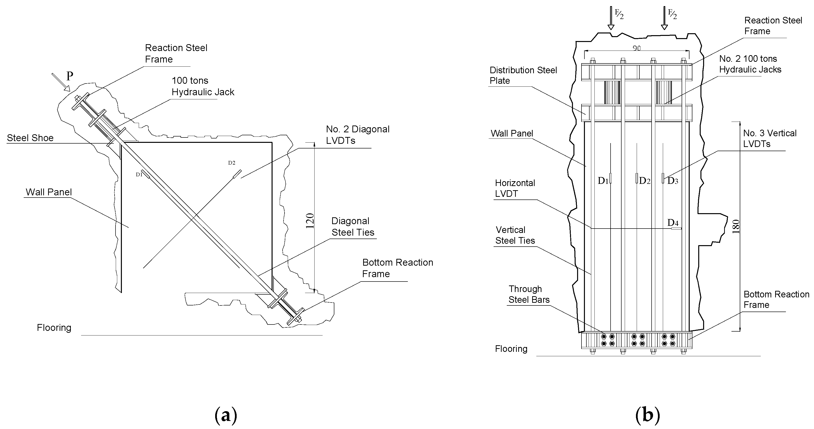
For both compression and shear tests, load was applied using manually controlled load steps. Wall specimens were subjected to cyclic loading by means of 100 tons-hydraulic jacks which were fixed to a steel reaction frame. A typical load history of a diagonal tension test is shown in Figure 5. All tests were carried out on-site. Figure 6 shows the location of either the instrument itself (hydraulic jacks, loading frames, etc.) or the attachment point to the wall panel for the instrumentation that was common to all specimens subjected to a compression or shear test, respectively.
4. Results and Discussion
4.1. Results and Analysis of Compression Tests
Four rectangular wall panels were tested for compression: two stone work and two brickwork panels. Table 2 shows the values of the maximum vertical forces recorded during the testing. The total number of the load cycles as well as maximum vertical displacement, Young’s moduli, E0.33 and Eu, and compressive strength, is given.
Non-rendered wall panels were loaded until vertical cracks formed in the mortar joints, then loading continued and the compressive strength was determined. This typical failure mode is shown in Figure 7a. For the stone panel, a compressive strength of 0.796 MPa was found and, for the brickwork one, a value of 1.84 MPa could be calculated. Corresponding strain values were found to be 0.00158 and 0.00146, respectively. The deformation response of both stone and brick masonry walls was incrementally nonlinear and dependant upon the level of the compressive load.
Table 2 also reports the test results for rendered wall panels. The failure mode of these panels was very similar to the one observed for non-rendered walls: the main difference was the progressive detachment of the cement-based render during the plastic non-linear phase of loading. Both the compressive strength and Young’s modulus values did not significantly differ to those tested without the cement-based render. The maximum increment in strength was 16% for brickwork panels and this can be considered within the normal inherent variation for historic masonry. It should be noted here that the compressive strength σ0 = Fmax/A0 was calculated by considering in A0 the cross sectional areas of both the render and panel. The limited effect of the render can be explained by considering the good mechanical properties of the masonry material in compression, not substantially different from those of the render.
Table 3 shows the default material properties of existing masonry obtained from the available Italian guideline [37]. By looking at the corresponding masonry category (Row 1: “Irregular stone masonry”; Row 6: “Solid brick masonry with lime mortar”), it can be noted that wall panels subjected to the compression test generally had ultimate strengths that are consistent with values suggested by the Italian guideline. A similar consideration can be made for the Young’s modulus. The values found for stone masonry (933 and 989 MPa) and brickwork (1554 and 1888 MPa) fall into the range suggested by the Italian guideline (690–1050 MPa and 1200–1800 MPa) for the corresponding masonry typologies.
The existence of a cement-based render seems to have little effect on the structural behavior of the wall, without affecting its load-capacity and deformation capacity. For these tests, a key-factor was the bond between the masonry substrate and the render. As cracking and debonding of the cement render occurred, the effect of the render became negligible.
4.2. Results and Analysis of Shear Tests
Eight square wall panels were tested in shear (diagonal tension test). Stone and brickwork panels were tested in both rendered and non-rendered conditions. Results of the shear tests are reported in Table 4.
Contrary to compression tests, ultimate strengths were noted to have significantly increased when a cement-based render was utilized (Figure 8). Interestingly, these shear strengths (τ0) were higher—on the order of 0.081 and 0.165 MPa for stone and brickwork panels, respectively—than was expected considering the existing literature. With regard to the softening branch of the response curves shown in Figure 8, limited qualitative information is available from the tests. Tests were carried out using hydraulic jacks with little control on the displacement rate. For stone non-rendered masonry panels, the maximum loads are similar in magnitude to the ultimate load (residual strength). This is typical for masonry of low quality [38]. The softening branch of the rendered stone and brick panels was slightly different with a larger reduction in strength.
The Italian Building Code (Guidelines [37]) and the long experience of the authors [13,14,22] demonstrate that the shear strength of an irregular double-leaf stone wall is rarely higher than 0.03–0.04 MPa. All un-rendered stone work panels exhibited a shear strength in the range of 0.022–0.036 MPa (Figure 9). The average value of the shear strength was for these panel 0.0283 MPa.
A similar comment could be made about the results of tests on brickwork panels. The results of the rendered panel is again significantly higher than expected. By comparing this result with the one for the un-rendered panel, it can be noted that the contribution of the cement-based render seems to be critical. Typical cyclic behaviour for both non-rendered and rendered wall panels is shown in Figure 8b. As can be seen from this figure, because of the cement-based render, panels cut off from Building No. 2 displayed small energy dissipation, significant strength (τ0) and stiffness (G0.33) increments compared to non-rendered panels. Despite a very similar masonry typology, the structural response of the panels was very different.
The predominant failure mode of rendered and non-rendered panels was in shear, which can be classified as a type of brittle tension failure with characteristic diagonal cracks along the diagonal in compression (Figure 10). Diagonal failure denoted tensile shear cracking at the center of the wall panel which afterwards began to behave as a rigid body, i.e., without further demolition of the wall specimen. The render did not detach from the masonry substrate during the test (Figure 10b).
Values of the shear stiffness and residual strength are also reported in Table 4. The cement-based render seems to have an effect on the stiffness of the panels (G0.33 and Gu values). Rendered panels exhibited a stiffness increase G0.33 by a factor of 21 and 8, for stone and brick panels, respectively.
5. Design
Test results have demonstrated that the shear strength can be affected by the cement-based render. A simplified approach to the problem can be made by considering the contribution of the cement-based render as a separate wall panel, and by calculating the lateral capacity of a rendered wall panel as the addition of the capacities of the URM wall and the render:
where Pwall is the lateral load-capacity of the URM wall panel and Prender is the lateral load capacity of the render. This design philosophy is based on limit-state design principles. By re-arranging Equations (2) and (3), it is possible to calculate the portion of diagonal load absorbed by the mortar:
where
and where Arender is the area of the of the horizontal cross section of the render (=1200 mm × the thickness of the render), and n is the number of sides were the render has been applied (1 or 2). By doing this, it is possible to develop an analytical formulation for the prediction of the lateral capacity of a wall, using the data obtained from the mechanical characterization of the render.
In Table 5, experimental results in terms of lateral load capacity are compared with theoretical ones, calculated from the tensile strength of the render (Equation (1)). It can be noted that the analytical formulation is able to capture the lateral capacity of a rendered wall with an acceptable error. It can be also noted that the analytical values of the lateral load capacity, using Equation (2), provide an overestimation of the load-capacity of the stone-panel. This can be explained by considering the assumptions of the limit-state analysis (perfect plastic material behavior).
By contrast, the theoretical value underestimates the lateral load capacity of the rendered brickwork wall. However, it should be pointed out that the theoretical wall capacity (Pwall) was calculated in Equation (15) using the shear strength τ0 of the corresponding non-rendered wall (test No. L-04-B). For this test the bonding pattern was “Header bond”, while for the rendered wall this was “Flemish bond”. Given the particular arrangement of the bricks, this system of header bonding is much weaker than Flemish again lateral in-plane loads [21,22].
A similar method was recently used by Gattesco and Boem [16]. By using a large amount of experimental results from laboratory tests, these researchers concluded that the theoretical formulation also overestimates the lateral capacity of a wall panel, when high-strength renders are used and underestimates it when low-strength renders are employed. In order to overcome these problems, the authors proposed to apply a modification factor defined as the ratio between the experimental lateral capacity and the value of the analytical prediction, using Equations (15) and (16):
where PRmax is the experimental value of the load lateral capacity of the rendered wall. The main limitation of the method used by Gattesco and Boem to calibrate the modification factor is that this has been done by only using laboratory tests and a limited number of mortar types. In detail, the shear strength of the URM wall panels is dramatically larger compared to the shear strength of stone masonry wall panels tested on-site. The Italian Building Code [37] provides a table for the shear strength of URM masonry with values ranging from 0.020 and 0.074 MPa, for rubble, irregular, peddle and barely cut stone masonry, while the shear strength of the URM stone masonry used by the authors ranged from 0.076 and 0.175 MPa.
However it must be concluded that this method seems to be the most appropriate for design purposes. Based on this, it is necessary to re-calibrate the modification factor, given by Equation (17), by including on-site test results. Clearly the available data are not sufficient and more tests are needed to clarify the force transfer from the masonry substrate to the render under the different test configurations and a deeper study should be developed. However an emerging trend was noted, indicating the effects of cement-based renders applied to historic wall panels.
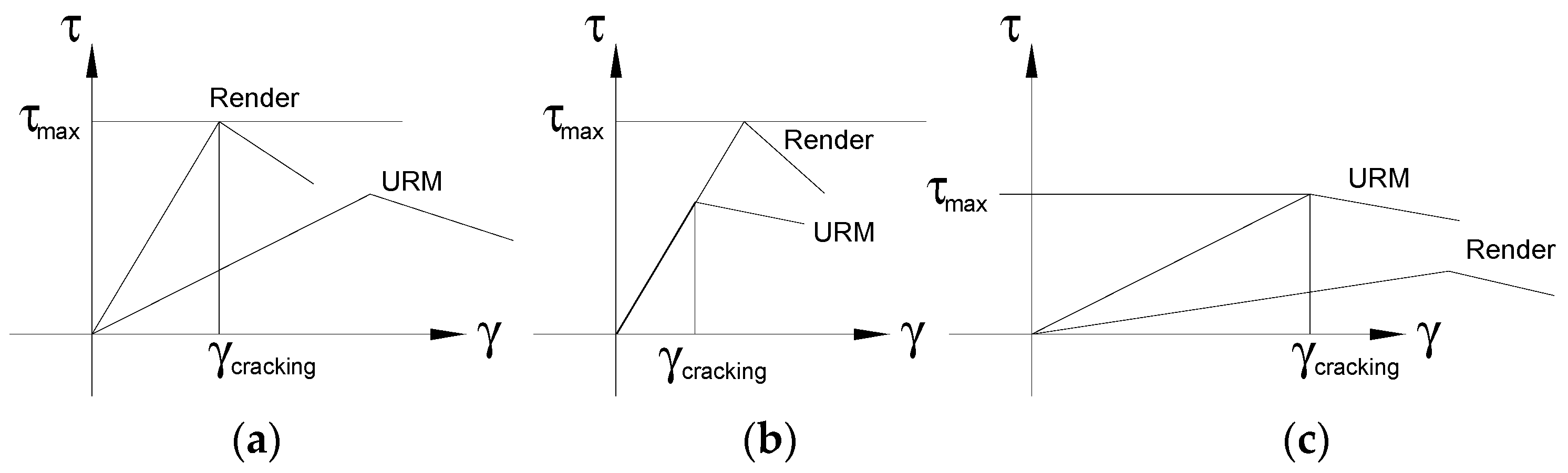
By assuming perfect bonding between the masonry material and the render, Equation (2) can be used only if perfect plastic behaviour is assumed for both the masonry and render materials. If this cannot be assumed and the shear moduli of the two materials are very different, Equation (14) cannot be used for design purposes, as it overestimates the load-capacity of the rendered wall. Figure 11 shows three different cases. By considering a limit shear strain γcracking, it is evident that only a portion of the overall capacity of one of the two materials can be exploited within the elastic phase.
Clearly, the error produced by using Equation (14) for non-perfect-plastic elastic materials depends on how scattered the τ-γ plots are (and therefore the ratio between the shear moduli), the shear strengths τ0 of the two materials and the post-elastic behaviour. This can partially explain the overestimation of the lateral capacity found for stone panels.
6. Conclusions
URM masonry buildings tend to perform poorly in earthquakes owing to the low shear strength of the masonry material and the inconsistent lime-based mortar used for construction in the past. The use of rubble or barely cut stone, the absence of adequate connections between wall leaves, the lack of skilled masons and adequate resources were the main causes for the low quality of historic constructions.
Knowledge of the mechanical characteristics of URM masonry is of critical importance for any type of seismic analysis or design of a retrofitting intervention. Several researchers have studied and attempted to measure the mechanical properties of historic masonry, by considering different constituent materials (mortar and blocks), arrangements, dimensions and shapes of the blocks (typically bricks or stones), levels of connection between the wall leaves. Historic walls are often rendered with cement-based renders. However, the effect of these renders was not studied in the past.
Mechanical on-site tests were conducted on twelve wall panels subjected to in-plane shear or compressive loading. All wall panels were made of a lime-based putty and irregular stone masonry. These were tested with two different configurations: before removal of the cement-based render or after. Only static tests have been performed to date to estimate the static ultimate capacity and deformation response of the wall panels. Compressive and in-plane shear loads were applied in cycles to make sure that the transient phase during which the wall panels are transferred between the elastic and plastic strain zone was accurately recorded and the effect of the cement-based render adequately analyzed.
In conclusion, it has been demonstrated that:
- The lateral load-capacity and shear stiffness of historic wall panels can increase considerably as the walls are rendered with a cement-based mortar; significant shear strength and stiffness increments were observed for barely-cut (irregular) double-leaf stone and brickwork panels;
- The application of a cement-based render did not significantly alter the failure mode of the wall panels, both under shear and compressive loading;
- Limited effect was produced by the render when the wall specimens were tested in compression. For these tests, the behavior of the wall panels was governed by the bond between the masonry and the render. As cracking and debonding of the cement render occurred, the positive effect of the render, both in terms of load capacity and stiffness, became negligible;
- With regard to the shear tests, the bonding between renders and masonry substrate remained effective for the entire duration of the test. Shear failure occurred with characteristic diagonal cracks along the diagonal in compression. If maintaining the bond is critical for the performance of a wall panel, shear modulus of the render material should not be substantially different from the one of the masonry material.
- A main limitation of this study is that masonry specimens were cut from different buildings, making a direct comparison difficult, given the intrinsic variability in mechanical properties of historic masonry and the different conditions of conservation of the buildings. However, an emerging trend was noted, indicating the effects of a cement-based render applied to historic wall panels.
- Finally, more systematic tests are needed to clarify the force transfer from the masonry substrate to the render under different test configurations, and a more in-depth study should be conducted. Tests should be carried out on purposely constructed masonry specimens, having controlled and reproducible properties, to obtain more conclusive data.
Acknowledgments
The authors wish to extend their appreciation to Alessio Molinari who, under the authors direction, carried out the tests, and to Letizia Caselli from Azienda USL Toscana Nord Ovest. The authors are also grateful for continuing support from colleagues in the Engineering Department.
Author Contributions
Antonio Borri conceived and designed the experiments; Romina Sisti performed the experiments; Marco Corradi analyzed the data and wrote the paper.
Conflicts of Interest
The authors declare no conflict of interest.
References
- Corradi, M.; Osofero, A.I.; Coventry, K.; Richardson, A.E.; Udeaja, C.; Vo, T. Analysis and classification of historic construction within the north-east of England. In Proceedings of the 16th International Conference Structural Faults & Repair-2014, London, UK, 8–10 July 2014. [Google Scholar]
- Morandi, P.; Magenes, G.; Albanesi, L. Mechanical characterization of different typologies of masonry made with thin shell/web clay units. In Proceedings of the 12th Canadian Masonry Symposium, Vancouver, BC, Canada, 2–5 June 2013. [Google Scholar]
- Mastrodicasa, S. Dissesti Statici Delle Strutture Edilizie: Diagnosi, Consolidamento, Istituzioni Teoriche; Hoepli: Milan, Italy, 1978. (In Italian) [Google Scholar]
- Magenes, G.; Penna, A.; Galasco, A.; Rota, M. Experimental characterization of stone masonry mechanical properties. In Proceedings of the 8th International Masonry Conference, Dresden, Germany, 4–7 July 2010. [Google Scholar]
- Valluzzi, M.R.; Da Porto, F.; Modena, C. Behavior and modeling of strengthened three-leaf stone masonry walls. Mater. Struct. 2004, 37, 184–192. [Google Scholar] [CrossRef]
- Binda, L.; Cardani, G.; Saisi, A. A classification of structures and masonries for the adequate choice of repair. In Proceedings of the International RILEM Workshop on Repair for Historic Masonry, Delft, The Netherlands, 26–28 January 2005. [Google Scholar]
- Giuffrè, A. Letture Sulla Meccanica Delle Murature storiche; Kappa: Rome, Italy, 1999. (In Italian) [Google Scholar]
- Benedetti, A. Interaction of shear and flexural collapse modes in the assessment of in plane capacity of masonry walls. In Proceedings of the 12th Canadian Masonry Symposium, Vancouver, BC, Canada, 2–5 June 2013. [Google Scholar]
- Cardoso, R.; Lopes, M.; Bento, R. Seismic evaluation of old masonry buildings. Part I: Method description and application to a case-study. Eng. Struct. 2005, 27, 2024–2035. [Google Scholar] [CrossRef]
- D’Ayala, D.; Speranza, E. Definition of collapse mechanisms and seismic vulnerability of historic masonry buildings. Earthq. Spe. 2003, 19, 479–509. [Google Scholar] [CrossRef]
- D’Ayala, D.F.; Paganoni, S. Assessment and analysis of damage in L’Aquila historic city centre after 6th April 2009. Bull. Earthq. Eng. 2011, 9, 81–104. [Google Scholar] [CrossRef]
- Penna, A.; Morandi, P.; Rota, M.; Manzini, C.F.; Da Porto, F.; Magenes, G. Performance of masonry buildings during the Emilia 2012 earthquake. Bull. Earthq. Eng. 2014, 12, 2255–2273. [Google Scholar] [CrossRef]
- Borri, A.; Castori, G.; Corradi, M.; Giannantoni, A.; Speranzini, E. A reinforced repointing grid for strengthening historic stone masonry walls. In Proceedings of the 8th International Masonry Conference, Dresden, Germany, 4–7 July 2010. [Google Scholar]
- Corradi, M.; Borri, A.; Vignoli, A. Seismic upgrading of masonry structures with FRP. In Proceedings of the 7th International Conference on Inspection Appraisal Repairs and Maintenance of buildings and structures, Nottingham, UK, 11–13 September 2001. [Google Scholar]
- Cattari, S.; Degli Abbati, S.; Ferretti, D.; Lagomarsino, S.; Ottonelli, D.; Tralli, A. Damage assessment of fortresses after the 2012 Emilia earthquake (Italy). Bull. Earthq. Eng. 2014, 12, 2333–2365. [Google Scholar] [CrossRef]
- Gattesco, N.; Boem, I. Experimental and analytical study to evaluate the effectiveness of an in-plane reinforcement for masonry walls using GFRP meshes. Constr. Build. Mater. 2015, 88, 94–104. [Google Scholar] [CrossRef]
- Coburn, A.; Spence, R. Earthquake Protection; Wiley and Sons: Chichester, UK, 1992. [Google Scholar]
- Lourenço, P.B.; Mendesa, N.; Ramosa, L.F.; Oliveira, D.V. Analysis of masonry structures without box behavior. Int. J. Arch. Herit. 2011, 5, 369–382. [Google Scholar] [CrossRef] [Green Version]
- Galati, N.; Tumialan, G.; Nanni, A. Strengthening with FRP bars of URM walls subject to out-of-plane loads. Constr. Build. Mater. 2006, 20, 101–110. [Google Scholar] [CrossRef]
- Vintzileou, E.; Miltiadou-Fezans, A. Mechanical properties of three-leaf stone masonry grouted with ternary or hydraulic lime-based grouts. Eng. Struct. 2008, 30, 2265–2276. [Google Scholar] [CrossRef]
- Borri, A.; Castori, G.; Corradi, M. Shear behavior of unreinforced and reinforced masonry panels subjected to in-situ diagonal compression tests. Int. J. Arch. Herit. 2014, 9, 913–927. [Google Scholar] [CrossRef]
- Corradi, M.; Tedeschi, C.; Binda, L.; Borri, A. Experimental evaluation of shear and compression strength of masonry wall before and after reinforcement: Deep repointing. Constr. Build. Mater. 2008, 22, 463–472. [Google Scholar] [CrossRef]
- Corradi, M.; Borri, A.; Vignoli, A. Experimental evaluation of in-plane shear behavior of masonry walls retrofitted using conventional and innovative methods. Mason. Int. 2008, 21, 29–42. [Google Scholar]
- Stratford, T.; Pascale, G.; Manfroni, O.; Bonfiglioli, B. Shear strengthening masonry panels with sheet glass–fiber reinforced polymer. J. Compos. Constr. 2004, 8, 434–443. [Google Scholar] [CrossRef]
- Marcari, G.; Manfredi, G.; Prota, A.; Pecce, M. In-plane shear performance of masonry panels strengthened with FRP. Compos. Part B 2007, 38, 887–901. [Google Scholar] [CrossRef]
- El Gawady, M.A.; Lestuzzi, P.; Badoux, M. Static cyclic response of masonry walls retrofitted with fiber-reinforced polymers. J. Compos. Constr. 2007, 11, 50–61. [Google Scholar] [CrossRef]
- Roca, P.; Araiza, G. Shear response of brick masonry small assemblages strengthened with bonded FRP laminates for in-plane reinforcement. Constr. Build. Mater. 2010, 24, 1372–1384. [Google Scholar] [CrossRef]
- Foti, D.; Vacca, S. Mechanical behavior of concrete columns reinforced with rheoplastic mortar. Mater. Constr. 2013, 63, 267–282. [Google Scholar] [CrossRef]
- Ivorra, S.; Bru, D.; Galvan, A.; Silvestri, S.; Apera, C.; Foti, D. TRM Reinforcement of masonry specimens for seismic areas. Int. J. Saf. Secur. Eng. 2017, 7, 463–474. [Google Scholar]
- Neville, A.M. Properties of Concrete, 5th ed.; Pearson Education Limited: Harlow, UK, 2011. [Google Scholar]
- Borri, A.; Corradi, M.; Castori, G.; De Maria, A. A method for the analysis and classification of historic masonry. Bull. Earthq. Eng. 2015, 13, 1–19. [Google Scholar] [CrossRef]
- British Standard BS EN 12504-2. Testing Concrete in Structures. Non-Destructive Testing. Determination of Rebound Number. 2012. Available online: https://shop.bsigroup.com/ (accessed on 11 August 2016).
- Eurocode 2: Design of Concrete Structures—Part 1-1: General Rules and Rules for Buildings. 1992. Available online: https://landingpage.bsigroup.com/LandingPage/Undated?UPI=000000000030286962 (accessed on 11 January 2018).
- American Society for Testing and Materials (ASTM). E519 Standard Test Method for Diagonal Tension (Shear) in Masonry Assemblages. In Annual Book of ASTM Standards; ASTM International: West Conshohocken, PA, USA, 2010. [Google Scholar]
- RILEM TC. 76-LUM. Diagonal tensile strength tests of small wall specimens. In RILEM, Recommendations for the Testing and Use of Constructions Materials; E&FN SPON: London, UK, 1994; pp. 488–489. [Google Scholar]
- Turnšek, V.; Čačovič, F. Some experimental results on the strength of brick masonry walls. In Proceedings of the 2nd International brick Masonry Conference, Stoke-on-Trent, UK, 12–15 April 1970. [Google Scholar]
- Italian Ministry of Infrastructures and Transportation. Istruzioni per L’applicazione Delle «Nuove Norme Tecniche per le Costruzioni» di Cui al Decreto Ministeriale 14 Gennaio 2008; Italian Building Code, Circ. 02.02.2009, n. 617; Italian Ministry of Infrastructures and Transportation: Rome, Italy, 2009. (In Italian)
- Benedetti, D.; Benzoni, G.M. Esperienze a taglio su pannelli in tufo. Ingegneria Sismica 1985, 2, 15–24. [Google Scholar]
Figure 1.
The four historic buildings where tests were carried out: (a) Building No. 1 (located in Belfiore, Foligno, Italy); (b) Building No. 2 (located in Lucca, Italy); (c) Building No. 3 (located in Porta Napoli, L’Aquila, Italy); (d) Building No. 4 (located in Via 20 Settembre, L’Aquila, Italy).
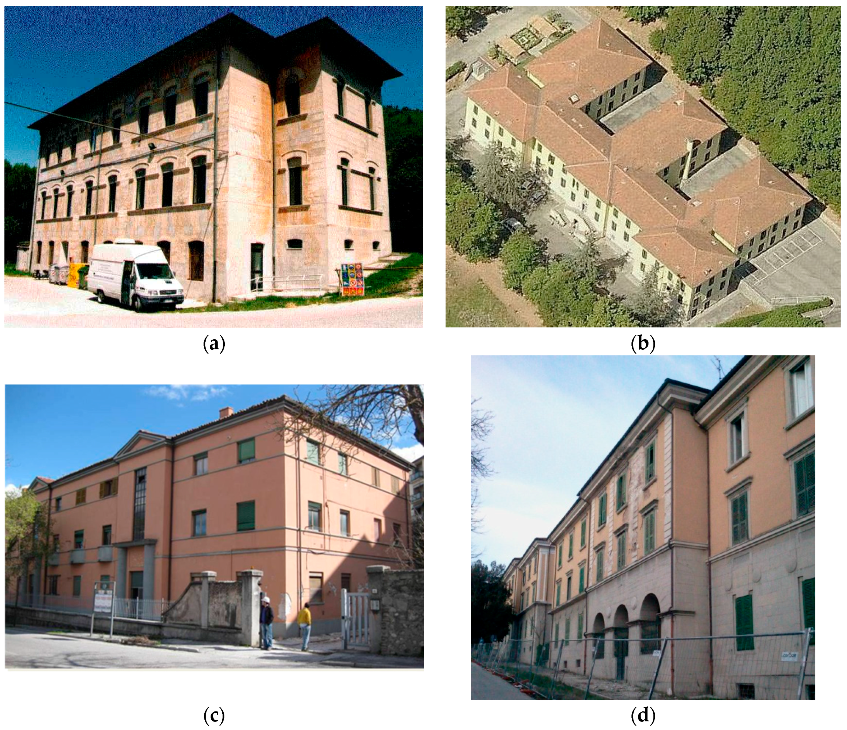
Figure 2.
Masonry typologies of Building No. 1: (a) Stone work; (b) Brickwork, [dimensions in cm].

Figure 3.
Masonry typologies of Building No. 2: (a) Stone work; (b) Brickwork, [dimensions in cm].

Figure 4.
Stone masonry typologies: (a) Building No. 3; (b) Building No. 4.
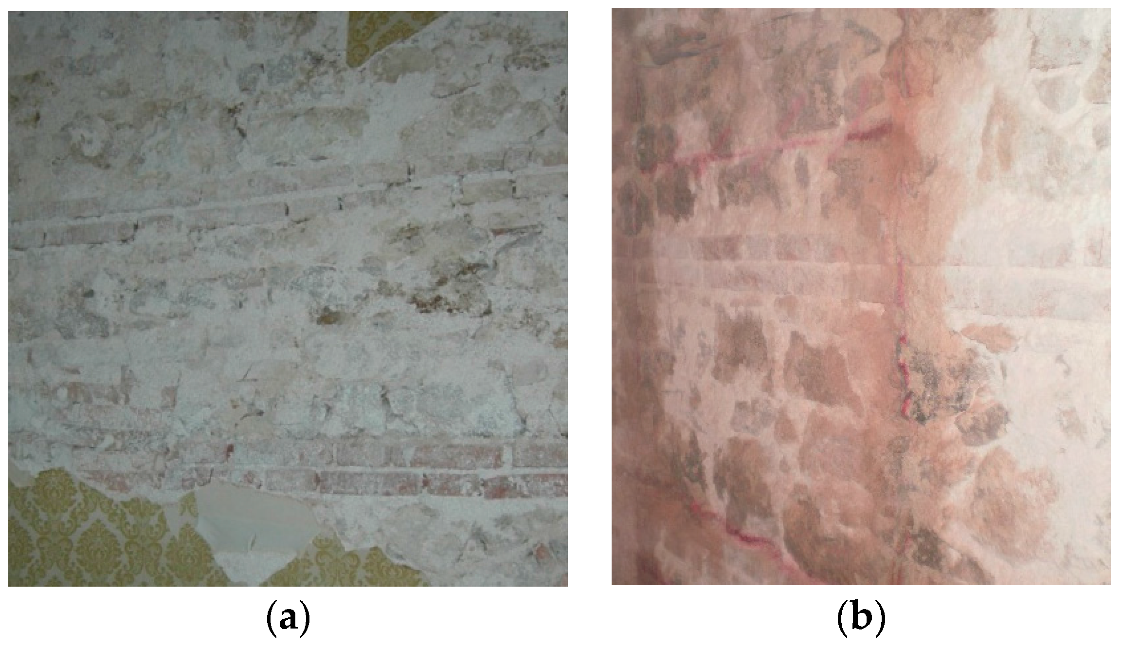
Figure 5.
Typical load history of a diagonal tension test.
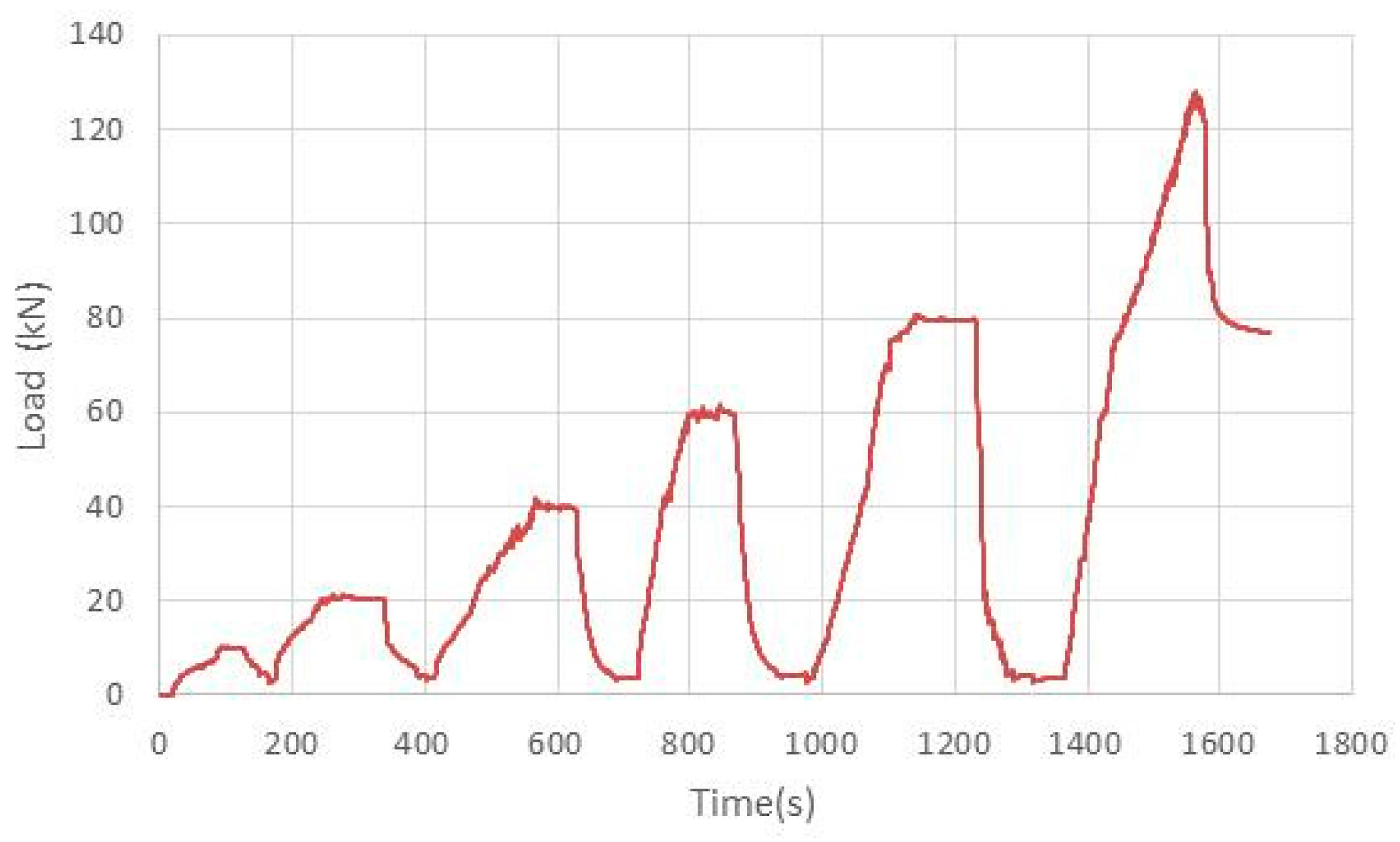
Figure 6.
Instrumentation and test layout: (a) Diagonal tension test; (b) Compression test [dimensions in cm].
Figure 6.
Instrumentation and test layout: (a) Diagonal tension test; (b) Compression test [dimensions in cm].

Figure 7.
Compression tests: (a) C-01-S; (b) C-06-B.
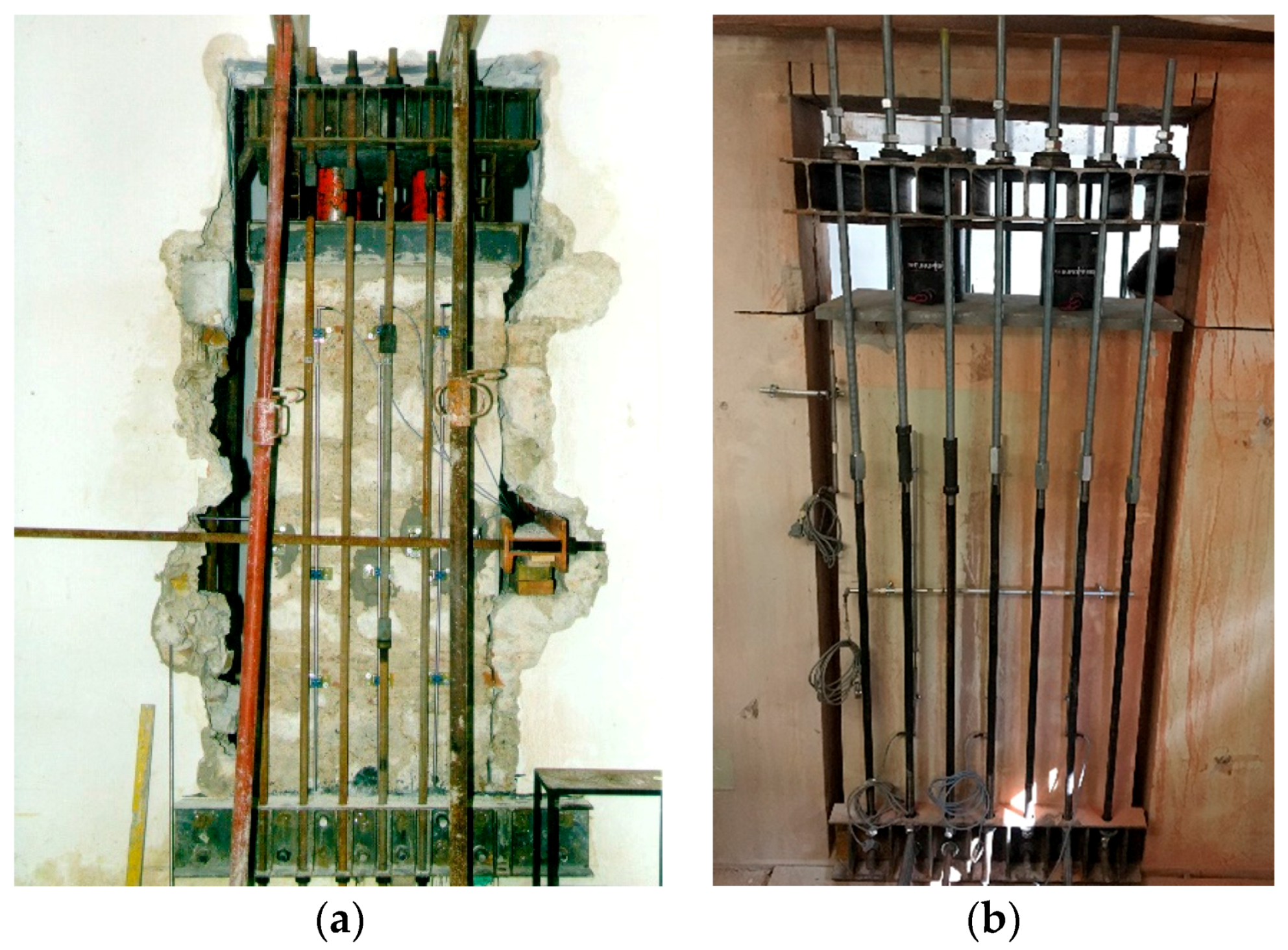
Figure 8.
Shear tests carried out on panels cut off from Building No. 1 (non-rendered panels) and 2 (rendered panels): (a) Stone work panels; (b) Brickwork panels.
Figure 8.
Shear tests carried out on panels cut off from Building No. 1 (non-rendered panels) and 2 (rendered panels): (a) Stone work panels; (b) Brickwork panels.
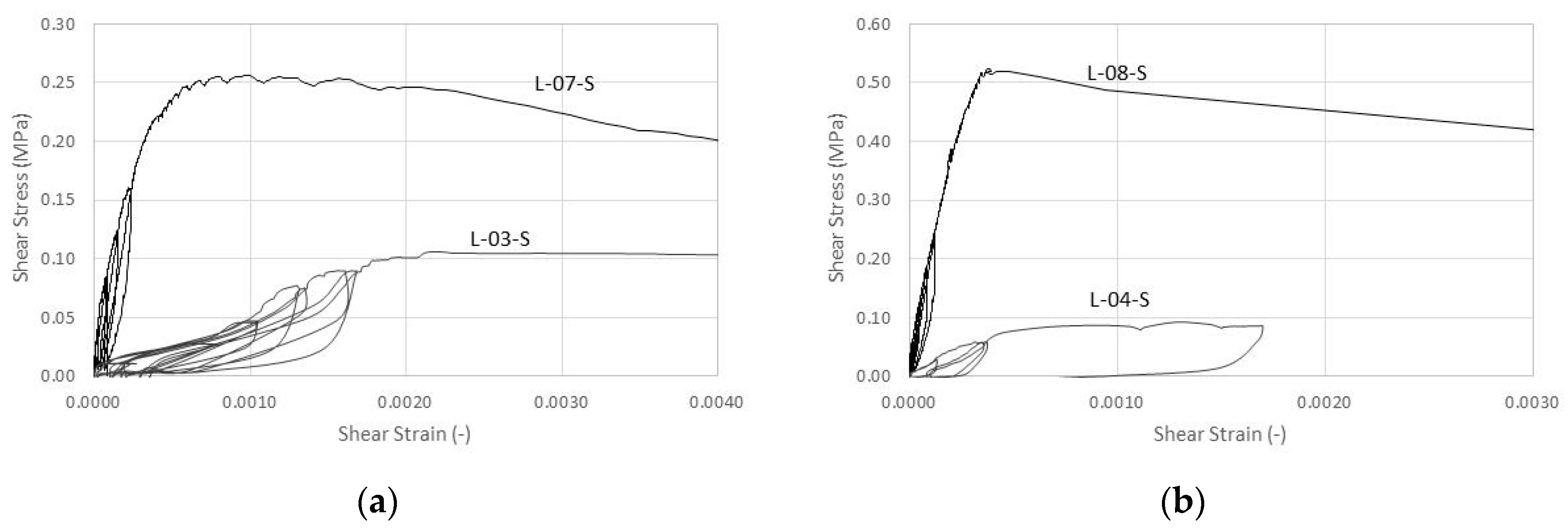
Figure 9.
Shear tests carried out on stone work panels cut off from Building No. 2 (rendered panels) and Nos. 3 and 4 (non-rendered).
Figure 9.
Shear tests carried out on stone work panels cut off from Building No. 2 (rendered panels) and Nos. 3 and 4 (non-rendered).
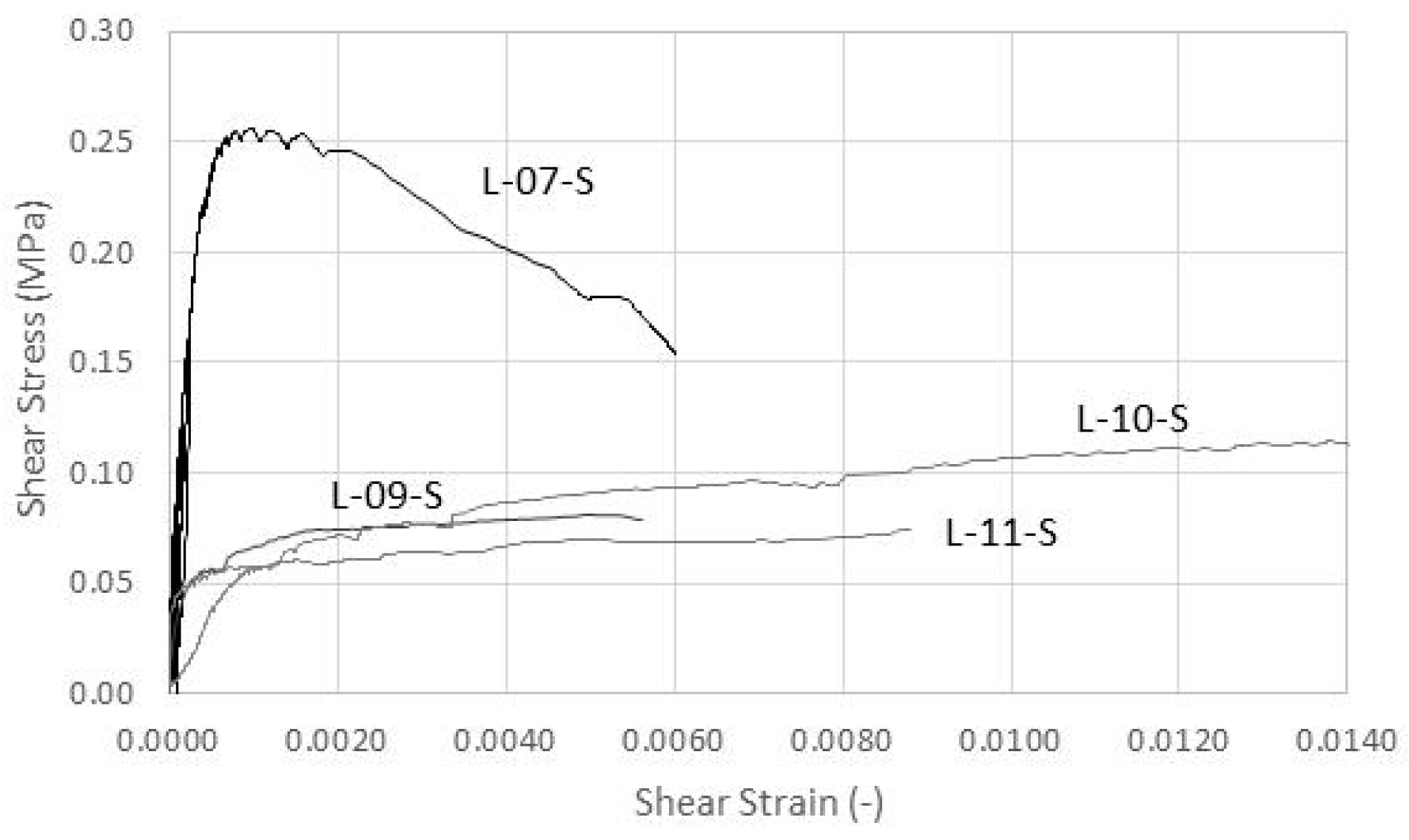
Figure 10.
Shear tests (rendered wall panels): (a) L-07-S; (b) L-08-B.
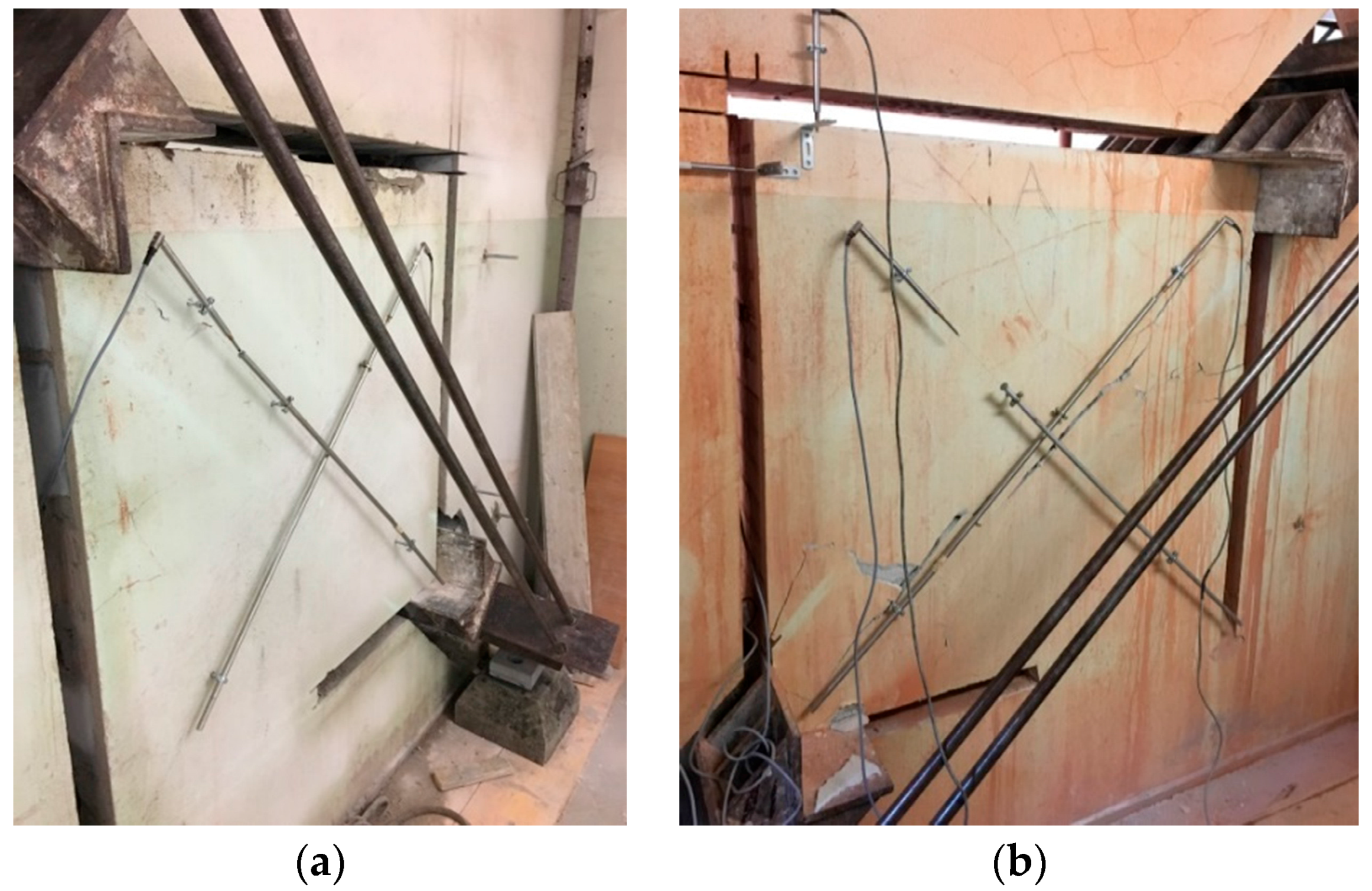
Figure 11.
Effect of non-perfect plastic behavior: (a) typical case for high-strength (cement-based) render; (b) typical case of a lime-based render; (c) typical case of low-strength (i.e., soft thermal-insulating coating).
Figure 11.
Effect of non-perfect plastic behavior: (a) typical case for high-strength (cement-based) render; (b) typical case of a lime-based render; (c) typical case of low-strength (i.e., soft thermal-insulating coating).


Table 1.
Test Matrix.
| Code | Test Type | Walling Material | Render | Code | Test Type | Walling Material | Render |
|---|---|---|---|---|---|---|---|
| C-01-S | Compression | Stone | No | L-07-S | Shear | Stone | Yes |
| C-02-B | Compression | Brick | No | L-08-B | Shear | Brick | Yes |
| L-03-S | Shear | Stone | No | L-09-S | Shear | Stone | No |
| L-04-B | Shear | Brick | No | L-10-S | Shear | Stone | No |
| C-05-S | Compression | Stone | Yes | L-11-S | Shear | Stone | No |
| C-06-B | Compression | Brick | Yes | L-12-S | Shear | Stone | No |
Table 2.
Results of compression tests.
| Code | Load-Capacity Fmax (kN) | No. of Cycles | Compressive Strength σ0 (MPa) | E0.33 (MPa) | Eu (MPa) | Strain at σ0 (−) | Residual Strength at εv,max (MPa) |
|---|---|---|---|---|---|---|---|
| C-01-S | 343.35 | 4 | 0.796 | 933 | 488 | 0.00158 | 0.792 |
| C-02-B | 496.77 | 6 | 1.84 | 1554 | 395 | 0.00451 | 1.81 |
| C-05-S * | 408.04 | 4 | 0.830 | 989 | 534 | 0.00146 | 0.781 |
| C-06-B * | 538.21 | 7 | 2.14 | 1888 | 488 | 0.00424 | 1.96 |
* Rendered wall panels.
Table 3.
Italian Standard (2009): masonry mechanical properties.
| Masonry Typology | Compressive Strength σ0 (MPa) | Shear Strength τ0 (MPa) | Young’s Modulus E (MPa) | Shear Modulus G (MPa) |
|---|---|---|---|---|
| min–max | min–max | min–max | min–max | |
| Stone masonry (pebbles, irregular stone) | 1.0–1.8 | 0.020–0.032 | 690–1050 | 230–350 |
| Barely cut stone masonry with infill core | 2.0–3.0 | 0.035–0.051 | 1020–1440 | 340–480 |
| Properly dressed stone masonry | 2.6–3.8 | 0.056–0.074 | 1500–1980 | 500–660 |
| Soft stone masonry (tuff, limestone, etc.) | 1.4–2.4 | 0.028–0.042 | 900–1260 | 300–420 |
| Perfectly cut stone masonry | 6.0–8.0 | 0.090–0.120 | 2400–3200 | 780–940 |
| Solid brick masonry with lime mortar | 2.4–4.0 | 0.060–0.090 | 1200–1800 | 400–600 |
| Clay hollow brick with cement mortar | 5.0–8.0 | 0.240–0.320 | 3500–5600 | 875–1400 |
Table 4.
Results of shear tests.
| Code | Load-Capacity Pmax (kN) | Shear Strength τ0 (MPa) | G0.33 (MPa) | Gu (MPa) | Strain γ at τ0 (−) | Residual Strength at γmax (MPa) |
|---|---|---|---|---|---|---|
| L-03-S | 58.81 | 0.0337 | 44.8 | 48.0 | 0.00221 | 0.0254 |
| L-04-B | 34.31 | 0.0317 | 248 | 38.8 | 0.00240 | 0.0263 |
| L-07-S * | 127.92 | 0.0813 | 940 | 317 | 0.000772 | 0.0514 |
| L-08-B * | 172.47 | 0.1655 | 1986 | 1329 | 0.000375 | 0.0257 |
| L-09-S | 43.55 | 0.0257 | 411 | 16.5 | 0.00494 | 0.0244 |
| L-10-S | 60.74 | 0.0363 | 75.9 | 8.31 | 0.01373 | 0.0356 |
| L-11-S | 39.02 | 0.0236 | n.a. | 8.44 | 0.00869 | 0.0233 |
| L-12-S | 61.71 | 0.0220 | n.a. | 9.24 | 0.00941 | 0.0217 |
* Rendered wall panels.
Table 5.
Results of shear tests.
| Code | Experimental Load-Capacity Pmax (kN) | Theoretical Wall Pwall (kN) | Theoretical Render Prender (kN) | Theoretical Pmax (kN) |
|---|---|---|---|---|
| L-07-S | 127.92 | 49.01 | 100.47 | 149.49 |
| L-08-B | 172.47 | 28.59 | 129.06 |
© 2018 by the authors. Licensee MDPI, Basel, Switzerland. This article is an open access article distributed under the terms and conditions of the Creative Commons Attribution (CC BY) license (http://creativecommons.org/licenses/by/4.0/).
Share and Cite
MDPI and ACS Style
Corradi, M.; Sisti, R.; Borri, A. Effect of Thin Cement-Based Renders on the Structural Response of Masonry Wall Panels. Appl. Sci. 2018, 8, 98. https://doi.org/10.3390/app8010098
AMA Style
Corradi M, Sisti R, Borri A. Effect of Thin Cement-Based Renders on the Structural Response of Masonry Wall Panels. Applied Sciences. 2018; 8(1):98. https://doi.org/10.3390/app8010098
Chicago/Turabian StyleCorradi, Marco, Romina Sisti, and Antonio Borri. 2018. "Effect of Thin Cement-Based Renders on the Structural Response of Masonry Wall Panels" Applied Sciences 8, no. 1: 98. https://doi.org/10.3390/app8010098
Note that from the first issue of 2016, this journal uses article numbers instead of page numbers. See further details here.