Experimental Study on Milling CFRP with Staggered PCD Cutter

School of Mechanical and Power Engineering, Harbin University of Science and Technology, 150080 Harbin, China
*
Author to whom correspondence should be addressed.
Appl. Sci. 2017, 7(9), 934; https://doi.org/10.3390/app7090934
Submission received: 31 July 2017
/
Revised: 31 August 2017
/
Accepted: 7 September 2017
/
Published: 11 September 2017
Abstract
:Carbon fiber reinforced plastics (CFRP) have good physical properties, such as high specific strength and high specific modulus. However, cutting delamination, tearing and burr, etc. often occur in the machining process of CFRP, which results in the uncontrollability of machining surface quality and serious tool wear. In this paper, milling of CFRP with a staggered cutter was carried out, the cutting-edge radius was investigated in order to characterize the tool wear; the effect of the cutting-edge wear radius on the milling force and surface quality was found, and the formation mechanisms of the 3D surface topography and surface defects were analyzed under the wear state. Experimental results showed that the wear of the staggered PCD cutter was mainly concentrated in the cutting-edge area. With the increase in milling length, the radius of cutting edge gradually became largeer under the action of abrasive wear mechanism, and the flank wear was not obvious. With the intension of tool wear, milling force gradually increased and the machining surface quality of the CFRP deteriorated distinctly, i.e., defects such as bare fiber fracture, groove and hole appeared, and burrs were gradually generated on the workpiece surface. Finally, through a comparative analysis of cutting performance, it was found that the staggered PCD cutter possessed better performance for wear resistance and burr suppression than the straight-teeth cutter. This finding can provide theoretical and technical support for improving the machining quality of carbon fiber composite materials.

1. Introduction
Carbon fiber reinforced plastic (CFRP) is widely used in such fields as aviation equipment, space vehicles, new weapons, etc. due to its excellent physical properties, such as high specific strength, high specific modulus and fatigue resistance, etc. [1,2]. However, with higher and higher demand for the processing and assembly of high-modulus CFRP in the industrial field, the problem of cutting CFRP becomes increasingly salient. For instance, the control of such defects as cutting delamination, tearing and burr etc. [3], and the improvement of tool durability, have become key limitations in the application of high-quality machining technology of CFRP materials.
A great deal of research on the cutting technology of CFRP has been carried out by scholars at home and abroad. Hintze et al. [4] investigated the occurrence reasons and extension law of cutting delamination through an experiment in which CFRP was milled using a two-flute PCD cutter, and the results showed that the delamination was highly dependent on the fiber orientation and tool edge sharpness. Moreover, the occurrence zone, diffusion zone and non-diffusion zone of defects were divided. Karpat et al. [5] used two different PCD cutters to mill unidirectional CFRP in tests, based on which the milling force prediction model was established, and the influence law of milling force on machining surface quality was obtained. Khairusshima et al. [6] studied the tool wear forms under various cooling conditions, and the results indicated that air cooling conditions can effectively minimize the heat generated in processing and the area of the tool wear zone, and prolong tool life. Colak et al. [7] carried out the experiment of milling CFRP using tools coated with diamond, and found that smaller milling forces and greater machining surface quality is satisfactory under the high-speed and low-feed cutting conditions. Gao et al. [8] established a 3D finite element model for cutting unidirectional CFRP, and the simulation results showed that fiber orientation angle, cutting depth and cutting speed are the main influential factors of milling force and surface roughness. Chibane et al. [9] conducted an experimental study on milling CFRP with a PCD cutter, and established the milling parameter optimization model for machining surface quality. Haddad et al. [10,11] carried out a test in which milling of CFRP was performed with a coated carbide tool, and investigated the influential mechanism of cutting parameters on cutting force, cutting temperature and machining surface quality. Meanwhile, the finite element method was used to predict cutting force and surface roughness. Davim et al. [12,13,14,15,16] conducted relative studies on the machining performance of the composites and optimization of cutting parameters.
In conclusion, the current research on milling CFRP mainly focuses on the cutting mechanism and machining surface quality [17,18,19,20], and cutting tools are mostly straight-teeth PCD or coated with carbide diamond [21,22]. Compared with the straight-teeth tools, staggered cutters have the advantages of reducing cutting resistance and restraining burr formation through bidirectional alternate inclination angle structure in the process of cutting CFRP, which has attracted significant attention from researchers [23]. Thus, in this paper the experiment of milling CFRP with staggered PCD cutters was carried out, and the wear extension law of PCD cutters and the influential mechanism of tool wear on machining surface quality was studied. Finally, the cutting performance of straight-teeth and staggered PCD cutters is compared and analyzed.
2. Experimental Design
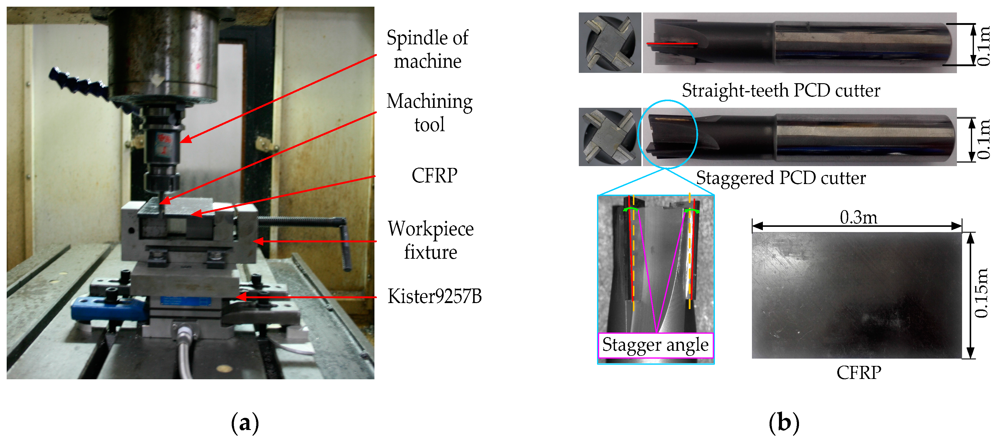
In order to study the wear mechanism of staggered PCD cutters and the effect of tool wear on the machining surface quality of CFRP, a side milling test of CFRP was designed in this paper. The test was conducted on the three-axis milling machine VDL-1000E, Direct CNC, Dinnington, UK, CRFP T700 was selected as the workpiece material, it was 3.5 mm thick, and its main performance and structural parameters are shown in Table 1 and Table 2, respectively. The test system is shown in Figure 1, in which the cutting edge of the staggered PCD cutter had an inclination angle of 5°, while the inclination angle of its adjacent cutting edge was in the opposite direction, and staggered along the circumferential direction of the tool.
In terms of the milling parameters, the milling speed was 150 m/min, the feed per tooth was 0.02 mm/z, and the cutting width was 1 mm. The staggered and straight-teeth PCD cutters were used sequentially for the cutting test. In order to study the effect of tool wear on machining surface quality, both cutter and workpiece were examined after milling every 3 m until obvious burr defects appeared in the machining surface, so that the wear topography and surface quality could be detected. The tool wear and burr defects were detected by the extended depth of field microscope VHX-1000 and scanning electron microscope, while the surface morphology of CFRP was measured by white-light interferometer TalySurf CCI, Taylor Hobson, Leicester, UK, and scanning electron microscope FEI Sirion 200.
3. Results and Discussion
3.1. Tool Wear
Figure 2 shows the tool wear topography of milling 84-meter CFRP with a staggered PCD cutter. It can be seen from Figure 2 that the wear of the staggered PCD cutter was mainly concentrated on the cutting edge, its main form was blunt wear, and rake and flank wear were not obvious. Nonetheless, the cutting-edge wear of the staggered PCD cutter was obviously uneven in an approximately circular arc. That is, it was relatively small in the contact zone with the upper and lower surfaces of the workpiece, while it was larger in the contact area with the middle of the workpiece. For an accurate measurement of the worn cutting-edge radius, the extended depth of field microscope was used to obtain the cross-section contour of the cutting edge, which is shown in Figure 3. In order to study the variation law of the cutting-edge wear due to various milling lengths, the maximum cutting-edge radius Rmax was introduced to characterize the edge wear.
Figure 4 shows the variation law of the maximum cutting-edge radius Rmax due to variations in milling length L, in which the initial cutting-edge radius was 20 µm. The tool wore rapidly with an increase of milling length; the cutting-edge material was removed and the sharp cutting edge became obtuse-circular, which resulted in the increase in the cutting-edge radius. The Rmax reached 57 µm when the milling length was 21m. Afterwards, the tool wear began to slow down, thus the Rmax fell into 57–70 µm, and its increase was not clear. However, when the milling length was more than 72 m, the Rmax increased more, reaching 76 µm when the milling length was 81 m. Nonetheless, the cutting-edge topography was still good, and defects such as obvious tipping and grooves did not occur. Through further EDS analysis of the wear area, obvious signs of adhesive, oxidation or diffusion wear were not found. It was concluded from the wear zone topography and wear curve characteristics that the main wear mechanism of the staggered PCD cutter is abrasive wear.
3.2. Effects of Tool Wear on Milling Force
Figure 5 shows the cutting force curves of the staggered PCD cutter under wear conditions. It can be seen that all the milling forces in three directions increased with increasing milling length. Among them, the main milling force increased most obviously, while the axial force varied the least. This is because the increase of cutting edge wear radius caused a decrease in the rake angle, resulting in aggravation of cutting deformation, and thus the main cutting force increased significantly. However, the cutting-edge wear worsened the extrusion and ploughing of the workpiece, which resulted in a minor increase in the axial force and radial force. The milling force curves can obviously be divided into three stages, corresponding to the tool wear state. In the first stage, when the milling length was less than 21 m, the cutting-edge radius Rmax increased quickly with the increase in milling length, and the milling force increased obviously. In the second stage, when the milling length ranged from 21 to 72 m, the Rmax increased slowly, and the milling force in each direction changed gently. Moreover, when the milling length was over 51 m, the main milling force increased more obviously than the other two forces, and burrs began to appear on the workpiece surface, and their length and density increased with the intension of tool wear. In the third stage, when the milling length ranged from 72 to 100 m, the cutting edge became obviously blunt, a large number of burrs were generated on both upper and lower surfaces of the workpiece, and the milling force in each direction increased obviously.
3.3. Effects of Tool Wear on Machining Surface Topography
The anisotropy of CFRP makes it easy to cause problems after machining, such as fiber fracture, fiber exposure or fall off, fiber pulling out from the matrix, debonding and delamination etc. Figure 6 shows the surface topography of the workpiece machined by the staggered PCD cutter under various wear conditions.
It can be seen from Figure 6a that, when the milling length was 3 m, there was no obvious wear on the cutting edge, the machining surface was relatively smooth in the fiber layer region of 45° and 135°, a tiny groove appeared in the fiber layer region of 0°, and a few fiber bundles protruded from the fiber layer region of 90°. A corresponding 2D contour of the surface topography was further extracted, shown in Figure 6c. The fact that the overall contour curve fluctuated within ±2 µm indicated that the machining surface quality was relatively satisfactory. It can be learned from Figure 6b that, when the milling length was 51 m, the cutting-edge radius reached 61µm and the machining surface was still relatively smooth in the fiber layer region of 45° and 135°, while the local fiber bundles protruded and pulled apart in the fiber layer region of 0°, and fiber bundles were pulled out so seriously as to cause hole defects in the fiber layer region of 90°. Its 2D contour was extracted, as shown in Figure 6d, from which it can be seen that the hole depth was up to 52 µm, and that the machining surface quality deteriorated gradually.
In order to further analyze the effects of tool wear on machining surface quality, SEM was used to test the machining surface. Figure 7 displays the SEM topography of the machining surface in various wear states. It can be learned from analysis that the fiber fracture topographies with obvious differences and the area coated with resin appeared on the machining surface with the extension of cutting edge wear zone. As shown in Figure 7a, when the cutting-edge radius was 23 µm, the cutting edge was relatively sharp, residual resin was not found and the fiber fracture was even on the machining surface, and the machining surface topography was better. It can be seen from Figure 7b that, when the cutting-edge radius Rmax increased to 61 µm, the CFRP breakage form tended towards fiber bundle extrusion, some fiber particles did not fall off, and the fiber fracture became gradually irregular. In addition, the milling temperature increment heated and softened the resin materials, and to some extent the machining surface was coated with resin under the ironing effect of the cutting tool. The machining surface was composed of irregular fiber fracture and partial resin backfill, and thus the surface quality dropped obviously. Figure 7c shows that when the cutting-edge radius further increased to 76 µm, the expansion of fiber bundle extrusion and resin backfill resulted in adhesive fiber particles being coated with resin. Thus, the fiber bundles were pulled out or fell off from the matrix for the effect of strong scraping, and such defects as fiber fracture exposure, groove and hole, etc., appeared clearly.
3.4. Burr Formation on the Workpiece Surface
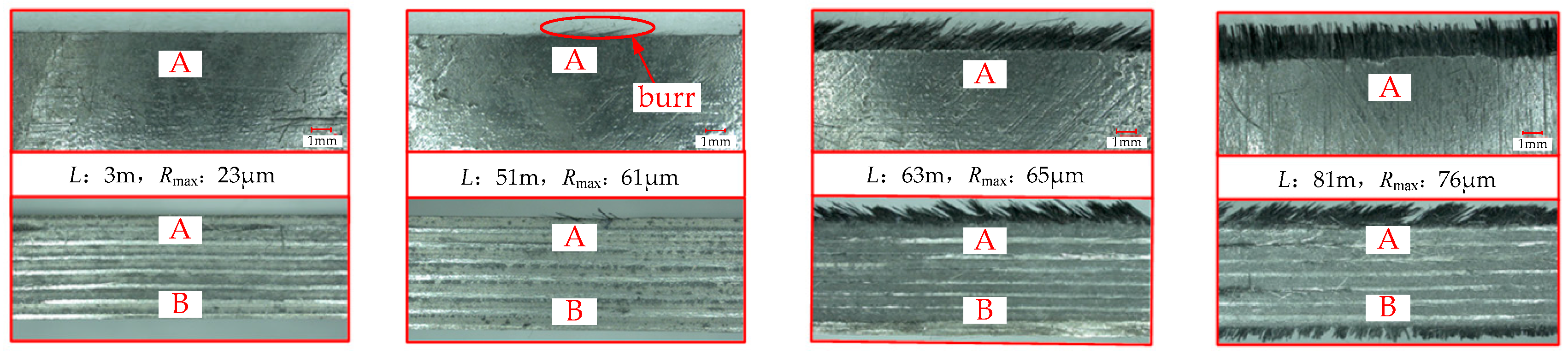
Figure 8 shows burr formation on the machined workpiece surface when milling CFRP with the staggered PCD cutter. In the initial stage of tool wear, the machining surface quality was better, and no obvious burrs were found. With the increase in milling length, only minimal shorter burrs appeared on the upper edge of workpiece surface when the cutting-edge radius reached 61 µm. Afterwards, with the accumulation of cutting edge wear, the section of the cutting edge in contact with the upper edge of the workpiece surface became obviously blunt; thus, even inclination-angle cutting could not effectively cut off the burrs on the workpiece surface edge. Moreover, the length and density of burrs increased gradually. When the cutting-edge radius reached 76 µm, a large range of burrs appeared on the upper and lower surfaces of the machined workpiece, and almost covering the entire edges of the upper and lower surfaces.
4. Comparison of Cutting Performance between Two Different PCD Cutters
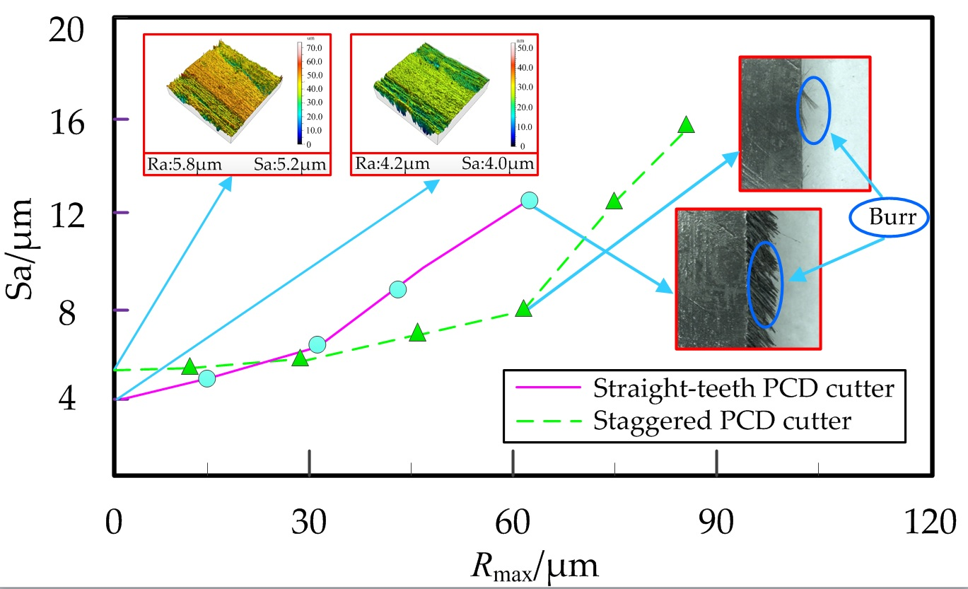
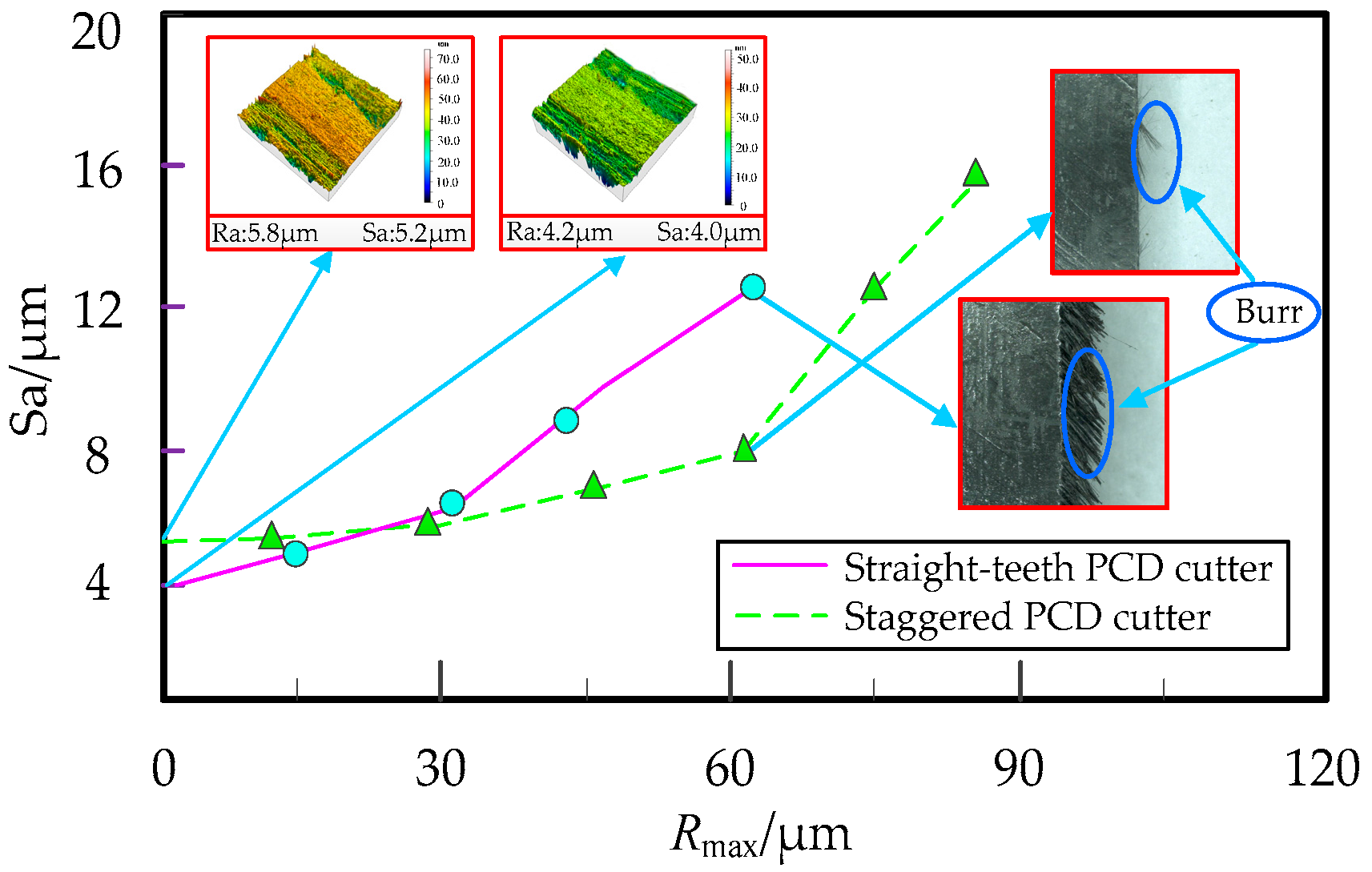
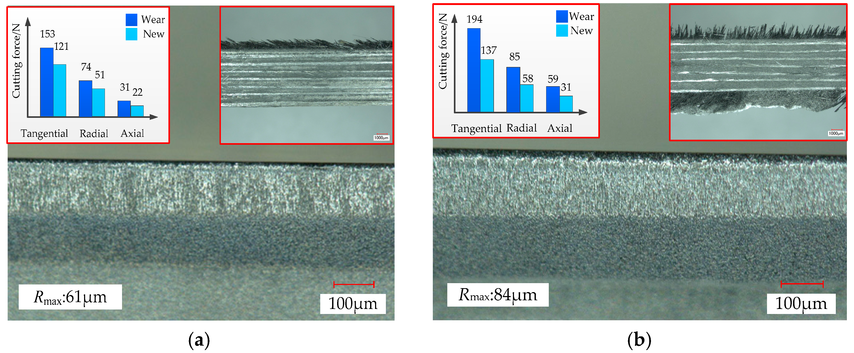
Figure 9 shows the comparison of machining surface quality between the staggered PCD cutter and the straight-teeth PCD cutter in milling CFRP. It can be learned from Figure 9 that in the state of no tool wear, compared with the staggered PCD cutter, the straight-teeth PCD cutter produced better machining surface roughness, and the surface topography was more regular and smoother. With an increase of the cutting-edge radius, the surface roughness Sa of the staggered PCD cutter varied slightly, while the Sa of the straight-teeth PCD cutter increased significantly. When the cutting-edge radius reached 38 µm, the surface roughness of the straight-teeth PCD cutter exceeded that of the staggered PCD cutter, and with the accumulation of cutting edge wear, the gap of surface roughness between the two PCD cutters widened increasingly. When the cutting-edge radius reached 61 µm, a certain number of burrs appeared on the machining surface of the straight-teeth PCD cutter. However, in the same wear condition, only a few burrs occurred on that of the staggered PCD cutter; the reason for this is that the cutting edge of the staggered PCD cutter has an alternate sinistral-dextral inclination angle structure. Thus, in the machining process, both the upper and lower surfaces of the workpiece can bear alternately sinistral-downward and dextral-upward cutting forces, which puts a more even and stable stress on the fiber layer. In addition, in the inclination-angle cutting condition, the fiber layer on the upper and lower surfaces of the workpiece is more likely to be cut off, so that the burrs on both of the surfaces can be effectively suppressed.
Figure 10 shows the comparison of the wear morphologies between the two PCD cutters after milling CFRP 60 m long. It can be learned from Figure 10 that the cutting-edge wear degree of the staggered PCD cutter was obviously smaller than that of the straight-teeth PCD cutter. By comparison of cutting forces without the tool wear, the main cutting force of the staggered PCD cutter increased by 26.4%, while that of the straight-teeth PCD cutter increased by 41.6%. Moreover, for the staggered PCD cutter, burrs were mainly concentrated on the upper machining surface, while for the straight-teeth PCD cutter, a large number of burrs existed on both the upper and lower machining surfaces. This is because, in the cutting process with the staggered PCD cutter, the effect of the inclination angle and axial rake angle increased the contact edge length of the cutter and workpiece, and thus the load on the unit cutting edge decreased so that the cutting got brisker. Meanwhile, compared with the linear contact of the straight-teeth PCD cutter, the staggered PCD cutter formed point contact, which resulted in the periodical variation of the edge length during cutting in and out. The cutting edge of the staggered PCD cutter was involved in cutting alternately, so that the instantaneous resistance decreased obviously and the cutting was more stable, and thus the rate of tool wear slowed down.
5. Conclusions
- The wear zone of the staggered PCD cutter is mainly concentrated on the cutting edge, so the cutting-edge wear radius is introduced to characterize tool wear. With the increase of the cutting length, both the cutting-edge radius and the milling force increase gradually as effect of the abrasive wear mechanism. Nonetheless, the main cutting force increases most obviously, while the axial force varies relatively little.
- There are obvious differences in the machining surface topography in all fiber layer regions. Fiber bundles pulling out and forming hole defects first occurs in the fiber layer region of 90°, tiny grooves mostly appear in the fiber layer region of 0°, and the machining surfaces in the fiber layer regions of 45° and 135° are smoother. In addition, with an increase of milling length, the surface topography in all fiber layer regions gradually gets more complex.
- The types of surface defect change obviously as the tool wear proceeds. When the wear degree of the cutting edge is small, the fiber fracture of the surface machined with the staggered PCD cutter is relatively flat. With the intension of the cutting-edge wear, the fiber fracture topography becomes irregular, the resin coating and backfill occur locally, and defects such as fiber bundle exposure, and grooves and holes appear; thus, the surface topography deteriorates gradually.
- Compared with the straight-teeth PCD cutter, the cutting edge of the staggered PCD milling cutter can form a sinistral-dextral inclination angle structure, which can make the workpiece bear two-way forces, inhibit delamination defects, and improve the cutting conditions, while the inclined cutting edge can increase the contact area between the tool and the workpiece, reduce the load on the unit cutting edge, and prolong the tool life. Thus, the staggered PCD cutter shows better cutting performance, and its wear resistance and machining quality have improved significantly.
Acknowledgments
The authors would like to acknowledge the support of the International S&T Cooperation Program of China (Grant No. 2014DFA70400), the National Natural Science Foundation of China (Grant No. 51475125), the Natural Science Foundation of Heilongjiang Province (Grant No. E2016047), the Program for Harbin Science and Technology Innovation Talents (Grant No. 2015RQQXJ039), and the Distinguished Young Talents Program of Harbin University of Science and Technology.
Author Contributions
Tao Chen and Daoyuan Wang designed the tool and experiment. Tao Chen, Daoyuan Wang and Fei Gao performed the experiment. Tao Chen, Daoyuan Wang, Fei Gao and Xianli Liu analyzed the data. Tao Chen and Daoyuan Wang wrote the paper.
Conflicts of Interest
The authors declare no conflict of interest.
References
- Liu, J.; Chen, G.; Ji, C.; Qin, X.; Li, H.; Ren, C. An investigation of workpiece temperature variation of helical milling for carbon fiber reinforced plastics(CFRP). Int. J. Mach. Tool Manu. 2014, 86, 89–103. [Google Scholar] [CrossRef]
- Maegawa, S.; Hayakawa, S.; Itoigawa, F.; Nakamura, T. Development of novel tool for cutting of carbon-fiber-reinforced plastics (Positive use of abrasive wear at tool edge for reduction in cutting force). J. Mech. Eng. 2015, 2, 1–13. [Google Scholar] [CrossRef]
- EI-Hofy, M.H.; Soo, S.L.; Aspinwall, D.K.; Simb, W.M.; Pearsonc, D.; Hardend, P. Factors Affecting Workpiece Surface Integrity in Slotting of CFRP. Proc. Eng. 2011, 19, 94–99. [Google Scholar] [CrossRef]
- Hintze, W.; Hartmann, D.; Schütte, C. Occurrence and propagation of delamination during the machining of carbon fibre reinforced plastics (CFRPs)—An experimental study. Compos. Sci. Technol. 2011, 71, 1719–1726. [Google Scholar] [CrossRef]
- Karpat, Y.; Bahtiyar, O.; Değer, B. Mechanistic force modeling for milling of unidirectional carbon fiber reinforced polymer laminates. Int. J. Mach. Tool Manu. 2012, 56, 79–93. [Google Scholar] [CrossRef]
- Khairusshima, M.K.N.; Hassan, C.H.C.; Jaharah, A.G.; Amin, A.K.M.; Idriss, A.N.M. Effect of chilled air on tool wear and workpiece quality during milling of carbon fibre-reinforced plastic. Wear 2013, 302, 1113–1123. [Google Scholar] [CrossRef]
- Colak, O.; Sunar, T. Cutting Forces and 3D Surface Analysis of CFRP Milling with PCD Cutting Tools. Proc. Cirp. 2016, 45, 75–78. [Google Scholar] [CrossRef]
- Gao, C.; Xiao, J.; Xu, J.; Ke, Y. Factor analysis of machining parameters of fiber-reinforced polymer composites based on finite element simulation with experimental investigation. Int. J. Adv. Manuf. Technol. 2016, 83, 1113–1125. [Google Scholar] [CrossRef]
- Chibane, H.; Morandeau, A.; Serra, R.; Bouchou, A.; Leroy, R. Optimal milling conditions for carbon/epoxy composite material using damage and vibration analysis. Int. J. Adv. Manuf. Technol. 2013, 68, 1111–1121. [Google Scholar] [CrossRef]
- Haddad, M.; Zitoune, R.; Eyma, F.; Castanié, B. Machinability and surface quality during high speed trimming of multi directional CFRP. Int. J. Mach. Machinab. Mater. 2013, 13, 289–310. [Google Scholar] [CrossRef]
- Haddad, M.; Zitoune, R.; Eyma, F. Influence of Machining Process and Machining Induced Surface Roughness on Mechanical Properties of Continuous Fiber Composites. Exp. Mech. 2014, 55, 1–10. [Google Scholar] [CrossRef]
- Davim, J.P.; Mata, F.; Gaitonde, V.N.; Karnik, S.R. Machinability Evaluation in Unreinforced and Reinforced PEEK Composotes using Response Surface Models. J. Thermoplast. Compos. Mater. 2010, 23, 5–18. [Google Scholar] [CrossRef]
- Davim, J.P.; Reis, P. Machinability study on composite (polyetheretherketone reinforced with 30% glass fibre-PEEK GF 30) using polycrystalline diamond (PCD) and cemented carbide (K20) tools. Int. J. Adv. Manuf. Technol. 2004, 23, 412–418. [Google Scholar] [CrossRef]
- Davim, J.P.; Mata, F. Optimization of surface roughness on turning fiber reinforced plastics (FRP’s) with diamond cutting tools. Int. J. Adv. Manuf. Technol. 2005, 26, 319–323. [Google Scholar] [CrossRef]
- Davim, J.P.; Silva, L.R.; Festas, A.; Abrão, A.M. Machinability study on precision turning of PA66 polyamide with and without glass fiber reinforcing. Mater. Des. 2009, 30, 228–234. [Google Scholar] [CrossRef]
- Davim, J.P.; Mata, F. Physical cutting model of PEEK composites. Mater. Des. 2006, 27, 847–852. [Google Scholar] [CrossRef]
- Schornik, V.; Dana, M.; Zetková, I. The Influence of the Cutting Conditions on the Machined Surface Quality when the CFRP is Machined. Proc. Eng. 2015, 100, 1270–1276. [Google Scholar] [CrossRef]
- Voß, R.; Henerichs, M.; Rupp, S.; Kuster, F.; Wegener, K. Evaluation of bore exit quality for fibre reinforced plastics including delamination and uncut fibres. CIRP J. Manuf. Sci. Technol. 2016, 12, 56–66. [Google Scholar] [CrossRef]
- Davim, J.P. Machinability of Fibre-Reinforced Plastics; DE Gruyter: Berlin, Germany, 2015; ISBN 978-3-11-029222-0. [Google Scholar]
- Davim, J.P. Machining of Composite Materials; ISTE-Wiley: London, UK, 2009; ISBN 978-1-84821-103-4. [Google Scholar]
- Kilickap, E.; Yardimeden, A.; Celik, Y.H. Investigation of experimental study of end milling of CFRP composite. Sci. Eng. Compos. Mater. 2013, 22, 89–95. [Google Scholar] [CrossRef]
- Muhamad Khairussaleh, N.K.; Haron, C.H.C.; Ghani, J.A. Study on wear mechanism of solid carbide cutting tool in milling CFRP. J. Mater. Res. 2016, 1, 1–7. [Google Scholar] [CrossRef]
- Yang, X.F.; Yang, G.H.; Li, Y.S.; Liu, J.D.; Xu, Z.L. A new type of cross-edged carbide end milling cutter with carbon fiber research on composite materials. Rare Metals Cemented Carbides 2015, 43, 67–71. (In Chinese) [Google Scholar]
Figure 1.
Test system: (a) test layout; (b) cutting tool and workpiece.

Figure 2.
Flank wear topography of staggered PCD cutter after milling 84 m.
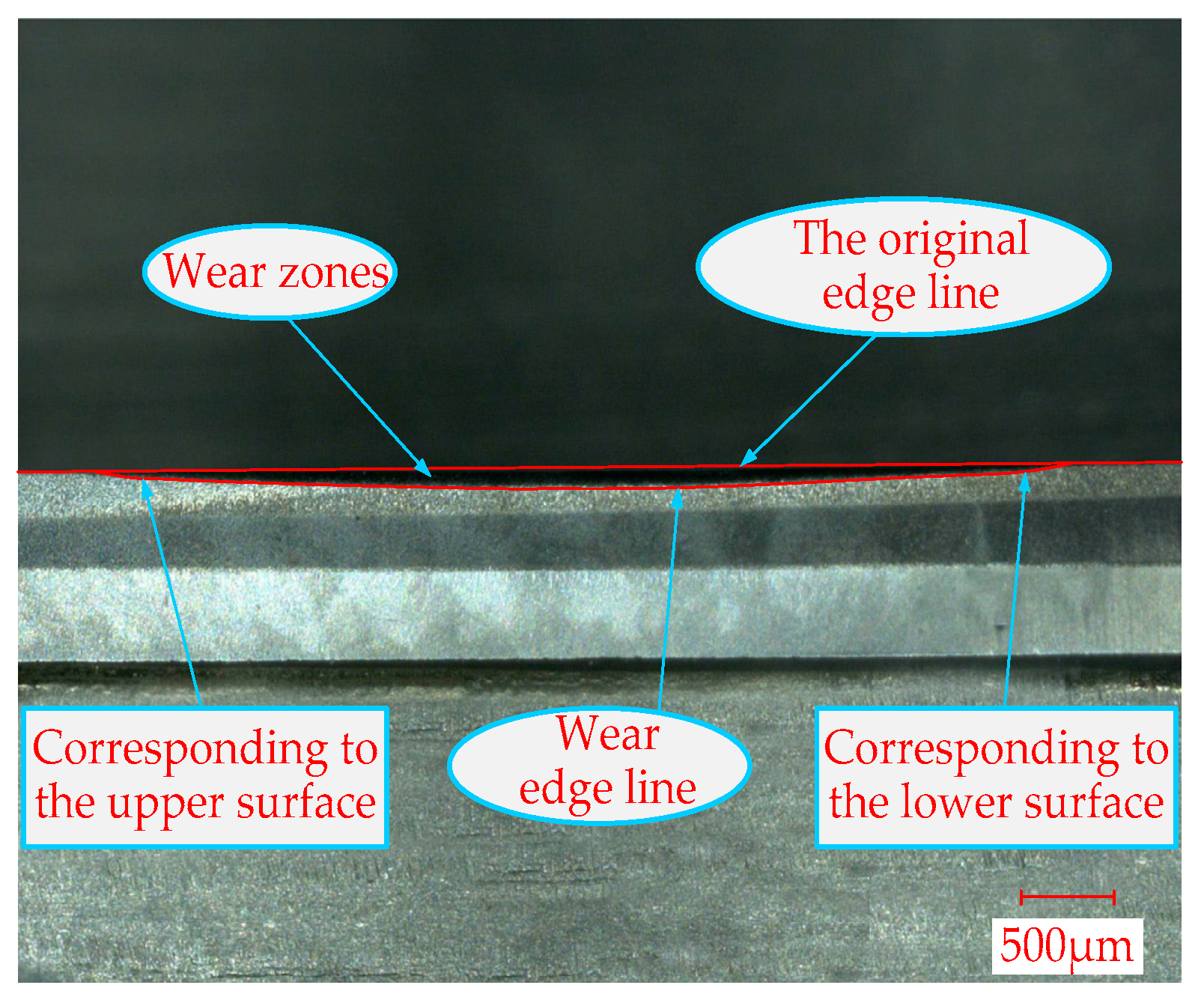
Figure 3.
Measurement of cutting edge radius Rmax.
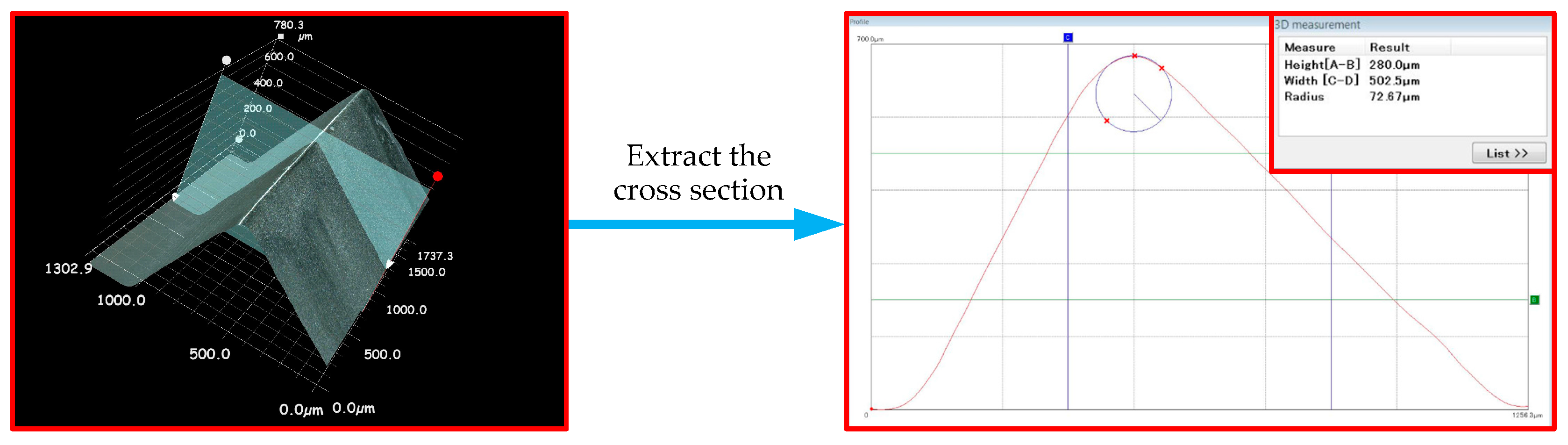
Figure 4.
Tool wear law and mechanism: (a) Variation law of Rmax due to various milling length; (b) EDS analysis of the wear area, when the milling length is 81m.
Figure 4.
Tool wear law and mechanism: (a) Variation law of Rmax due to various milling length; (b) EDS analysis of the wear area, when the milling length is 81m.

Figure 5.
The milling force curves of staggered PCD cutter due to variations in milling length.
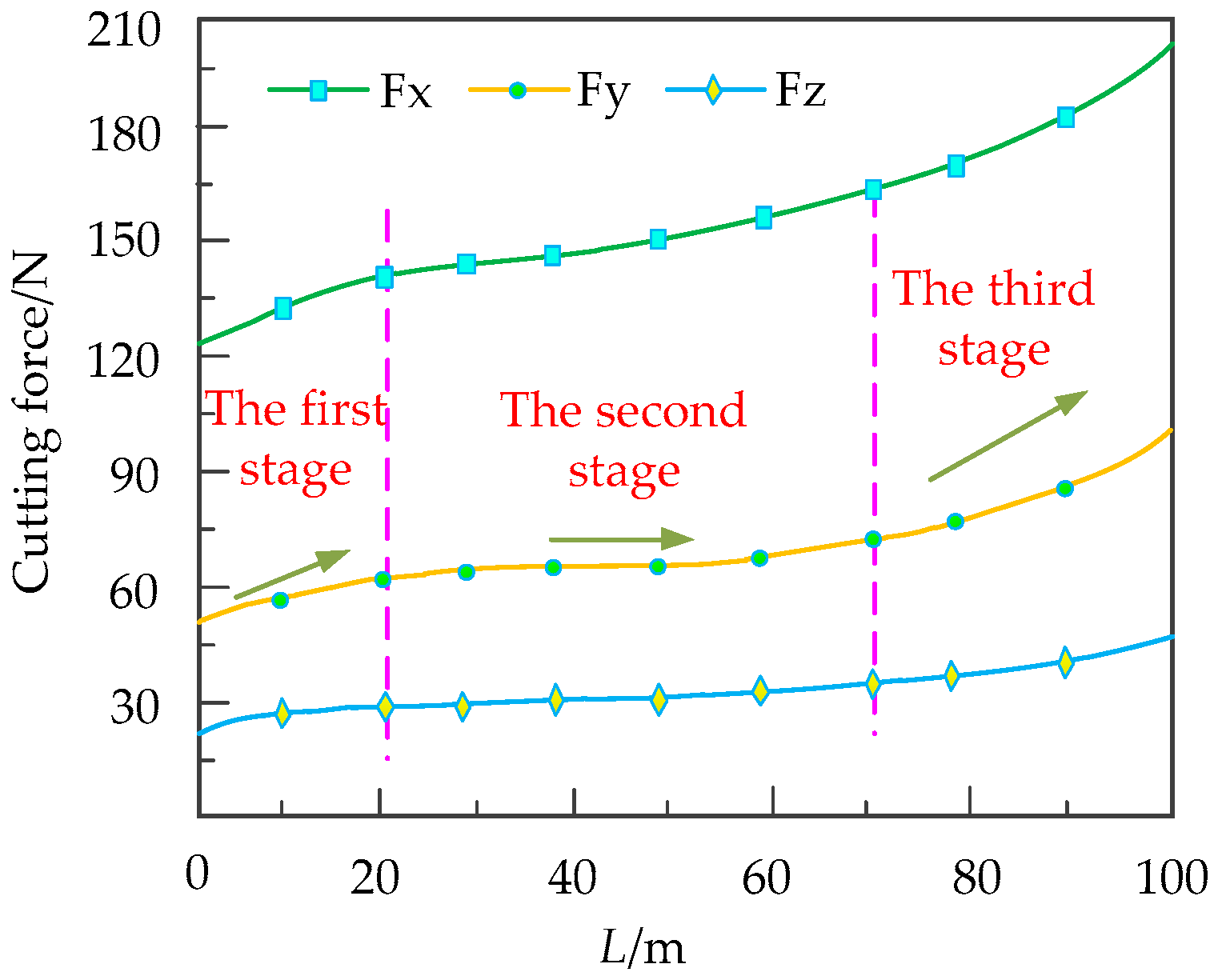
Figure 6.
The surface topography of CFRP under various wear conditions: (a) 3D machining surface topography (L: 3 m, Rmax: 23 µm); (b) 3D machining surface topography (L: 51 m, Rmax: 61 µm); (c) 2D contour (L: 3 m, Rmax: 23 µm); (d) 2D contour (L: 51 m, Rmax: 61 µm).
Figure 6.
The surface topography of CFRP under various wear conditions: (a) 3D machining surface topography (L: 3 m, Rmax: 23 µm); (b) 3D machining surface topography (L: 51 m, Rmax: 61 µm); (c) 2D contour (L: 3 m, Rmax: 23 µm); (d) 2D contour (L: 51 m, Rmax: 61 µm).
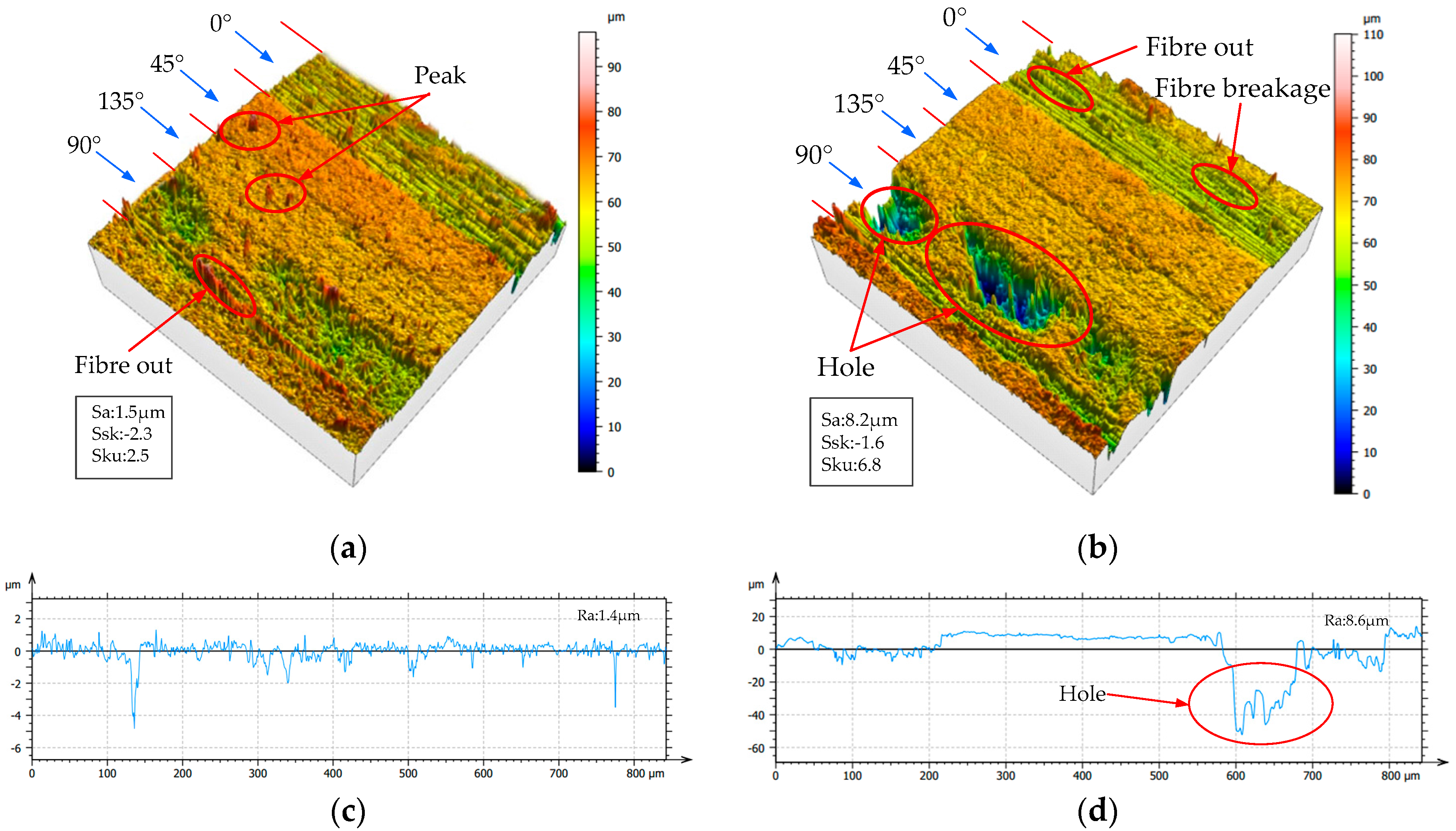
Figure 7.
Surface SEM image of CFRP in various wear states: (a) L: 3 m, Rmax: 23 µm; (b) L: 51 m, Rmax: 61 µm; (c) L: 81 m, Rmax: 76 µm.
Figure 7.
Surface SEM image of CFRP in various wear states: (a) L: 3 m, Rmax: 23 µm; (b) L: 51 m, Rmax: 61 µm; (c) L: 81 m, Rmax: 76 µm.

Figure 8.
Burr formation on the machined workpiece surface: A-upper surface B-lower surface.

Figure 9.
Comparison of the surface quality between the two PCD cutters.

Figure 10.
Comparison of the wear morphologies between the two PCD cutters: (a) staggered PCD cutter; (b) straight-teeth PCD cutter.
Figure 10.
Comparison of the wear morphologies between the two PCD cutters: (a) staggered PCD cutter; (b) straight-teeth PCD cutter.


Table 1.
The performance parameters of T700 carbon fiber.
| Filament Diameter | Filament Radius | Longitudinal Young Modulus | Transversal Young Modulus | Shear Modulus | Elongation | Density |
|---|---|---|---|---|---|---|
| 12000 | 7 µm | 142 GPa | 8.4 GPa | 3.8 GPa | 2.11% | 1.8 g/cm3 |
Table 2.
The structural parameters of carbon fiber reinforced plastic (CFRP).
| Ply Sequences | Carbon Fiber Volume Fraction | Reinforcing Material | Matrix Material | Specification (mm) |
|---|---|---|---|---|
| 0°/45°/135°/90° | 60 ± 5% | T700 | AG-80 epoxy resin | 300 × 150 × 3.5 |
© 2017 by the authors. Licensee MDPI, Basel, Switzerland. This article is an open access article distributed under the terms and conditions of the Creative Commons Attribution (CC BY) license (http://creativecommons.org/licenses/by/4.0/).
Share and Cite
MDPI and ACS Style
Chen, T.; Wang, D.; Gao, F.; Liu, X. Experimental Study on Milling CFRP with Staggered PCD Cutter. Appl. Sci. 2017, 7, 934. https://doi.org/10.3390/app7090934
AMA Style
Chen T, Wang D, Gao F, Liu X. Experimental Study on Milling CFRP with Staggered PCD Cutter. Applied Sciences. 2017; 7(9):934. https://doi.org/10.3390/app7090934
Chicago/Turabian StyleChen, Tao, Daoyuan Wang, Fei Gao, and Xianli Liu. 2017. "Experimental Study on Milling CFRP with Staggered PCD Cutter" Applied Sciences 7, no. 9: 934. https://doi.org/10.3390/app7090934
Note that from the first issue of 2016, this journal uses article numbers instead of page numbers. See further details here.