
Functionalization of a Hydrophilic Commercial Membrane Using Inorganic-Organic Polymers Coatings for Membrane Distillation

 , ,
, ,
Abstract
:1. Introduction
2. Materials and Methods
2.1. Membranes
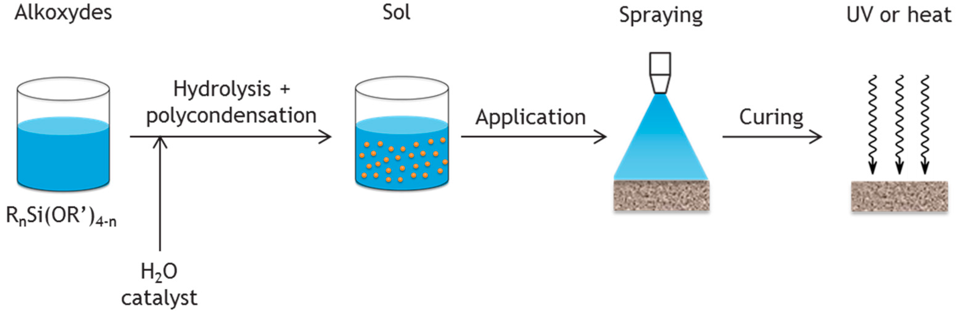
2.2. Coatings
2.3. Characterization Methods
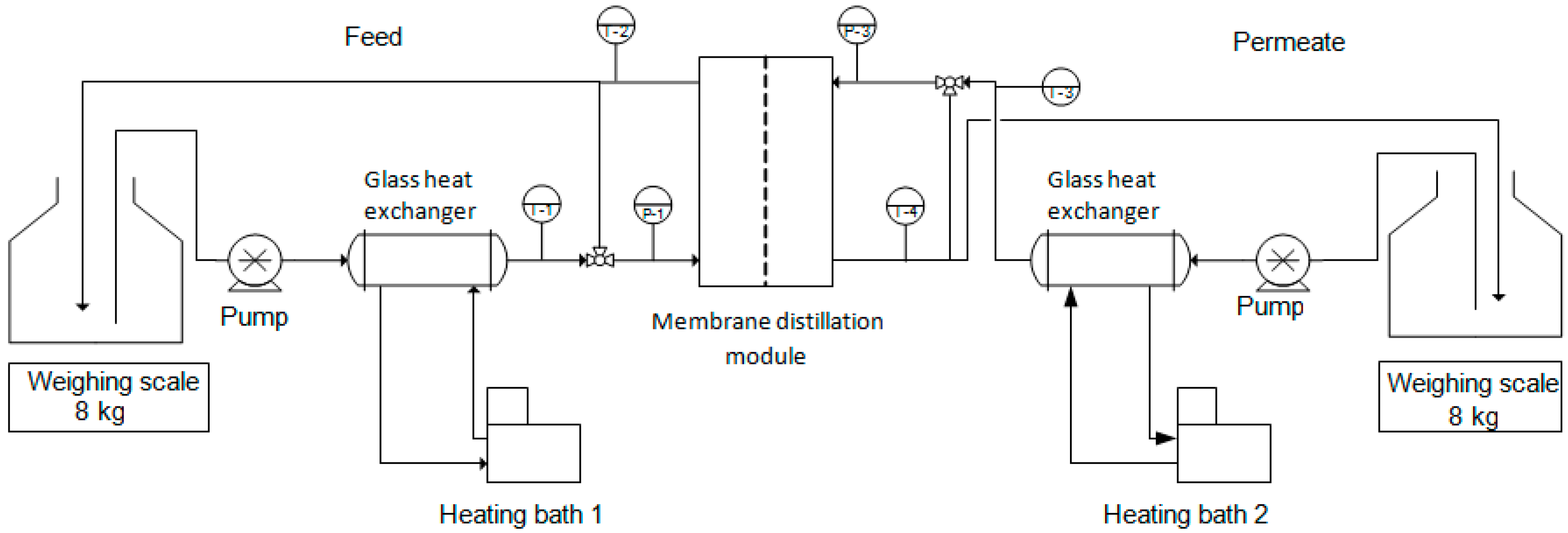
2.4. Membrane Distillation Setup
3. Results
3.1. Characterization of the Membranes
3.2. Wetting Resistance of the Coating
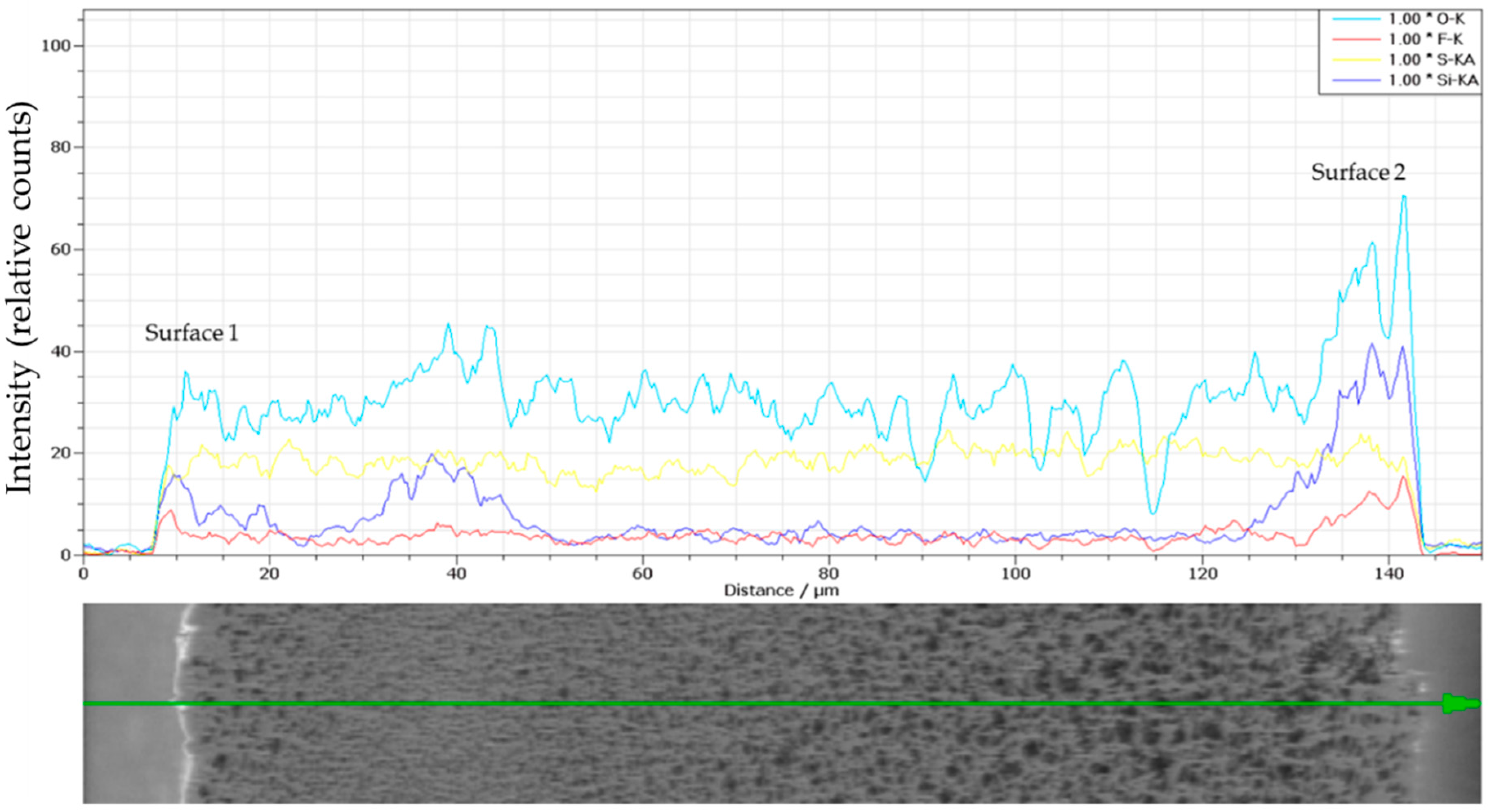
3.3. Structure of the Coating
3.4. Membrane Distillation Performance
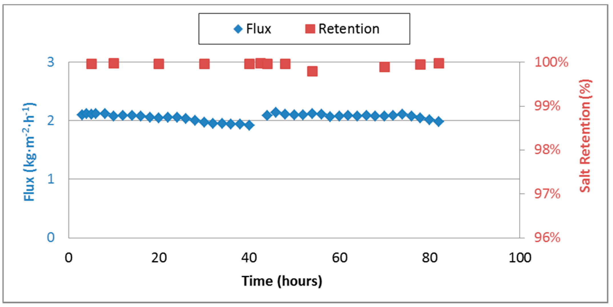
3.5. Medium Term Performance
4. Conclusions
Acknowledgments
Author Contributions
Conflicts of Interest
References
- Zhang, P.; Knötig, P.; Gray, S.; Duke, M. Scale reduction and cleaning techniques during direct contact membrane distillation of seawater reverse osmosis brine. Desalination 2015, 374, 20–30. [Google Scholar] [CrossRef]
- Kesieme, U.K. Mine Waste Water Treatment and Acid Recovery Using Membrane Distillation and Solvent Extraction. Ph.D. Thesis, Victoria University, Footscray, Australia, 2015. [Google Scholar]
- Calabrò, V.; Drioli, E.; Matera, F. Membrane distillation in the textile wastewater treatment. Desalination 1991, 83, 209–224. [Google Scholar] [CrossRef]
- Hickenbottom, K.L.; Cath, T.Y. Sustainable operation of membrane distillation for enhancement of mineral recovery from hypersaline solutions. J. Membr. Sci. 2014, 454, 426–435. [Google Scholar] [CrossRef]
- Christensen, K.; Andresen, R.; Tandskov, I.; Norddahl, B.; du Preez, J.H. Using direct contact membrane distillation for whey protein concentration. Desalination 2006, 200, 523–525. [Google Scholar] [CrossRef]
- Tomaszewska, M.; Gryta, M.; Morawski, A.W. Study on the concentration of acids by membrane distillation. J. Membr. Sci. 1995, 102, 113–122. [Google Scholar] [CrossRef]
- Teoh, M.M.; Chung, T.S. Membrane distillation with hydrophobic macrovoid-free PVDF-PTFE hollow fiber membranes. Sep. Purif. Technol. 2009, 66, 229–236. [Google Scholar] [CrossRef]
- Bonyadi, S.; Chung, T.S. Flux enhancement in membrane distillation by fabrication of dual layer hydrophilic-hydrophobic hollow fiber membranes. J. Membr. Sci. 2007, 306, 134–146. [Google Scholar] [CrossRef]
- El-Bourawi, M.S.; Ding, Z.; Ma, R.; Khayet, M. A framework for better understanding membrane distillation separation process. J. Membr. Sci. 2006, 285, 4–29. [Google Scholar] [CrossRef]
- Alkhudhiri, A.; Darwish, N.; Hilal, N. Membrane distillation: A comprehensive review. Desalination 2012, 287, 2–18. [Google Scholar] [CrossRef]
- Lawson, K.W.; Lloyd, D.R. Membrane distillation. J. Membr. Sci. 1997, 124, 1–25. [Google Scholar] [CrossRef]
- Schneider, K.; Hölz, W.; Wollbeck, R.; Ripperger, S. Membranes and modules for transmembrane distillation. J. Membr. Sci. 1988, 39, 25–42. [Google Scholar] [CrossRef]
- Khayet, M.; Matsuura, T. Membrane Distillation: Principles and Applications; Elsevier B.V.: Amsterdam, The Netherland, 2011. [Google Scholar]
- Eykens, L.; De Sitter, K.; Dotremont, C.; Pinoy, L.; van der Bruggen, B. How to Optimize the Membrane Properties for Membrane Distillation: A Review. Ind. Eng. Chem. Res. 2016, 55, 9333–9343. [Google Scholar] [CrossRef]
- Alklaibi, A.M.; Lior, N. Transport analysis of air-gap membrane distillation. J. Membr. Sci. 2005, 255, 239–253. [Google Scholar] [CrossRef]
- Abu Al-Rub, F.A.; Banat, F.; Beni-Melhim, K. Parametric Sensitivity Analysis of Direct Contact Membrane Distillation. Sep. Sci. Technol. 2002, 37, 3245–3271. [Google Scholar] [CrossRef]
- Jönsson, A.S.; Wimmerstedt, R.; Harrysson, A.C. Membrane distillation—A theoretical study of evaporation through microporous membranes. Desalination 1985, 56, 237–249. [Google Scholar] [CrossRef]
- Ali, M.I.; Summers, E.K.; Arafat, H.A.; Lienhard, J.H.V. Effects of membrane properties on water production cost in small scale membrane distillation systems. Desalination 2012, 306, 60–71. [Google Scholar] [CrossRef]
- Bahmanyar, A.; Asghari, M.; Khoobi, N. Numerical simulation and theoretical study on simultaneously effects of operating parameters in direct contact membrane distillation. Chem. Eng. Process. Process Intensif. 2012, 61, 42–50. [Google Scholar] [CrossRef]
- Eykens, L.; Hitsov, I.; de Sitter, K.; Dotremont, C.; Pinoy, L.; Nopens, I.; van der Bruggen, B. Influence of membrane thickness and process conditions on direct contact membrane distillation at different salinities. J. Membr. Sci. 2016, 498, 353–364. [Google Scholar] [CrossRef]
- Thomas, R.; Guillen-Burrieza, E.; Arafat, H.A. Pore structure control of PVDF membranes using a 2-stage coagulation bath phase inversion process for application in membrane distillation (MD). J. Membr. Sci. 2014, 452, 470–480. [Google Scholar] [CrossRef]
- Song, Z.W.; Jiang, L.Y. Optimization of morphology and perf ormance of PVDF hollow fiber for direct contact membrane distillation using experimental design. Chem. Eng. Sci. 2013, 101, 130–143. [Google Scholar] [CrossRef]
- Tang, Y.; Li, N.; Liu, A.; Ding, S.; Yi, C.; Liu, H. Effect of spinning conditions on the structure and performance of hydrophobic PVDF hollow fiber membranes for membrane distillation. Desalination 2012, 287, 326–339. [Google Scholar] [CrossRef]
- García-Payo, M.C.; Essalhi, M.; Khayet, M. Effects of PVDF-HFP concentration on membrane distillation performance and structural morphology of hollow fiber membranes. J. Membr. Sci. 2010, 347, 209–219. [Google Scholar] [CrossRef]
- Kim, Y.; Rana, D.; Matsuura, T.; Chung, W.J. Influence of surface modifying macromolecules on the surface properties of poly(ether sulfone) ultra-filtration membranes. J. Membr. Sci. 2009, 338, 84–91. [Google Scholar] [CrossRef]
- Essalhi, M.; Khayet, M. Surface segregation of fluorinated modifying macromolecule for hydrophobic/hydrophilic membrane preparation and application in air gap and direct contact membrane distillation. J. Membr. Sci. 2012, 417–418, 163–173. [Google Scholar] [CrossRef]
- Khayet, M.; Matsuura, T. Application of surface modifying macromolecules for the preparation of membranes for membrane distillation. Desalination 2003, 158, 51–56. [Google Scholar] [CrossRef]
- Tijing, L.D.; Choi, J.S.; Lee, S.; Kim, S.H.; Shon, H.K. Recent progress of membrane distillation using electrospun nanofibrous membrane. J. Membr. Sci. 2014, 453, 435–462. [Google Scholar] [CrossRef]
- Essalhi, M.; Khayet, M. Self-sustained webs of polyvinylidene fluoride electrospun nanofibers at different electrospinning times: 1. Desalination by direct contact membrane distillation. J. Membr. Sci. 2013, 433, 167–179. [Google Scholar] [CrossRef]
- Tian, M.; Yin, Y.; Yang, C.; Zhao, B.; Song, J.; Liu, J.; Li, X.M.; He, T. CF4 plasma modified highly interconnective porous polysulfone membranes for direct contact membrane distillation (DCMD). Desalination 2015, 369, 105–114. [Google Scholar] [CrossRef]
- Wu, Y.; Kong, Y.; Lin, X.; Liu, W.; Xu, J. Surface-modified hydrophilic membranes in membrane distillation. J. Membr. Sci. 1992, 72, 189–196. [Google Scholar] [CrossRef]
- Razmjou, A.; Arifin, E.; Dong, G.; Mansouri, J.; Chen, V. Superhydrophobic modification of TiO2 nanocomposite PVDF membranes for applications in membrane distillation. J. Membr. Sci. 2012, 415–416, 850–863. [Google Scholar] [CrossRef]
- Khemakhem, S.; Amar, R.B. Modification of Tunisian clay membrane surface by silane grafting: Application for desalination with Air Gap Membrane Distillation process. Colloids Surf. A Physicochem. Eng. Asp. 2011, 387, 79–85. [Google Scholar] [CrossRef]
- Haas, K.-H.; Amberg-Schwab, S.; Rose, K. Functionalized coating materials based on inorganic-organic polymers. Thin Solid Films 1999, 351, 198–203. [Google Scholar] [CrossRef]
- Kron, J.; Amberg-schwab, S.; Schottner, G. Functional coatings on glass using ORMOCER®-systems. Code: BP20. J. Sol-Gel Sci. Technol. 1994, 2, 189–192. [Google Scholar] [CrossRef]
- Matějec, V.; Rose, K.; Hayer, M.; Pospíšllová, M.; Chomát, M. Development of organically modified polysiloxanes for coating optical fibers and their sensitivity to gases and solvents. Sens. Actuators B Chem. 1997, 39, 438–442. [Google Scholar] [CrossRef]
- Liao, Y.; Wang, R.; Tian, M.; Qiu, C.; Fane, A.G. Fabrication of polyvinylidene fluoride (PVDF) nanofiber membranes by electro-spinning for direct contact membrane distillation. J. Membr. Sci. 2013, 425–426, 30–39. [Google Scholar] [CrossRef]
- Khayet, M.; Khulbe, K.C.; Matsuura, T. Characterization of membranes for membrane distillation by atomic force microscopy and estimation of their water vapor transfer coefficients in vacuum membrane distillation process. J. Membr. Sci. 2004, 238, 199–211. [Google Scholar] [CrossRef]
- Hou, D.; Dai, G.; Wang, J.; Fan, H.; Zhang, L.; Luan, Z. Preparation and characterization of PVDF/nonwoven fabric flat-sheet composite membranes for desalination through direct contact membrane distillation. Sep. Purif. Technol. 2012, 101, 1–10. [Google Scholar] [CrossRef]
- Haas, K.H.; Amberg-Schwab, S.; Rose, K.; Schottner, G. Functionalized coatings based on inorganic-organic polymers (ORMOCER S) and their combination with vapor deposited inorganic thin films. Surf. Coat. Technol. 1999, 111, 72–79. [Google Scholar] [CrossRef]
- Schottner, G.; Rose, K.; Posset, U. Scratch and Abrasion Resistant Coatings on Plastic Lenses—State of the Art, Current Developments and Perspectives. J. Sol-Gel Sci. Technol. 2003, 27, 71–79. [Google Scholar] [CrossRef]
- Khayet, M.; Matsuura, T. Preparation and Characterization of Polyvinylidene Fluoride Membranes for Membrane Distillation. Ind. Eng. Chem. Res. 2001, 40, 5710–5718. [Google Scholar] [CrossRef]
- Francis, L.; Ghaffour, N.; Alsaadi, A.S.; Nunes, S.P.; Amy, G.L. Performance evaluation of the DCMD desalination process under bench scale and large scale module operating conditions. J. Membr. Sci. 2014, 455, 103–112. [Google Scholar] [CrossRef]
- Smolders, K.; Franken, A.C.M. Terminology for Membrane Distillation. Desalination 1989, 72, 249–262. [Google Scholar] [CrossRef]
- Khayet, M. Solar desalination by membrane distillation: Dispersion in energy consumption analysis and water production costs (a review). Desalination 2013, 308, 89–101. [Google Scholar] [CrossRef]
- Khare, V.P.; Greenberg, A.R.; Krantz, W.B. Vapor-induced phase separation—Effect of the humid air exposure step on membrane morphology: Part I. Insights from mathematical modeling. J. Membr. Sci. 2005, 258, 140–156. [Google Scholar] [CrossRef]
- Gilron, J.; Ladizansky, Y.; Korin, E. Silica Fouling in Direct Contact Membrane Distillation. Ind. Eng. Chem. Res. 2013, 52, 10521–10529. [Google Scholar] [CrossRef]
- Martínez, L.; Rodríguez-Maroto, J.M. Membrane thickness reduction effects on direct contact membrane distillation performance. J. Membr. Sci. 2008, 312, 143–156. [Google Scholar] [CrossRef]
- Laganà, F.; Barbieri, G.; Drioli, E. Direct contact membrane distillation: Modelling and concentration experiments. J. Membr. Sci. 2000, 166, 1–11. [Google Scholar] [CrossRef]
- Wu, H.Y.; Wang, R.; Field, R.W. Direct contact membrane distillation: An experimental and analytical investigation of the effect of membrane thickness upon transmembrane flux. J. Membr. Sci. 2014, 470, 2257–2265. [Google Scholar] [CrossRef]
- Boubakri, A.; Bouguecha, S.A.-T.; Dhaouadi, I.; Hafiane, A. Effect of operating parameters on boron removal from seawater using membrane distillation process. Desalination 2015, 373, 86–93. [Google Scholar] [CrossRef]

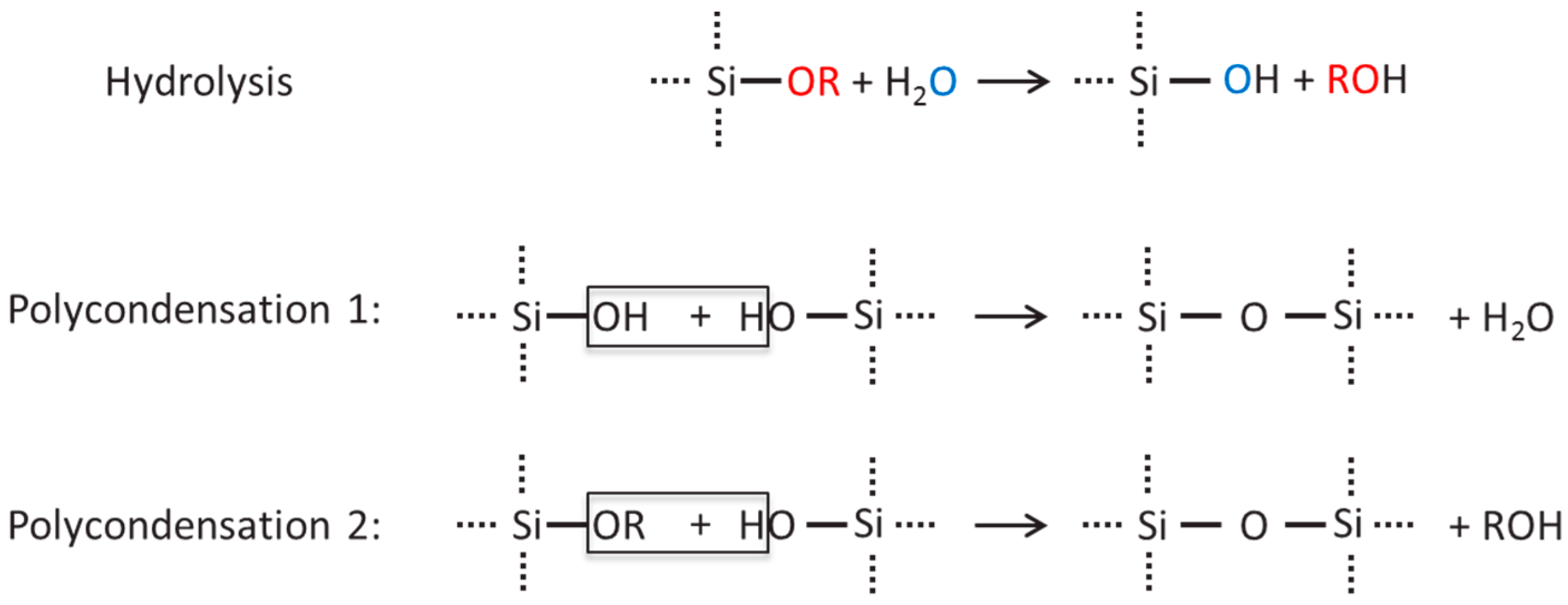
 represents the inorganic network.
 represents the inorganic network,
  represents the organic network formation.
represents the inorganic network, represents the organic network formation.
represents the organic network formation.
represents the inorganic network, represents the organic network formation. represents the inorganic network, represents the organic network formation.
represents the inorganic network, represents the organic network formation.
represents the inorganic network, represents the organic network formation.


| Coating System | Coating Components | Mass Fraction in Coating Solution | Application Method | Network Formation |
|---|---|---|---|---|
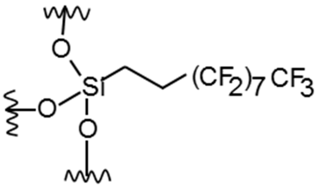
| 1 | PFD solution | 5 wt. % | Roll-to-roll system | No organic crosslinking |
| 2 | PFD solution | 10 wt. % | Roll-to-roll system | No organic crosslinking |
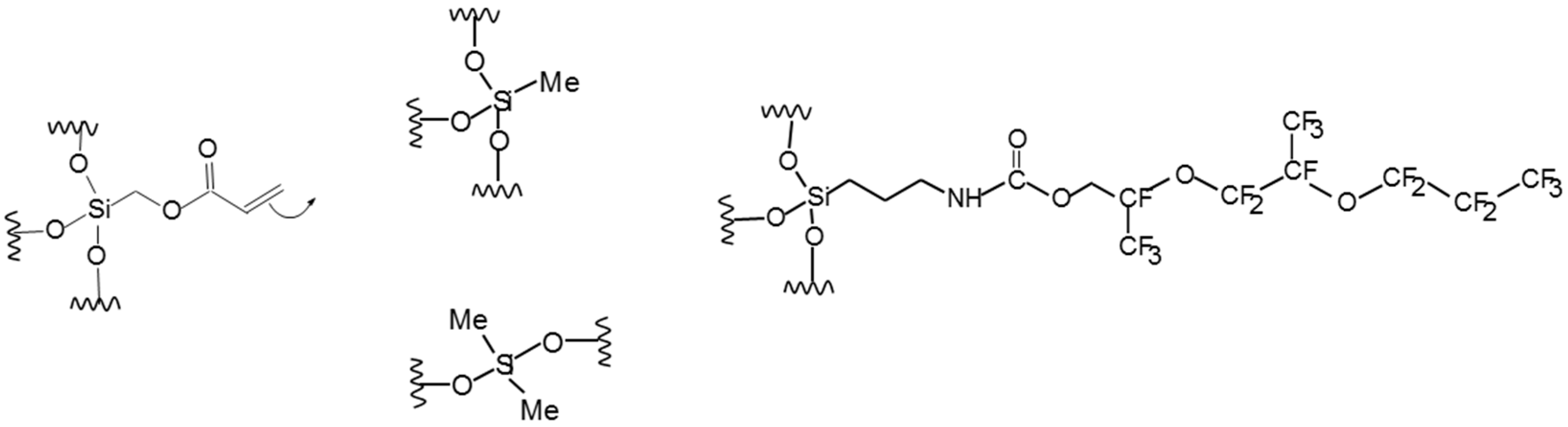
| 3 | Ak/T/D/BTFO2N | 5 wt. % | Bar coater | Acrylic polymerization |
| 4 | Ak/T/D/BTFO2N | 30 wt. % | Roll-to-roll system | Acrylic polymerization |
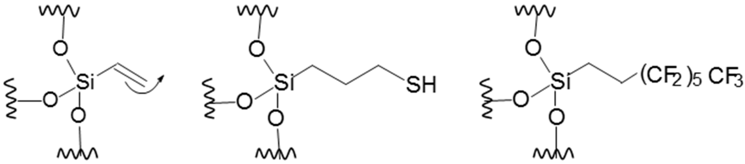
| 5 | V/Mc/F13 | 5 wt. % | Bar coater | Vinyl + SH addition |
| 6 | V/Mc/F13 | 5 wt. % | Spray coater | Vinyl + SH addition |
| 7 | V/Mc/F13 | 5 wt. % | Spray coater | Vinyl + SH addition |
| Membrane | Θ (°) | dmax (µm) | dav (µm) | Δ (μm) | Ε (%) | LEP (bar) |
|---|---|---|---|---|---|---|
| PES (Membrana, MicroPES) | 26 ± 4 | 0.61 ± 0.04 | 0.56 ± 0.03 | 115 ± 1 | 75.2 ± 0.3 | 0 |
| PE (Lydall, Solupor) | 120 ± 1 | 0.32 ± 0.02 | 0.43 ± 0.02 | 99 ± 1 | 75.6 ± 0.6 | 3.9 ± 0.1 |
| PVDF (Millipore, GVHP) | 120 ± 3 | 0.44 ± 0.01 | 0.60 ± 0.01 | 119 ± 1 | 65.7 ± 0.9 | 2.3 ± 0.1 |
| SEM | Surface 1 | Surface 2 | Cross-Section |
|---|---|---|---|
| Images |  |  |  |
| Properties | εs = 22 ± 4% | εs = 8.8 ± 0.5% | δ = 113 ± 1 µm |
| dmin,s = 0.03 ± 0.1 µm | dmin,s = 0.24 ± 0.1 µm | ||
| dav,s = 0.47 ± 0.2 µm | dav,s = 0.91 ± 0.7 µm | ||
| dmax,s = 1.90 ± 0.5 µm | dmax,s = 2.2 ± 0.3 µm | ||
| Pore density = 4.1 ± 0.7 | Pore density = 1.2 ± 0.2 |
| PE1 Stretched | PVDF Phase Inversion |
|---|---|
 |  |
 |  |
| Membrane | Coating Components | Mass Fraction in Coating Solution | θ (°) | |
|---|---|---|---|---|
| Surface 1 (Coated Side) | Surface 2 (Uncoated Side) | |||
| Uncoated | - | - | 27 ± 6 1 | 28 ± 4 1 |
| 1 | PFD solution | 5 wt. % | 117 ± 1 | 90 ± 5 → 62 ± 5 2 |
| 2 | PFD solution | 10 wt. % | 118 ± 1 | 96 ± 1 → 73 ± 6 2 |
| 3 | Ak/T/D/BTFO2N | 5 wt. % | 100 ± 3 | 100 ± 1 → 85 ± 5 2 |
| 4 | Ak/T/D/BTFO2N | 30 wt. % | 110 ± 1 | 83 ± 2 1 |
| 5 | V/Mc/F13 | 5 wt. % | 109 ± 1 | 110 ± 1 |
| Membrane | Coated Side | θ (°) | LEP (bar) | |
|---|---|---|---|---|
| Surface 1 | Surface 2 | |||
| 6 | Surface side 1 only | 97 ± 1 | 41 ± 3 * | 1.8 ± 0.2 |
| 7 | Both sides | 102 ± 1 | 107 ± 1 | 2.2 ± 0.1 |
| Membrane | Structure | Flux (kg·m−2·h−1) | Energy Efficiency (%) | Salt Retention (%) |
|---|---|---|---|---|
| 1 | hydrophobic/hydrophilic | Wetted | ||
| 2 | hydrophobic/hydrophilic | |||
| 3 | hydrophobic/hydrophilic | 16.2 ± 0.5 | 55 ± 2 | 99.98 ± 0.01 |
| 4 | hydrophobic/hydrophilic | 0.4 ± 0.3 | - | 99.99 ± 0.01 |
| 5 | 2 hydrophobic surfaces | 14.5 ± 0.5 | 50 ± 2 | 99.99 ± 0.01 |
| 6 | hydrophobic/hydrophilic | 16.1 ± 0.1 | 44 ± 3 | 99.92 ± 0.06 |
| 7 | 2 hydrophobic surfaces | 13.9 ± 0.1 | 43 ± 5 | 99.99 ± 0.01 |
| PVDF | hydrophobic | 12.0 ± 0.1 | 52 ± 2 | 99.99 ± 0.01 |
| PE | hydrophobic | 15.3 ± 0.4 | 67 ± 4 | 99.99 ± 0.01 |
© 2017 by the authors. Licensee MDPI, Basel, Switzerland. This article is an open access article distributed under the terms and conditions of the Creative Commons Attribution (CC BY) license (http://creativecommons.org/licenses/by/4.0/).
Share and Cite
Eykens, L.; Rose, K.; Dubreuil, M.; De Sitter, K.; Dotremont, C.; Pinoy, L.; Van der Bruggen, B. Functionalization of a Hydrophilic Commercial Membrane Using Inorganic-Organic Polymers Coatings for Membrane Distillation. Appl. Sci. 2017, 7, 637. https://doi.org/10.3390/app7060637
Eykens L, Rose K, Dubreuil M, De Sitter K, Dotremont C, Pinoy L, Van der Bruggen B. Functionalization of a Hydrophilic Commercial Membrane Using Inorganic-Organic Polymers Coatings for Membrane Distillation. Applied Sciences. 2017; 7(6):637. https://doi.org/10.3390/app7060637
Chicago/Turabian StyleEykens, Lies, Klaus Rose, Marjorie Dubreuil, Kristien De Sitter, Chris Dotremont, Luc Pinoy, and Bart Van der Bruggen. 2017. "Functionalization of a Hydrophilic Commercial Membrane Using Inorganic-Organic Polymers Coatings for Membrane Distillation" Applied Sciences 7, no. 6: 637. https://doi.org/10.3390/app7060637