
Hybrid Electric Vehicle Performance with Organic Rankine Cycle Waste Heat Recovery System
by
 ,
,
Amin Mahmoudzadeh Andwari
1,2,* ,
,
Apostolos Pesiridis
1, 
Apostolos Karvountzis-Kontakiotis
1 and
Vahid Esfahanian
2 1
Centre for Advanced Powertrain and Fuels Research (CAPF), Department of Mechanical, Aerospace and Civil Engineering, Brunel University London, London UB8 3PH, UK
2
Vehicle, Fuel and Environment Research Institute, School of Mechanical Engineering, College of Engineering, University of Tehran, Tehran 1439956191, Iran
*
Author to whom correspondence should be addressed.
Appl. Sci. 2017, 7(5), 437; https://doi.org/10.3390/app7050437
Submission received: 6 February 2017
/
Revised: 16 April 2017
/
Accepted: 20 April 2017
/
Published: 26 April 2017
(This article belongs to the Special Issue Internal Combustion Engines (ICE) for Ground Transport)
Abstract
:This study examines the implementation of a waste heat recovery system on an electric hybrid vehicle. The selected waste heat recovery method operates on organic Rankine cycle principles to target the overall fuel consumption improvement of the internal combustion engine element of a hybrid powertrain. This study examines the operational principle of hybrid electric vehicles, in which the internal combustion engines operates with an electric powertrain layout (electric motors/generators and batteries) as an integral part of the powertrain architecture. A critical evaluation of the performance of the integrated powertrain is presented in this paper whereby vehicle performance is presented through three different driving cycle tests, offering a clear assessment of how this advanced powertrain configuration would benefit under several different, but relevant, driving scenarios. The driving cycles tested highlighted areas where the driver could exploit the full potential of the hybrid powertrain operational modes in order to further reduce fuel consumption.
1. Introduction
The current trend of the automotive industry focuses not only on maximizing the vehicle’s performance, but also in minimizing the emissions and fuel consumption of the vehicle [1,2]. Several technologies have been developed since the 1990s, when worldwide emissions standards started to impose boundaries on the levels of acceptable emissions of vehicles, which resulted in ever-reducing levels of emissions, as well as fuel consumption [3,4]. These technologies include the adoption of forced induction with the use of a supercharger and/or a turbocharger, usage of electric energy through high-capacity batteries, and combinations of both [5,6,7]. This study aims to examine vehicle technology that uses the combination of the above technologies, which are known as electric hybrid vehicles, and they use an internal combustion engine (ICE) combined with an electric powertrain as part of the propulsion architecture of the vehicle. As a significant amount of fuel energy used to move any vehicle equipped with an ICE is lost as heat, several systems are developed to exploit the energy of this wasted heat in order to offer it back to the engine or vehicle in the form of increased power or as an additional source of electrical energy [8,9,10]. The organic Rankine cycle (ORC), which is examined in this work, uses the exhaust gases of the engine to heat an organic fluid and pass it through a series of devices in order to produce mechanical or electrical power, which can be employed to enhance various aspects of engine or vehicle performance. The final stage of the current study includes the evaluation of the developed hybrid model through three driving cycles: the New European Driving Cycle (NEDC) and two EPA federal tests (FTP-75, US06) used in USA.
The motivation for this particular project arises from the fact that limited research has been conducted for the use of ORC waste heat recovery in combination with gasoline engine-equipped light hybrid electric vehicles. The ORC system is a new technology that is not yet implemented in lightweight vehicles, not only because the cost is fairly high, but also because there is lack of evidence proving that this subsystem could operate efficiently with smaller capacity engines [11,12,13,14]. This study intends to assess the merits of implementing an ORC waste heat recovery system as part of a hybrid vehicle’s powertrain, in particular its fuel consumption reduction potential. For this purpose the implementation of the ORC system is tested through two widely-used current drive cycles to further the utility of this assessment, thus increasing its value.
2. Operational Modes of Hybrid Vehicles
When a vehicle is moving on the road surface three driving modes can be defined: traction mode, braking mode, and coasting mode. In traction mode the vehicle is accelerating and its force overcomes inertia, while in braking mode the vehicle is decelerating and the brakes dissipate the kinetic energy. The coasting mode refers to the phase where the vehicle is free-rolling without propulsive power from the engine or braking force from the brakes being supplied. Similarly, for hybrid electric vehicles the same operational modes apply, but are more complicated, as the electric motor extends the range of the available driving modes. Moreover, there is a distinction between the operational modes of a series hybrid vehicle and a parallel hybrid vehicle, as their power delivery operating principles differ. These operational modes include the engine drive, electric drive, hybrid, power split and braking mode, which engage different powertrain parts in each type of hybrid electric vehicle. Parallel hybrid electric vehicles use the engine drive mode as a propulsive mode when the electric motor is switched off. The electric drive mode, on the other hand, uses only the electric motor to provide vehicle motion while the engine is disengaged. In hybrid mode, the vehicle is driven by both the ICE and the electric motor, while in the power split mode the engine is not only providing motion, but also charging the battery pack [15,16,17,18,19]. Finally, the braking mode includes the regenerative brake, the energy of which is stored in the battery for further use. In a series hybrid electric vehicle these modes retain the same operating principles, while the differences are based on the components that are used in each mode. The engine is disengaged from the drivetrain and is only connected to a generator in a series hybrid electric vehicle and the battery alone, transfers power to the traction motors [20,21].
3. Waste Heat Recovery
A large proportion of fuel energy in an internal combustion engine is lost as exhaust gas heat, a fact that reduces the overall engine efficiency of conventional vehicles [22]. Typical state-of-the-art waste heat recovery (WHR) technologies include mechanical or electric turbocompounding, bottoming cycles, and thermoelectric generators [1,5]. A mechanical turbocompound system uses the exhaust gas energy to spin a turbine, which can then be linked to the crankshaft, offering more output power and as much as 5% better fuel economy. On the other hand, an electric turbocompound setup can exploit the exhaust gas energy to gain electrical power that can be saved in a battery or used to support several electric components of the vehicle, increasing the fuel economy up to 10%. Currently, approximately a 2% reduction in fuel consumption can be offered by thermoelectric generators, which use the exhaust gas heat to produce electricity directly via thermoelectric conversion means [2,17,20]. This study focuses on the bottoming cycle type of waste heat recovery, which employs thermodynamic cycles to gain energy out of the exhaust gas heat. These cycles operate with a working fluid and heat exchangers, which absorb the heat of exhaust gases to change the fluid’s state, which is then channeled towards a turbine for power generation. The most widely used thermodynamic cycles for this application are Rankine and Brayton, but in this particular work only the Rankine cycle is taken into consideration as the most widely-accepted and employed means of waste heat recovery [23,24]. A typical parameter that can predict the efficiency of a waste heat recovery system is the temperature of the exhaust gases, and as this temperature is increased, the amount and quality of energy that can be exploited will increase. Specifically, in the automotive industry the main types of vehicles that can benefit from a waste heat recovery system are the heavy-duty vehicles. These vehicles not only consume fuel in an excessive manner, but also produce great amounts of hazardous emissions, including NOx and CO2 gases. The implementation of a waste heat recovery system in such vehicles can offer energy recovery benefits in various forms that can further increase the efficiency of the powertrain by approximately 10–15% and also reduce harmful emissions [4,9,14,25].
4. Organic Rankine Cycle (ORC)
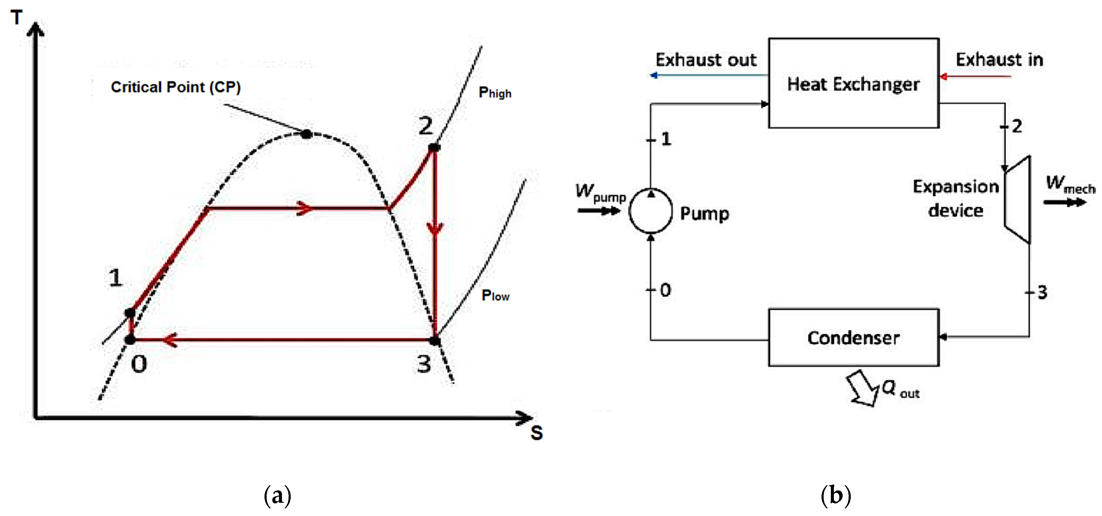
The ORC system uses a series of devices in a closed loop in order to recover energy, which can then be fed back to the engine or vehicle as required. It consists of a heat exchanger (the evaporator) that the hot gases pass through and increase the temperature of the working fluid to the extent that it changes states from liquid to superheated vapor. After the evaporator, the working fluid expands isentropically providing work in an expansion device, which is connected to an electric generator. Then the expanded vapor passes through a condenser to change its state back to liquid and reaches the pump which increases its pressure and pushes the working fluid back to the evaporator to repeat the process. Figure 1a represents a temperature-enthalpy (T-S) diagram of the Rankine cycle, while Figure 1b illustrates a schematic view of a typical Rankine cycle with all major components. Theoretically, the ORC systems can offer several benefits to the whole powertrain configuration; at best, power output of the powertrain can be increased by a maximum of approximately 15% depending on the application [26,27,28]. As a consequence of the increased efficiency of the engine, the fuel consumption can be decreased, making the ORC systems desirable for various applications [1,9,29].
Furthermore, a significant advantage of the ORC systems is that they do not depend on the pressure of the exhaust gases, as the only thing that affects the efficiency of the system are the exhaust gas temperature and mass flow rate. Comparing a conventional steam Rankine cycle to an ORC, the main difference arises from the fact that ORCs use an organic fluid (instead of water) and do not need a superheater in order for the fluid to reach the desired temperature for evaporating in order to spin the turbine [15,16,18].
5. Engine Model Calibration
In order to validate the engine model, a MATLAB (2015b, MathWorks, Natick, MA, USA, 2015) code was employed to produce a Brake Specific Fuel Consumption (BSFC) map which was identical to a chosen theoretical one. This theoretical BSFC map corresponded to the selected engine profile of a Ford 2000cc Zetec-SE DOHC engine (Ford Motors Company, London, UK), which is a four-cylinder engine with a 16-valve design and has a maximum Brake Mean Effective Pressure (BMEP) value of approximately 10 bar and a maximum engine speed at 5000 rpm. The BSFC map is shown in the figures below.
Following the selection of the theoretical engine configuration and BSFC map, the MATLAB code needed to be tested to determine the level of its accuracy. To accomplish this, the map was discretized at 29 different points that represent respective engine speed values and BMEP values. Particularly, the BSFC map was divided into five columns representing engine speeds from 1000 to 5000 rpm, and six rows representing BMEP values from 2 bar until reaching the maximum curve. This discretization is shown in Figure 2a with red dots.
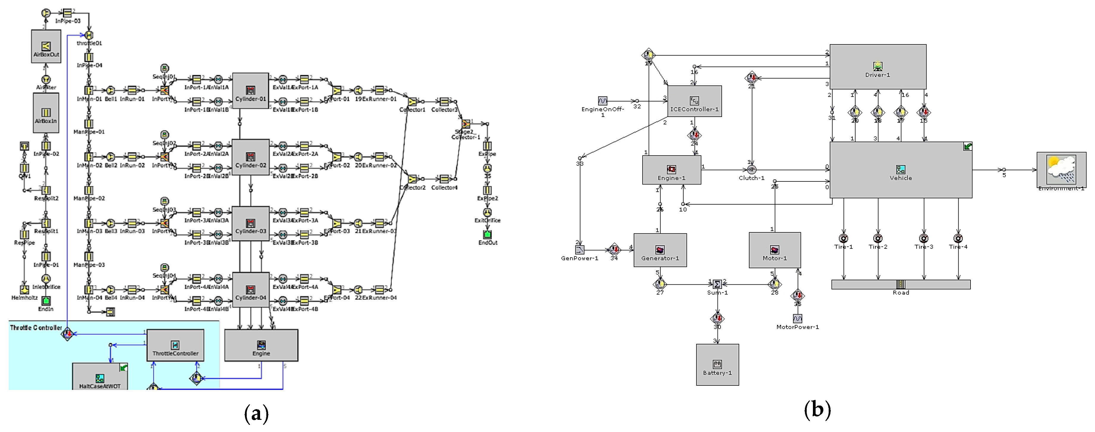
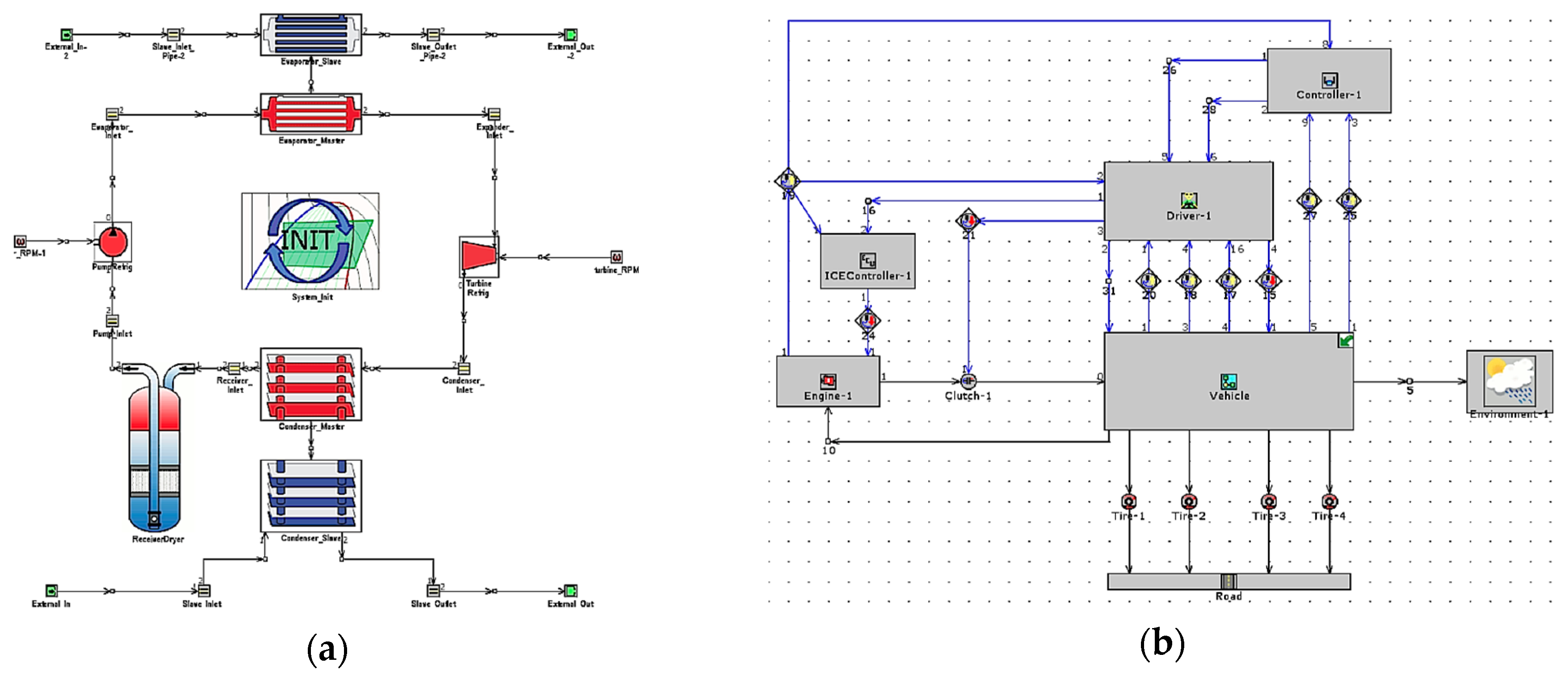
All of these 29 points correspond to different BSFC values, which were estimated visually and gathered into a table that was later used as an input in the MATLAB code. The MATLAB code can produce different performance maps, depending on the input values given from the user and for this current simulation the BSFC values were used, along with the engine speed (x-axis) and BMEP values (y-axis). After the optimization a new BSFC map was obtained as shown in Figure 2b, pointing out to the satisfactory accuracy of the code. For validation of the code results the Ford engine was modelled in GT-Power and the results correlated against the MATLAB code data. The GT-Power models of both the engine and the dynamic HEV sub-models are shown in Figure 3a,b, respectively.
The complete model included a throttle controller that was adjusted accordingly in the simulations, while the values of the inlet and exhaust ports were estimated after benchmarking and suggestions of the software. The table that included these BSFC values was given as an input to the MATLAB code and the BSFC that was generated matched the BSFC values of the theoretical model accurately. The next step after validating that the engine model can produce accurate values was to modify the model so that the new engine displacement was implemented. When the changes were implemented, the simulations were run for thirty discrete engine/load cases. It is important to point out that this work did not aim to evaluate the effect of a dynamic ORC bottoming cycle on the overall driving cycle of the vehicle, but to provide a discrete-point assessment of a conventional ORC layout for implementation in a hybrid vehicle.
6. Organic Rankine Cycle Fluid Selection and System Optimization
The selection of the appropriate organic fluid for each respective application is a demanding challenge for engineers since the performance and efficiency of the organic Rankine cycle system is seriously affected by the working fluid. However, the properties of the fluid are not the only criteria for selection, as the cost and the environmental impact of each fluid may limit the list of available fluids. As far as the cost is concerned, the engineer should decide which fluid would decrease the payback period and offer the maximum output and thermal efficiency at the same time. The properties of the organic fluids can be divided into four categories, each one of them being equally important for the efficient and safe operation of the ORC system. Thermodynamic properties of the organic fluids vary in several aspects, as do the density, viscosity, boiling point temperature, pressure, and the latent heat of vaporization. Each one of these parameters affect not only the thermal efficiency of the system, but also the design and construction of the respective internal combustion engine configuration. Critical and maximum operating conditions constitute the process-related properties and are linked with the efficiency of the organic Rankine cycle system. As far as the safety and environmental aspects are concerned, the toxicity and flammability of the fluid concerns engineers, while the global warming potential and ozone depletion danger are the major dangers for the environment. The working fluids should compromise among several criteria specified below [10,11,20,21,25,30,31,32,33,34]:
- Low condensation temperature
- Very low freezing point
- No need to superheat (dry fluid)
- Eco-friendly (low global warming potential and ozone depletion potential)
- Low flammability and toxicity
Considering all of aforementioned requirements, R245fa was selected as the working fluid in this study entirely considering prior experience and potential for widespread use. This organic fluid has no ozone impact (ODP), low global warming impact (GWP), it is non-flammable, and its thermodynamic properties fulfill the above criteria. After the selection of the working fluid, the final model was created. In GT-Power software some assumptions were considered and are shown below [2,12,13,18,22]:
- The evaporator exhaust gas initial pressure and temperature are equal with the exhaust gas outlet pressure and temperature, respectively.
- The condenser coolant initial pressure and temperature are equal with the coolant outlet pressure and temperature, respectively.
- No heat is lost to the surroundings.
The input values for the ORC model, such as exhaust temperature and exhaust mass flow rate, were obtained from a table regarding thirty different cases from 2000 cc engines at several engine speeds and BMEP ranges. Figure 4a illustrates the schematic view of the ORC system modeled in GT-Power. Data obtained included parameters such as the evaporator energy, turbine power, pump efficiency, turbine efficiency, and the pressure rise in the pump. The design parameters of the ORC system used in the simulation are presented in Table 1.
7. Driving Cycles Testing
The complete development and simulation of the ORC system model provided useful data regarding the efficiency and fuel consumption of the new, improved powertrain. This fact enables a comparison to be made between the initial engine setup and the new, improved one. The best way to compare these two powertrains is to assign them to a conventional lightweight vehicle and test them for various driving cycles. In this way the percentage difference between these two powertrains can be obtained, showing how much difference the ORC system produced. The fuel consumption benefit was the main target of this assessment, but emissions were also computed, and the major concern of this study remains the minimization of the fuel consumption of a lightweight passenger vehicle with the use of an ORC WHR recovery system.
With the use of three typical driving cycles, the fuel consumption of the initial powertrain and the powertrain with the ORC system was measured to define the extent that the ORC system benefits the vehicle. The driving cycles include:
- NEDC (New European Driving Cycle, EU)
- FTP-75 (Federal Test Procedure, US)
- US06 (a more realistic, aggressive supplement to FTP-75)
All of these driving cycles represent different driving scenarios, different durations, and average speeds. In this way, the comparison between the two powertrains (the original standalone hybrid and the hybrid powertrain equipped with the ORC WHR system) is fair and also shows where space for improvement exists if the ORC system is to be implemented in a HEV vehicle. When the developed ORC system is assigned to a HEV vehicle, different hybrid driving modes can be selected for further improved fuel economy in each driving cycle, regardless of the configuration of the HEV vehicle (series, parallel, or complex). These tests were run in GT-Power, where a virtual vehicle was modeled with an average weight of 1500 kg and several parameters set to simulate the driving scenarios. The library of the software includes all of the selected driving cycles, which ensures the precision and consistency of the results. The complete model for this test includes several parameters that were calibrated to achieve a model that fulfilled the requirements of the simulation, which is shown in Figure 4b.
8. Results and Discussion
In this section the results from the ORC simulations are presented, analyzing how efficiently the integrated system operated and where room for improvement could be identified. Lastly, the exact figures of the vehicle’s fuel consumption are shown, respectively, for each of the three different driving cycles and constitute the deciding factor for the selection of the optimum hybrid profile for the integrated powertrain. Several aspects that control the efficiency of the ORC system and how this system is combined with the IC engine to provide more power to the wheels are analyzed in this section. It is worth stating at this stage that the global assumptions considered for the ORC configuration of the HEV powertrain, namely, that even though the backpressure caused by the ORC’s evaporator placed in the exhaust pipe, and also all of the extra weight imposed by ORC components to the vehicle system, deteriorate the overall performance and the fuel consumption of the vehicle to some extent. In this early evaluation study of ORC WHR systems for HEVs, it has been assumed that the effects of these are negligible, but should be borne in mind by the reader when considering the results.
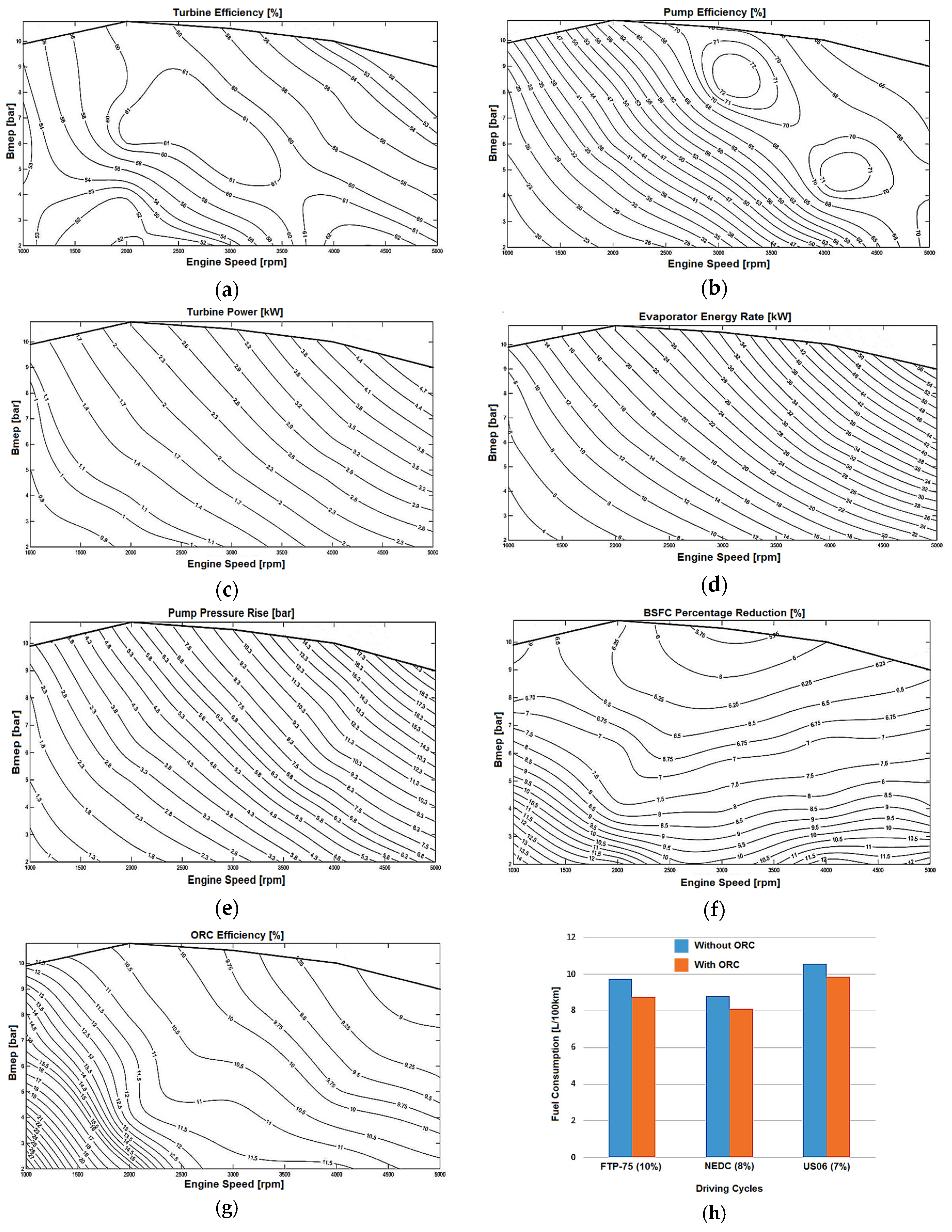
The main target set for the results of the ORC analysis is that the maximum efficiency of the turbine and the pump does not have a percentage difference of higher than 15%. Moreover, the power output of the turbine is critical, as it is added to the power output of the IC engine to provide the total power of the powertrain, so it is required to be as high as possible. Another parameter that is tested in this analysis is the pressure rise in the pump which indicates the degree to which the pump ensures the successful provision of the required pressure level throughout the entire cycle. Finally, this section concludes with the presentation of the new BSFC map of the upgraded powertrain (with ORC). The distribution of the turbine and pump efficiency is illustrated in Figure 5a,b, respectively, over the tested engine load and speed range. In the figures it can be observed how the efficiencies of these two components fluctuate with engine speed and the BMEP, as well as how the contours of constant efficiency are formed inside the plot. The maximum value of turbine efficiency is 61% and it is obtained at part-load, while the maximum efficiency of the pump is 72% at higher BMEP values and engine speeds. Great effort was expended to reach the highest efficiencies of these two components and resulted in an efficiency improvement of almost 10% from the initial model.
Figure 5c represents the allocation of the turbine power output over the tested range of engine loads and speeds. It can be observed that the maximum power is obtained at full load and high engine speeds because the exhaust gases have greater temperature and mass flow at these speeds. The plot shows that the maximum power output that the turbine produces is almost 5 kW at high engine speed and load. At part-load (around the median of 6 bar) and lower engine speeds the turbine can produce typical values of around 2.5 kW. These values may seem small at first sight, but they proved to be high enough to cause a decrease in BSFC of almost 7% under the same operating conditions.
Figure 5d,e provides information about the evaporator energy rate and the pump pressure rise, respectively. Figure 5f illustrates the BSFC reduction contour plot superimposed on the engine map. It can be interpreted from the plot that the BSFC percentage reduction differs for different engine loads and speeds with the maximum values of the reduction being obtained at the lower BMEP values, reaching a maximum 12% decrease. In addition, as the BMEP values increase at the mid-load range (6 bar), the average percentage reduction is approximately 7%, which is higher than the set target. This region is the one of highest interest as the vehicle spends most of the driving time in this region, so the 7% decrease in fuel consumption can highly benefit the hybrid vehicle. At higher engine loads and BMEP values of 9 bar, the BSFC reduction percentage is lower, but always above 5%.
One final parameter that can be examined regarding the ORC system is the overall efficiency of the system that produced the above reduction in BSFC. The efficiency of the ORC system is defined as the fraction of the turbine power output over the evaporator energy rate, showing how efficiently the available energy is used inside the ORC WHR system. However, as for this investigation a four-cylinder 2000 cc engine was selected, the available energy rate is limited and the constraints inside the system are greater when compared to a larger (commercial-type) diesel engine (which can exploit the full potential of the system and reach higher efficiencies). In order to mitigate this drawback, the ORC system has been modified to give the higher possible efficiency.
Figure 5g shows the distribution of the ORC efficiency superimposed on the engine map. It can be seen that, overall, the ORC efficiency fluctuates at different engine speeds and loads, as well as the efficiency values are not very high. At lower engine speeds and BMEP values the ORC efficiency reaches a maximum of 27%, which is expected because the energy rate is fairly low, while at least the simulated turbine power has already reached near-maximum efficiencies even from lower loads and speeds. As the engine speeds and loads rise, the evaporator energy rate increases, resulting in the decrease of the efficiency because the turbine power is not increasing accordingly due to restrictions in the ORC system design and in the exhaust mass flow rate and temperature. The ORC efficiency reaches an average value of 10.5% at the engine speed of 3000 rpm and BMEP of 6.5 bar, which is an important region of the powertrain operating points. A further increase in engine speed and BMEP values show an efficiency of 9%, which is the minimum percentage obtained in this study and for the entire engine operating range. In general, the efficiency of the ORC is significant, but it is not reaching its full potential due to several inherent limitation of the smaller capacity powertrain. However, with this efficiency distribution, the ORC system is able to produce an average decrease in BSFC values of 7%, which is significant compared to a conventional HEV configuration.
Hereinafter, the overall results of the project are further interpreted in order to obtain a clear ORC WHR system characterization of its performance and benefit that it brings to the conventional HEV architecture. In addition, the discussion indicates how the different hybrid modes of the vehicle should be chosen in order to further decrease the fuel consumption of the vehicle; specifically, the discussion identifies which hybrid mode should be chosen in the different driving scenarios, such that the vehicle can operate more efficiently, while consuming the minimum amount of fuel.
During the various driving cycle tests that were performed in the engine simulation software, the vehicle model was run with and without the ORC configuration, so that the absolute difference between these two setups could be distinguished. Moreover, the three different driving cycle tests can validate the efficiency of the whole powertrain in different driving conditions, providing useful information about the hybrid mode which emerges in each case. Finally, these tests revealed possible areas where the ORC system could be further optimized for greater HEV vehicle benefit.
For the FTP-75 driving cycle test the obtained data from the analysis showed that the fuel consumption of the vehicle without the ORC system was 9.74 L/100 km. When the ORC system was included in the powertrain, the new fuel consumption was calculated to be 8.76 L/100 km, which is almost 1 L less per 100 km.
On the other hand, on the NEDC, the results showed that the fuel consumption without the ORC system was 8.79 L/100 km, while when the ORC system was included in the analysis the new fuel consumption was 8.07 L/100 km. The difference between these two values is almost 0.8 L/100 km.
The final driving cycle test was the US06, giving a fuel consumption of 10.57 L/100 km without the ORC system. When the ORC system was added in the analysis, the improved fuel consumption was decreased to 9.84 L/100 km, which is almost 0.7 L/100 km less. This driving cycle is more aggressive than the previous two, which is why the powertrain reached higher fuel consumption values in comparative terms to NEDC and FTP-75.
Moreover, the results from the driving cycle analysis can assist the understanding of how the ORC system cooperates with the engine under different loads, accelerations, and decelerations. The three selected driving cycles constitute a representative example of driving regulations in use today and which were required to validate HEV performance with the novel component (ORC WHR system).
In Figure 5h the bar charts illustrate the differences in fuel consumption between the original HEV engine and the ORC-equipped equivalent in order to minimize fuel consumption. Furthermore, the percentage difference is calculated, so that the absolute difference of the improved powertrain can be differentiated. This bar chart includes information for all three of the driving cycle tests and presents the exact amount of burned fuel per 100 km of driving. It can be noticed that in all of the driving cycle scenarios, the fuel consumption was decreased after the implementation of the ORC system. The largest reduction was found to be in the FTP-75 driving cycle and the calculation of the absolute percentage difference showed a 10% lower fuel requirement for 100 km. The NEDC required the least amount of fuel, as it is not as aggressive as the other two cycles. Moreover, in this driving cycle the ORC system improved the fuel consumption by 8%, which is a significant reduction if the strict European regulations are taken into consideration. Finally, the US06 driving cycle required the most fuel overall, but the ORC system managed to lower the fuel consumption of the vehicle by 7%, which resulted in a drop of fuel consumption below 10 L/100 km.
A closer look into the three driving cycles was required to reveal the driving strategy needed in order to maximize the powertrain performance in the electric hybrid vehicle. Taking into account the three major hybrid operation modes, which are the traction mode, braking mode, and coasting mode, the driver can be guided in how to handle the accelerator pedal, the braking pedal, and the clutch pedal to maximize the efficiency of the overall vehicle.
As far as the NEDC is concerned, it can be identified that it consists of numerous accelerations and decelerations, and the average cruising speed is 60 km/h. This driving cycle profile can exploit the braking and coasting operation modes of the hybrid configuration to gain advantages regarding the fuel consumption of the vehicle. During the decelerations the brake should be lightly applied and this will lead to the battery being charged by dissipating the braking energy and, hence, more power can be delivered to the wheels during the acceleration zones. Moreover, the driver can use the coasting mode, while no brakes or throttle are applied, before reaching the deceleration zones and prevent, in that way, the engine from burning fuel in a non-beneficial manner.
The FTP-75 driving cycle has a complicated profile of accelerations and decelerations, which makes it difficult for the driver to adopt the optimum driving strategy. However, as there are multiple fluctuations in the speed profile of this cycle, the driver can exploit the braking mode to charge the battery of the hybrid setup. This gained power can be used during steep acceleration gradients to assist the work of the IC engine, leading to less fuel being burned during the numerous accelerations. As long as there are no flat speed regions in this driving cycle, the coasting mode can hardly be applied and cannot influence a further reduction of the fuel consumption.
Finally, the US06 driving cycle results exhibit lower fluctuations in the speed profile compared to the FTP-75, which means that the coasting mode can be applied, offering significant benefits in fuel consumption reduction. This driving cycle pushes the vehicle to reach high speeds of more than 120 km/h, which undoubtedly increases the consumption of fuel of the vehicle. In order to counteract this, judicious use of the accelerator pedal would be recommended, along with use of the power of the electric motor to assist with significant accelerations. On the other hand, the braking mode can be used to gather the essential electric power in the battery and the coasting mode can be used when the car needs to decrease its speed without the strict application of the brakes.
9. Conclusions
A simulation study has been conducted to prove that a waste heat recovery method can be employed in a hybrid electric vehicle and offer significant benefits regarding the overall performance of the vehicle, primarily in terms of fuel consumption reduction. An organic Rankine cycle-based waste heat recovery system was chosen as the method by which to extract further work from the conventional elements of this hybrid powertrain. After utilizing this system in the powertrain, the results showed the overall fuel consumption of the vehicle was decreased significantly. In the simulation the engine was run for three different driving cycle tests, including FTP-75, NEDC, and US06, in order to validate the real improved performance of the developed powertrain in different driving conditions, and ultimately led to an efficient driving strategy for the driver of the electric hybrid vehicle that could lower fuel consumption even further.
Acknowledgments
This work was not financially supported or funded by any organization/company and the authors would like to acknowledge Marios Kalamakis who performed the simulation procedure.
Author Contributions
Amin Mahmoudzadeh Andwari and Vahid Esfahanian have written the paper context and performed results presentation. Apostolos Pesiridis and Apostolos Karvountzis-Kontakiotis have carried out the design of experiment in the simulation and have extracted the data analysis.
Conflicts of Interest
The authors declare no conflict of interest.
References
- Pesiridis, A. Automotive Exhaust Emissions and Energy Recovery; Nova Science Publishers: New York, NY, USA, 2014. [Google Scholar]
- Oyewunmi, O.A.; Markides, C.N. Thermo-economic and heat transfer optimization of working-fluid mixtures in a low-temperature organic Rankine cycle system. Energies 2016, 9, 448. [Google Scholar] [CrossRef]
- Andwari, M.A.; Aziz, A.A.; Farid, M.; Said, M.; Zulkarnain, A.L. Controlled auto-ignition combustion in a two-stroke cycle engine using hot burned gases. Appl. Mech. Mater. 2013, 388, 201–205. [Google Scholar] [CrossRef]
- Teng, H.; Regner, G.; Cowland, C. Waste heat recovery of heavy-duty diesel engines by organic Rankine cycle Part I: Hybrid energy system of diesel and Rankine engines. SAE Tech. Pap. 2007. [Google Scholar] [CrossRef]
- Feneley, A.J.; Pesiridis, A.; Andwari, A.M. Variable geometry turbocharger technologies for exhaust energy recovery and boosting—A review. Renew. Sustain. Energy Rev. 2017, 71, 959–971. [Google Scholar] [CrossRef]
- Kulkarni, K.; Sood, A. Performance analysis of organic Rankine cycle (ORC) for recovering waste heat from a heavy duty diesel engine. SAE Tech. Pap. 2015. [Google Scholar] [CrossRef]
- Stanzel, N.; Streule, T.; Preißinger, M.; Brüggemann, D. Comparison of cooling system designs for an exhaust heat recovery system using an organic Rankine cycle on a heavy duty truck. Energies 2016, 9, 928. [Google Scholar] [CrossRef]
- Amin, M.A.; Azhar, A.A. Homogenous Charge Compression Ignition (HCCI) technique: A review for application in two-stroke gasoline engines. Appl. Mech. Mater. 2012, 165, 53–57. [Google Scholar] [CrossRef]
- Zhang, X.; Zeng, K.; Bai, S.; Zhang, Y.; He, M. Exhaust recovery of vehicle gasoline engine based on organic Rankine cycle. SAE Tech. Pap. 2011. [Google Scholar] [CrossRef]
- Zhou, L.; Tan, G.; Guo, X.; Chen, M.; Ji, K.; Li, Z.; Yang, Z. Study of energy recovery system based on organic Rankine cycle for hydraulic retarder. SAE Tech. Pap. 2016. [Google Scholar] [CrossRef]
- Ringler, J.; Seifert, M.; Guyotot, V.; Hübner, W. Rankine cycle for waste heat recovery of IC engines. SAE Int. J. Engines 2009, 2, 67–76. [Google Scholar] [CrossRef]
- Shu, G.; Zhao, J.; Tian, H.; Wei, H.; Liang, X.; Yu, G.; Liu, L. Theoretical analysis of engine waste heat recovery by the combined thermo-generator and organic Rankine cycle system. SAE Tech. Pap. 2012. [Google Scholar] [CrossRef]
- Sprouse, C., III; Depcik, C. Organic Rankine cycles with dry fluids for small engine exhaust waste heat recovery. SAE Int. J. Altern. Powertrains 2013, 2, 96–104. [Google Scholar] [CrossRef]
- Zhang, X.; Mi, C. Vehicle Power Management; Modeling, Control and Optimization; Springer: London, UK, 2011. [Google Scholar]
- Arsie, I.; Cricchio, A.; Pianese, C.; Ricciardi, V.; De Cesare, M. Modeling and optimization of organic Rankine cycle for waste heat recovery in automotive engines. SAE Tech. Pap. 2016. [Google Scholar] [CrossRef]
- Boretti, A. Improving the efficiency of turbocharged spark ignition engines for passenger cars through waste heat recovery. SAE Tech. Pap. 2012. [Google Scholar] [CrossRef]
- Kirmse, C.J.W.; Oyewunmi, O.A.; Haslam, A.J.; Markides, C.N. Comparison of a novel organic-fluid thermofluidic heat converter and an organic Rankine cycle heat engine. Energies 2016, 9, 479. [Google Scholar] [CrossRef]
- Cipollone, R.; Di Battista, D.; Perosino, A.; Bettoja, F. Waste heat recovery by an organic Rankine cycle for heavy duty vehicles. SAE Tech. Pap. 2016. [Google Scholar] [CrossRef]
- Cochran, D.L. Working fluids for high temperature, Rankine cycle, space power plants. SAE Tech. Pap. 1961. [Google Scholar] [CrossRef]
- El Chammas, R.; Clodic, D. Combined cycle for hybrid vehicles. SAE Tech. Pap. 2005. [Google Scholar] [CrossRef]
- Lodwig, E. Performance of a 35 HP organic Rankine cycle exhaust gas powered system. SAE Tech. Pap. 1970. [Google Scholar] [CrossRef]
- Heywood, J.B. Internal Combustion Engine Fundamentals; McGraw-Hill: New York, NY, USA, 1988. [Google Scholar]
- Chen, T.; Zhuge, W.; Zhang, Y.; Zhang, L. A novel cascade organic Rankine cycle (ORC) system for waste heat recovery of truck diesel engines. Energy Convers. Manag. 2017, 138, 210–223. [Google Scholar] [CrossRef]
- Hsieh, J.-C.; Fu, B.-R.; Wang, T.-W.; Cheng, Y.; Lee, Y.-R.; Chang, J.-C. Design and preliminary results of a 20-kW transcritical organic Rankine cycle with a screw expander for low-grade waste heat recovery. Appl. Therm. Eng. 2017, 110, 1120–1127. [Google Scholar] [CrossRef]
- Read, M.; Smith, I.; Stosic, N.; Kovacevic, A. Comparison of organic Rankine cycle systems under varying conditions using turbine and twin-screw expanders. Energies 2016, 9, 614. [Google Scholar] [CrossRef]
- Shu, G.; Wang, X.; Tian, H. Theoretical analysis and comparison of rankine cycle and different organic rankine cycles as waste heat recovery system for a large gaseous fuel internal combustion engine. Appl. Therm. Eng. 2016, 108, 525–537. [Google Scholar] [CrossRef]
- Wang, E.; Yu, Z.; Zhang, H.; Yang, F. A regenerative supercritical-subcritical dual-loop organic Rankine cycle system for energy recovery from the waste heat of internal combustion engines. Appl. Energy 2017, 190, 574–590. [Google Scholar] [CrossRef]
- Yang, F.; Zhang, H.; Yu, Z.; Wang, E.; Meng, F.; Liu, H.; Wang, J. Parametric optimization and heat transfer analysis of a dual loop ORC (organic Rankine cycle) system for CNG engine waste heat recovery. Energy 2017, 118, 753–775. [Google Scholar] [CrossRef]
- Kolasiński, P.; Błasiak, P.L.; Jozef, R. Experimental and numerical analyses on the rotary vane expander operating conditions in a micro organic Rankine cycle system. Energies 2016, 9, 606. [Google Scholar] [CrossRef]
- Reck, M.; Randolf, D. An organic Rankine cycle engine for a 25-passenger bus. SAE Tech. Pap. 1973. [Google Scholar] [CrossRef]
- Thaddaeus, J.; Pesiridis, A.; Karvountzis-Kontakiotis, A. Design of variable geometry waste heat recovery turbine for high efficiency internal combustion engine. Int. J. Sci. Eng. Res. 2016, 7, 1001–1017. [Google Scholar]
- Karvountzis-Kontakiotis, A.; Pesiridis, A.; Zhao, H.; Franchetti, B.; Pesmazoglou, I.; Alshammari, F.; Tocci, L. Effect of an ORC waste heat recovery system on diesel engine fuel economy for off-highway vehicles. In Proceedings of the SAE World Congress, Detroit, MI, USA, 4–6 April 2017. [Google Scholar]
- Franchetti, B.; Pesiridis, A.; Pesmazoglou, I.; Sciubba, E.; Tocci, L. Thermodynamic and technical criteria for the optimal selection of the working fluid in a mini-ORC. In Proceedings of the 29th International Conference on Efficiency, Cost, Optimization, Simulation and Environmental Impact of Energy Systems (ECOS 2016), Portorož, Slovenia, 19–23 June 2016. [Google Scholar]
- Karvountzis-Kontakiotis, A.; Alshammari, F.; Pesiridis, A.; Franchetti, B.; Pesmazoglou, I.; Tocci, L. Variable geometry turbine design for off-highway vehicle organic Rankine cycle waste heat recovery. In Proceedings of the THIESEL 2016, Valencia, Spain, 13–16 September 2016. [Google Scholar]
Figure 1.
Working principle of typical Rankine cycle: (a) temperature-enthalpy diagram; and (b) schematic of Rankine cycle components.
Figure 1.
Working principle of typical Rankine cycle: (a) temperature-enthalpy diagram; and (b) schematic of Rankine cycle components.

Figure 2.
BSFC map of Ford 2.0 L Zetec-SE DOHC engine: (a) predicted and discretized BSFC map of 29 points; and (b) the BSFC map given from optimized MATLAB code.
Figure 2.
BSFC map of Ford 2.0 L Zetec-SE DOHC engine: (a) predicted and discretized BSFC map of 29 points; and (b) the BSFC map given from optimized MATLAB code.
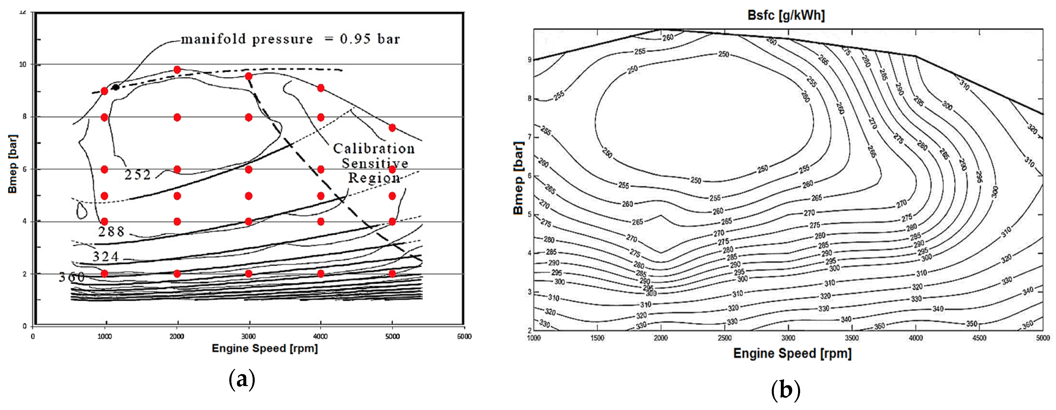
Figure 3.
Ford 2.0 L Zetec-SE DOHC Engine modeled in GT-Power software (7.3b2, Gamma Technologies LLC, Westmont, IL, USA, 2015): (a) integrated conventional engine’s components; (b) dynamic Hybrid Electric Vehicle (HEV) subsystem integrated with the base engine components.
Figure 3.
Ford 2.0 L Zetec-SE DOHC Engine modeled in GT-Power software (7.3b2, Gamma Technologies LLC, Westmont, IL, USA, 2015): (a) integrated conventional engine’s components; (b) dynamic Hybrid Electric Vehicle (HEV) subsystem integrated with the base engine components.

Figure 4.
Schematic view of the engine system model in GT-Power: (a) organic Rankine cycle system sub-model; and (b) complete model used for driving cycle testing.
Figure 4.
Schematic view of the engine system model in GT-Power: (a) organic Rankine cycle system sub-model; and (b) complete model used for driving cycle testing.

Figure 5.
Schematic view of the engine system model in GT-Power code: (a) turbine efficiency distribution; (b) pump efficiency distribution; (c) turbine power distribution; (d) EVAPORATOR energy rate; (e) Pump pressure rise; (f) BSFC percentage reduction distribution; (g) ORC efficiency distribution; and (h) fuel consumption per driving cycle.

Table 1.
Organic Rankine cycle component design parameters using R245fa refrigerant.
| Design Parameters | ORC’s Main Components | |||||
|---|---|---|---|---|---|---|
| Evaporator (Slave) | Evaporator (Master) | Condenser (Slave) | Condenser (Master) | Turbine Expander | Pump | |
| Average Inlet Pressure (bar) | 1.00102 | 24.9 | 2.15 | 3.28 | 24.3 | 2.6 |
| Average Outlet Pressure (bar) | 1 | 24.3 | 2 | 2.6 | 3.28 | 24.9 |
| Average Pressure Drop (bar) | 0.0010197 | 0.631 | 0.148264 | 0.674932 | - | - |
| Average Inlet Temperature (K) | 973.1 | 315.8 | 296.1 | 405.1 | 445.2 | 314.1 |
| Average Outlet Temperature (K) | 450.7 | 445.2 | 302.6 | 314.1 | 405.263 | 315.8 |
| Average Mass Flow Rate (g/s) | 140 | 269.2 | 3394.6 | 269.3 | 0.269 | 0.269 |
| Combined Energy Rate out of Fluid (kW) | 78.7 | −78.7 | −73.2 | 73.2 | - | - |
| Average Speed (rpm) | - | - | - | - | 1350 | 2000 |
| Average Map Pressure Ratio | - | - | - | - | 7.37 | - |
| Average Efficiency (%) | - | - | - | - | 51.61 | 61.42 |
| Average Power (kW) | - | - | - | - | 5.3 | 0.75 |
| Average Pressure Rise (bar) | - | - | - | - | - | 22.3 |
| Heat Exchanger Volume (L) | 11.75 | 3.33 | 6.5 | 5.65 | - | - |
| Heat Exchanger Reference Length (m) | 0.007 | 0.007 | 0.003 | 0.003 | - | - |
| Heat Exchanger Heat Transfer Area (m2) | 1.87 | 1.87 | 9.33 | 9.33 | - | - |
| Heat Exchanger Flow Area (m2) | 0.0138 | 0.0038 | 0.02 | 0.02 | - | - |
© 2017 by the authors. Licensee MDPI, Basel, Switzerland. This article is an open access article distributed under the terms and conditions of the Creative Commons Attribution (CC BY) license (http://creativecommons.org/licenses/by/4.0/).
Share and Cite
MDPI and ACS Style
Mahmoudzadeh Andwari, A.; Pesiridis, A.; Karvountzis-Kontakiotis, A.; Esfahanian, V. Hybrid Electric Vehicle Performance with Organic Rankine Cycle Waste Heat Recovery System. Appl. Sci. 2017, 7, 437. https://doi.org/10.3390/app7050437
AMA Style
Mahmoudzadeh Andwari A, Pesiridis A, Karvountzis-Kontakiotis A, Esfahanian V. Hybrid Electric Vehicle Performance with Organic Rankine Cycle Waste Heat Recovery System. Applied Sciences. 2017; 7(5):437. https://doi.org/10.3390/app7050437
Chicago/Turabian StyleMahmoudzadeh Andwari, Amin, Apostolos Pesiridis, Apostolos Karvountzis-Kontakiotis, and Vahid Esfahanian. 2017. "Hybrid Electric Vehicle Performance with Organic Rankine Cycle Waste Heat Recovery System" Applied Sciences 7, no. 5: 437. https://doi.org/10.3390/app7050437
Note that from the first issue of 2016, this journal uses article numbers instead of page numbers. See further details here.