
An Improved Radio Resource Management with Carrier Aggregation in LTE Advanced


1
Department of Electrical Engineering, Faculty of Engineering, University of Malaya, Kuala Lumpur 50603, Malaysia
2
Department of Computer Science & Engineering, Faculty of Science & Engineering, East West University, Dhaka 1212, Bangladesh
*
Author to whom correspondence should be addressed.
Appl. Sci. 2017, 7(4), 394; https://doi.org/10.3390/app7040394
Submission received: 17 February 2017
/
Revised: 6 April 2017
/
Accepted: 12 April 2017
/
Published: 14 April 2017
Abstract
:Long term evolution-advanced (LTE-A) system introduces carrier aggregation (CA) technique to improve the user throughput by aggregating multiple component carriers (CCs). Previous research works related to downlink radio resource allocation with carrier aggregation have not considered the delay factor and the error probability. Therefore, the previous methods are unable to provide better quality of service (QoS) compared to the LTE-A standard. This paper considers the radio resource management problem by zooming into the head of line delay, probability of packet loss, and the delay threshold for different types of data. In doing this, several constraints are imposed following the specifications of LTE-A system. Hence, an improved method is developed in this study to enhance the system throughput and to maintain the computational complexity. Extensive simulations were carried out with other well-known methods to verify the overall performance of the proposed method. The result obtained indicates that the proposed method outperforms the previous methods in the measurement of average user throughput, average cell throughput, fairness index, and spectral efficiency.
1. Introduction
LTE is introduced as the fourth generation (4G) mobile communication by 3GPP in Release-8 (Rel-8) which is based on the Orthogonal Frequency Division Multiple Access (OFDMA) technology. With some modification in Release-9 (Rel-9), LTE has set a benchmark in achieving peak downlink data rate of 300 Mbps and better (QoS) than the 3G network. However, the current forecast of future demand indicates that the immense challenge is far beyond the initial establishment of 4G. Due to both the explosion of mobile data traffic along with new services and applications, it is necessary to upgrade the LTE system. 3GPP initiated LTE-A in Release-10 (Rel-10), which fulfilled the requirements of International Mobile Telecommunication-Advanced (IMT-Advanced) with a major enhancement that included a peak data rate of 1 Gbps in downlink and 500 Mbps in uplink [1].
To reach out with the future demands and to implement the IMT-Advanced requirements, LTE-A introduced some new technologies along with the enhancement of previous technologies. In Rel-10, LTE-A proposed CA for supporting wider bandwidth up to 100 MHz [2]. This technology is also known as channel aggregation, which uses multiple (maximum five) CCs of different frequencies joined together to form a higher overall transmission bandwidth and is used to provide an improved throughput as required for LTE-A system. Each CC may appear as LTE carrier to the legacy users while LTE-A users are able to transmit and receive on several CCs simultaneously. CA is designed to be backward compatible which means that legacy Rel-8 and Rel-9 users can co-exist with LTE-A users on part of the total bandwidth. Moreover, CA supports the frequencies previously occupied by other systems, such as UMTS and GSM for possible CC aggregation [3]. Therefore, the scheduler can allocate resources on any one of the available CCs with a different bandwidth (maximum 20 MHz) to Rel-8 and Rel-9 users. CA will allow the operator to provide additional capacity without causing any unfavorable impact on the legacy LTE (Rel-8 and Rel-9) users.
LTE-A supports three types of CA, namely intra-band contiguous, intra-band non-contiguous and inter-band contiguous or non-contiguous. Intra-band contiguous is the simplest CA deployment, which aggregates multiple adjacent CCs in the same operating band. It requires less power and lower costs than the other two types. It can be implemented without making much change to the LTE physical layer structure [4]. Moreover, it is possible to use a single transceiver to utilize the continuous CCs for an LTE-A user. Intra-band non-contiguous CA combines multiple non-adjacent CCs in the same operating band. The multicarrier component is no longer considered as a single signal and therefore, it requires more transceivers which adds more complexity and cost. Inter-band CA aggregates multiple CCs in separate operating bands. These CCs in different bands can be contiguous or non-contiguous. More advanced multiple transceivers are required, which increases the complexity, cost, and power requirement. This paper considers intra-band contiguous CA technique for simplicity.
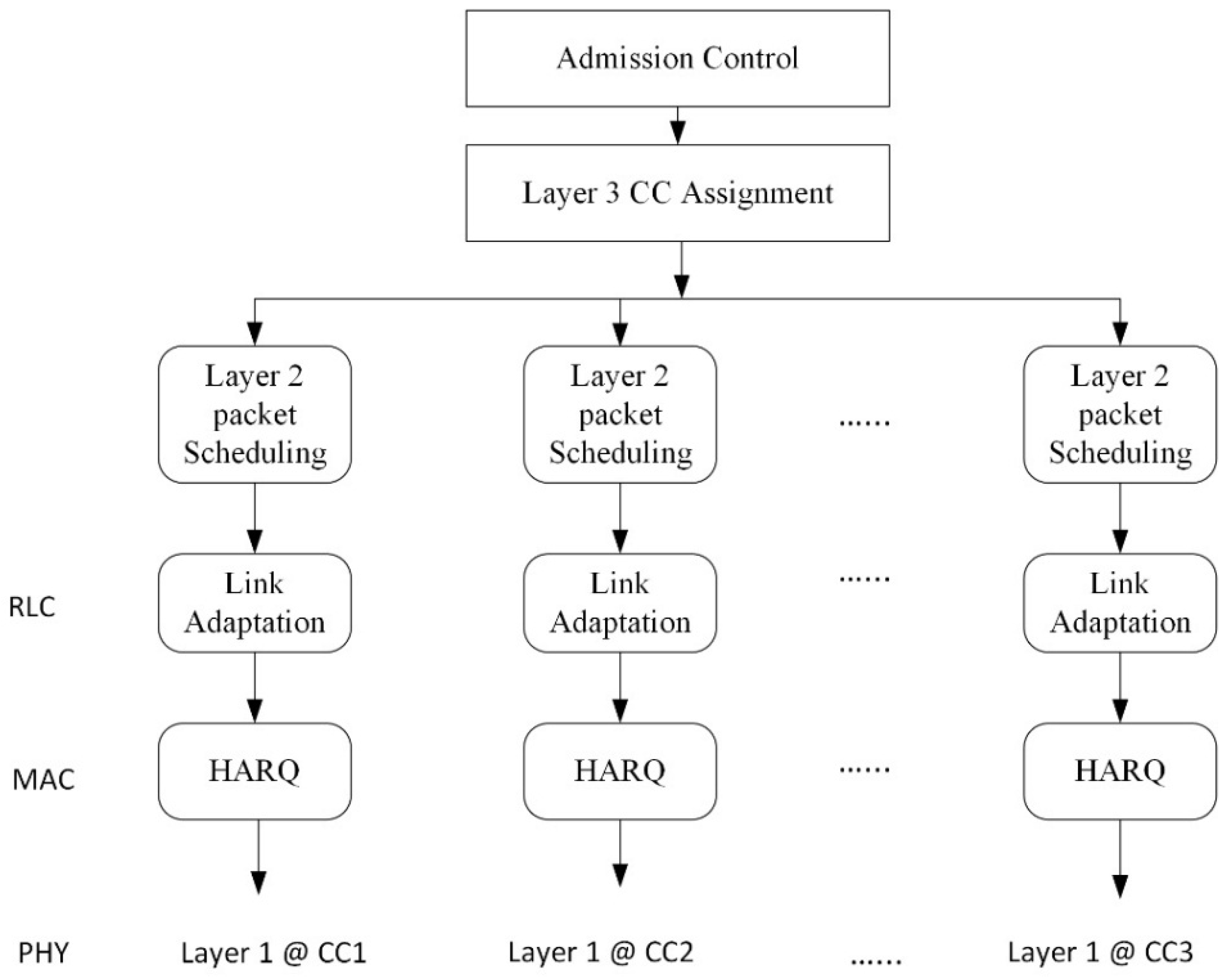
Multiple CC assignment to a user introduces some new challenges related to the functionalities of radio resource management (RRM). Figure 1 shows the RRM framework of multiple CCs aggregated in LTE-A system. The admission control which is executed by Evolved NodeB (eNB) determines whether to accept or reject the incoming connection. Thereafter, it allocates multiple CCs to the incoming user based on different criteria, such as QoS requirements and the terminal capability of different users. Moreover, each of the users will experience various channel conditions affected by geographical location and various types of noise and interference. Each CC operates independently in separate RRM blocks. Therefore, each of the CCs will have an independent packet scheduling algorithm which performs the allocation of time-frequency resources of each CC—called resource blocks (RB)—to each user at every transmission time interval (TTI). An efficient scheduling algorithm can resolve conflict amongst the users and eNBs and it is also important to maximize the system throughput, fairness, spectral efficiency, and to reduce the delay among the users.
Channel dependent packet schedulers are more accurate in real life scenarios as they consider more parameters than channel independent schedulers. Most of the previous researchers have used proportional fairness (PF) [5,6,7], Round Robin (RR) [8,9] and other algorithms [10,11,12,13,14,15,16,17] for resource allocation with CA in an LTE-A system. However, some important parameters, such as packet delay or error rate are not considered. This paper implements Modified Largest Weighted Delay First (MLWDF) algorithm to ensure ideal throughput to the system and to maintain fairness to all users [18,19]. This scheduler largely depends on QoS and packet delay. A QoS-related ‘discard timer’ is set on all packets when they arrive to the eNodeB. The packets being waited in the queue until they are successfully transmitted or the ‘discard timer’ expires. This queueing delay (elapsed time since the user packet arrived in the queue) is denoted as the head of line (HOL) delay in the MLWDF algorithm [20]. If the HOL delay exceeds the predefined delay threshold of the user application, Packet Data Convergence Protocol (PDCP) layer discards the user packets according to the standard [21]. The PDCP entity in the receiving end will not wait for any packet which is not transmitted. MLWDF algorithm is a throughput optimal algorithm as it makes scheduling decisions based on the queue situation and the rate of successful packet transmission. This algorithm also gives priority to the users who have the best channel condition to prevent the data loss before it reaches a certain limit in the queue. Link Adaptation (LA) and Hybrid ARQ (HARQ) are working independently for each CC. LA based on adaptive modulation and coding (AMC) can adapt the modulation and coding scheme (MCS) [22]. The higher the SINR (Signal-to-Interference plus Noise Ratio), the higher the coding rate and spectral efficiency.
The proposed method calculates gain for all users to assign the CC with highest gain. Queue length of individual CC is also measured to balance the load of all CCs. Consideration of the queue length also allows the scheduler to reduce the packet waiting time in the queue and significantly improves the QoS. Then HOL delay and the probability of packet loss are calculated to find out the highest metric for individual users [23]. Subsequently, CCs are assigned to the user according to the metric until it reaches any terminating condition.
The rest of the paper is constructed as follows. In Section 2, related works on radio resource management are discussed. In Section 3, new greedy-based model with computational complexity is proposed. Discussion on simulation settings and obtained results are reported in Section 4. Some limitations and future plans are mentioned in Section 5 and finally, Section 6 concludes the paper.
2. Related Work
Downlink radio resource management has a major impact on the overall performance of the mobile network. Therefore, a wide range of study has been conducted by researchers on various aspects of resource management. A good number of researchers have used PF and modified algorithms for packet scheduling with different approaches of CC selection. Joint scheduling also has been proposed to enhance the QoS.
The Circular Selection (CS) scheme is used in [9] where CCs have been assigned circularly to the users. The authors proposed CC coupling method to balance the load. This method first determines whether the particular CC is idle or busy. If any CC is idle, the load from the other CC will be transferred to the idle one until the CC turns into the busy state. This coupling occurs in every TTI. Round Robin packet scheduling algorithm is chosen for allocating the RB. Compared to other schemes, the authors claim that their method provided higher throughput and improved coverage performance due to efficient balance of the load over multiple CCs. However, in the case of different packet size of user, the efficiency can be decreased. Moreover, it significantly increases the power consumption of the users and the signal processing complexity.
In [24], CCs have been assigned to a lower frequency at first, then users with higher CQI (Channel Quality Indicator) values move to a higher frequency based on the load of all other CCs. The authors consider two frequencies (2 GHz and 5 GHz) for the proposed method. When a user arrives, the scheduler directly allocates the 2 GHz band, then it checks the load in both bands. If the load is lower in 5 GHz than in 2 GHz, the user with the highest CQI value will be assigned to the 5 GHz band. In case of higher network loads, the users with the lowest CQI value will be moved to the 2 GHz band as propagation loss is typically lower than 5 GHz. Load is calculated based on the availability of the resources for the cell and utilized by the users. Although this approach increases the computational complexity and it does not consider the multi-band approach.
In [25], user grouping PF algorithm (UG-PF) is proposed to improve fairness among users. In this model, path-loss with a certain threshold and coverage of each CC is calculated. Then, the users are divided into some specific groups according to the number of available CCs which can be assigned to the users from their location. The cell-edge user groups are also allowed to access the RBs in the CCs of lower frequencies. Moreover, the users with poor CQI value can obtain higher throughput and better fairness among the users by this algorithm compared with the conventional PF algorithm. However, the average cell throughput can go down by allocating a lot of RBs to users with poor CQI. A generalized PF based Cross-CC PF is proposed in [7] to adapt the level of fairness between users with different aggregation capabilities and with different channel conditions. This method selects CC randomly for users and distributes the load across all CCs. It proves that when the CC selection is predetermined for a user, Cross-CC PF is a better scheduler to improve the throughput. The proposed method requires the exchange of data on the previous user throughput for all CCs. Considering that throughput of all CCs makes the scheduling metric of LTE-A users smaller compared with the basic PF. Their results show better fairness to the users and it is also shown that Cross-CC PF boosts the average user throughput and coverage performance without sacrificing the average cell throughput.
Absolute and relative policy is proposed in [26] by considering the signal quality of the CC. Their method divided the cell coverage area into two different cells, named ‘primary serving cell (PCell)’ with designated primary CC and ‘secondary serving cell (SCell)’ with secondary CC. When an LTE-A user arrives, eNB firstly attaches it with a PCell as the authors assumed that PCell has best signal quality. According to their absolute policy, when the signal quality of a CC is higher or lower than a predefined absolute threshold, the CC is added or removed to the user respectively. On the other hand, based on the relative policy, if the signal quality of a CC is offset higher or lower than the corresponding CC of PCell, the CC is added or removed respectively. However, it is a challenge to determine the threshold or offset value.
In [27], the authors proposed a greedy method to maximize the throughput with PF packet scheduling algorithm. Their method considered link adaptation jointly with CC assignment and RB allocation. After calculating the gain of all possible combinations, CCs have been assigned to users which have the highest gain. Regarding RB allocation, the method checked that whether or not the weighted transmission rate of user with maximum gain is higher than currently assigned RB. However, the authors considered that all CCs have an equal number of RB and all users have similar capabilities which are currently unrealistic assumptions compared to the real world. The results are compared with the Least Lord (LL) and Random Carrier (RC) methods, and a modified algorithm named SS. Table 1 shows the summary of previous studies regarding carrier aggregation methods with different CC selection approaches and packet schedulers.
3. System Model
3.1. Problem Formulation
This paper implements MLWDF for downlink radio resource management. MLWDF is a throughput-optimal scheduling algorithm which considers packet delay and probability of packet loss along with instantaneous and previous throughput of the user. The scheduler maximizes the utility function to achieve better QoS, where ri(t) is the instantaneous transmission rate of user i at TTI t and is the previous average transmission rate. For convenience, Table 2 shows the symbols used in this paper.
Let i, j, k, l be the user, CC, RB, and MSC index, respectively where i ϵ Q = {1, …., Q}, j ϵ R = {1, …., R}, k ϵ S = {1, …., S} and l ϵ T = {1, …., T}. In the above function, ri(t)/ can be denoted as the weighted transmission rate Wi,j,k,l for user i, CC j, RB k, and MSC l. For simplification, the TTI t is removed from the rest of the paper. The resource scheduling is defined by solving the following function according to the MLWDF algorithm.
Subjected to the following conditions:
where ψi,j,k,l is a variable to indicate whether or not CC j, RB k, and MSC l is assigned to user i, Di,j is the HOL delay of user i and CC j. The condition in (2) states that each RB of a CC can be assigned to maximum one user. The condition in (3) assures that one user can use only one MSC with assigned CC and RB. The condition in (4) restricts the user not to be assigned more than m number of CC. The condition in (5) mentions that HOL delay must be lower than the delay threshold. By the definition of the MLWDF algorithm, αi in Equation (1) is a variable which allows the scheduler to control the distribution of packet delay [18]. Increasing the value of αi for user i, while keeping the values for other users unchanged, reduces the packet delay for user i at the cost of increasing the waiting time for other users. The variable αi is defined in the following Equation (7).
Here, τi is the delay threshold for user i based on their applications and δi represents the probability of packet loss. Delays of the user data packets need to be kept below a specific threshold value. The probability of exceeding this value must be equal or less than the probability of packet loss. Therefore, the QoS requirement of user i is defined as
Table 3 shows the delay threshold values with corresponding priority levels for different applications. The lower the priority level, the higher the priority in the congested queue such as here where the conversational voice has the highest priority. If queue congestion happens, data packets of the lowest application priority would be discarded first.
As the real-life wireless environment is affected by various noise and interference, errors occur in large scale while receiving the data packets. Therefore, a two-state Markov chain model is widely used by previous researchers [30,31] to assess the performance accurately. This paper calculates the probability of packet loss δi by this Markov model with a closed-form expression [23]. Instead of modeling the queue, the model in [23] considers packet delay which has an advantage that a packet can be dropped, if the packet delay exceeds the threshold value. It is complicated to formulate the expression of the probability of packet loss in terms of its basic parameters. For having a simple and meaningful interpretation, the expression has been simplified by making approximations and restricting the parameter values. According to the Markov model, a success state has small error probability and a failure state has large error probability. This paper considers the success state as a usable system when packets can be transmitted successfully. The error probability, maximum delay, and the probability from failure state to success state are considered in the simplified expression of small error probability scenario. The equation is described in (9).
where εi is the error probability and Pi is the probability from failure state to success state of user i. The error probability εi assumed to be small value whereas Pi should be larger than εi in success state to make the system usable. The probability of packet loss δi largely depends on the queue length and the delay threshold value. The model in [23] shows that δi can be calculated accurately by considering constant values of εi and Pi with varying the delay threshold values. Therefore, for success state, this paper assumes that εi ≈ 0.01, Pi ≈ 0.1 and the maximum delay is the delay threshold τi for user i based on their applications (Table 3). The probability of packet loss δi decreases drastically when (1 − Pi) decreases, especially when delay threshold τi is large with a constant value of εi. On the other hand, δi increases if the delay threshold τi is not large enough when the errors are likely to occur. If the packet transmission fails, the packet is retransmitted until it reaches to a delay threshold. After exceeding the threshold value, the packet will be discarded and the next packet transmission will start.
The error probability εi is large and Pi is relatively smaller than εi in failure state with large error probability. Therefore, the probability of packet loss in the failure state can be written as
This equation indicates that the outcome of the Equation (7) will be very low. Thus, there will be very low chance that the scheduler allocates any RB to the user. No packets can be transmitted successfully in this state due to excessive error and this can make the system unusable. Therefore, by considering the success state, Equation (9) can be written as follows
Considering the error probability and the probability from failure state to success state in (9), Equation (7) can be replaced by the following Equation (12).
A greedy-based method is proposed in this paper to give a solution with low computational complexity to the scheduling problem in (1) while satisfying the conditions in (2)–(6).
3.2. Proposed Greedy-Based Model
The purpose of the proposed method is to maximize the user throughput and maintain the fairness by considering the probability of packet loss and HOL delay while minimizing the computational complexity. The weighted transmission rate of all users is calculated first. Then all possible gain of user i for assigning CC j are measured. Here, gain is defined as the difference between the weighted transmission rate based on available resources and the transmission rate of a user currently being allocated. If the weighted transmission rate is more than the current rate, user can transmit more data and thus can achieve the gain. By considering the queue length, if the maximum gain is better than zero, CC j with MSC l is assigned to user i. If the weighted transmission rate with the variable αi and delay for each RB is higher than that of currently assigned, RB k is assigned to user i. The step-by-step procedure of this algorithm is given below.
Step 1: Let Ω (j, k) be the current transmission rate of the user which is currently being allocated with CC j and RB k. As it is assumed that RBs of all CCs are not allocated to any user initially, Ω (j, k) is set to zero at the beginning stage. The weighted transmission rate Wi,j,k,l of user i, CC j, RB k, and MSC l is calculated by the instantaneous transmission rate and previous average transmission rate.
Step 2: Let g (i, j, l) be the gain of user i after assigning CC j with MSC l. The gain is calculated by the following equation.
The difference between the weighted and current transmission rate is considered as the gain in (13). If the current rate Ω (j, k) is higher than the weighted rate Wi,j,k,l, there will be no gain for that particular user. After calculating all possible gains and queue length ξj of CC j, assignment (i’, j’, l’) with the highest gain can be found by (14):
If the g (i′, j′, l′) is more than zero, CC j′ with MSC l′ will be assigned to user i′. Otherwise, it will enter into the next iteration.
Step 3: Then, HOL delay Di′, j′ for user i′ and CC j′ is calculated by waiting time in the queue. After that, the variable αi′ of user i′ is calculated by the above Equations (7)–(12). This variable considers several criteria, such as the probability of packet loss and delay threshold.
Step 4: For each RB k of CC j′, weighted transmission rate σ (i′, j′, k, l′) of user i′ with variable αi’ and delay Di′, j′ is calculated. If the σ (i′, j′, k, l′) is higher than the transmission rate with currently assigned RB Ω (j, k), then RB k of CC j′ is assigned to user i′ and Ω (j, k) is set to σ (i′, j′, k, l′).
Step 5: Assigned CC j′ is removed from the list of available CC for user i′ so that CC j′ cannot be assigned twice to the same user. Moreover, it ensures that user i′ can be assigned maximum m CC.
Step 6: Repeat Step 2–5 until it reaches to the following conditions: (a) all users have been assigned with the required CCs; (b) no further gain is possible after assigning a new CC; and (c) reaches to any terminating condition. The proposed greedy-based method of downlink resource allocation is given in Table 4.
3.3. Computational Complexity
According to the Algorithm 1 in Table 4, there are two iterations. The first iteration calculates weighted transmission rate for all users in line 2 with О(qrst) computational complexity. The main iteration and assignment of CC, MSC, and RB are described in lines 3–21. Each time this main iteration calculates: (a) all possible gain for assigning new CC with queue length, HOL delay and the probability of packet loss (Lines 4–11) and (b) resource block allocation (Lines 12–18) with the complexity of О(qrt) and О(s), respectively.
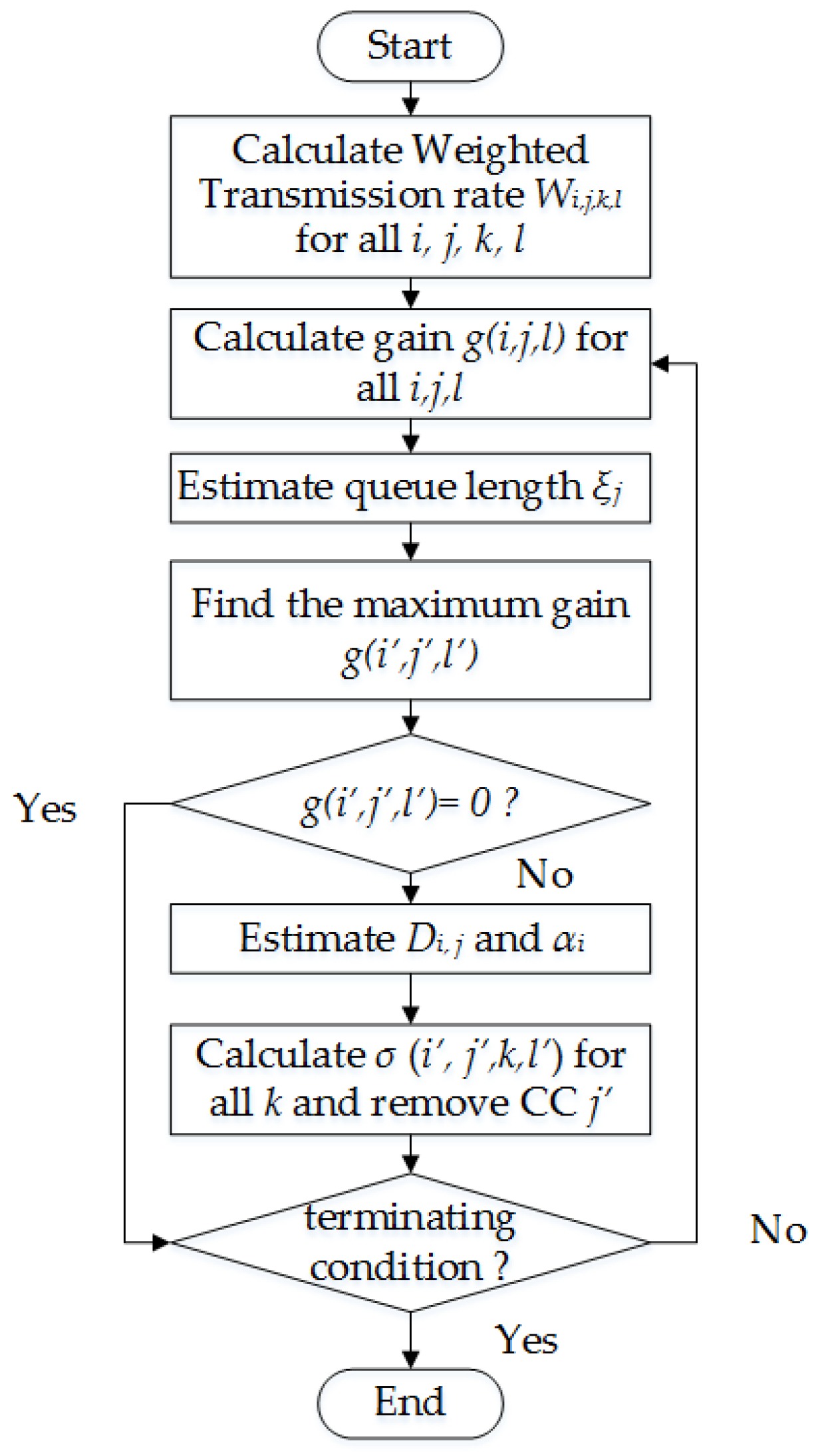
After calculating all possible gain and the corresponding queue length of the CC, if the maximum gain of a user is not greater than zero, the user i will be removed from the scheduler queue. Total number of iterations will be q × y, where y is the maximum number of CCs can be assigned to a user. The CC with the largest gain will be assigned to the user and will be removed (Line 19) from the available list of corresponding users. Therefore, the algorithm only re-calculates the gains of assigned CCs in the last iteration as the gains will be same except the first one. Thus, total computational complexity will be О(qrst + qst (y − 1)) = О(qst (r + y − 1)). Figure 2 shows the simplified steps of the proposed algorithm.
4. Results and Discussion
4.1. Simulation Settings
The MATLAB-based Vienna LTE-A system level simulator is used to implement the proposed method [32,33]. A number of simulations have been performed to evaluate the performance and compare with other well-known algorithms. Urban area with the random user deployment in the cell is considered where users are equally distributed and scattered all over the coverage area. The number of user varies from 10 to 50 in each cell with combination of active and inactive user. In this simulation, active users are transmitting and receiving data whereas the inactive users are connected to eNB but not requesting any data. The average speed of the user is 5 kmph. Four downlink CCs of 10 MHz bandwidth are used. Two CCs each are at 900 MHz and 2100 MHz frequency band. The transmission mode is single antenna and eNodeB power transmission is 46 dBm. The duration of the simulation process is set to 1000 TTI. The performance is assessed by three different types of data, namely Video, HTTP, and VoIP. According to [29], each type of these data has its own delay threshold and priority level. Video has the lowest priority among the above types of data and its delay threshold is also low. Therefore, Video type data packet would be discarded first in a congested queue. HTTP has higher priority and highest delay threshold whereas VoIP has the highest priority but it has lower delay threshold. These characteristics can affect the performance of these data types.
The performance of the proposed method is compared with largest gain PF (LG-PF) [27], least load PF (LL-PF) [28], and RR scheme [9]. In [27], joint CC assignment and PF packet scheduling are implemented. Largest gain is considered to select the CC without considering the queue length of all CCs. After assigning CC, the scheme in [27] assigns RB to the user. The scheme in [28] selects CC with lowest load and does not consider any delay or packet loss. Whereas in [9], CCs are randomly assigned to the user without considering any other parameter. However, it is less complex than the schemes are reported in [27,28]. Table 5 shows a list of simulation parameters with corresponding values.
4.2. Simulation Results
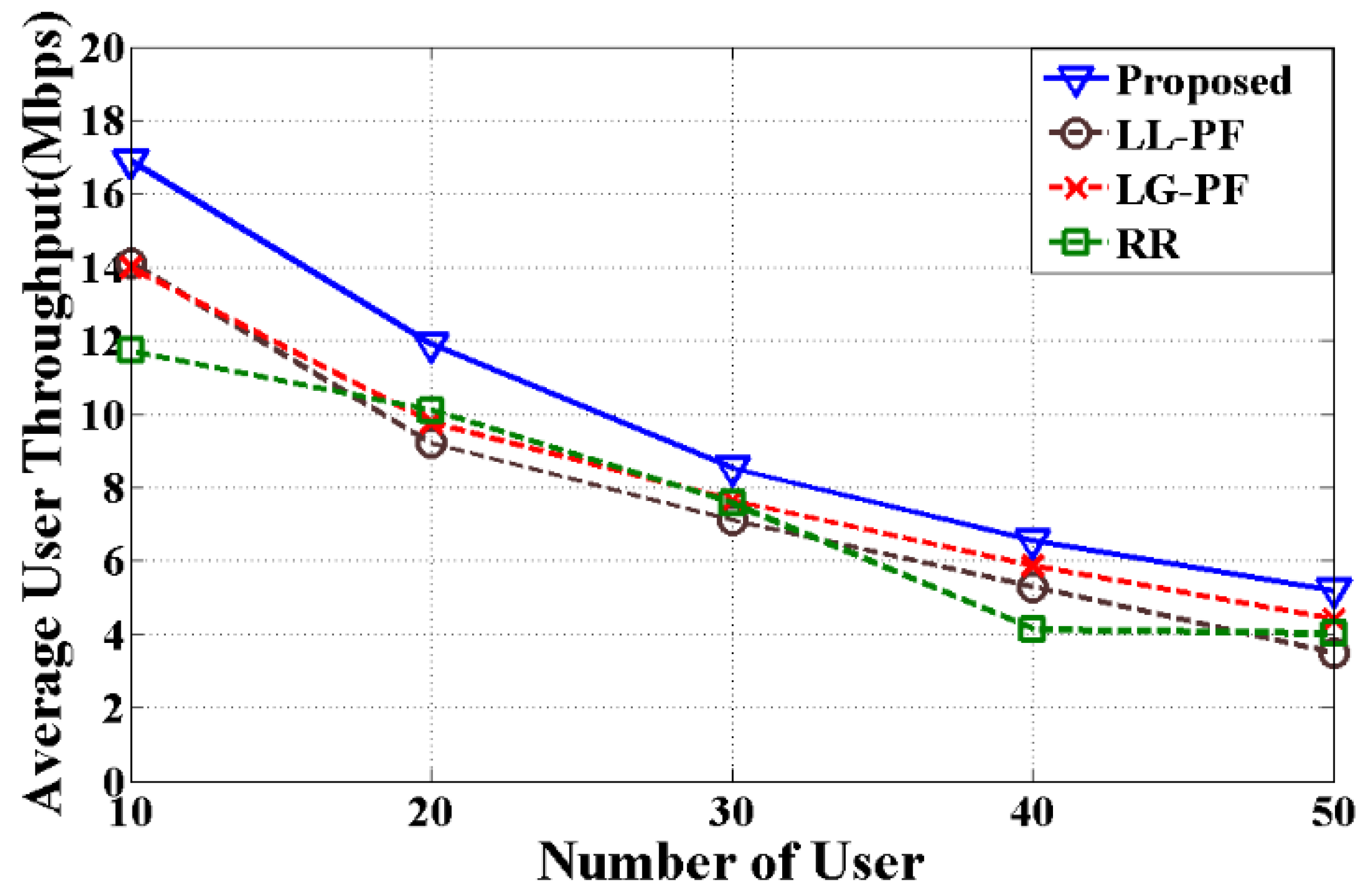
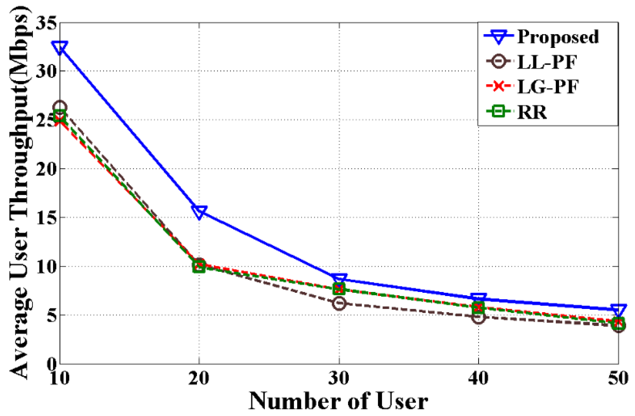
The average throughput of the user is calculated for different methods and data types with a various number of users. The ratio of total number of bits of active user and the total transmission time is considered as average user throughput. The inactive users are not considered in this case. Figure 3, Figure 4 and Figure 5 show the comparison of proposed, LL-PF, LG-PF, and RR methods for different types of data. The proposed method performs 16.73%, 26.82%, 27.95% better than LG-PF; 28.30%, 35.62%, 39.40% better than LL-PF; and 32.51%, 31.29%, 29.71% better than RR method for video, HTTP, and VoIP, respectively. As predicted, when the number of users increases, the average throughput decreases for all methods. The reasons are as follows: (a) the proposed method assigns CCs to the user by considering channel quality along with the queue length of the CCs which assures higher transmission rate and effective load balancing (however, other methods assign CCs to the user by considering only channel quality of the CCs or arbitrary selection scheme); (b) The proposed method considers the error probability for the user data and maximum delay budget of specific data type, whereas other methods do not consider these parameters, as a result, these methods incurs significant amount of data loss. From the average user throughput of all three data types in Figure 3, Figure 4 and Figure 5, it is noticed that the difference between the proposed method and other methods are wider when the number of users is less and the difference becomes narrow for the higher number of users. Efficient resource allocation is the major reason behind this issue. When the number of users is relatively less, such as 10, there are more available resources for users and the proposed method allocates RB more efficiently than other methods. However, when the number of users increases in the cell such as 50, the available resources for users are relatively less and users are getting less number of RB after scheduling.
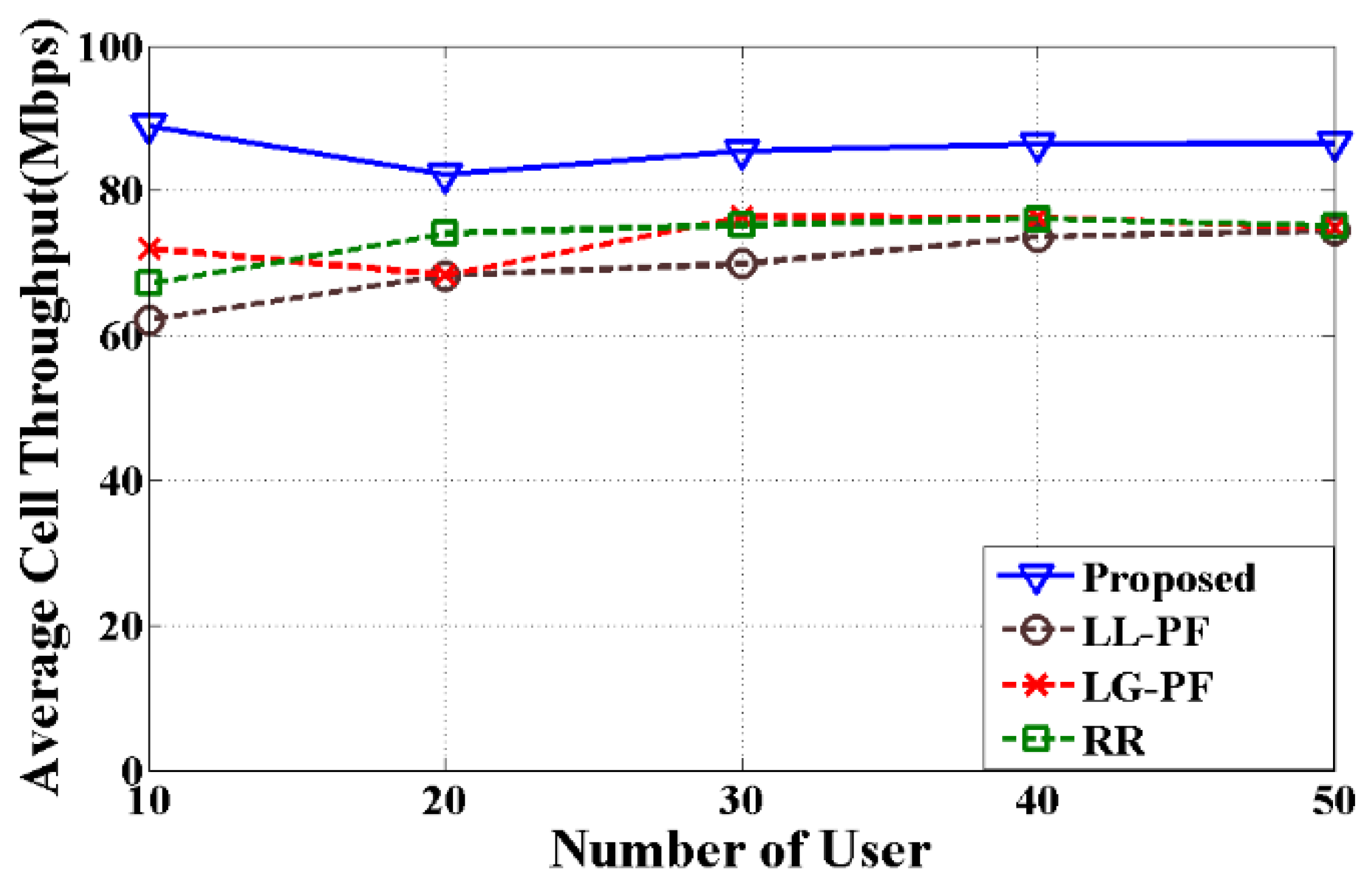
The average cell throughput is measured which is the average aggregated throughput of all active and inactive users in the cell. Therefore, the aggregated average user throughput and the cell throughput are not same as the simulation does not consider the inactive user to calculate the average user throughput. The average cell throughputs of different methods for different number of users with three data types are shown in Figure 6, Figure 7 and Figure 8. All the figures show that the proposed method outperforms other two methods. Although, the proposed model shows marginal improvements for video type data in Figure 6, it still performs 13.43%, 19.86%, and 6.38% better than LG-PF, LL-PF, and RR, respectively. Table 6 shows the average improvement of the proposed method for different number of users compared to LG-PF, LL-PF, and RR with three types of data.
The average cell throughput is affected by the following aspects: (a) when there is a lower number of users in the cell, more users will have a higher number of RBs with higher channel quality which leads to an increase in the cell throughput (b) for a higher number of users, fewer users will have RBs with higher channel quality which causes lower cell throughput. For the above reasons, average cell throughputs are highest for 10 users and lowest for 50 users in Figure 6, Figure 7 and Figure 8. When the number of users increases, average cell throughput decreases as more users share the total cell capacity. The proposed method shows 13.43%, 14.7%, 16.87% better than LG-PF, 19.86%, 10.48%, 31.81% better than LL-PF; and 6.38%, 12.64%, 17.14% better than RR method for video, HTTP, and VoIP, respectively. After analyzing the above results, it is clear that the proposed method ensures the QoS for all three types of data. Unlike the other methods, it prioritizes not only the previous rate or channel condition, but also considers HOL delay, queue condition of the CCs, and probability of packet loss. Thus, the average cell throughputs for all types of data are similar in which it proves that the proposed method can provide better QoS to all users in the cell area under all scenarios.
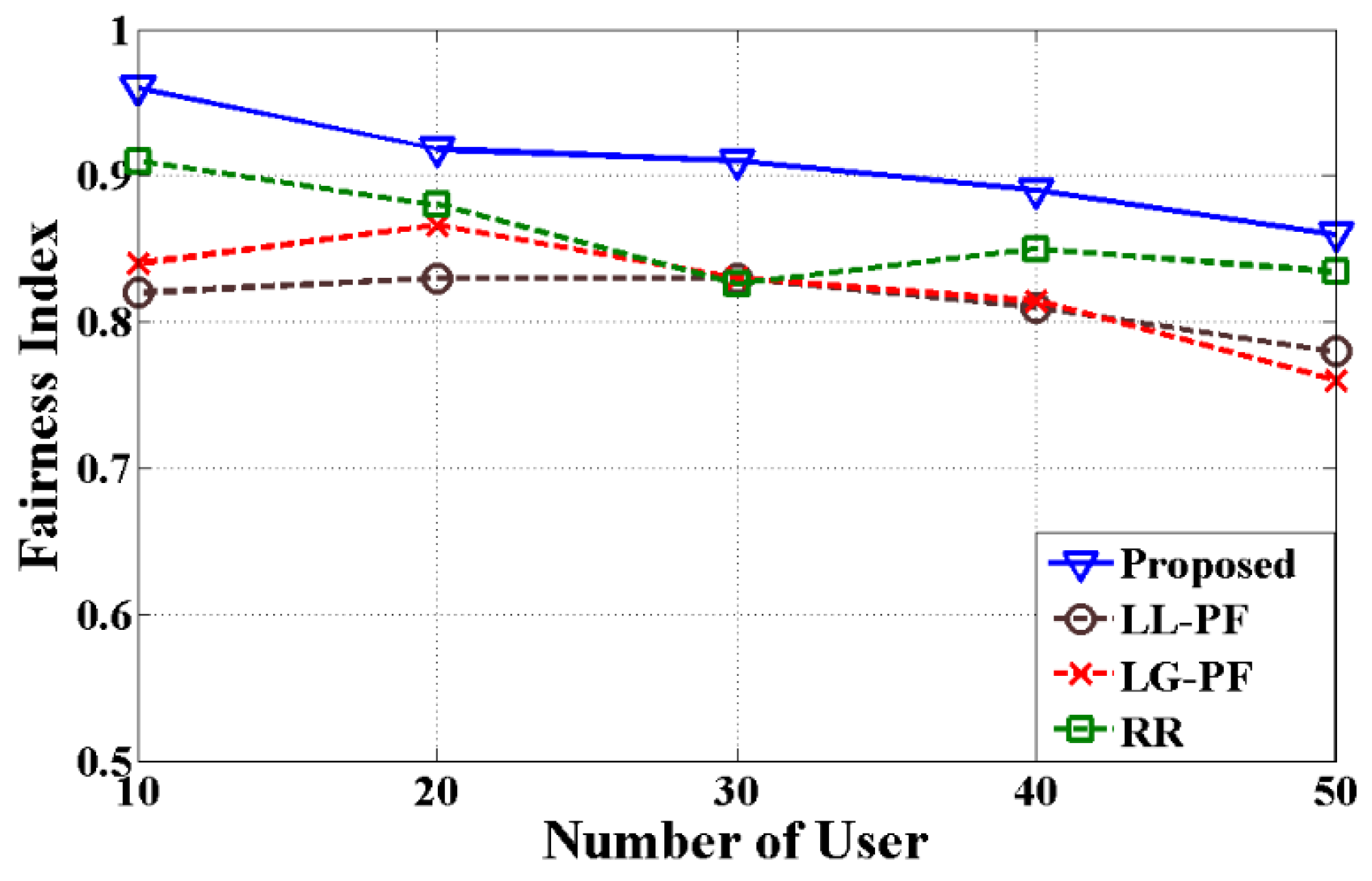
Jain’s fairness index is used to calculate and compare the fairness of the user [35]. Figure 9 presents the fairness index of different methods with various numbers of users. It is clear from this figure that the proposed method is better for fewer users in the cell and the performance is very close to each other when the number of the users increases. By considering the HOL delay and probability of packet loss, the proposed method distributes RBs efficiently to all users depending on their situation. Cell-edge users and users with bad channel quality have required RBs, which increases the fairness index. However, LG-PF, LL-PF, and RR methods assign RBs to the users without considering delay and probability of packet loss which leads to lower index. The fairness index decreases for higher number of users due to the limitation of the resources in the cell. Despite all constraints, on average, the proposed method is 10.48%, 11.49%, and 5.56% better than LG-PF, LL-PF, and RR, respectively.
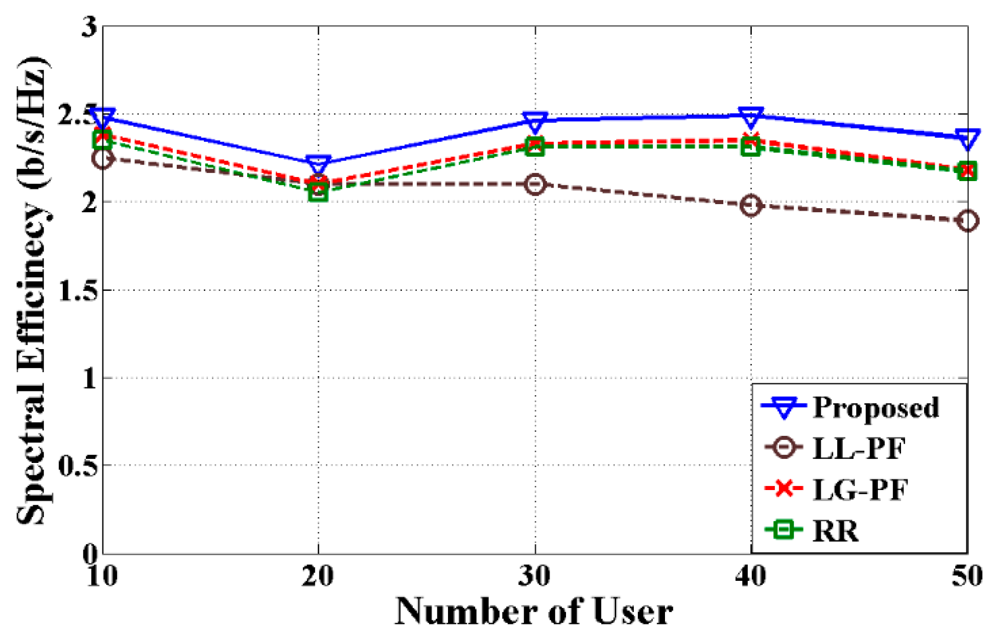
In order to estimate the spectral efficiency, mixed type of data consists of video, HTTP, and VoIP are considered. From the obtained results in Figure 10, it is clearly shown that the proposed method uses the spectrum more efficiently than the other two methods. By considering the delay threshold and probability of packet loss, the proposed method prevents the waste of the resources and increases the efficiency. On the other hand, RR is a channel unaware method which blindly allocates RBs to the user without considering the channel condition which causes the lowest spectral efficiency. However, in considering the previous data rate, the LG-PF method is marginally better than RR. Overall, the proposed method improves 5.84%, 16.65%, and 7.28% compared to LG-PF, LL-PF, and RR, respectively.
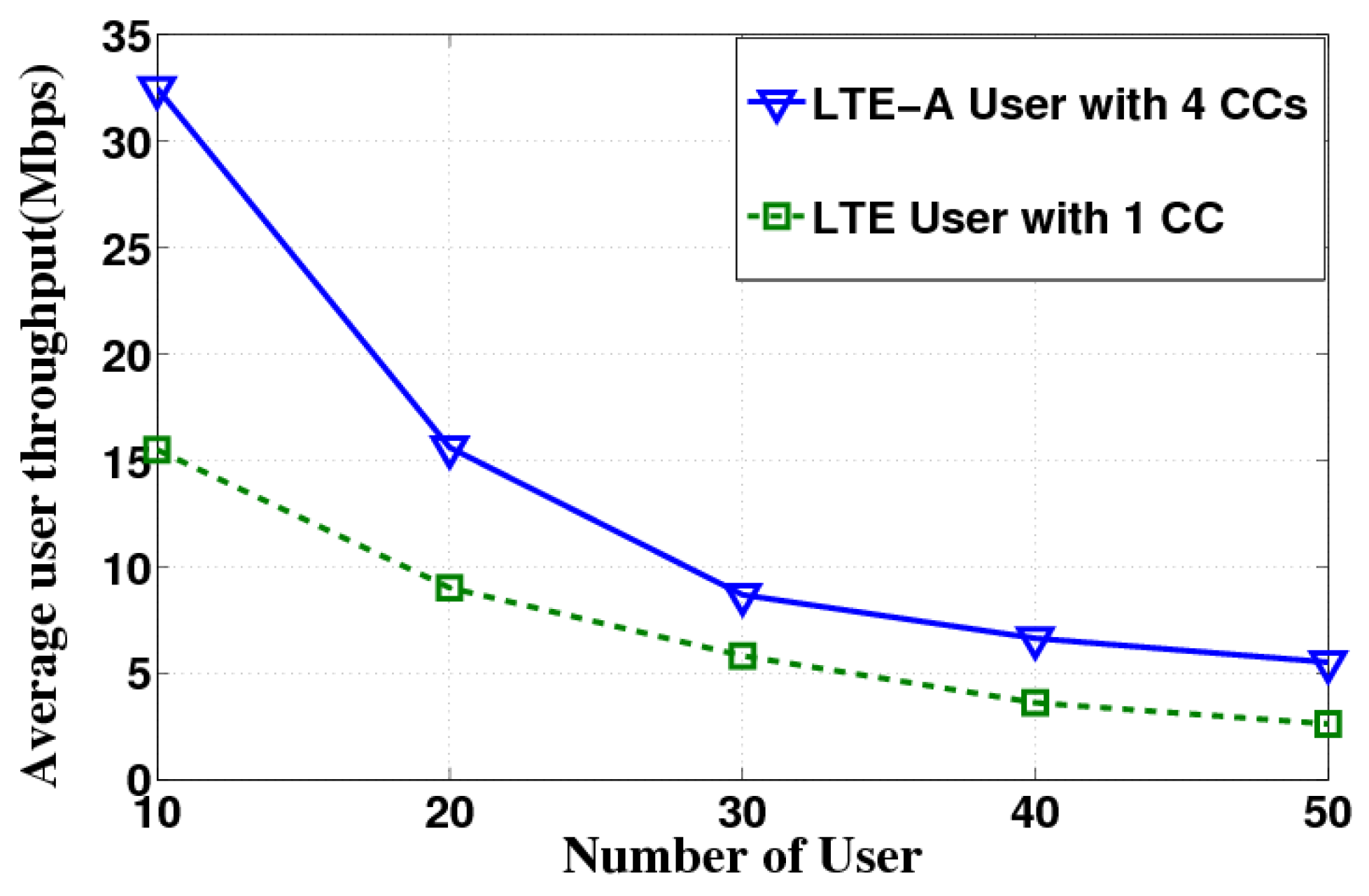
Figure 11 shows the average user throughput comparison of LTE and LTE-A users with different bandwidth. This comparison reveals the effect of the implementation of CA to all types of user in the cell. LTE users have been allocated single CC with 20 MHz of bandwidth and the LTE-A users have been allocated 4 CCs with a maximum 40 MHz of bandwidth. Simulation results show that LTE-A users achieve higher throughput than the LTE users. However, LTE users obtain a significant amount of throughput as well despite having only one CC. This proves that the proposed method can allocate resources to all users fairly and the effect of CA is marginal to LTE users.
5. Limitations and Future Work
The main objective of the proposed method is to improve the QoS with carrier aggregation by allocating RBs efficiently to the user. In the case of a higher number of users in the cell, average throughput decreases due to the higher congestion and lack of available resources. Fairness index is also not showing a significant improvement, although the proposed method performs better than other methods.
As a future work, the plan is to extend the radio resource management approach by introducing enhanced multiple input multiple output (MIMO) technique. This will help to increase the capacity of the cell. QoS of the cell-edge user and user with bad channel condition will improve with additional antenna and more transmission capability of the enhanced MIMO technique. Moreover, this technique can serve more users to reduce the aforementioned limitations. Coordinated multipoint transmission and reception (CoMP) is another system which can boost the user throughput. By adding these systems to the resource management approach, users will have further improved system efficiency and better coverage in the future LTE-A network.
6. Conclusions
This paper has inspected the downlink radio resource management problem with CA for the LTE-A network. The problem involves with CC selection and RBs allocation of the selected CCs under specific constraints as specified in LTE-A standard. The resource management problem has been formulated and an improved method based on several parameters, such as the head of line delay and delay threshold, has been developed. This proposed method can increase the system throughput and maximize the QoS of the user while ensuring better spectral efficiency and low computational complexity. The queue length of each CC is taken into account to balance the load among all CCs. A set of system-level simulations have been performed to support the proposed method. The obtained results demonstrated that the proposed method significantly improves the user throughput up to 39.40% compared to the well-known method of previous studies. Thus, it can be concluded that the proposed method is a better implementation alternative as it is capable of improving the overall performance of LTE-A system with CA.
Acknowledgments
This research work is supported by the University of Malaya Center of Research Grant Management (PPGP) scheme (PV001-2014).
Author Contributions
Hasibur Rashid Chayon and Harikrishnan Ramiah conceived and designed the experiments; Hasibur Rashid Chayon performed the experiments; Hasibur Rashid Chayon, Ahmed Wasif Reza, and Kaharudin Dimyati analyzed the data; Harikrishnan Ramiah, Kaharudin Dimyati, and Ahmed Wasif Reza contributed reagents/materials/analysis tools; Hasibur Rashid Chayon wrote the paper.
Conflicts of Interest
The authors declare no conflict of interest. The funding sponsors had no role in the design of the study; in the collection, analyses, or interpretation of data; in the writing of the manuscript, or in the decision to publish the results.
References
- Requirements for Further Advancements for Evolved Universal Terrestrial Radio Access (E-UTRA) (LTE-Advanced); Technical Report 36.913 V11.0.0; 3rd Generation Partnership Project (3GPP): Valbonne, France, September 2012.
- Evolved Universal Terrestrial Radio Access (E-UTRA) and Evolved Universal Terrestrial Radio Access Network (E-UTRAN); Overall Description; Stage 2, Technical Specification 36.300; 3rd Generation Partnership Project (3GPP): Valbonne, France, July 2012.
- LTE Carrier Aggregation Technology Development and Deployment Worldwide. White Paper. 4G Americas. October 2014. Available online: http://www.4gamericas.org/files/8414/1471/2230/4G_Americas_Carrier_Aggregation_FINALv1_0_3.pdf (accessed on 11 July 2016).
- Yuan, G.; Zhang, X.; Wang, W.; Yang, Y. Carrier aggregation for LTE-advanced mobile communication systems. IEEE Commun. Mag. 2010, 48, 88–93. [Google Scholar] [CrossRef]
- Rostami, S.; Arshad, K.; Rapajic, P. A joint resource allocation and link adaptation algorithm with carrier aggregation for 5G LTE-Advanced network. In Proceedings of the IEEE 22nd International Conference on Telecommunications (ICT), Sydney, Australia, 27–29 April 2015; pp. 102–106. [Google Scholar]
- Lee, H.; Vahid, S.; Moessner, K. A survey of radio resource management for spectrum aggregation in LTE-advanced. IEEE Commun. Surv. Tutor. 2014, 16, 745–760. [Google Scholar] [CrossRef]
- Wang, Y.; Pedersen, K.; Mogensen, P.E.; Sørensen, T.B. Resource allocation considerations for multi-carrier LTE-Advanced systems operating in backward compatible mode. In Proceedings of the IEEE 20th International Symposium on Personal, Indoor and Mobile Radio Communications, Toyko, Japan, 13–16 September 2009; pp. 370–374. [Google Scholar]
- Zhang, L.; Wang, Y.; Huang, L.; Wang, H.; Wang, W. QoS performance analysis on carrier aggregation based LTE-A systems. In Proceedings of the IET International Communication Conference on Wireless Mobile and Computing (CCWMC 2009), Shanghai, China, 7–9 December 2009; pp. 253–256. [Google Scholar]
- Zhang, L.; Liu, F.; Huang, L.; Wang, W. Traffic load balance methods in the LTE-Advanced system with carrier aggregation. In Proceedings of the IEEE International Conference on Communications, Circuits and Systems (ICCCAS), Chengdu, China, 28–30 July 2010; pp. 63–67. [Google Scholar]
- Wang, Y.; Pedersen, K.; Sørensen, T.B.; Mogensen, P.E. Utility maximization in LTE-advanced systems with carrier aggregation. In Proceedings of the IEEE 73rd Vehicular Technology Conference (VTC Spring), Budapest, Hungary, 15–18 May 2011; pp. 1–5. [Google Scholar]
- Ragaleux, A.; Baey, S.; Gueguen, C. Adaptive and Generic Scheduling Scheme for LTE/LTE-A Mobile Networks. Wirel. Netw. 2016, 22, 2753–2771. [Google Scholar] [CrossRef]
- Ferdosian, N.; Othman, M.; Ali, B.M.; Lun, K.Y. Multi-Targeted Downlink Scheduling for Overload-States in LTE Networks: Proportional Fractional Knapsack Algorithm with Gaussian Weights. IEEE Access 2017, 5, 3016–3027. [Google Scholar] [CrossRef]
- Ferdosian, N.; Othman, M.; Ali, B.M.; Lun, K.Y. Greedy–knapsack algorithm for optimal downlink resource allocation in LTE networks. Wirel. Netw. 2016, 22, 1427–1440. [Google Scholar] [CrossRef]
- Xenakis, D.; Passas, N.; Merakos, L.; Verikoukis, C. Mobility management for femtocells in LTE-advanced: Key aspects and survey of handover decision algorithms. IEEE Commun. Surv. Tutor. 2014, 16, 64–91. [Google Scholar] [CrossRef]
- Zorba, N.; Verikoukis, C. Joint uplink-downlink carrier aggregation scheme in LTE-A. In Proceedings of the IEEE 21st International Workshop on Computer Aided Modelling and Design of Communication Links and Networks (CAMAD), Toronto, ON, Canada, 23–25 October 2016; pp. 117–121. [Google Scholar]
- Zorba, N.; Verikoukis, C. Energy optimization for bidirectional multimedia communication in unsynchronized TDD systems. IEEE Syst. J. 2016, 10, 797–804. [Google Scholar] [CrossRef]
- Ramazanali, H.; Mesodiakaki, A.; Vinel, A.; Verikoukis, C. Survey of user association in 5G HetNets. In Proceedings of the 8th IEEE Latin-American Conference on Communications (LATINCOM), Medellin, Colombia, 16–18 November 2016; pp. 1–6. [Google Scholar]
- Andrews, M.; Kumaran, K.; Ramanan, K.; Stolyar, A.; Whiting, P.; Vijayakumar, R. Providing quality of service over a shared wireless link. IEEE Commun. Mag. 2001, 39, 150–154. [Google Scholar] [CrossRef]
- Stolyar, A.L.; Ramanan, K. Largest weighted delay first scheduling: Large deviations and optimality. Ann. Appl. Probab. 2001, 11, 1–48. [Google Scholar] [CrossRef]
- Ameigeiras, P.; Wigard, J.; Mogensen, P. Performance of the M-LWDF scheduling algorithm for streaming services in HSDPA. In Proceedings of the IEEE 60th Vehicular Technology Conference (VTC2004-Fall), Los Angeles, CA, USA, 26–29 September 2004; Volume 2, pp. 999–1003. [Google Scholar]
- Evolved Universal Terrestrial Radio Access (E-UTRA); Packet Data Convergence Protocol (PDCP); TS 25.323 V3.3.0; 3rd Generation Partnership Project (3GPP): Valbonne, France, April 2007.
- Ku, G.; Walsh, J.M. Resource allocation and link adaptation in LTE and LTE advanced: A tutorial. IEEE Commun. Surv. Tutor. 2014, 17, 1605–1633. [Google Scholar] [CrossRef]
- Lee, K.K.; Chanson, S.T. Packet loss probability for real-time wireless communications. IEEE Trans. Veh. Technol. 2002, 51, 1569–1575. [Google Scholar] [CrossRef]
- Meucci, F.; Cabral, O.; Velez, F.J.; Mihovska, A.; Prasad, N.R. Spectrum aggregation with multi-band user allocation over two frequency bands. In Proceedings of the IEEE Mobile WiMAX Symposium, Napa, CA, USA, 9–10 July 2009; pp. 81–86. [Google Scholar]
- Songsong, S.; Chunyan, F.; Caili, G. A resource scheduling algorithm based on user grouping for LTE-advanced system with carrier aggregation. In Proceedings of the International Symposium on Computer Network and Multimedia Technology (CNMT 2009), Wuhan, China, 18–20 December 2009; pp. 1–4. [Google Scholar]
- Liu, L.; Li, M.; Zhou, J.; She, X.; Chen, L.; Sagae, Y.; Iwamura, M. Component carrier management for carrier aggregation in LTE-advanced system. In Proceedings of the IEEE 73rd Vehicular Technology Conference (VTC Spring), Budapest, Hungary, 15–18 May 2011; pp. 1–6. [Google Scholar]
- Liao, H.-S.; Chen, P.-Y.; Chen, W.-T. An efficient downlink radio resource allocation with carrier aggregation in LTE-advanced networks. IEEE Trans. Mob. Comput. 2014, 13, 2229–2239. [Google Scholar] [CrossRef]
- Wang, Y.; Pedersen, K.; Sørensen, T.B.; Mogensen, P.E. Carrier load balancing and packet scheduling for multi-carrier systems. IEEE Trans. Wirel. Commun. 2010, 9, 1780–1789. [Google Scholar] [CrossRef]
- General Packet Radio Service (GPRS) enhancements for Evolved Universal Terrestrial Radio Access Network (E-UTRAN) Access; TS 23.401 V8.1.0; 3rd Generation Partnership Project (3GPP): Valbonne, France, April 2008.
- Nasralla, M.M.; Hewage, C.T.; Martini, M.G. Subjective and objective evaluation and packet loss modeling for 3d video transmission over LTE networks. In Proceedings of the IEEE International Conference on Telecommunications and Multimedia (TEMU), Heraklion, Crete, Greece, 28–30 July 2014; pp. 254–259. [Google Scholar]
- Anchora, L.; Canzian, L.; Badia, L.; Zorzi, M. A characterization of resource allocation in LTE systems aimed at game theoretical approaches. In Proceedings of the 15th IEEE International Workshop on Computer Aided Modeling, Analysis and Design of Communication Links and Networks (CAMAD), Miami, FL, USA, 3–4 December 2010; pp. 47–51. [Google Scholar]
- Rupp, M.; Schwarz, S.; Taranetz, M. The Vienna LTE-Advanced Simulators; Springer: Berlin, Germany, 2016. [Google Scholar]
- Institute of Telecommunications, Vienna University of Technology. Vienna LTE-A Simulators. Available online: https://www.nt.tuwien.ac.at/research/mobile-communications/vienna-lte-a-simulators/ (accessed on 22 April 2016).
- Evolved Universal Terrestrial Radio Access (E-UTRA); Physical Layer Procedures; Technical Specification 36.213 V11.0.0; 3rd Generation Partnership Project (3GPP): Valbonne, France, September 2012.
- Jain, R.; Chiu, D.-M.; Hawe, W.R. A Quantitative Measure of Fairness and Discrimination for Resource Allocation in Shared Computer System; Eastern Research Laboratory, Digital Equipment Corporation: Hudson, MA, USA, 1984; Volume 38. [Google Scholar]
Figure 1.
RRM framework with carrier aggregation.

Figure 2.
Simplified steps of the proposed algorithm.

Figure 3.
Average user throughput for video.

Figure 4.
Average user throughput for VoIP.

Figure 5.
Average user throughput for HTTP.
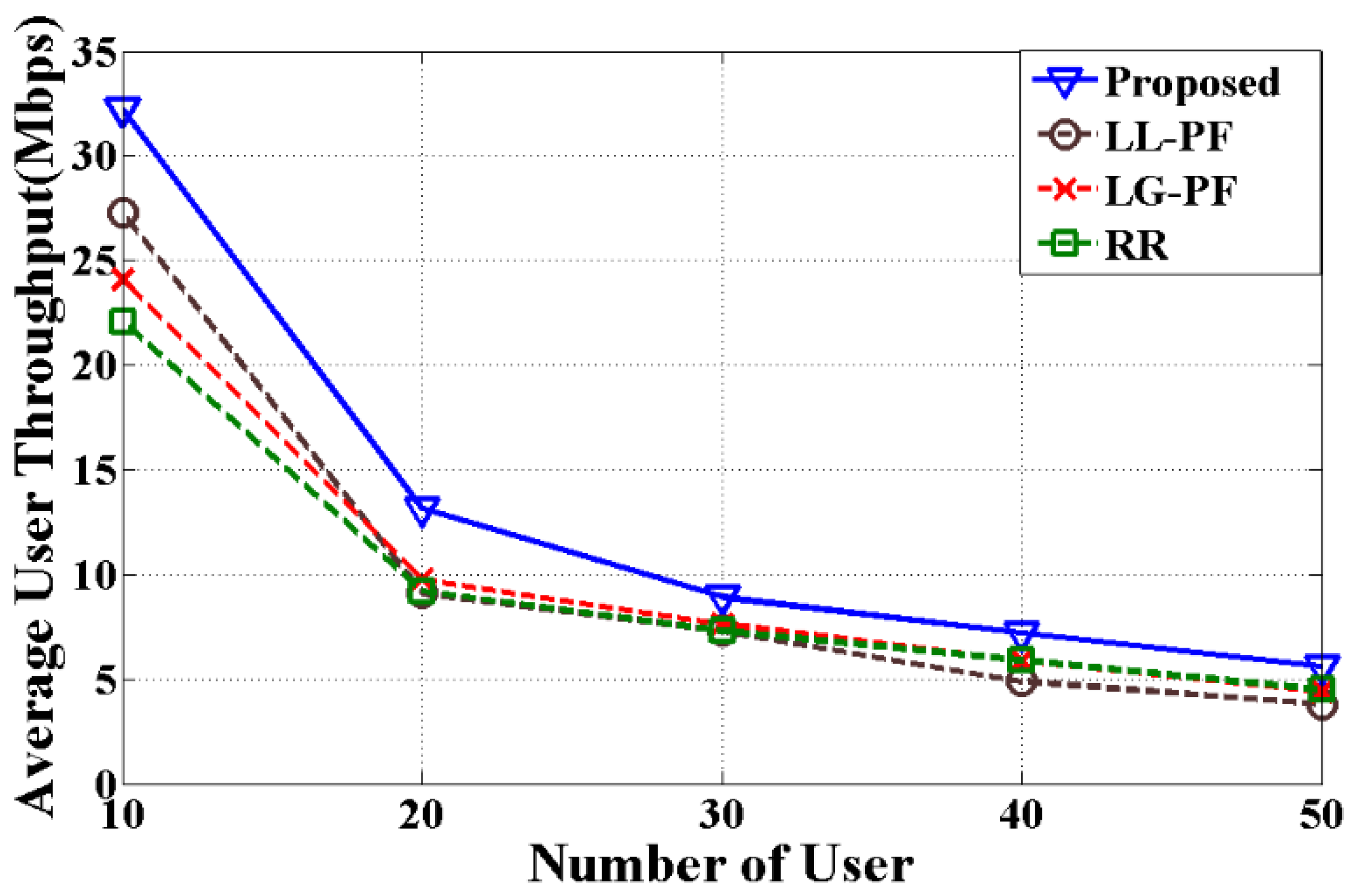
Figure 6.
Average cell throughput for video.
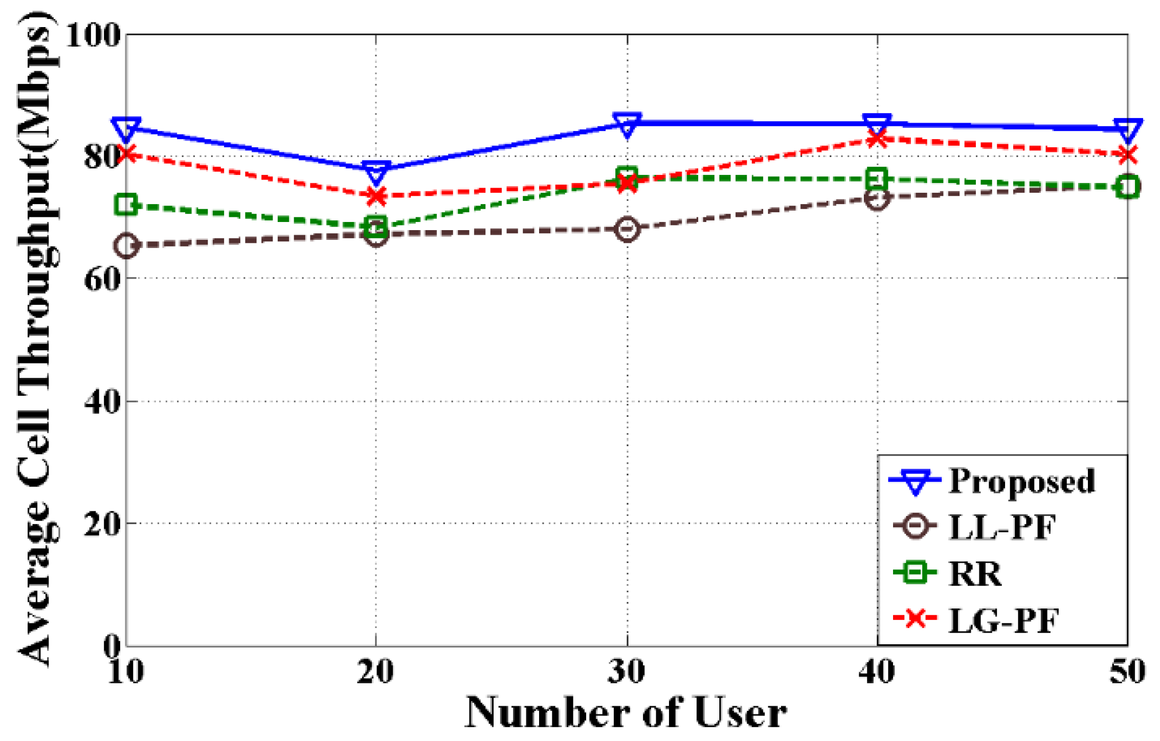
Figure 7.
Average cell throughput for VoIP.

Figure 8.
Average cell throughput for HTTP.
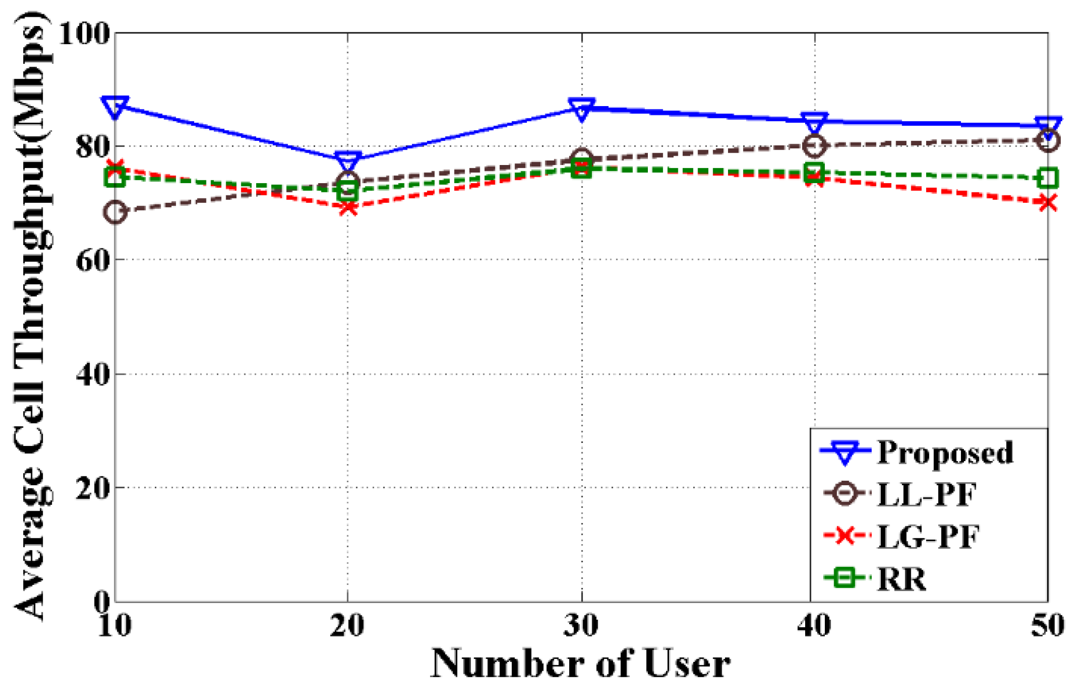
Figure 9.
Fairness index for different number of users.

Figure 10.
Spectral efficiency for different number of users.

Figure 11.
Throughput comparison of LTE and LTE-A user.

Table 1.
Summary of related work regarding CC assignment and RB allocation.
| CC Selection Method | Packet Scheduler | Characteristics | Reference |
|---|---|---|---|
| Random selection with load balancing | Cross-CC PF |
| [7] |
| Circular selection | RR |
| [9] |
| Inter-band carrier switch | PF |
| [24] |
| Lowest path loss | User grouping PF (UG-PF) |
| [25] |
| Absolute and Relative policy | PF |
| [26] |
| Largest gain | PF |
| [27] |
| Least load | PF |
| [28] |
Table 2.
Symbols used in the paper.
| Symbol | Definition |
|---|---|
| i | User, i ϵ Q = {1, …., Q} |
| j | CC, j ϵ R = {1, …., R} |
| k | RB, k ϵ S = {1, …., S} |
| l | MSC index, l ϵ T = {1, …., T} |
| m | Maximum number of CC can be assigned to a user |
| t | Time (TTI index) |
| ψi,j,k,l | A variable to denote whether or not CC j, RB k and MSC l is assigned to user i |
| Wi,j,k,l | Weighted transmission rate of user i, CC j, RB k, and MSC l |
| Di,j | Head of line delay of user i, CC j |
| ξj | Queue length of CC j |
| δi | Probability of packet loss of user i |
| Ω (j, k) | Transmission rate of user currently being allocated with CC j and RB k |
| g (i, j, l) | The gain after assigning CC j and MSC l to user i |
| σ (i, j, k, l) | Weighted transmission rate metric with packet loss and delay |
Table 3.
Delay threshold value for different applications [29].
Table 3.
Delay threshold value for different applications [29].
| Application | Delay Threshold in ms | Priority Level |
|---|---|---|
| Real time gaming | 50 | 3 |
| Live video streaming | 100 | 7 |
| Conversational voice | 100 | 2 |
| HTTP, FTP | 300 | 6 |
Table 4.
Proposed greedy-based method.
| Algorithm 1 Proposed method |
| 1: Ω (j, k) = 0 for all CC j and RB k |
| 2: Calculate Wi,j,k,l for all i ϵ Q, j ϵ R, k ϵ S, l ϵ T |
| 3: repeat |
| 4: Calculate gain g (i, j, l) for all i, j and l |
| 5: Calculate Queue length ξj for each CC j |
| 6: (i′, j′, l′) = argmax i ϵ Q, j ϵ R,lϵ T g (i, j, l)/ξj |
| 7: if g (i′, j′, l′) = 0 |
| 8: go to line 21; otherwise |
| 9: Assign CC j′ to user i′ with MSC l′ |
| 10: Calculate Head of Line Delay Di′, j′ of user i′ for CC j′ |
| 11: Estimate the variable αi′ of user i′ |
| 12: for each k ϵ S do |
| 13: σ (i′, j′, k, l′) = Wi′, j′, k, l′ * αi’ * Di′, j′ |
| 14: if σ (i′, j′, k, l′) > Ω (j′, k) then |
| 15: Assign RB k of CC j′ to user i′ |
| 16: Ω (j′, k) = σ (i′, j′, k, l′) |
| 17: end if |
| 18: end for |
| 19: Remove CC j′ associated with user i′ |
| 20: end if |
| 21: until reach any terminating condition |
Table 5.
Simulation parameters.
| Parameters | Values |
|---|---|
| Operating frequency band | 900 MHz and 2100 MHz |
| Total bandwidth | 40 MHz (4 × 10 MHz) |
| Scenario | Urban (Random user deployment) |
| Number of users | 10, 20, 30, 40, 50 |
| User speed | 5 kmph |
| Scheduling algorithm | Proposed algorithm, LL-PF, LG-PF, RR |
| MSC index | 29 available MSCs as in 3GPP [34] |
| eNodeB power transmission | 46 dBm |
| Thermal noise density of the user | −174 dBm |
| Simulation time | 1000 TTI |
| Traffic model | Video, VoIP, HTTP |
| Operating frequency band | 900 MHz and 2100 MHz |
| Total bandwidth | 40 MHz (4 × 10 MHz) |
| Scenario | Urban (Random user deployment) |
Table 6.
Average improvement of proposed method.
| Traffic Model | Algorithm | Average User Throughput (%) | Average Cell Throughput (%) |
|---|---|---|---|
| Video | LG-PF | 16.73 | 13.43 |
| LL-PF | 28.30 | 19.86 | |
| RR | 32.51 | 6.38 | |
| HTTP | LG-PF | 26.82 | 14.70 |
| LL-PF | 35.62 | 10.48 | |
| RR | 31.29 | 12.64 | |
| VoIP | LG-PF | 27.95 | 16.87 |
| LL-PF | 39.40 | 31.81 | |
| RR | 29.71 | 17.14 |
© 2017 by the authors. Licensee MDPI, Basel, Switzerland. This article is an open access article distributed under the terms and conditions of the Creative Commons Attribution (CC BY) license (http://creativecommons.org/licenses/by/4.0/).
Share and Cite
MDPI and ACS Style
Chayon, H.R.; Dimyati, K.; Ramiah, H.; Reza, A.W. An Improved Radio Resource Management with Carrier Aggregation in LTE Advanced. Appl. Sci. 2017, 7, 394. https://doi.org/10.3390/app7040394
AMA Style
Chayon HR, Dimyati K, Ramiah H, Reza AW. An Improved Radio Resource Management with Carrier Aggregation in LTE Advanced. Applied Sciences. 2017; 7(4):394. https://doi.org/10.3390/app7040394
Chicago/Turabian StyleChayon, Hasibur Rashid, Kaharudin Dimyati, Harikrishnan Ramiah, and Ahmed Wasif Reza. 2017. "An Improved Radio Resource Management with Carrier Aggregation in LTE Advanced" Applied Sciences 7, no. 4: 394. https://doi.org/10.3390/app7040394
Note that from the first issue of 2016, this journal uses article numbers instead of page numbers. See further details here.